EP3650971B1 - Unabhängiges wagensystem und verfahren zum betrieb davon - Google Patents
Unabhängiges wagensystem und verfahren zum betrieb davon Download PDFInfo
- Publication number
- EP3650971B1 EP3650971B1 EP19208005.9A EP19208005A EP3650971B1 EP 3650971 B1 EP3650971 B1 EP 3650971B1 EP 19208005 A EP19208005 A EP 19208005A EP 3650971 B1 EP3650971 B1 EP 3650971B1
- Authority
- EP
- European Patent Office
- Prior art keywords
- track
- mover
- controller
- drive
- movers
- Prior art date
- Legal status (The legal status is an assumption and is not a legal conclusion. Google has not performed a legal analysis and makes no representation as to the accuracy of the status listed.)
- Active
Links
Images


Classifications
-
- B—PERFORMING OPERATIONS; TRANSPORTING
- B61—RAILWAYS
- B61L—GUIDING RAILWAY TRAFFIC; ENSURING THE SAFETY OF RAILWAY TRAFFIC
- B61L23/00—Control, warning or like safety means along the route or between vehicles or trains
- B61L23/08—Control, warning or like safety means along the route or between vehicles or trains for controlling traffic in one direction only
- B61L23/14—Control, warning or like safety means along the route or between vehicles or trains for controlling traffic in one direction only automatically operated
-
- G—PHYSICS
- G05—CONTROLLING; REGULATING
- G05B—CONTROL OR REGULATING SYSTEMS IN GENERAL; FUNCTIONAL ELEMENTS OF SUCH SYSTEMS; MONITORING OR TESTING ARRANGEMENTS FOR SUCH SYSTEMS OR ELEMENTS
- G05B19/00—Program-control systems
- G05B19/02—Program-control systems electric
- G05B19/418—Total factory control, i.e. centrally controlling a plurality of machines, e.g. direct or distributed numerical control [DNC], flexible manufacturing systems [FMS], integrated manufacturing systems [IMS] or computer integrated manufacturing [CIM]
- G05B19/4189—Total factory control, i.e. centrally controlling a plurality of machines, e.g. direct or distributed numerical control [DNC], flexible manufacturing systems [FMS], integrated manufacturing systems [IMS] or computer integrated manufacturing [CIM] characterised by the transport system
-
- B—PERFORMING OPERATIONS; TRANSPORTING
- B61—RAILWAYS
- B61C—LOCOMOTIVES; MOTOR RAILCARS
- B61C3/00—Electric locomotives or railcars
-
- B—PERFORMING OPERATIONS; TRANSPORTING
- B61—RAILWAYS
- B61L—GUIDING RAILWAY TRAFFIC; ENSURING THE SAFETY OF RAILWAY TRAFFIC
- B61L25/00—Recording or indicating positions or identities of vehicles or trains or setting of track apparatus
- B61L25/02—Indicating or recording positions or identities of vehicles or trains
- B61L25/04—Indicating or recording train identities
-
- G—PHYSICS
- G05—CONTROLLING; REGULATING
- G05D—SYSTEMS FOR CONTROLLING OR REGULATING NON-ELECTRIC VARIABLES
- G05D1/00—Control of position, course, altitude or attitude of land, water, air or space vehicles, e.g. using automatic pilots
- G05D1/0088—Control of position, course, altitude or attitude of land, water, air or space vehicles, e.g. using automatic pilots characterized by the autonomous decision making process, e.g. artificial intelligence, predefined behaviours
-
- G—PHYSICS
- G05—CONTROLLING; REGULATING
- G05D—SYSTEMS FOR CONTROLLING OR REGULATING NON-ELECTRIC VARIABLES
- G05D1/00—Control of position, course, altitude or attitude of land, water, air or space vehicles, e.g. using automatic pilots
- G05D1/02—Control of position or course in two dimensions
- G05D1/021—Control of position or course in two dimensions specially adapted to land vehicles
- G05D1/0287—Control of position or course in two dimensions specially adapted to land vehicles involving a plurality of land vehicles, e.g. fleet or convoy travelling
- G05D1/0291—Fleet control
-
- G—PHYSICS
- G05—CONTROLLING; REGULATING
- G05B—CONTROL OR REGULATING SYSTEMS IN GENERAL; FUNCTIONAL ELEMENTS OF SUCH SYSTEMS; MONITORING OR TESTING ARRANGEMENTS FOR SUCH SYSTEMS OR ELEMENTS
- G05B2219/00—Program-control systems
- G05B2219/30—Nc systems
- G05B2219/41—Servomotor, servo controller till figures
- G05B2219/41327—Linear induction motor
-
- G—PHYSICS
- G05—CONTROLLING; REGULATING
- G05B—CONTROL OR REGULATING SYSTEMS IN GENERAL; FUNCTIONAL ELEMENTS OF SUCH SYSTEMS; MONITORING OR TESTING ARRANGEMENTS FOR SUCH SYSTEMS OR ELEMENTS
- G05B2219/00—Program-control systems
- G05B2219/30—Nc systems
- G05B2219/45—Nc applications
- G05B2219/45054—Handling, conveyor
Definitions
- ICT independent cart technology
- An independent cart system (ICS) utilizing movers can be used in a wide variety of processes (e.g. packaging, manufacturing, and machining). ICSs can provide an advantage over conventional conveyor belt systems with enhanced flexibility, extremely high-speed movement, and mechanical simplicity. Successive activation of electric coils establishes a moving electromagnetic field that interacts with magnets of a mover and causes the mover to travel along a track. Sensors may be spaced at fixed positions along the track and/or on the movers to provide information about the position and speed of the movers.
- the track forms a closed path over which each mover repeatedly travels.
- other actuators e.g., part of a robotic system
- the mover may be stopped at a loading station at which a first actuator places a product on the mover.
- the mover may then be moved along a process portion of the track where various other actuators may fill, machine, position, or otherwise interact with the product on the mover.
- the mover may be programmed to stop at various locations or to move at a controlled speed past each of the other actuators.
- the mover may pass or stop at an unloading station at which the product is removed from the mover.
- the mover then completes a cycle along the closed path by returning to the loading station to receive another unit of the product.
- the ICS and the external actuator(s) collectively form an automated transport system.
- a central computer for a motion control system collects and distributes servo control state variables for all movers and track segments in the system.
- the central computer referred to by some as a "gateway computer," has connections to a system controller performing coordinated motion and to all of the track segments.
- the central computer distributes control state variables to the individual track segments for motion control of the movers. Utilizing a central computer results in high costs for small tracks and slow update rates between the central computer and the individual track segments.
- US 2016/139585 A1 relates to modular control of a linear drive with communication.
- a plurality of sequentially consecutive sections of a linear drive are each controlled case by a respective control device that is assigned to a respective section of the plurality of sequentially consecutive sections, where converters that are controlled by the respective control device each individually apply current to a subsection of the respective section, and collectively to the respective section, control devices each specify new desired values to the converters they control, the respective control device controls each respective convertor of a plurality of converters, and where the control devices communicate, via respective peer-to-peer interfaces having real-time capability, with a number of other control devices that control sections.
- WO 98/50760 A2 relates to a modular conveyor system having multiple moving elements under independent control.
- the modular conveyor system comprises n interconnected track sections, forming a continuous track, wherein each track section features a plurality of individually controlled coils stretching along the length thereof.
- Plural pallets, each having thrust producing magnets, travel independently along the track.
- the track also comprises multiple linear encoder readers spaced at fixed positions therealong, and each pallet includes a linear encoder strip having a length R greater than the spacing E between the readers.
- Track section controllers associate the encoder strips with only one reader at any time in order to resolve the position of the pallets based on the fixed position of the readers and the relative positions of the strips in relation thereto.
- the section controllers also regulate and commutate the coils of the corresponding track sections in order to independently control each pallet.
- Communication links interface adjacent section controllers and enable them to transfer the pallet position-detecting responsibility between one another when a given pallet straddles adjacent track sections.
- the section controllers also provide coil regulating signals to each other in the event a given moving element spans coils situated in adjacent track sections.
- the electromagnetic structure and distributed control architecture of the conveyor system enable it to independently control multiple practical pallets yet be constructed out of modular track sections, with little practical restriction on the length of the conveyor system or the number of pallets controlled thereby.
- WO 2017/089182 A1 relates to a method for moving a rotor onto a segment, to a linear drive, to a production machine, to a machine tool, and to a packaging machine comprising such a linear drive.
- the actual speed of the rotor is ascertained using a sensor which is paired with the segment.
- the actual speed is selected by a control unit as the first target speed for the rotor.
- the regulation of the actual speed is activated for the rotor.
- the actual speed of the rotor is then regulated according to a conventional rule, wherein the rule variable is the ascertained actual speed and/or the position of the rotor.
- the aforementioned method is used to prevent jerking or an undesired acceleration during the transition of the rotor onto a segment.
- an improved method and system for motion control of movers in ICSs includes partitioning servo control commands into motion control commands and force control commands, and separating execution of these functions.
- the method and system allow a fixed connection to the motion controller but enable distributed control over multiple track segments on a track. Motion control responsibility for all the movers in the ICS are spread over many devices and does not have to be concentrated on one device.
- the embodiments eliminate the centralized computer as a gateway between the system controller doing coordinated motion and the track segments doing the motion movement. The elimination of the central computer allows for smaller tracks to be more cost effective, but the automated transport system also supports large tracks (e.g., up to 128 movers on 64 segments). The system provides enough computing power to perform motion control, but minimize product cost.
- a motion system having an automated independent cart system includes a mover having a drive magnet, a first track segment, and a second track segment.
- the first track segment includes a first plurality of drive coils positioned along a first length of the first track segment, a first drive coupled to the first plurality of drive coils, and a first controller coupled to the first drive.
- the first controller selectively controls the first drive to energize the first plurality of drive coils for establishing a first electromagnetic field to interact with the drive magnet on the mover for moving the mover along the first track segment.
- the second track segment includes a second plurality of drive coils positioned along a second length of the second track segment, a second drive coupled to the second plurality of drive coils, and a second controller coupled to the second drive.
- the second controller selectively controls the second drive to energize the second plurality of drive coils for establishing a second electromagnetic field to interact with the drive magnet for moving the mover along the second track segment.
- the second controller also receives a position feedback related to a position of the mover and generates a force command based on the position feedback.
- the first controller selectively controls the first drive and the second controller selectively controls the second drive based on the force command.
- a motion controller generates a motion command, where the force command is further based on the motion command.
- a method of controlling operation of a plurality of movers traveling along an automated independent cart system including a track having a plurality of track segments, each track segment having a respective controller.
- the method includes the steps of receiving, at a first controller for a first track segment, a motion command for a first mover; receiving, at the first controller, a position feedback corresponding to a location for the first mover along the track; determining, at the first controller, a force command for the first mover based on the motion command and the position feedback; and generating an excitation field to interact with a magnet of the mover based on the force command.
- the generating the excitation field can be at the first controller or at a second controller for a second track segment.
- the system further includes a backplane communicatively coupling the respective controllers of the plurality of track segments, and the method further includes communicating the position feedback and the force command over the backplane.
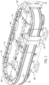
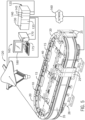
- an exemplary automated cart system for moving articles or products includes a track 10 made up of multiple segments 15, 20.
- the segments also referred to herein as "track segments" define a closed loop supporting movers 25 movable along the track 10.
- the track 10 is oriented in a horizontal plane and supported above the ground by a base 28 extending vertically downward from the track 10.
- the illustrated track 10 includes four straight segments 15, with two straight segments 15 located along each side of the track and spaced apart from the other pair.
- the track 10 also includes four curved segments 20 where a pair of curved segments 20 is located at each end of the track 10 to connect the pairs of straight segments 15.
- the four straight segments 15 and the four curved segments 20 form an oval track and define a closed surface over which each of the movers 25 may travel. It is understood that track segments of various sizes, lengths, and shapes may be connected together to form a track 10 and the track may include multiple branches or open-ended segments.
- each track segment 15, 20 is shown in a generally horizontal orientation.
- the track segments 15, 20 may also be oriented in a generally vertical orientation and the width of the track 10 may be greater in either the horizontal or vertical direction according to application requirements.
- the movers 25 will travel along the track and take various orientations according to the configuration of the track 10 and the relationships discussed herein.
- the exemplary construction shown has a transverse drive structure; other structures are possible including a planar drive structure.
- each track segment 15, 20 includes a number of independently attached rails on which each mover 25 runs.
- rails extend generally along the outer periphery of the track segment 15.
- Each track segment 15 includes a base portion 35 (two base portions 35 are shown in this construction), a channel portion 115, and a rail portion 40 (two rail portions 40 are shown in this construction).
- Each mover 25 includes complementary rollers 45 to engage the rail portions 40 for movement along the track 10.
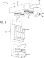
- Each mover 25 includes a side member 50, a top member 55, and a bottom member 60.
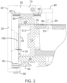
- the side member 50 is oriented parallel to a side surface 65 ( FIG. 2 ) when the mover 25 is mounted to the track 10.
- the top member 55 extends orthogonal to the side member 50 at a top end of the side member 50.
- the top member 55 includes a first segment 75, extending orthogonally from the side member 50.
- the top member 55 includes a set of rollers 45 that are mounted on the lower side of the first segment 75 and are configured to engage the rail portion 45 mounted to the top surface of the track segment 15.
- the bottom member 60 extends orthogonal to the side member 50 at a bottom end of the side member 50 and extends for a distance sufficient to receive a third pair of rollers 45 along the bottom of the mover 25.
- the third pair of rollers 45 engage an outer edge of the rail portion 45 mounted to the lower surface of the track segment 15.
- the top member 55 also includes a second segment 80 which protrudes from the first segment 75 an additional distance beyond the rail portion 40 and is configured to hold a position magnet 85.
- the position magnet 85 is mounted within a recess 90 on the second portion 75 and is configured to align with a sensor 95 mounted within the track segment 15.
- a linear drive system is incorporated in part on each mover 25 and in part within each track segment 15, 20 to control motion of each mover 25 along the segment.
- the linear drive system includes drive magnets 100 mounted to the side member 50.
- the drive magnets 100 are arranged in a block along an inner surface of the side member 50 with separate magnet segments alternately having a north pole, N, and south pole, S, facing the track segment 15.
- the drive magnets 100 are typically permanent magnets, and two adjacent magnet segments including a north pole and a south pole may be considered a pole-pair.
- the drive magnets 100 are mounted on the inner surface of the side member 50 and when mounted to the track 10 are spaced apart from a series of coils 105 extending along the track 10. As shown in FIG.
- an air gap 110 is provided between each set of drive magnets 100 and the coils 105 along the track 10.
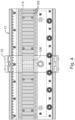
- the linear drive system includes a series of parallel coils 105 spaced along each track segment 15 as shown in FIG. 4 .
- each coil 105 is placed in a channel 115 extending longitudinally along one surface of the track segment 15. The electromagnetic field generated by each coil 105 spans the air gap 110 and interacts with the drive magnets 100 mounted to the mover 25 to control operation of the mover 25.
- An exemplary system controller 125 which may also be referred to herein as a motion controller, controls interaction between the robot 120 and movers 25 travelling along the track 10.
- the system controller 125 may be an industrial controller, referred to as a Programmable Logic Controller (PLC) or as a Programmable Automation Controller (PAC).
- PLC Programmable Logic Controller
- PAC Programmable Automation Controller
- the system controller 125 may include a power supply 130, a processor module 135, a communication module 140, and input and/or output (I/O) modules 145. It is contemplated that the system controller 125 may include a single rack or multiple racks of modules.
- a backplane extends between modules within a rack and backplane connectors on each module connect a module to the backplane to receive power and/or for communication between modules.
- the processor module includes a processor and a memory. It is contemplated that the processor and memory may each be a single electronic device or formed from multiple devices.
- the processor may be a microprocessor, and the memory may be a non-transitory storage medium.
- the processor and/or the memory may be integrated on a field programmable array (FPGA) or an application specific integrated circuit (ASIC).
- the memory may include volatile memory, non-volatile memory, or a combination thereof.
- the network module 140 facilitates connections to devices, remote racks, and/or other controllers located remotely from the system controller 125.
- Network medium connect the network module, for example, via an Ethernet connection to a network 160.
- the connection to the network 160 may be made directly or via a network device, such as a router, a switch, and the like.
- the network 160 may be an intranet, the Internet, or a combination thereof.
- the network 160 may be an industrial network such as EtherCAT, Profmet, DeviceNet, Ethernet I/P, ControlNet, and the like, may connect the network module 140 to other devices in the application.
- the network module 140 is also connected to a user interface 165, which may or may not be via the network 160.
- a set of I/O modules 145 connects the system controller 125 and the robot 120.
- Each of the I/O modules 145 may connect or disconnect from the backplane through a releasable electrical connector and may provide for one or more releasable terminals such as screw terminals or other electrical connectors allowing interconnection of the I/O modules 145 to conductors communicating with the robot 120.
- the user interface 165 is provided for an operator to configure the system controller 125 and to load or configure desired motion profiles for the movers 25 and the robot 120.
- the motion profiles can include configuration information for the track segments 15, 20, and logical axes (e.g., gains, limits, etc.) for the movers 25.
- the user interface 165 may include a processing unit 170, an input device 175, including, but not limited to, a keyboard, touchpad, mouse, trackball, or touch screen, and an output device 180, such as a display. It is contemplated that each component of the user interface 165 may be incorporated into a single unit, such as an industrial computer, laptop, or tablet computer. It is contemplated that other combinations of computing devices and peripherals as would be understood in the art may be utilized or incorporated into the system controller 125 and user interface 165
- a segment controller 200 is mounted within each track segment 15, 20.
- the segment controller 200 receives force command signals and generates switching signals for the drive 205 which, in turn, control activation of each coil 105.
- Activation of the coils 105 control and position each of the movers 25 along the track segment 15, 20 according to motion command signals originating from the system controller 125.
- the motion command signals are provided to one or more defined segment controllers for one or more movers 25, and the force command signals are provided from the defined segment controllers to the segment controller(s) the mover is located on.
- Communication circuitry (or module) in each segment controller 200 receives communication from the system controller 125 or other segment controllers 200 and passes the communication to a processor 215 and memory 220 executing in the segment controller 200.
- the communication circuitry is shown as being in two blocks 210A and 210B.
- the communication blocks 210A allow for connection to each other for all segments, and is connected to the system controller 125.
- the connections provide for a frontplane 233.
- the communication blocks 210B allow for connection to each other for all segments, and is not connected to the system controller 125.
- the connections provide for a backplane 235.
- the frontplane 233 and the backplane 235 and what is communicated over each plane will be discussed in more detail below.
- the processor 215 may be a microprocessor, and the memory 220 may be a non-transitory storage medium.
- the processor 215 and/or the memory 220 within the segment controller 200 may be integrated on a field programmable array (FPGA) or an application specific integrated circuit (ASIC). It is contemplated that the processor 215 and memory 220 may each be a single electronic device or formed from multiple devices.
- the memory 220 may include volatile memory, non-volatile memory, or a combination thereof.
- each segment controller 200 generates switching signals to control operation of switching devices within respective drives 205 mounted within the track segment 15, 20.
- the drive 205 within each track segment 15, 20 are connected between a DC supply 230 and the coils 105.
- the switching signals are generated to sequentially energize coils 205 along a track segment, where the energized coils 105 create an electromagnetic field that interacts with the drive magnets 100 on a mover 25 to control motion of the movers 25 along the corresponding track segment 15, 20.
- the switching signals control operation of switching devices in connection with the drive coils 105.
- the switching devices of the drive 205 may be solid-state devices that are activated by the switching signals, including, but not limited to, transistors, such as insulated-gate bipolar transistors (IGBTs) or metal-oxide semiconductor field-effect transistors (MOSFETs), thyristors, or silicon-controlled rectifiers.
- transistors such as insulated-gate bipolar transistors (IGBTs) or metal-oxide semiconductor field-effect transistors (MOSFETs), thyristors, or silicon-controlled rectifiers.
- the processor 215 also receives a feedback signal from the position sensors 95 along the track segments 15, 20 to provide an indication of the presence of one or more movers 25. While the position sensors 95 are shown as a single block, it is contemplated that the position sensors 95 typically includes multiple sensors and related conditioning circuitry. In each track segment 15, 20, the processor 215 can generate the switching signals to control the drive 205 to provide power to respective coils 105 for propelling a mover 25 while continuously receiving feedback signals for determining positions of the mover 25. The processor 215 also receives feedback signals from voltage and/or current sensors mounted at an input or output of the track segment 15, 20 providing an indication of the current operating conditions of a DC bus within the track segment 15, 20 or the operating conditions of a coil 50 connected to the track segment 15, 20.
- the system controller 125 provides coordinated motion for the system and is operative to generate motion commands for both the movers 25 along the track 10 and an external device, such as the illustrated robot. It is contemplated that the coordinated motion may be, for example, instruction(s) in a control program executing on the system controller 125. For example, the coordinated motion may be two or more instructions in the control program configured to generate motion of a mover 25 and the robot 120 in tandem with each other.
- the remote control architecture centralizes motion control responsibilities to one track segment (e.g., 15A) for a specific set of movers.
- This track segment 15A acts as a quasi-gateway when compared to prior systems.
- the track segment 15A (remote control "RC" segment) is responsible for motion control for its given mover 25 on an entire track 10 as the movers traverse the entire track.
- Individual track segments 10, 15 are responsible for managing the dynamic relationship between the movers 25 and the segments 10, 15 upon which they are located.
- Each track segment 15, 20 local control "LC” segment
- a track segment 15A can be both an RC track segment and an LC track segment.
- track segments 20A, 20B, and 15B are only LC track segments.
- a track segment 15, 20 requires computational capability as follows: force control based on segment physical capacity (e.g., 8 movers per one track segment in one implementation), and motion control based on track fill requirements, not segment physical capacity (e.g., 4 movers per one track segment).
- the description herein may refer to the RC track segment and the LC track segment as performing a function or operation.
- the segment controller 200 causes (e.g., through executing stored instructions) the RC or LC track segment to perform the function or operation.
- the backplane 235 is used to distribute force commands from RC segment(s) to LC segments (R2L packets) and collect position feedback from LC to RC segments (L2R packets).
- An R2L packet refers to a communication packet on the backplane 235 that originates at a remote control track segment, sent to a local control track segments.
- An L2R packet refers to a communication packet on the backplane 235 that originates at a local control track segment, sent to a remote control track segment.
- the backplane network communications are synchronized to a servo update rate and the backplane communications run at the servo update rate.
- FIG. 8 schematically shows the input to the RC segment as being a position reference signal (P*).
- the RC track segment includes a number of control loops, or regulators. Each control loop, or regulator, may include one or more controller gains and control paths, and is configured to provide a desired output according to a reference input.
- the RC track segment includes a position control loop, and a velocity control loop.
- the control loops are shown as cascading control loops where an output of one control loop is provided as an input to another control loop.
- the RC track segment also includes a feedforward path and a load observer. It is contemplated that various other control topologies may be utilized within the RC segment.
- the output of the RC track segment is a force command for a mover 25.
- Force control includes applying the force command to a mover 25 by determining and applying the necessary current in the appropriate coil(s) 105 that affects force production for that mover 25.
- FIG. 8 shows the force command being translated to a current reference signal (I*) provided to a current regulator 120.
- the current regulator 120 uses the current reference signal (I*) and a current feedback signal (I fdbk ), generated by a current sensors to regulate a current regulator output signal to a desired value.
- the current regulator output signal is a voltage reference signal for the gate driver 60 which, in turn, generates the switching signals 31 to the drive section 205.
- the position feedback device 44 generates the position feedback signal (P fdbk ) used by the control module 55.
- FIG. 8 provides a simple example of a motion command being provided to an RC track segment, which then provides a force command to an LC track segment.
- ICT has many carts moving concurrently and may be part of a larger motion system
- the actual generating of the motion commands and force commands is likely more complex than is shown.
- the techniques used to generate the motion and force commands can vary depending on the design of the ICS. It is envisioned, though, that motion control includes fine interpolation, position control, velocity control, load observer(s), and/or filtering (low pass, notch, etc.).
- the output of motion control is a force command for a mover.
- Force control includes applying the force command to an LC track segment by determining and applying the necessary current in the appropriate coil(s) that affects force production for that mover 25. Force control may also include a current regulator for each coil. A force feedback estimate may be provided which would be calculated by using the coil current feedback and inverse commutation tables.
- FIG. 9 is a snapshot in time for a track having two RC track segments, four LC track segments (only two shown), and eight movers. The figure only shows the RC and LC functions for simplicity.
- System controller 125 has fixed motion connections to RC1 and RC2.
- RC1 and RC2 manage gaps between segments by duplicating communications as mover approaches a gap. For example, communication for mover M7 is communicated to both LC1 and LC2.
- Communication among RC1-RC2 and LC1-LC4 is over the backplane 230.
- PKT refers to a communication packet from RC1-RC2 to LC1-LC4 or vice-versa.
- Servo control has sampling synchronized to the servo loop execution. This implies that the R2L and L2R communications should be synchronized to the servo update period and PWM signal. For a small track implementation (e.g., sixteen or less track segments), servo updates over the entire track and hence, R2L and L2R communications, are concentrated on the backplane.
- the track communication architecture can support staggering servo updates, which may increase backplane utilization. Staggering every other RC segment to run one-half servo update period (SUP) increases backplane utilization and can increase track size and/or mover count.
- SUP servo update period
- Backplane latency affects track size and mover count.
- the operator assigns maximum movers per track segment to combine multiple mover data in a single packet. This can result in less packets on the backplane 230.
- the backplane is specifically designed as a communication line; i.e., the first and last segments are not communicatively connected. Defining track segments in the middle of the track as RCs reduces the number of hops for R2L and L2R communications, thereby reducing latency.
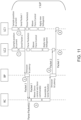
- the sequence diagrams of FIGs. 10 and 11 illustrate the relationship between remote control and local control segments.
- the sequence diagrams start with an LC sampling position and current. The diagrams do not show how the RC segment manages the communications. The sequence diagrams also ignore that the RC track segment may also be an LC track segment for simplicity. When the LC track segment is the same track segment as the RC track segment, no external communication is required.
- the first figure shows a single LC track segment, and the second figure shows two LC track segments.
- "BP" is the backplane in Figs. 10 and 11 .
- the entire sequence shown occurs in one servo update period (SUP). The sequence steps are described below.
- LC track segments sample position and current. Position sampling can occur using time synchronization so that position samples occur at a known time reference with the SUP. RC track segments should know the position sample reference time and not require a time stamp to be sent in the packet.
- Using a (Common Industrial Protocol) CIP Sync object and a PTP (Precision time protocol) time synchronization enables synchronized sampling on all track segments 15, 20.
- Another implementation includes sending a single time stamp in a packet corresponding to a specific time reference of the position sampling on the LC track segment. All track segments can have a map of mover IDs and the associated RC track segments perform motion control for each mover 25.
- An LC track segment assembles an L2R packet of data for each RC track segment associated with the movers' 25 resident on the LC track segment. Each packet includes all data for all movers 25 on the LC track segment controlled by that RC track segment.
- FIG. 9 illustrates the relationship between movers, LC track segments and RC track segments.
- RC1 is responsible for M1-M4 and RC2 is responsible for movers M5-M8.
- LC1 has to create a packet for RC1 with M4 data.
- LC1 also has to create a packet for movers M5, M6 for RC2. All the movers on LC2 are associated with RC2, so LC2 creates a single packet with data for both movers.
- An exemplary list of data in a packet may include one or more of the following: mover count (number of movers in the packet); mover ID(s); incremental position change(s) (velocity, for motion control); force feedback estimate(s); a limited set of real time read attribute data; LC track segment status (segment fault active, current regulator saturation/limiting, etc.); and a time stamp for position capture.
- each packet traverses the backplane 230.
- the time required for packet transmission and receipt is trivial for these examples, but becomes more significant for larger tracks with many packets.
- a backplane throughput can be a critical design metric to scale up to large tracks.
- the LC track segment Upon the LC track segment sending the L2R packet over the backplane 230, the LC track segment parses R2L packets with command information for all the movers that it controls locally. The LC track segment performs commutation, current regulation on each individual coil, and ultimately applies new coil voltages.
- the RC track segment receives and parses packets for all the movers 25 that it controls.
- the RC track segment performs motion control for all movers resulting in force commands.
- the RC track segment can execute the motion control on all axes in succession to optimize cache memory access, so all the mover feedback data should be parsed and ready before unleashing the motion control algorithms.
- the RC track segment assembles an R2L packet of data for each LC track segment with resident movers that it controls. The packet can include all data for all movers on the LC track segment controlled by that RC track segment.
- An exemplary list of data in a packet may include one or more of the following: mover count (number of movers in packet); mover ID; force command (Direct force control, or Vreg output); adjacent mover absolute position (commutation angle for mover hand off between LC track segments); adjacent mover velocity (commutation angle advance for mover hand off between LC track segments); and a limited set of real time write attribute data.
- the LC track segment receives R2L packets with command information for all the movers that it controls locally.
- the R2L packets are queued for the next SUP cycle.
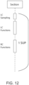
- FIG. 12 illustrates how a track segment fulfills the roles of RC and LC.
- the RC and LC functions are time shifted within a SUP and don't overlap. 55
- the time spent on the RC/LC functions cannot consume the entire SUP as a track segment has other responsibilities such as Ethernet/CIP stack, Axis State Machine, DC bus control, etc.
- a track that is entirely filled with movers is typically not useful.
- a track fill ratio can be defined as the ratio of the maximum number of movers allowed on a track to the number of movers that can physically fit on a track.
- An example fill ratio would be 0.5 corresponding to 1 ⁇ 2 the track being filled with movers.
- a benefit of the RC architecture is that sections do not have to provide the motion control capacity corresponding to the maximum number of movers that can fit on the section. Each section should be able to perform motion control for a number of movers corresponding to the track fill ratio. Motion control is evenly distributed across all sections on a track and not concentrated at any section based on the number of movers on that can fit on the section. Each section does have to have the force control capacity corresponding to the maximum number of movers that can be located on the section.
- servo performance would be identical across the gaps, but this is difficult for at least the following reasons: 1) the gap creates a discontinuity in the drive coils and feedback system; 2) force control should be managed by the two track segments on each side of the gap; 3) when a mover approaches a new track segment, the new track segment cannot detect position of the mover, but it has to participate in force control; 4) when a mover is close to the gap, both segments detect position, but the detected positions can differ.
- Remote Control segments are responsible for mover position control, force command generation and communication with local control track segments. Therefore, RC track segments should manage the mover hand off.
- FIG. 9 illustrates how an RC track segment would manage mover handoff to a receiving LC track segment.
- the RC track segment responsible for the mover starts sending mover position and force command to the new LC track segment to which the mover will transition.
- the RC can determine the segment position to initiate this communication based on the mover speed and segment SUP.
- Another strategy is to always send position and force data to the adjacent track segment as it will do no harm when the mover is not in a position where the receiving track segment can apply any force.
- RC track segments should send the position received from one LC track segment (LC2 in this example) to the receiving track segment (LC1 in this example). Receiving LC track segments will get position data that corresponds to the same update as the force command (refer to FIG. 11 ).
- a method of centralizing motion control responsibility and distributing force control responsibility on track based systems is disclosed. The method provides a single controller interface communication point.
Landscapes
- Engineering & Computer Science (AREA)
- Mechanical Engineering (AREA)
- Automation & Control Theory (AREA)
- Physics & Mathematics (AREA)
- General Physics & Mathematics (AREA)
- Remote Sensing (AREA)
- Radar, Positioning & Navigation (AREA)
- Aviation & Aerospace Engineering (AREA)
- Evolutionary Computation (AREA)
- Business, Economics & Management (AREA)
- Health & Medical Sciences (AREA)
- Artificial Intelligence (AREA)
- Transportation (AREA)
- Game Theory and Decision Science (AREA)
- Medical Informatics (AREA)
- Quality & Reliability (AREA)
- Manufacturing & Machinery (AREA)
- General Engineering & Computer Science (AREA)
- Linear Motors (AREA)
- Control Of Position, Course, Altitude, Or Attitude Of Moving Bodies (AREA)
Claims (13)
- Verfahren zum Steuern des Betriebs einer Vielzahl von Bewegern (25), die sich entlang eines automatisierten, unabhängigen Wagensystems bewegen, wobei das System eine Schiene (10) mit einer Vielzahl von Schienensegmenten (15, 20) umfasst, wobei jedes Schienensegment eine jeweilige Steuerung (200) aufweist, wobei das Verfahren die folgenden Schritte umfasst:Empfangen eines Bewegungsbefehls für einen ersten Beweger (25) an einer ersten Steuerung (200) eines ersten Schienensegments (15A), wobei die erste Steuerung für den ersten Beweger über die gesamte Schiene verantwortlich ist;Empfangen einer Positionsrückmeldung an der ersten Steuerung von einer zweiten Steuerung (200) eines zweiten Schienensegments (15B, 20A, 20B) an beliebiger Stelle entlang der Schiene, die einer Position des ersten Bewegers auf dem zweiten Schienensegment entspricht;Bestimmen, an der ersten Steuerung, eines Kraftbefehls für den ersten Beweger auf dem zweiten Schienensegment, basierend auf dem Bewegungsbefehl und der Positionsrückmeldung, und Senden des bestimmten Kraftbefehls für den ersten Beweger an die zweite Steuerung die das zweite Schienensegment steuert; undErzeugen eines Erregungsfeldes an der zweiten Steuerung (200), um mit einem Magneten (100) des ersten Bewegers basierend auf dem empfangenen Kraftbefehl zu interagieren.
- Verfahren nach Anspruch 1, und ferner umfassend:Empfangen eines zweiten Bewegungsbefehls für einen zweiten Beweger an der ersten Steuerung;Empfangen einer zweiten Positionsrückmeldung an der ersten Steuerung, die einer zweiten Position für den zweiten Beweger entlang der Schiene entspricht;Bestimmen eines zweiten Kraftbefehls auf der Grundlage des zweiten Bewegungsbefehls und der zweiten Positionsrückmeldung; undErzeugen eines zweiten Erregungsfeldes zur Wechselwirkung mit einem zweiten Magneten des zweiten Bewegers auf der Grundlage des zweiten Kraftbefehls.
- Verfahren nach Anspruch 2, und ferner umfassend:Empfangen eines dritten Bewegungsbefehls für einen dritten Beweger an einer zweiten Steuerung für ein zweites Schienensegment;Empfangen einer dritten Positionsrückmeldung an der zweiten Steuerung, die einer dritten Position für den dritten Beweger entlang der Schiene entspricht;Bestimmen eines dritten Kraftbefehls auf der Grundlage des dritten Bewegungsbefehls und der dritten Positionsrückmeldung; undErzeugen eines dritten Erregungsfeldes zur Wechselwirkung mit einem dritten Magneten des dritten Bewegers auf der Grundlage des dritten Kraftbefehls.
- Verfahren nach einem der Ansprüche 1 bis 3, und ferner umfassend:Übermitteln des Bewegungsbefehls von einer von der Bahn getrennten Systemsteuerung an die erste Steuerung;Übermitteln eines zweiten Befehls von der Systemsteuerung an einen von der Schiene getrennten Aktuator, wodurch eine Aktion des Aktuators mit der Erregung des Bewegers bewirkt wird.
- Verfahren nach einem der Ansprüche 1 bis 4, das ferner Folgendes umfasst:Übermittlung der Positionsrückmeldung von einem zweiten Schienensegment mit dem zweiten Regler;wobei die empfangene Positionsrückmeldung mit der übermittelten Positionsrückmeldung übereinstimmt.
- Verfahren nach einem der Ansprüche 1 bis 5, mit mindestens einem der folgenden Schritte:wobei das Erzeugen eines Erregerfeldes das Identifizieren einer oder mehrerer zu erregender Spulen und das Verursachen eines Stroms durch die identifizierte(n) Spule(n) umfasst;wobei das Verfahren ferner das Erzeugen eines zweiten Erregungsfeldes an der ersten Steuereinheit umfasst, um mit dem Magneten der Bewegungsvorrichtung auf der Grundlage des Kraftbefehls zu interagieren; undwobei das System ferner eine Rückwandplatine enthält, die die jeweiligen Steuerungen der mehreren Schienensegmente kommunikativ koppelt, und wobei das Verfahren ferner das Kommunizieren der Positionsrückmeldung und des Kraftbefehls über die Rückwandplatine umfasst.
- Das Verfahren nach einem der Ansprüche 1 bis 6, und ferner umfassend:Empfangen einer Mehrzahl von Bewegungsbefehlen für eine erste Mehrzahl von Bewegern, einschließlich des ersten Bewegers, an der ersten Steuerung;Empfangen, an der ersten Steuerung, einer Vielzahl von Positionsrückmeldungen, die einer Vielzahl von jeweiligen Orten entlang der Strecke für die erste Vielzahl von Bewegern entsprechen, wobei die Vielzahl von Positionsrückmeldungen die Positionsrückmeldung enthält, die einem Ort für den ersten Beweger entlang der Schiene entspricht;Bestimmen einer Mehrzahl von Kraftbefehlen für die Mehrzahl erster Beweger jeweils auf der Grundlage der Mehrzahl von Bewegungsbefehlen und der Mehrzahl von Positionsrückmeldungen an der ersten Steuerung, wobei die Mehrzahl von Kraftbefehlen den Kraftbefehl für den ersten Beweger enthält;Übermitteln der Mehrzahl von Kraftbefehlen an die Mehrzahl von Steuerungen auf der Grundlage der Positionsrückmeldungen; undErzeugen einer Vielzahl von Erregungsfeldern zum Zusammenwirken mit der Vielzahl von Bewegern auf der Grundlage der Vielzahl von Kraftbefehlen,wobei die erste Mehrzahl von Bewegern kleiner ist als eine Gesamtzahl der Mehrzahl von Bewegern auf der Strecke.
- Ein automatisiertes unabhängiges Wagensystem, das Folgendes umfasst:einen Beweger (25) mit mindestens einem Antriebsmagneten (100);ein oder mehrere erste Schienensegmente (15B, 20A, 20B), wobei jedes Schienensegment des einen oder der mehreren ersten Schienensegmente jeweils Folgendes umfassteine erste Mehrzahl von Antriebsspulen (105),einen ersten Antrieb, der mit der ersten Vielzahl von Antriebsspulen gekoppelt ist, undeine erste Steuerung, die mit dem ersten Antrieb gekoppelt ist, wobei die erste Steuerung dazu dient, den ersten Antrieb selektiv zu steuern, um die erste Mehrzahl von Antriebsspulen zu erregen, um ein erstes elektromagnetisches Feld aufzubauen, das mit dem mindestens einen Antriebsmagneten der Bewegungsvorrichtung wechselwirkt; undein zweites Schienensegment (15A) mit:eine zweite Mehrzahl von Antriebsspulen,einen zweiten Antrieb, der mit der zweiten Vielzahl von Antriebsspulen gekoppelt ist, undeine zweite Steuerung, die mit dem zweiten Antrieb gekoppelt ist und für den Beweger über eine gesamte Spur (10), das zweite Spursegment, verantwortlich ist, wobei die zweite Steuerung betriebsfähig ist, um selektiv den zweiten Antrieb zu steuern, um die zweite Mehrzahl von Antriebsspulen zu erregen, um ein zweites elektromagnetisches Feld aufzubauen, um mit dem mindestens einen Antriebsmagneten des Bewegers zu interagieren, wobei der zweite Prozessor ferner betreibbar ist, um von einem gegebenen Schienensegment des einen oder der mehreren ersten Schienensegmente eine Positionsrückmeldung zu empfangen, die sich auf eine Position des Bewegers auf dem gegebenen Schienensegment bezieht, um einen Kraftbefehl für den Beweger auf dem gegebenen Schienensegment auf der Grundlage der ersten Positionsrückmeldung zu erzeugen, und um den Kraftbefehl für den Beweger an die Steuerung welche das gegebene Schienensegment steuert, zu senden,wobei die erste Steuerung und die zweite Steuerung selektiv den ersten und zweiten Antrieb auf der Grundlage des Kraftbefehls steuern.
- Automatisiertes unabhängiges Wagensystem nach Anspruch 8, ferner umfassendeinen zweiten Beweger (25) mit mindestens einem zweiten Antriebsmagneten;ein drittes Schienensegment (15B, 20A, 20B) mit:eine dritte Mehrzahl von Antriebsspulen,einen dritten Antrieb, der mit der dritten Vielzahl von Antriebsspulen gekoppelt ist, undeine dritte Steuerung, die mit dem dritten Antrieb gekoppelt ist, wobei die dritte Steuerung ein drittes nicht-übertragbares Speichermedium, das zum Speichern einer dritten Mehrzahl von Befehlen konfiguriert ist, und einen dritten Prozessor in Kommunikation mit dem dritten nicht-übertragbaren Speichermedium enthält, wobei der dritte Prozessor betriebsfähig ist, um die dritte Mehrzahl von Anweisungen auszuführen, um den dritten Antrieb selektiv zu steuern, um die dritte Mehrzahl von Antriebsspulen zu erregen, um ein drittes elektromagnetisches Feld aufzubauen, um mit dem mindestens einen Antriebsmagneten des ersten Bewegers in Wechselwirkung zu treten und um mit dem mindestens einen Antriebsmagneten des zweiten Bewegers in Wechselwirkung zu treten, wobei der dritte Prozessor ferner betriebsfähig ist, um eine zweite Positionsrückmeldung zu empfangen, die sich auf eine zweite Position des zweiten Bewegers bezieht, und einen zweiten Kraftbefehl basierend auf der zweiten Positionsrückmeldung zu erzeugen,wobei die erste Steuereinheit, die zweite Steuereinheit und die dritte Steuereinheit selektiv den ersten, zweiten und dritten Antrieb auf der Grundlage des zweiten Kraftbefehls steuern.
- Automatisiertes unabhängiges Wagensystem nach Anspruch 8 oder 9,wobei das System ferner eine Vielzahl von Bewegern umfasst, wobei jeder der Vielzahl von Bewegern mindestens einen Antriebsmagneten aufweist, undwobei der erste Prozessor ferner betriebsfähig ist, die Mehrzahl von Befehlen auszuführen, um den ersten Antrieb selektiv zu steuern, um die erste Mehrzahl von Antriebsspulen zu erregen, um elektromagnetische Felder aufzubauen, die mit dem mindestens einen Antriebsmagneten der Mehrzahl von Bewegern wechselwirken.
- Automatisiertes unabhängiges Wagensystem nach Anspruch 10, wobei der zweite Prozessor ferner betriebsfähig ist, die Mehrzahl von Befehlen auszuführen, um den zweiten Antrieb selektiv zu steuern, um die zweite Mehrzahl von Antriebsspulen zu erregen, um ein zweites elektromagnetisches Feld aufzubauen, um mit dem mindestens einen Antriebsmagneten der Mehrzahl von Bewegern in Wechselwirkung zu treten, wobei der zweite Prozessor ferner betriebsfähig ist, Positionsrückmeldungen zu empfangen, die sich auf Positionen der Mehrzahl von Bewegern beziehen, und Kraftbefehle auf der Grundlage der Positionsrückmeldungen zu erzeugen, und wobei die ersten Steuerungen und die zweite Steuerung den ersten und den zweiten Antrieb auf der Grundlage der Kraftbefehle selektiv steuern.
- Automatisiertes unabhängiges Wagensystem nach einem der Ansprüche 8 bis 11, wobei das System ferner eine Rückwandplatine umfasst, die die jeweiligen Steuerungen der mehreren Schienensegmente kommunikativ koppelt, wobei die kommunikative Kopplung die Kommunikation der Positionsrückmeldungen und des Kraftbefehls über die Rückwandplatine umfasst.
- Ein Automatisierungssystem, das Folgendes umfasst:einen Aktuator (120);das automatisierte unabhängige Wagensystem nach einem der Ansprüche 8 bis 12; undeine Bewegungssteuerung (125), die mit dem Stellglied und dem automatisierten unabhängigen Wagensystem gekoppelt ist, wobei die Bewegungssteuerung einen Bewegungsbefehl erzeugt und einen Stellgliedbefehl übermittelt, der eine Aktion des Stellglieds bewirkt,wobei der Kraftbefehl ferner auf dem Bewegungsbefehl basiert.
Applications Claiming Priority (1)
| Application Number | Priority Date | Filing Date | Title |
|---|---|---|---|
| US16/184,389 US10967892B2 (en) | 2018-11-08 | 2018-11-08 | Independent cart system and method of operating the same |
Publications (2)
| Publication Number | Publication Date |
|---|---|
| EP3650971A1 EP3650971A1 (de) | 2020-05-13 |
| EP3650971B1 true EP3650971B1 (de) | 2024-06-05 |
Family
ID=68501431
Family Applications (1)
| Application Number | Title | Priority Date | Filing Date |
|---|---|---|---|
| EP19208005.9A Active EP3650971B1 (de) | 2018-11-08 | 2019-11-08 | Unabhängiges wagensystem und verfahren zum betrieb davon |
Country Status (2)
| Country | Link |
|---|---|
| US (2) | US10967892B2 (de) |
| EP (1) | EP3650971B1 (de) |
Families Citing this family (11)
| Publication number | Priority date | Publication date | Assignee | Title |
|---|---|---|---|---|
| US10587212B1 (en) * | 2018-11-12 | 2020-03-10 | Rockwell Automation Technologies, Inc. | Linear motor track system with automatic gravity detection |
| DE102019002424A1 (de) * | 2019-04-03 | 2020-10-08 | Günther Zimmer | Umsetzvorrichtung eines Transportsystems |
| US20220080873A1 (en) * | 2020-09-15 | 2022-03-17 | Hall Labs Llc | Package Delivery System with Robots for Last Distance |
| US20240317513A1 (en) * | 2021-08-05 | 2024-09-26 | Tetra Laval Holdings & Finance S.A. | A linear motor system, corresponding forming assembly and method |
| US12024372B2 (en) * | 2021-09-20 | 2024-07-02 | Quest Industrial LLC | System and method for handling and evaluating products packaged in flexible bags |
| EP4201854A1 (de) | 2021-12-22 | 2023-06-28 | Fameccanica.Data S.p.A. | Förderverfahren, -einheit und -vorrichtung zur formatänderung für verpackungsanlagen |
| US12005941B2 (en) | 2022-04-27 | 2024-06-11 | Rockwell Automation Technologies, Inc. | System and method for controlling movers in an independent cart system during heavy traffic |
| US11831182B1 (en) | 2022-08-16 | 2023-11-28 | Rockwell Automation Technologies, Inc. | System and method for in-line wireless energy transfer and sensing in an independent cart system |
| US20240059327A1 (en) | 2022-08-16 | 2024-02-22 | Rockwell Automation Technologies, Inc. | System and Method for Mover Self-Navigation in an Independent Cart System |
| KR102790349B1 (ko) * | 2022-11-11 | 2025-04-04 | 세메스 주식회사 | 이송 장치 |
| US12121936B1 (en) | 2023-05-31 | 2024-10-22 | General Mills, Inc. | Processing system for handling pieces of product |
Family Cites Families (43)
| Publication number | Priority date | Publication date | Assignee | Title |
|---|---|---|---|---|
| US6191507B1 (en) * | 1997-05-02 | 2001-02-20 | Ats Automation Tooling Systems Inc. | Modular conveyor system having multiple moving elements under independent control |
| US6983701B2 (en) * | 2001-10-01 | 2006-01-10 | Magnemotion, Inc. | Suspending, guiding and propelling vehicles using magnetic forces |
| US6637586B1 (en) * | 2002-02-15 | 2003-10-28 | Leap Frog Systems, Inc. | Accumulating pallet conveyor and storage system |
| US9102336B2 (en) * | 2002-10-16 | 2015-08-11 | Cross Belt Ip, L.L.C. | Portable bin for sortation system |
| EP1779208A2 (de) * | 2004-08-04 | 2007-05-02 | Siemens Energy & Automation, Inc. | Integrierte steuerkarte für beförderungssysteme |
| US7591366B2 (en) * | 2005-06-07 | 2009-09-22 | Hytrol Conveyor Company, Inc. | Conveyor system and method for accumulating packages of varying lengths |
| US7421193B2 (en) * | 2005-06-28 | 2008-09-02 | Kobayashi Herbert S | Digital motor control system and method |
| US20070261941A1 (en) * | 2006-05-10 | 2007-11-15 | Dematic Corp. | Dynamic motorized roller conveyor control |
| US8074578B2 (en) * | 2006-07-05 | 2011-12-13 | Magnemotion, Inc. | Linear synchronous motor power control system and methods |
| WO2008008716A2 (en) * | 2006-07-10 | 2008-01-17 | Dematic Corp. | Conveyor system with dynamic gapping and method of slug building |
| US7806254B2 (en) * | 2006-09-25 | 2010-10-05 | Dematic Corp. | Belt conveyor and method |
| NL2000266C2 (nl) * | 2006-10-09 | 2008-04-10 | Specialty Conveyor Bv | Transporteur voor het transporteren en bufferen van stukgoederen. |
| US8050795B2 (en) * | 2007-03-20 | 2011-11-01 | Donald L. Dollens | Conveyor drive control system |
| DE102007040367B4 (de) * | 2007-08-17 | 2022-11-17 | Ssi Schäfer Automation Gmbh | Materialflusssteuerung zur Kollisionsvermeidung in einer Förderanlage |
| US9032880B2 (en) * | 2009-01-23 | 2015-05-19 | Magnemotion, Inc. | Transport system powered by short block linear synchronous motors and switching mechanism |
| US8616134B2 (en) * | 2009-01-23 | 2013-12-31 | Magnemotion, Inc. | Transport system powered by short block linear synchronous motors |
| DE102009003475A1 (de) * | 2009-02-12 | 2010-08-19 | Krones Ag | Förderer und Verfahren zum Beschicken einer Weiterverarbeitungseinheit |
| US8284993B2 (en) * | 2009-06-18 | 2012-10-09 | Hytrol Conveyor Company, Inc. | Decentralized tracking of packages on a conveyor |
| US20120024669A1 (en) * | 2010-07-29 | 2012-02-02 | Danelski Darin L | Networked Motorized Drive Roller Conveyor |
| US8887897B2 (en) * | 2010-08-31 | 2014-11-18 | Itoh Denki Co., Ltd. | Fault diagnosis method for roller conveyor, roller conveyor, and controller for conveyor |
| EP2691319B1 (de) * | 2011-03-31 | 2022-05-25 | ATS Automation Tooling Systems Inc. | Positionseinstellsystem für paletten |
| US8757363B2 (en) * | 2011-05-09 | 2014-06-24 | Insight Automation, Inc. | Conveyor controllers |
| WO2012170636A1 (en) * | 2011-06-07 | 2012-12-13 | Magnemotion, Inc. | Versatile control of a linear synchronous motor propulsion system |
| JP5753060B2 (ja) * | 2011-11-07 | 2015-07-22 | ヤマハ発動機株式会社 | リニアコンベア及びその駆動制御方法 |
| DE102012204916A1 (de) * | 2012-03-27 | 2013-10-02 | Beckhoff Automation Gmbh | Statorvorrichtung für einen Linearmotor und lineares Transportsystem |
| JP6335603B2 (ja) * | 2014-04-15 | 2018-05-30 | キヤノン株式会社 | 台車搬送システム |
| EP3148904B1 (de) * | 2014-06-02 | 2021-05-05 | ATS Automation Tooling Systems Inc. | System und verfahren zur verfolgung eines beweglichen elements in einem linearen motorfördersystem |
| EP3024128B1 (de) | 2014-11-18 | 2018-04-25 | Siemens Aktiengesellschaft | Modulare Steuerung eines Linearantriebs mit Kommunikation |
| WO2016118865A1 (en) * | 2015-01-23 | 2016-07-28 | Dreamwell, Ltd. | Automated mattress manufacturing process and apparatus |
| US20160260142A1 (en) * | 2015-03-06 | 2016-09-08 | Wal-Mart Stores, Inc. | Shopping facility assistance systems, devices and methods to support requesting in-person assistance |
| US9812939B2 (en) * | 2015-08-21 | 2017-11-07 | Murata Machinery, Ltd. | Linear motor system |
| EP3173186A1 (de) | 2015-11-24 | 2017-05-31 | Siemens Aktiengesellschaft | Maschinenstation mit einem linearantrieb, anlage und verfahren zur bearbeitung eines bearbeitungsgutes |
| GB2566815B (en) * | 2016-02-04 | 2021-11-03 | Walmart Apollo Llc | Vehicle systems and methods to support the distribution of products |
| AT518270B1 (de) * | 2016-02-05 | 2017-09-15 | Bernecker + Rainer Industrie-Elektronik Ges M B H | Verfahren zum Steuern der Bewegung einer Antriebsachse einer Antriebseinheit |
| ITUB20161148A1 (it) * | 2016-02-29 | 2017-08-29 | Vismunda Srl | Sistema di movimentazione a navette indipendenti e coordinate, per automazione industriale |
| ITUB20161142A1 (it) * | 2016-02-29 | 2017-08-29 | Vismunda Srl | Metodo e impianto produttivo automatico per la stampa su celle fotovoltaiche. |
| US10108193B2 (en) * | 2016-05-27 | 2018-10-23 | Glen C Wernersbach | Mover system |
| US10256023B2 (en) * | 2016-09-29 | 2019-04-09 | Rockwell Automation Technologies, Inc. | Method and apparatus for interleaved switching of track segments in a motion control system |
| US10442637B2 (en) * | 2017-09-21 | 2019-10-15 | Magnemotion, Inc. | Linear drive system having central, distributed and group control |
| US10261491B1 (en) * | 2018-03-05 | 2019-04-16 | Rockwell Automation Technologies, Inc. | Method and apparatus for coordinating external device motion with motion of independent movers in a linear drive system |
| US10919705B2 (en) * | 2018-05-29 | 2021-02-16 | The Procter And Gamble Company | Apparatus that controls motion of independent movers along a path |
| US10696488B2 (en) * | 2018-05-29 | 2020-06-30 | The Procter And Gamble Company | Apparatus that controls motion of proximate independent movers along a path |
| EP3953282A4 (de) * | 2019-04-08 | 2022-11-30 | Lineage Logistics, LLC | Automatischer transport von warenpaletten |
-
2018
- 2018-11-08 US US16/184,389 patent/US10967892B2/en active Active
-
2019
- 2019-11-08 EP EP19208005.9A patent/EP3650971B1/de active Active
-
2021
- 2021-03-26 US US17/213,589 patent/US11643120B2/en active Active
Also Published As
| Publication number | Publication date |
|---|---|
| US11643120B2 (en) | 2023-05-09 |
| US20210213984A1 (en) | 2021-07-15 |
| US10967892B2 (en) | 2021-04-06 |
| US20200148239A1 (en) | 2020-05-14 |
| EP3650971A1 (de) | 2020-05-13 |
Similar Documents
| Publication | Publication Date | Title |
|---|---|---|
| EP3650971B1 (de) | Unabhängiges wagensystem und verfahren zum betrieb davon | |
| EP3537247B1 (de) | Verfahren und vorrichtung zur koordinierung der bewegung einer externen vorrichtung mit der bewegung von unabhängigen bewegungsvorrichtungen in einem linearantriebssystem | |
| EP3929025B1 (de) | Linearantriebssystem mit zentraler, verteilter und gruppensteuerung | |
| US10566917B2 (en) | Linear motor control apparatus and linear motor control system | |
| US10717365B2 (en) | System and method for limiting motion in an independent cart system | |
| US11851093B2 (en) | Section based safety functions for independent cart applications | |
| US8843232B2 (en) | Control method for a complex consisting of a plurality of multiaxial handling devices arranged in succession and/or side by side, and also data storage medium, control system and complex | |
| US11912508B2 (en) | Method for controlling a transport unit of a transport device in the form of a long-stator linear motor | |
| US20190092572A1 (en) | Conveyance apparatus, conveyance system, and method of controlling conveyance system | |
| CN110457245B (zh) | 输送系统 | |
| US11599101B2 (en) | Independent mover transport system and method of extending range of operations in an independent mover transport system | |
| US11413968B2 (en) | Method and apparatus for providing improved motion control of movers in an independent cart system | |
| US10983508B2 (en) | Automated independent cart system and method of controlling operation of a plurality of movers of the automated independent cart system | |
| JP5623039B2 (ja) | 動的に可変の駆動範囲を有する搬送装置 | |
| JP2010064897A6 (ja) | 動的に可変の駆動範囲を有する搬送装置 | |
| JP2025023077A (ja) | 搬送システム、制御システム及び制御方法 | |
| JP7083963B2 (ja) | リニアコンベアシステム、リニアコンベアシステムの制御方法、リニアコンベアシステムの制御プログラムおよび記録媒体 | |
| Wu et al. | Iterative learning variable structure controller for high-speed and high-precision point-to-point motion | |
| CN113748075A (zh) | 线性输送机系统、线性输送机系统的控制方法、线性输送机系统的控制程序以及记录介质 | |
| CN119731100A (zh) | 货物传输系统,控制单元,构造套件,模拟程序产品和平面马达的主动构件的应用 | |
| US20250243007A1 (en) | Bump-less Transition Between Trajectory Changes | |
| EP4632514A1 (de) | Virtuelle slots für unabhängiges wagensystem | |
| EP4393857A1 (de) | System und verfahren zur betätigung in einem linearmotorfördersystem | |
| KR20250143012A (ko) | 무빙 마그넷 캐리어를 이용한 물품 이송 방법 및 이송시스템 | |
| CN120936554A (zh) | 线性输送机装置及线性输送机装置的控制方法 |
Legal Events
| Date | Code | Title | Description |
|---|---|---|---|
| PUAI | Public reference made under article 153(3) epc to a published international application that has entered the european phase |
Free format text: ORIGINAL CODE: 0009012 |
|
| STAA | Information on the status of an ep patent application or granted ep patent |
Free format text: STATUS: THE APPLICATION HAS BEEN PUBLISHED |
|
| AK | Designated contracting states |
Kind code of ref document: A1 Designated state(s): AL AT BE BG CH CY CZ DE DK EE ES FI FR GB GR HR HU IE IS IT LI LT LU LV MC MK MT NL NO PL PT RO RS SE SI SK SM TR |
|
| AX | Request for extension of the european patent |
Extension state: BA ME |
|
| STAA | Information on the status of an ep patent application or granted ep patent |
Free format text: STATUS: REQUEST FOR EXAMINATION WAS MADE |
|
| 17P | Request for examination filed |
Effective date: 20201023 |
|
| RBV | Designated contracting states (corrected) |
Designated state(s): AL AT BE BG CH CY CZ DE DK EE ES FI FR GB GR HR HU IE IS IT LI LT LU LV MC MK MT NL NO PL PT RO RS SE SI SK SM TR |
|
| STAA | Information on the status of an ep patent application or granted ep patent |
Free format text: STATUS: EXAMINATION IS IN PROGRESS |
|
| 17Q | First examination report despatched |
Effective date: 20211021 |
|
| GRAP | Despatch of communication of intention to grant a patent |
Free format text: ORIGINAL CODE: EPIDOSNIGR1 |
|
| STAA | Information on the status of an ep patent application or granted ep patent |
Free format text: STATUS: GRANT OF PATENT IS INTENDED |
|
| INTG | Intention to grant announced |
Effective date: 20240105 |
|
| GRAS | Grant fee paid |
Free format text: ORIGINAL CODE: EPIDOSNIGR3 |
|
| GRAA | (expected) grant |
Free format text: ORIGINAL CODE: 0009210 |
|
| STAA | Information on the status of an ep patent application or granted ep patent |
Free format text: STATUS: THE PATENT HAS BEEN GRANTED |
|
| AK | Designated contracting states |
Kind code of ref document: B1 Designated state(s): AL AT BE BG CH CY CZ DE DK EE ES FI FR GB GR HR HU IE IS IT LI LT LU LV MC MK MT NL NO PL PT RO RS SE SI SK SM TR |
|
| REG | Reference to a national code |
Ref country code: CH Ref legal event code: EP |
|
| REG | Reference to a national code |
Ref country code: DE Ref legal event code: R096 Ref document number: 602019053185 Country of ref document: DE |
|
| REG | Reference to a national code |
Ref country code: IE Ref legal event code: FG4D |
|
| REG | Reference to a national code |
Ref country code: LT Ref legal event code: MG9D |
|
| PG25 | Lapsed in a contracting state [announced via postgrant information from national office to epo] |
Ref country code: BG Free format text: LAPSE BECAUSE OF FAILURE TO SUBMIT A TRANSLATION OF THE DESCRIPTION OR TO PAY THE FEE WITHIN THE PRESCRIBED TIME-LIMIT Effective date: 20240605 |
|
| REG | Reference to a national code |
Ref country code: NL Ref legal event code: MP Effective date: 20240605 |
|
| PG25 | Lapsed in a contracting state [announced via postgrant information from national office to epo] |
Ref country code: HR Free format text: LAPSE BECAUSE OF FAILURE TO SUBMIT A TRANSLATION OF THE DESCRIPTION OR TO PAY THE FEE WITHIN THE PRESCRIBED TIME-LIMIT Effective date: 20240605 Ref country code: FI Free format text: LAPSE BECAUSE OF FAILURE TO SUBMIT A TRANSLATION OF THE DESCRIPTION OR TO PAY THE FEE WITHIN THE PRESCRIBED TIME-LIMIT Effective date: 20240605 |
|
| PG25 | Lapsed in a contracting state [announced via postgrant information from national office to epo] |
Ref country code: GR Free format text: LAPSE BECAUSE OF FAILURE TO SUBMIT A TRANSLATION OF THE DESCRIPTION OR TO PAY THE FEE WITHIN THE PRESCRIBED TIME-LIMIT Effective date: 20240906 |
|
| PG25 | Lapsed in a contracting state [announced via postgrant information from national office to epo] |
Ref country code: ES Free format text: LAPSE BECAUSE OF FAILURE TO SUBMIT A TRANSLATION OF THE DESCRIPTION OR TO PAY THE FEE WITHIN THE PRESCRIBED TIME-LIMIT Effective date: 20240605 |
|
| PG25 | Lapsed in a contracting state [announced via postgrant information from national office to epo] |
Ref country code: LV Free format text: LAPSE BECAUSE OF FAILURE TO SUBMIT A TRANSLATION OF THE DESCRIPTION OR TO PAY THE FEE WITHIN THE PRESCRIBED TIME-LIMIT Effective date: 20240605 |
|
| PG25 | Lapsed in a contracting state [announced via postgrant information from national office to epo] |
Ref country code: NO Free format text: LAPSE BECAUSE OF FAILURE TO SUBMIT A TRANSLATION OF THE DESCRIPTION OR TO PAY THE FEE WITHIN THE PRESCRIBED TIME-LIMIT Effective date: 20240905 Ref country code: LV Free format text: LAPSE BECAUSE OF FAILURE TO SUBMIT A TRANSLATION OF THE DESCRIPTION OR TO PAY THE FEE WITHIN THE PRESCRIBED TIME-LIMIT Effective date: 20240605 Ref country code: HR Free format text: LAPSE BECAUSE OF FAILURE TO SUBMIT A TRANSLATION OF THE DESCRIPTION OR TO PAY THE FEE WITHIN THE PRESCRIBED TIME-LIMIT Effective date: 20240605 Ref country code: GR Free format text: LAPSE BECAUSE OF FAILURE TO SUBMIT A TRANSLATION OF THE DESCRIPTION OR TO PAY THE FEE WITHIN THE PRESCRIBED TIME-LIMIT Effective date: 20240906 Ref country code: FI Free format text: LAPSE BECAUSE OF FAILURE TO SUBMIT A TRANSLATION OF THE DESCRIPTION OR TO PAY THE FEE WITHIN THE PRESCRIBED TIME-LIMIT Effective date: 20240605 Ref country code: ES Free format text: LAPSE BECAUSE OF FAILURE TO SUBMIT A TRANSLATION OF THE DESCRIPTION OR TO PAY THE FEE WITHIN THE PRESCRIBED TIME-LIMIT Effective date: 20240605 Ref country code: BG Free format text: LAPSE BECAUSE OF FAILURE TO SUBMIT A TRANSLATION OF THE DESCRIPTION OR TO PAY THE FEE WITHIN THE PRESCRIBED TIME-LIMIT Effective date: 20240605 Ref country code: RS Free format text: LAPSE BECAUSE OF FAILURE TO SUBMIT A TRANSLATION OF THE DESCRIPTION OR TO PAY THE FEE WITHIN THE PRESCRIBED TIME-LIMIT Effective date: 20240905 |
|
| PG25 | Lapsed in a contracting state [announced via postgrant information from national office to epo] |
Ref country code: NL Free format text: LAPSE BECAUSE OF FAILURE TO SUBMIT A TRANSLATION OF THE DESCRIPTION OR TO PAY THE FEE WITHIN THE PRESCRIBED TIME-LIMIT Effective date: 20240605 |
|
| REG | Reference to a national code |
Ref country code: AT Ref legal event code: MK05 Ref document number: 1692906 Country of ref document: AT Kind code of ref document: T Effective date: 20240605 |
|
| PG25 | Lapsed in a contracting state [announced via postgrant information from national office to epo] |
Ref country code: NL Free format text: LAPSE BECAUSE OF FAILURE TO SUBMIT A TRANSLATION OF THE DESCRIPTION OR TO PAY THE FEE WITHIN THE PRESCRIBED TIME-LIMIT Effective date: 20240605 |
|
| PG25 | Lapsed in a contracting state [announced via postgrant information from national office to epo] |
Ref country code: PT Free format text: LAPSE BECAUSE OF FAILURE TO SUBMIT A TRANSLATION OF THE DESCRIPTION OR TO PAY THE FEE WITHIN THE PRESCRIBED TIME-LIMIT Effective date: 20241007 |
|
| PG25 | Lapsed in a contracting state [announced via postgrant information from national office to epo] |
Ref country code: PT Free format text: LAPSE BECAUSE OF FAILURE TO SUBMIT A TRANSLATION OF THE DESCRIPTION OR TO PAY THE FEE WITHIN THE PRESCRIBED TIME-LIMIT Effective date: 20241007 |
|
| PG25 | Lapsed in a contracting state [announced via postgrant information from national office to epo] |
Ref country code: PL Free format text: LAPSE BECAUSE OF FAILURE TO SUBMIT A TRANSLATION OF THE DESCRIPTION OR TO PAY THE FEE WITHIN THE PRESCRIBED TIME-LIMIT Effective date: 20240605 |
|
| PG25 | Lapsed in a contracting state [announced via postgrant information from national office to epo] |
Ref country code: EE Free format text: LAPSE BECAUSE OF FAILURE TO SUBMIT A TRANSLATION OF THE DESCRIPTION OR TO PAY THE FEE WITHIN THE PRESCRIBED TIME-LIMIT Effective date: 20240605 |
|
| PG25 | Lapsed in a contracting state [announced via postgrant information from national office to epo] |
Ref country code: AT Free format text: LAPSE BECAUSE OF FAILURE TO SUBMIT A TRANSLATION OF THE DESCRIPTION OR TO PAY THE FEE WITHIN THE PRESCRIBED TIME-LIMIT Effective date: 20240605 Ref country code: IS Free format text: LAPSE BECAUSE OF FAILURE TO SUBMIT A TRANSLATION OF THE DESCRIPTION OR TO PAY THE FEE WITHIN THE PRESCRIBED TIME-LIMIT Effective date: 20241005 |
|
| PG25 | Lapsed in a contracting state [announced via postgrant information from national office to epo] |
Ref country code: CZ Free format text: LAPSE BECAUSE OF FAILURE TO SUBMIT A TRANSLATION OF THE DESCRIPTION OR TO PAY THE FEE WITHIN THE PRESCRIBED TIME-LIMIT Effective date: 20240605 |
|
| PG25 | Lapsed in a contracting state [announced via postgrant information from national office to epo] |
Ref country code: SK Free format text: LAPSE BECAUSE OF FAILURE TO SUBMIT A TRANSLATION OF THE DESCRIPTION OR TO PAY THE FEE WITHIN THE PRESCRIBED TIME-LIMIT Effective date: 20240605 Ref country code: RO Free format text: LAPSE BECAUSE OF FAILURE TO SUBMIT A TRANSLATION OF THE DESCRIPTION OR TO PAY THE FEE WITHIN THE PRESCRIBED TIME-LIMIT Effective date: 20240605 |
|
| PG25 | Lapsed in a contracting state [announced via postgrant information from national office to epo] |
Ref country code: SM Free format text: LAPSE BECAUSE OF FAILURE TO SUBMIT A TRANSLATION OF THE DESCRIPTION OR TO PAY THE FEE WITHIN THE PRESCRIBED TIME-LIMIT Effective date: 20240605 |
|
| PG25 | Lapsed in a contracting state [announced via postgrant information from national office to epo] |
Ref country code: SM Free format text: LAPSE BECAUSE OF FAILURE TO SUBMIT A TRANSLATION OF THE DESCRIPTION OR TO PAY THE FEE WITHIN THE PRESCRIBED TIME-LIMIT Effective date: 20240605 Ref country code: SK Free format text: LAPSE BECAUSE OF FAILURE TO SUBMIT A TRANSLATION OF THE DESCRIPTION OR TO PAY THE FEE WITHIN THE PRESCRIBED TIME-LIMIT Effective date: 20240605 Ref country code: RO Free format text: LAPSE BECAUSE OF FAILURE TO SUBMIT A TRANSLATION OF THE DESCRIPTION OR TO PAY THE FEE WITHIN THE PRESCRIBED TIME-LIMIT Effective date: 20240605 Ref country code: PL Free format text: LAPSE BECAUSE OF FAILURE TO SUBMIT A TRANSLATION OF THE DESCRIPTION OR TO PAY THE FEE WITHIN THE PRESCRIBED TIME-LIMIT Effective date: 20240605 Ref country code: IS Free format text: LAPSE BECAUSE OF FAILURE TO SUBMIT A TRANSLATION OF THE DESCRIPTION OR TO PAY THE FEE WITHIN THE PRESCRIBED TIME-LIMIT Effective date: 20241005 Ref country code: EE Free format text: LAPSE BECAUSE OF FAILURE TO SUBMIT A TRANSLATION OF THE DESCRIPTION OR TO PAY THE FEE WITHIN THE PRESCRIBED TIME-LIMIT Effective date: 20240605 Ref country code: CZ Free format text: LAPSE BECAUSE OF FAILURE TO SUBMIT A TRANSLATION OF THE DESCRIPTION OR TO PAY THE FEE WITHIN THE PRESCRIBED TIME-LIMIT Effective date: 20240605 Ref country code: AT Free format text: LAPSE BECAUSE OF FAILURE TO SUBMIT A TRANSLATION OF THE DESCRIPTION OR TO PAY THE FEE WITHIN THE PRESCRIBED TIME-LIMIT Effective date: 20240605 |
|
| PG25 | Lapsed in a contracting state [announced via postgrant information from national office to epo] |
Ref country code: IT Free format text: LAPSE BECAUSE OF FAILURE TO SUBMIT A TRANSLATION OF THE DESCRIPTION OR TO PAY THE FEE WITHIN THE PRESCRIBED TIME-LIMIT Effective date: 20240605 |
|
| REG | Reference to a national code |
Ref country code: DE Ref legal event code: R097 Ref document number: 602019053185 Country of ref document: DE |
|
| PLBE | No opposition filed within time limit |
Free format text: ORIGINAL CODE: 0009261 |
|
| STAA | Information on the status of an ep patent application or granted ep patent |
Free format text: STATUS: NO OPPOSITION FILED WITHIN TIME LIMIT |
|
| PG25 | Lapsed in a contracting state [announced via postgrant information from national office to epo] |
Ref country code: DK Free format text: LAPSE BECAUSE OF FAILURE TO SUBMIT A TRANSLATION OF THE DESCRIPTION OR TO PAY THE FEE WITHIN THE PRESCRIBED TIME-LIMIT Effective date: 20240605 |
|
| 26N | No opposition filed |
Effective date: 20250306 |
|
| REG | Reference to a national code |
Ref country code: CH Ref legal event code: PL |
|
| PG25 | Lapsed in a contracting state [announced via postgrant information from national office to epo] |
Ref country code: MC Free format text: LAPSE BECAUSE OF FAILURE TO SUBMIT A TRANSLATION OF THE DESCRIPTION OR TO PAY THE FEE WITHIN THE PRESCRIBED TIME-LIMIT Effective date: 20240605 |
|
| PG25 | Lapsed in a contracting state [announced via postgrant information from national office to epo] |
Ref country code: LU Free format text: LAPSE BECAUSE OF NON-PAYMENT OF DUE FEES Effective date: 20241108 |
|
| REG | Reference to a national code |
Ref country code: CH Ref legal event code: PL |
|
| PG25 | Lapsed in a contracting state [announced via postgrant information from national office to epo] |
Ref country code: CH Free format text: LAPSE BECAUSE OF NON-PAYMENT OF DUE FEES Effective date: 20241130 |
|
| REG | Reference to a national code |
Ref country code: BE Ref legal event code: MM Effective date: 20241130 |
|
| PG25 | Lapsed in a contracting state [announced via postgrant information from national office to epo] |
Ref country code: SE Free format text: LAPSE BECAUSE OF FAILURE TO SUBMIT A TRANSLATION OF THE DESCRIPTION OR TO PAY THE FEE WITHIN THE PRESCRIBED TIME-LIMIT Effective date: 20240605 |
|
| PG25 | Lapsed in a contracting state [announced via postgrant information from national office to epo] |
Ref country code: BE Free format text: LAPSE BECAUSE OF NON-PAYMENT OF DUE FEES Effective date: 20241130 |
|
| PG25 | Lapsed in a contracting state [announced via postgrant information from national office to epo] |
Ref country code: IE Free format text: LAPSE BECAUSE OF NON-PAYMENT OF DUE FEES Effective date: 20241108 |
|
| PGFP | Annual fee paid to national office [announced via postgrant information from national office to epo] |
Ref country code: DE Payment date: 20251022 Year of fee payment: 7 |
|
| PGFP | Annual fee paid to national office [announced via postgrant information from national office to epo] |
Ref country code: GB Payment date: 20251023 Year of fee payment: 7 |
|
| PGFP | Annual fee paid to national office [announced via postgrant information from national office to epo] |
Ref country code: FR Payment date: 20251022 Year of fee payment: 7 |
|
| PG25 | Lapsed in a contracting state [announced via postgrant information from national office to epo] |
Ref country code: HU Free format text: LAPSE BECAUSE OF FAILURE TO SUBMIT A TRANSLATION OF THE DESCRIPTION OR TO PAY THE FEE WITHIN THE PRESCRIBED TIME-LIMIT; INVALID AB INITIO Effective date: 20191108 |
|
| PG25 | Lapsed in a contracting state [announced via postgrant information from national office to epo] |
Ref country code: CY Free format text: LAPSE BECAUSE OF FAILURE TO SUBMIT A TRANSLATION OF THE DESCRIPTION OR TO PAY THE FEE WITHIN THE PRESCRIBED TIME-LIMIT; INVALID AB INITIO Effective date: 20191108 |