EP3650974B1 - Verfahren sowie system zur prädiktiven wartung eines verstärkermoduls - Google Patents
Verfahren sowie system zur prädiktiven wartung eines verstärkermoduls Download PDFInfo
- Publication number
- EP3650974B1 EP3650974B1 EP18204941.1A EP18204941A EP3650974B1 EP 3650974 B1 EP3650974 B1 EP 3650974B1 EP 18204941 A EP18204941 A EP 18204941A EP 3650974 B1 EP3650974 B1 EP 3650974B1
- Authority
- EP
- European Patent Office
- Prior art keywords
- amplifier module
- parameter
- measurement data
- acquired
- default
- Prior art date
- Legal status (The legal status is an assumption and is not a legal conclusion. Google has not performed a legal analysis and makes no representation as to the accuracy of the status listed.)
- Active
Links
Images

Classifications
-
- G—PHYSICS
- G01—MEASURING; TESTING
- G01R—MEASURING ELECTRIC VARIABLES; MEASURING MAGNETIC VARIABLES
- G01R31/00—Arrangements for testing electric properties; Arrangements for locating electric faults; Arrangements for electrical testing characterised by what is being tested not provided for elsewhere
- G01R31/50—Testing of electric apparatus, lines, cables or components for short-circuits, continuity, leakage current or incorrect line connections
-
- H—ELECTRICITY
- H03—ELECTRONIC CIRCUITRY
- H03F—AMPLIFIERS
- H03F3/00—Amplifiers with only discharge tubes or only semiconductor devices as amplifying elements
- H03F3/20—Power amplifiers, e.g. Class B amplifiers, Class C amplifiers
-
- G—PHYSICS
- G01—MEASURING; TESTING
- G01R—MEASURING ELECTRIC VARIABLES; MEASURING MAGNETIC VARIABLES
- G01R31/00—Arrangements for testing electric properties; Arrangements for locating electric faults; Arrangements for electrical testing characterised by what is being tested not provided for elsewhere
-
- G—PHYSICS
- G01—MEASURING; TESTING
- G01K—MEASURING TEMPERATURE; MEASURING QUANTITY OF HEAT; THERMALLY-SENSITIVE ELEMENTS NOT OTHERWISE PROVIDED FOR
- G01K13/00—Thermometers specially adapted for specific purposes
-
- G—PHYSICS
- G01—MEASURING; TESTING
- G01R—MEASURING ELECTRIC VARIABLES; MEASURING MAGNETIC VARIABLES
- G01R31/00—Arrangements for testing electric properties; Arrangements for locating electric faults; Arrangements for electrical testing characterised by what is being tested not provided for elsewhere
- G01R31/26—Testing of individual semiconductor devices
- G01R31/2601—Apparatus or methods therefor
-
- G—PHYSICS
- G01—MEASURING; TESTING
- G01R—MEASURING ELECTRIC VARIABLES; MEASURING MAGNETIC VARIABLES
- G01R31/00—Arrangements for testing electric properties; Arrangements for locating electric faults; Arrangements for electrical testing characterised by what is being tested not provided for elsewhere
- G01R31/26—Testing of individual semiconductor devices
- G01R31/2642—Testing semiconductor operation lifetime or reliability, e.g. by accelerated life tests
-
- G—PHYSICS
- G01—MEASURING; TESTING
- G01R—MEASURING ELECTRIC VARIABLES; MEASURING MAGNETIC VARIABLES
- G01R31/00—Arrangements for testing electric properties; Arrangements for locating electric faults; Arrangements for electrical testing characterised by what is being tested not provided for elsewhere
- G01R31/28—Testing of electronic circuits, e.g. by signal tracer
- G01R31/282—Testing of electronic circuits specially adapted for particular applications not provided for elsewhere
- G01R31/2822—Testing of electronic circuits specially adapted for particular applications not provided for elsewhere of microwave or radiofrequency circuits
-
- G—PHYSICS
- G01—MEASURING; TESTING
- G01R—MEASURING ELECTRIC VARIABLES; MEASURING MAGNETIC VARIABLES
- G01R31/00—Arrangements for testing electric properties; Arrangements for locating electric faults; Arrangements for electrical testing characterised by what is being tested not provided for elsewhere
- G01R31/28—Testing of electronic circuits, e.g. by signal tracer
- G01R31/2832—Specific tests of electronic circuits not provided for elsewhere
- G01R31/2836—Fault-finding or characterising
- G01R31/2849—Environmental or reliability testing, e.g. burn-in or validation tests
-
- G—PHYSICS
- G05—CONTROLLING; REGULATING
- G05B—CONTROL OR REGULATING SYSTEMS IN GENERAL; FUNCTIONAL ELEMENTS OF SUCH SYSTEMS; MONITORING OR TESTING ARRANGEMENTS FOR SUCH SYSTEMS OR ELEMENTS
- G05B23/00—Testing or monitoring of control systems or parts thereof
- G05B23/02—Electric testing or monitoring
- G05B23/0205—Electric testing or monitoring by means of a monitoring system capable of detecting and responding to faults
- G05B23/0259—Electric testing or monitoring by means of a monitoring system capable of detecting and responding to faults characterized by the response to fault detection
- G05B23/0283—Predictive maintenance, e.g. involving the monitoring of a system and, based on the monitoring results, taking decisions on the maintenance schedule of the monitored system; Estimating remaining useful life [RUL]
-
- H—ELECTRICITY
- H03—ELECTRONIC CIRCUITRY
- H03F—AMPLIFIERS
- H03F3/00—Amplifiers with only discharge tubes or only semiconductor devices as amplifying elements
- H03F3/189—High-frequency amplifiers, e.g. radio frequency amplifiers
- H03F3/19—High-frequency amplifiers, e.g. radio frequency amplifiers with semiconductor devices only
- H03F3/193—High-frequency amplifiers, e.g. radio frequency amplifiers with semiconductor devices only with field-effect devices
-
- G—PHYSICS
- G01—MEASURING; TESTING
- G01R—MEASURING ELECTRIC VARIABLES; MEASURING MAGNETIC VARIABLES
- G01R13/00—Arrangements for displaying electric variables or waveforms
- G01R13/02—Arrangements for displaying electric variables or waveforms for displaying measured electric variables in digital form
-
- H—ELECTRICITY
- H03—ELECTRONIC CIRCUITRY
- H03F—AMPLIFIERS
- H03F2200/00—Indexing scheme relating to amplifiers
- H03F2200/451—Indexing scheme relating to amplifiers the amplifier being a radio frequency amplifier
-
- H—ELECTRICITY
- H03—ELECTRONIC CIRCUITRY
- H03F—AMPLIFIERS
- H03F2200/00—Indexing scheme relating to amplifiers
- H03F2200/462—Indexing scheme relating to amplifiers the current being sensed
-
- H—ELECTRICITY
- H03—ELECTRONIC CIRCUITRY
- H03F—AMPLIFIERS
- H03F2200/00—Indexing scheme relating to amplifiers
- H03F2200/468—Indexing scheme relating to amplifiers the temperature being sensed
Definitions
- the invention relates to a method for performing predictive maintenance of an amplifier module. Further, the invention relates to a system for predictive maintenance of an amplifier module.
- Amplifier modules are generally used for amplifying a signal received, for instance the power, the time-varying voltage or rather the current of the signal received.
- the respective amplifier module typically comprises a transistor being a component of the amplifier module.
- the amplifier module itself may be part of a superior amplifier system that comprises several amplifier modules or rather amplifier devices housing several amplifier modules. Each of the amplifier modules or rather amplifier devices comprise electrical circuits with components used for amplifying the respective signal processed.
- each component of the amplifier module(s) may degrade over time until the respective component and, therefore, the amplifier module comprising the respective component fails.
- the default or failure results in a downtime of the amplifier module.
- the user of the amplifier module or rather the superior amplifier system reacts on the occurring default detected by ordering the respective spare part that should replace the failed one of the amplifier module.
- US 2010/271957 A1 shows a remotely reconfigurable power amplifier system and method in order to perform a software update.
- US 2016/0327606 A1 shows a method for calculating the probability of gradient coil amplifier failure using environment data.
- US 2018/0062729 A1 , US 2011/0051785 A1 and JP 2001-007770 A each show a method/system for performing predictive maintenance.
- None of the above arrangements directly assigns to a transistor of the amplifier a transistor parameter such as a transistor input level, gate- or drain current, which is then measured and taken into account when predicting an incipient amplifier fault.
- the invention provides a method for performing predictive maintenance of an amplifier module, with the following steps:
- the invention provides a system for predictive maintenance of an amplifier module, comprising at least one measurement data acquisition unit, at least one measurement data analyzing unit as well as at least one amplifier module, wherein the at least one measurement data acquisition unit and the at least one measurement data analyzing unit are configured to communicate with each other, wherein the at least one measurement data acquisition unit is configured to acquire at least one parameter of the at least one amplifier module, and wherein the at least one measurement data analyzing unit is configured to receive and to analyze the at least one parameter acquired.
- the at least one measurement data analyzing unit is configured to predict the probability and/or time of default of the at least one amplifier module by taking at least one parameter of the amplifier module into account that has been acquired previously so that a predictive maintenance for the amplifier module is provided.
- the at least one parameter is a transistor parameter directly assigned to a transistor of the amplifier module, wherein the transistor parameter is an input level, a drain current and/or a gate current.
- a model and/or a look-up table based on stored empirical data is used that predicts the probability and/or time of default by taking the actual operating hours of the amplifier module into account.
- the at least one measurement data analyzing unit, the measurement data acquisition unit, the amplifier module and/or an external device are/is configured to output a notification indicating the predicted probability and/or time of default of the amplifier module when the analysis yields an upcoming default so as to inform the user of the system with regard to the upcoming failure of the amplifier module as well as the remaining time and/or the probability of the upcoming failure.
- the downtime of the amplifier module or rather the downtime of a superior amplifier system comprising the at least one amplifier module can be minimized since a user of the respective amplifier module is enabled to act proactively instead of reacting on a failure that has already occurred.
- the invention ensures that the probability and/or time of default of the at least one amplifier module can be predicted by taking at least one parameter of the amplifier module into account that has been acquired previously so that a predictive maintenance for the amplifier module is provided.
- the at least one amplifier module may be configured to communicate with the at least one measurement data acquisition unit so as to transmit the at least one parameter.
- the measurement data acquisition unit receives the at least one parameter that may be actively transmitted to the measurement data acquisition unit by the amplifier module.
- a communication according to message queuing telemetry transport (MQTT) protocol is used.
- the respective parameter may only be transmitted by the amplifier module provided that its value has changed. This reduces the power consumption as well as the required computational power significantly.
- the operating hours of the amplifier module may be taken into account in order to predict the probability and/or time of default of the at least one amplifier module.
- a model may be used that predicts the probability and/or time of default by taking the actual operating hours of the amplifier module into account.
- a look-up table based on stored empirical data may be used for predicting the probability and/or time of default based on the operating hours.
- the at least one parameter is assigned to a temperature of the amplifier module in combination with another parameter of the at least one amplifier module.
- the other parameter may correspond to the operating hours of the amplifier module so that the temperature of the amplifier module is taken into account in combination with the operating hours of the amplifier module.
- the probability and/or time of default may be predicted due to a temperature behavior being characteristically for the actual operating hours of the amplifier module.
- the other parameter may correspond to a certain operation mode of the amplifier module or another parameter of the amplifier module that has been acquired.
- a temperature rise in a certain operation mode may be analyzed so as to predict the probability and/or time of default.
- the transistor parameter may be a common gate current of the amplifier module.
- the behavior of the respective transistor parameter may be acquired and analyzed appropriately for predicting the probability and/or time of default.
- the at least one amplifier module may be taken into account simultaneously so as to increase the accuracy of the prediction.
- the prediction is based on more information provided that several parameters are acquired and analyzed simultaneously.
- the time dependent behavior of the at least one parameter is analyzed.
- an increase or rather a decrease over time of the respective parameter can be identified which may indicate an upcoming default of the at least one amplitude module within the next months.
- an increasing gate current indicates an upcoming failure or rather default of an associated transistor of the amplifier module within the next two to three months.
- the gate current is substantially zero in the delivery state of the amplifier module so that the value of the gate current can be used as an indication of an upcoming failure or default.
- an increasing drain current of a transistor or rather an increasing drain current of the amplifier module may indicate a deterioration or rather failure of a respective component located downstream of the transistor or rather the amplifier module, for instance a (high frequency or rather radio frequency) connection, a cable or a combiner.
- a brazing solder disappears over time in case of high powers processed by the amplifier module, for instance high frequency signals having a power above 2 kW.
- a high input level namely between the nominal input level and the maximum input level, in combination with a short-term gate current may indicate a high deterioration of a transistor yielding in a failure within the next two to six months.
- the at least one parameter may be compared with a comparison parameter being of the same type, in particular wherein the comparison parameter is acquired from another amplifier module and/or wherein the comparison parameter is a previously acquired parameter.
- the actually acquired parameter is compared with a previously acquired one so that a historical behavior or rather a trend can be analyzed appropriately. In case of high deviations, a critical behavior of the respective component may be existent.
- the actually acquired parameter may be compared with a comparison parameter derived from another amplifier module that may be located at a comparable position so that substantially the same values are expected due to the comparable positions. Deviations that occur during the comparison may yield an upcoming default.
- drain currents between amplifier modules or rather transistors namely components of the amplifier module(s) are acquired and compared with each other. Deviations higher than 20% obtained by the comparison may indicate that the component or rather amplifier module having the higher drain current will probably fail within the upcoming four to five months.
- the notification is displayed on a display.
- the user of the respective system is informed proactively once a probably upcoming default has been detected by the analysis. Therefore, the user may act proactively and already place an order for the respective component, namely a spare part, used for replacing the prone one.
- the order may be placed automatically by the system wherein the user is informed about the order, for instance via the display.
- the notification is output by the amplifier module itself, the measurement data acquisition unit, the measurement data analyzing unit and/or an external device.
- the amplifier module, the measurement data acquisition unit and/or the measurement data analyzing unit may comprise the display.
- the information may be accessed by the external device or rather transmitted to the external device.
- the at least one measurement data analyzing unit, the amplifier module, the measurement data acquisition unit and/or an external device may be configured to output a notification indicating the predictive probability and/or time of default of the amplifier module when the analysis yields an upcoming default.
- the respective component of the system may comprise a display provided that the notification is output graphically via the display.
- the measurement data analyzing unit may communicate with the measurement data acquisition unit and/or the amplifier module itself so that the information with regard to the upcoming default is transmitted to the respective component of the system so that this component may display or rather output the notification.
- the at least one parameter acquired and/or the analysis result is transmitted by telemetry and/or wherein the at least one parameter acquired and/or the analysis result is accessed via a web interface.
- the at least one parameter acquired may be transmitted to the measurement data acquisition unit, for instance by using a communication according to the MQTT protocol.
- telemetry data may be communicated between the amplifier module or rather the superior amplifier system and the measurement data acquisition unit in an automatic manner without any manual input.
- the transmission by telemetry may correspond to communicating via short message services (SMS) or electronic mail (e-mail).
- SMS short message services
- e-mail electronic mail
- the analysis result obtained by the at least one measurement data analyzing unit may be transmitted by telemetry.
- the analysis result corresponds to the predicted probability and/or time of default of the at least one amplifier module.
- this information may be output by an external device provided that the information is accessed via the web interface or rather the information is transmitted by telemetry.
- the information is output at the amplifier module itself, the measurement data acquisition unit and/or the measurement data analyzing unit.
- the at least one parameter acquired and/or the analysis result may be accessed via a web interface so that the respective information may be gathered via a smartphone, a mobile device, a tablet or rather a notebook.
- the respective information may be submitted via the internet.
- the information may be forwarded to the manufacturer of the amplifier module via the internet.
- the communication via the internet may be done via a satellite communication using telecommunication standards like long term evolution (LTE) or other telecommunication standards such as the global system for mobile communication (GSM).
- LTE long term evolution
- GSM global system for mobile communication
- a respective universal serial bus (USB) stick may be used for communication purposes. Therefore, the system may comprise a universal serial bus (USB) stick that is assigned to at least one of the amplifier module, the measurement data acquisition unit and the measurement data analyzing unit.
- USB universal serial bus
- the measurement data acquisition unit and the measurement data analyzing unit may be integrated in a common device.
- the common device may relate to a single box that may comprise a single-board computer, an uninterruptable power supply (UPS) wherein the single-board computer may comprise at least one communication interface so that the common device is configured to communicate with the amplifier module.
- UPS uninterruptable power supply
- a web interface is provided via which the at least one parameter acquired and/or the analysis result can be accessed, in particular from remote.
- a telemetry system is provided so that the at least one parameter acquired and/or the analysis result can be transmitted (automatically), in particular to remotely located components of the system.
- the amplifier module may be assigned to a measurement amplifier, a power amplifier, a broadband amplifier, a low-noise amplifier, a pulse amplifier, and/or an amplifier device.
- the respective communication may be wireless and/or wired.
- FIG. 1 a system 10 for predictive maintenance of an amplifier module 12 is shown.
- the amplifier module 12 is part of a superior amplifier system 14 that comprises several amplifier devices 16 each having several amplifier modules 12.
- the amplifier modules 12 or rather the amplifier devices 16 may be installed in a rack or rather a cabinet as schematically shown in Figure 1 .
- the system 10 comprises a measurement data acquisition unit 18 that is configured to communicate with the at least one amplifier module 12 so that at least one parameter of the amplifier module 12 can be acquired.
- the amplifier module 12 and the at least one measurement data acquisition unit 18 may communicate with each other via a communication according to the message queuing telemetry transport (MQTT) protocol so that telemetry data of the amplifier module 12 is transmitted to the measurement data acquisition unit 18 in an automatic manner.
- MQTT message queuing telemetry transport
- the parameter is only transmitted in case that the value of the parameter changes so that the data exchange is minimized.
- the system 10 comprises at least one measurement data analyzing unit 20 that communicates with the measurement data acquisition unit 18 so as to receive the parameter acquired.
- the at least one measurement data analyzing unit 20 is configured to receive the parameter acquired and to analyze the at least one parameter acquired so as to predict the probability and/or time of default of the at least one amplifier module 12 based on the parameter acquired.
- an expected downtime of the amplifier module 12 can be predicted resulting in a predictive maintenance for the amplifier module 12. This ensures that the user of the amplifier module 12 is enabled to act proactively instead of reacting on an already occurring failure.
- the downtime of the amplifier module 12 or rather the superior amplifier system 14 can be reduced significantly.
- the measurement data acquisition unit 18 as well as the measurement data analyzing unit 20 may be established in a common device 22 as shown in Figure 2 . Furthermore, the measurement data acquisition unit 18 as well as the measurement data analyzing unit 20 may be established in a common manner.
- the common device 22 comprises a single-board computer 24 that may be configured to establish the measurement data acquisition unit 18 as well as the measurement data analyzing unit 20 simultaneously.
- an uninterruptible power supply 25 such as a battery is provided that is connected to the single-board computer 24.
- the single-board computer 24 may further comprise a communication interface 26 so that the common device 22 is enabled to communicate with the at least one amplifier module 12 or rather the superior amplifier system 14 as well as external devices 28 such as a computer, a notebook, a mobile device, a tablet or rather a smartphone.
- the common device 22 may have a housing 27 that houses the components mentioned above.
- the housing 27 ensures the required electromagnetic compatibility (EMC).
- EMC electromagnetic compatibility
- the housing 27 comprises a base part as well as a lid (not shown) that can be fixedly connected with the base part so as to close the space accommodating the single-board computer 24 and the uninterruptible power supply 25.
- system 10 may comprise a web interface 30 or rather a telemetry system 32 for establishing the communication, data exchange or rather data access between the respective components of the system 10.
- a universal serial bus (USB) stick 34 may be provided being part of the system 10 wherein the universal serial bus stick 34 is assigned to one of the components of the system 10, for instance the common device 22, so as to establish a communication according to a telecommunication standard such as long term evolution (LTE) or global system for mobile communication (GSM).
- LTE long term evolution
- GSM global system for mobile communication
- the web interface 30 ensures that a user of the system 10 can access a certain component of the system 10 so as to retrieve the information desired, for instance the analysis result of the measurement data analyzing unit 20 or rather the acquired parameter by accessing the measurement data acquisition unit 18, the analyzing module 12 or the analyzing system 14 directly.
- the respective information may be transmitted by using the telemetry system 32 or rather the communication established by the universal serial bus stick 34.
- the information may be transmitted to the manufacturer of the amplifier module 12 so that the component or rather the amplifier module 12 which is deemed to fail in the near future is ordered directly and automatically. This ensures that the spare part is provided once the amplifier module 12 fails so that the downtime can be reduced significantly.
- the system 10 further comprises a display 36 that is used for displaying a notification indicating the predicted probability and/or time of default of the amplifier module 12 when the analysis yields an upcoming default.
- the display 36 may be assigned to the at least one measurement data analyzing unit 20, the amplifier module 12 itself, the superior amplifier system 14 and/or the external device 28.
- the respective notification may be output in another way instead of being displayed, for instance acoustically.
- the external device 28 may comprise the measurement data analyzing unit 20 so that the data acquired is analyzed remotely.
- the external device 28 may be a computer configured to communicate with the measurement data acquisition unit 18.
- the respective data is transmitted to the manufacturer of the amplifier module 12, a service provider or another authorized party via the internet or rather a telecommunication network, for instance the LTE/GSM network.
- the respective stick 34 may be used for the communication via the telecommunication network.
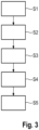
- the system 10 is generally configured to perform a method for performing predictive maintenance of the amplifier module 12 as will be described hereinafter with reference to Figure 3 .
- a first step S1 at least one parameter of the at least one amplifier module 12 is acquired via the measurement data acquisition unit 18.
- the parameter may be acquired by measuring the at least one parameter or rather by receiving the parameter which is transmitted by the amplifier module 12 in case of a changing value of the respective parameter.
- the parameter may be transmitted automatically without any manual input.
- a second step S2 the at least one parameter acquired is analyzed by the measurement data analyzing unit 20 so as to predict the probability and/or time of default of the at least one amplifier module 12 based on the information assigned to the at least one parameter obtained.
- a notification is output in a third step S3 so as to inform the user of the system 10 with regard to the upcoming failure of the amplifier module 12 as well as the remaining time and/or the probability of the upcoming failure.
- a fourth step S4 the failure may be located. This means that a certain component of the complex amplifier module 12 is indicated which probably fails in the near future. The respective location may be output, in particular displayed, so that the user gets informed appropriately.
- a model of the respective amplifier module 12 may be provided wherein the respective components are shown.
- the components may be indicated by different colors according to their status.
- a component that probably fails within the next months may be colored red so that the user knows which component has to be replaced in the near future.
- the system 10 may order automatically a respective spare part for the amplifier module 12 or rather the component thereof that may fail in the near future. This ensures that the respective spare part is on-site once the amplifier module 12 or rather the respective component thereof fails. The downtime of the amplifier module 12 can be reduced significantly.
- the at least one parameter used for predictive maintenance may ensure that the upcoming failure or default of the amplifier module 12 is located.
- the parameter may be assigned to at least one of the operating hours of the amplifier module 12, a temperature of the amplifier module 12 in combination with another parameter of the amplifier module 12, for instance the operating hours of the amplifier module 12, or rather a transistor parameter of the amplifier module 12.
- the transistor parameter may correspond to an input level, a drain current and/or a gate current, in particular wherein the gate current is a common gate current of the amplifier module.
- the amplifier module 12 itself is configured to automatically transmit the respective data related to the parameter.
- the measurement data acquisition unit 18 is configured to measure the respective parameter.
- the measurement data acquisition unit 18 may comprise a sensor for sensing the parameter, namely a temperature sensor, a current sensor and/or a power sensor.
- the measurement data analyzing unit 20 receiving the acquired parameter may compare the parameter acquired with a comparison parameter so as to find a deviation which might indicate an upcoming default.
- the comparison parameter can be a previously acquired value of the same parameter.
- the comparison parameter may correspond to a parameter derived from another amplifier module that may be located at a comparable position.
- the time dependent behavior of the at least one parameter may be taken into account for predicting the probability and/or time of default of the at least one amplifier module 12.
- an increasing gate current may indicate that a failure or rather default of an associated transistor of the amplifier module 12 is probably within the next two to three months.
- an increasing drain current of a transistor of the amplifier module 12 or rather an increasing drain current of the amplifier module 12 may indicate a deterioration or failure of a respective component located downstream of the transistor or rather the amplifier module 12, for instance a (high frequency or rather radio frequency) connection, a cable or a combiner.
- a brazing solder used for the connection may disappear over time in case of high powers processed by the amplifier module 12.
- a high input level namely between the nominal input level and the maximum input level, in combination with a short-term gate current may indicate a high deterioration of a transistor yielding in a failure within the next two to six months.
Landscapes
- Physics & Mathematics (AREA)
- General Physics & Mathematics (AREA)
- Engineering & Computer Science (AREA)
- Power Engineering (AREA)
- General Engineering & Computer Science (AREA)
- Automation & Control Theory (AREA)
- Environmental & Geological Engineering (AREA)
- Amplifiers (AREA)
Claims (13)
- Verfahren zum Durchführen einer vorausschauenden Wartung eines Verstärkermoduls (12), mit den folgenden Schritten:- Erfassen mindestens eines Parameters mindestens eines Verstärkermoduls (12) über eine Messdatenerfassungseinheit (18), und- Analysieren des mindestens einen über eine Messdatenanalyseeinheit (20) erfassten Parameters, wobeidie Ausfallwahrscheinlichkeit und/oder der Ausfallzeitpunkt des mindestens einen Verstärkermoduls (12) unter Berücksichtigung mindestens eines zuvor erfassten Parameters des Verstärkermoduls (12) vorhergesagt wird, so dass eine vorausschauende Wartung für das Verstärkermodul (12) bereitgestellt wird, wobei der mindestens eine Parameter ein Transistorparameter ist, der einem Transistor des Verstärkermoduls (12) direkt zugeordnet ist, wobei der Transistorparameter ein Eingangspegel, ein Drain-Strom und/oder ein Gate-Strom ist,wobei ein Modell und/oder eine Nachschlagetabelle basierend auf gespeicherten empirischen Daten verwendet wird, die unter Berücksichtigung der tatsächlichen Betriebsstunden des Verstärkermoduls (12) die Wahrscheinlichkeit und/oder den Zeitpunkt eines Ausfalls vorhersagt, und wobei eine Benachrichtigung ausgegeben wird, wenn die Analyse einen bevorstehenden Ausfall ergibt, um den Benutzer des Systems (10) über den bevorstehenden Ausfall des Verstärkermoduls (12) sowie die verbleibende Zeit und/oder die Wahrscheinlichkeit des bevorstehenden Ausfalls zu informieren.
- Verfahren nach Anspruch 1, wobei der mindestens eine Parameter einer Temperatur des Verstärkermoduls (12) in Kombination mit einem anderen Parameter des mindestens einen Verstärkermoduls (12) zugeordnet ist, insbesondere wobei der andere Parameter den Betriebsstunden des Verstärkermoduls (12) entspricht.
- Verfahren nach einem der vorstehenden Ansprüche, wobei der Gate-Strom ein gemeinsamer Gate-Strom des Verstärkermoduls (12) ist.
- Verfahren nach einem der vorstehenden Ansprüche, wobei das zeitabhängige Verhalten des mindestens einen Parameters analysiert wird.
- Verfahren nach einem der vorstehenden Ansprüche, wobei der mindestens eine Parameter mit einem Vergleichsparameter gleicher Art verglichen wird, insbesondere wobei der Vergleichsparameter von einem anderen Verstärkermodul erfasst wird und/oder wobei es sich bei dem Vergleichsparameter um einen zuvor erfassten Parameter handelt.
- Verfahren nach einem der vorstehenden Ansprüche, wobei die Benachrichtigung auf einer Anzeige (36) angezeigt wird.
- Verfahren nach Anspruch 1, wobei die Benachrichtigung vom Verstärkermodul (12) selbst, der Messdatenerfassungseinheit (18), der Messdatenanalyseeinheit (20) und/oder einer externen Vorrichtung (28) ausgegeben wird.
- Verfahren nach einem der vorstehenden Ansprüche, wobei der mindestens eine erfasste Parameter und/oder das Analyseergebnis per Telemetrie übertragen wird und/oder wobei auf den mindestens einen erfassten Parameter und/oder das Analyseergebnis über eine Web-Schnittstelle (30) zugegriffen wird.
- System (10) zur vorausschauenden Wartung eines Verstärkermoduls (12), umfassend mindestens eine Messdatenerfassungseinheit (18), mindestens eine Messdatenanalyseeinheit (20) sowie mindestens ein Verstärkermodul (12),wobei die mindestens eine Messdatenerfassungseinheit (18) und die mindestens eine Messdatenanalyseeinheit (20) dazu ausgebildet sind, miteinander zu kommunizieren,wobei die mindestens eine Messdatenerfassungseinheit (18) konfiguriert ist, um mindestens einen Parameter des mindestens einen Verstärkermoduls (12) zu erfassen, undwobei die mindestens eine Messdatenanalyseeinheit (20) konfiguriert ist, um den mindestens einen erfassten Parameter zu empfangen und zu analysieren, wobeidie mindestens eine Messdatenanalyseeinheit (20) konfiguriert ist, um unter Berücksichtigung mindestens eines zuvor erfassten Parameters des Verstärkermoduls (12) die Wahrscheinlichkeit und/oder den Zeitpunkt eines Ausfalls des mindestens einen Verstärkermoduls (12) vorherzusagen, so dass eine vorausschauende Wartung des Verstärkermoduls (12) bereitgestellt wird, wobei der mindestens eine Parameter ein Transistorparameter ist, der einem Transistor des Verstärkermoduls (12) direkt zugeordnet ist, wobei der Transistorparameter ein Eingangspegel, ein Drain-Strom und/oder ein Gate-Strom ist,wobei ein Modell und/oder eine Nachschlagetabelle basierend auf gespeicherten empirischen Daten verwendet wird, die die Wahrscheinlichkeit und/oder den Zeitpunkt eines Ausfalls unter Berücksichtigung der tatsächlichen Betriebsstunden des Verstärkermoduls (12) vorhersagt, und wobei die mindestens eine Messdatenanalyseeinheit (18), die Messdatenerfassungseinheit (20), das Verstärkermodul (12) und/oder eine externe Vorrichtung (28) dazu konfiguriert sind/ist, um eine Benachrichtigung auszugeben, die die vorhergesagte Wahrscheinlichkeit und/oder den Zeitpunkt eines Ausfalls des Verstärkermoduls (12) angibt, wenn die Analyse einen bevorstehenden Ausfall ergibt, um den Benutzer des Systems (10) über den bevorstehenden Ausfall des Verstärkermoduls (12) sowie die verbleibende Zeit und/oder die Wahrscheinlichkeit des bevorstehenden Ausfalls zu informieren.
- System (10) nach Anspruch 9, wobei der mindestens eine Parameter den Betriebsstunden des Verstärkermoduls (12), einem Temperaturwert des Verstärkermoduls (12) in Kombination mit einem anderen Parameter zugeordnet ist und/oder wobei der Gate-Strom ein gemeinsamer Gate-Strom des Verstärkermoduls (12) ist.
- System (10) nach Anspruch 9 oder 10, wobei die mindestens eine Messdatenanalyseeinheit (18) dazu konfiguriert ist, um das zeitabhängige Verhalten des mindestens einen Parameters zu analysieren.
- System (10) nach einem der Ansprüche 9 bis 11, wobei die mindestens eine Messdatenanalyseeinheit (20) dazu konfiguriert ist, um den mindestens einen Parameter mit einem anderen Parameter desselben Typs, der von einem anderen Verstärkermodul (12) erfasst wird, und/oder mit einem zuvor erfassten Parameter zu vergleichen.
- System (10) nach einem der Ansprüche 9 bis 12, wobei die Messdatenerfassungseinheit (18) und die Messdatenanalyseeinheit (20) in eine gemeinsame Vorrichtung (22) integriert sind oder wobei eine Web-Schnittstelle (30) und/oder ein Telemetriesystem (32) bereitgestellt ist/sind, über das/die der mindestens eine erfasste Parameter und/oder das Analyseergebnis übermittelt und/oder abgerufen wird.
Priority Applications (3)
| Application Number | Priority Date | Filing Date | Title |
|---|---|---|---|
| EP18204941.1A EP3650974B1 (de) | 2018-11-07 | 2018-11-07 | Verfahren sowie system zur prädiktiven wartung eines verstärkermoduls |
| US16/675,822 US11519972B2 (en) | 2018-11-07 | 2019-11-06 | Method as well as system for predictive maintenance of an amplifier module |
| CN201911075804.7A CN111157810B (zh) | 2018-11-07 | 2019-11-06 | 用于放大器模块的预测性维护的方法和系统 |
Applications Claiming Priority (1)
| Application Number | Priority Date | Filing Date | Title |
|---|---|---|---|
| EP18204941.1A EP3650974B1 (de) | 2018-11-07 | 2018-11-07 | Verfahren sowie system zur prädiktiven wartung eines verstärkermoduls |
Publications (2)
| Publication Number | Publication Date |
|---|---|
| EP3650974A1 EP3650974A1 (de) | 2020-05-13 |
| EP3650974B1 true EP3650974B1 (de) | 2024-07-17 |
Family
ID=64183975
Family Applications (1)
| Application Number | Title | Priority Date | Filing Date |
|---|---|---|---|
| EP18204941.1A Active EP3650974B1 (de) | 2018-11-07 | 2018-11-07 | Verfahren sowie system zur prädiktiven wartung eines verstärkermoduls |
Country Status (3)
| Country | Link |
|---|---|
| US (1) | US11519972B2 (de) |
| EP (1) | EP3650974B1 (de) |
| CN (1) | CN111157810B (de) |
Families Citing this family (1)
| Publication number | Priority date | Publication date | Assignee | Title |
|---|---|---|---|---|
| US11650646B2 (en) * | 2020-07-30 | 2023-05-16 | Florence Corporation | Systems and methods for providing back-up power to a processor using an un-interruptible power supply |
Family Cites Families (11)
| Publication number | Priority date | Publication date | Assignee | Title |
|---|---|---|---|---|
| JP3402266B2 (ja) * | 1999-06-18 | 2003-05-06 | 日本電気株式会社 | 放送送信機の点検時期予測装置 |
| JP2008076197A (ja) * | 2006-09-20 | 2008-04-03 | Eastman Kodak Co | 試験装置 |
| US9026067B2 (en) * | 2007-04-23 | 2015-05-05 | Dali Systems Co. Ltd. | Remotely reconfigurable power amplifier system and method |
| US8467474B2 (en) * | 2009-09-01 | 2013-06-18 | Ubidyne Inc. | Monitor for spectral degradation of transmitter or receiver |
| CN103217637B (zh) * | 2013-04-02 | 2015-12-23 | 工业和信息化部电子第五研究所 | 热载流子注入失效预警电路 |
| US10444277B2 (en) * | 2014-01-03 | 2019-10-15 | Koninklijke Philips N.V. | Calculation of the probability of gradient coil amplifier failure using environment data |
| US9496831B2 (en) * | 2014-10-17 | 2016-11-15 | Daico Industries, Inc. | Combined high power rf/microwave amplifier with multiple power amplifier units and automatic failure protection |
| US9613947B2 (en) * | 2015-03-20 | 2017-04-04 | Raytheon Company | Monolithic microwave integrated circuit (MMIC) cascode connected transistor circuit |
| US20180062729A1 (en) * | 2016-08-24 | 2018-03-01 | Commscope Technologies Llc | Electronic equipment cabinets having radio frequency relays |
| KR101821173B1 (ko) * | 2017-08-18 | 2018-01-23 | (주)진명아이앤씨 | 오디오 디텍트를 통한 스마트 방송 시스템 |
| CN107918704A (zh) * | 2017-11-08 | 2018-04-17 | 中国电子产品可靠性与环境试验研究所 | 电荷放大器贮存寿命预测方法、装置、存储介质和计算机设备 |
-
2018
- 2018-11-07 EP EP18204941.1A patent/EP3650974B1/de active Active
-
2019
- 2019-11-06 CN CN201911075804.7A patent/CN111157810B/zh active Active
- 2019-11-06 US US16/675,822 patent/US11519972B2/en active Active
Also Published As
| Publication number | Publication date |
|---|---|
| CN111157810A (zh) | 2020-05-15 |
| EP3650974A1 (de) | 2020-05-13 |
| US11519972B2 (en) | 2022-12-06 |
| US20200141992A1 (en) | 2020-05-07 |
| CN111157810B (zh) | 2025-04-25 |
Similar Documents
| Publication | Publication Date | Title |
|---|---|---|
| US11550000B2 (en) | Smart grid distribution transformer | |
| US10551243B2 (en) | Power efficient machine diagnostic monitoring using multiple vibration sensor wireless configuration | |
| US6621413B1 (en) | Wireless monitoring of a mobile magnet | |
| US9746524B2 (en) | System and method for monitoring battery status | |
| RU2608242C1 (ru) | Переносное устройство для полевого технического обслуживания с улучшенной диагностикой | |
| US10372088B2 (en) | Power consumption management device, power consumption management system, power consumption management method, and power consumption management program | |
| US20070257807A1 (en) | Circuit protector monitoring assembly | |
| WO2015166349A1 (en) | Trending machine health data using rfid transponders | |
| US10488528B2 (en) | System and methods for commissioning and maintaining industrial equipment | |
| KR101050747B1 (ko) | 서버 장치 및 프로그램 | |
| EP3650974B1 (de) | Verfahren sowie system zur prädiktiven wartung eines verstärkermoduls | |
| Benitez et al. | Sensors calibration for Metrology 4.0 | |
| EP1946419B1 (de) | System zum steuern, schützen und überwachen des status von zwangskühlmotoren für stromtransformatoren und ähnliches | |
| EP3457242B1 (de) | Verfahren zur automatischen benachrichtigung einer beabsichtigten person sowie test- und messvorrichtung | |
| US20090082657A1 (en) | Intelligent helium compressor | |
| KR101707964B1 (ko) | 배전반 시스템 | |
| US20050177347A1 (en) | Manufacturing device with automatic remote monitoring and a corresponding monitoring method | |
| US20230400838A1 (en) | Apparatuses and methods for non-disruptive replacement of simplex i/o components | |
| JP2025033239A (ja) | 制御装置、制御方法、および制御プログラム | |
| JP2009509370A (ja) | 機械ないし設備とサービスユニットとの間のデータ伝送のためのシステム | |
| WO2019207457A1 (en) | Method for monitoring and controlling motors and a system thereof | |
| US20160223237A1 (en) | User interface for predictive failure analysis of a cooling device | |
| JP2018121167A (ja) | 電力監視制御システムおよび電力監視制御システム用プログラム | |
| KR101578557B1 (ko) | 계전기 감시 장치 | |
| JP2018146517A (ja) | 電子秤及び店舗管理システム |
Legal Events
| Date | Code | Title | Description |
|---|---|---|---|
| PUAI | Public reference made under article 153(3) epc to a published international application that has entered the european phase |
Free format text: ORIGINAL CODE: 0009012 |
|
| STAA | Information on the status of an ep patent application or granted ep patent |
Free format text: STATUS: THE APPLICATION HAS BEEN PUBLISHED |
|
| AK | Designated contracting states |
Kind code of ref document: A1 Designated state(s): AL AT BE BG CH CY CZ DE DK EE ES FI FR GB GR HR HU IE IS IT LI LT LU LV MC MK MT NL NO PL PT RO RS SE SI SK SM TR |
|
| AX | Request for extension of the european patent |
Extension state: BA ME |
|
| STAA | Information on the status of an ep patent application or granted ep patent |
Free format text: STATUS: REQUEST FOR EXAMINATION WAS MADE |
|
| 17P | Request for examination filed |
Effective date: 20201021 |
|
| RBV | Designated contracting states (corrected) |
Designated state(s): AL AT BE BG CH CY CZ DE DK EE ES FI FR GB GR HR HU IE IS IT LI LT LU LV MC MK MT NL NO PL PT RO RS SE SI SK SM TR |
|
| STAA | Information on the status of an ep patent application or granted ep patent |
Free format text: STATUS: EXAMINATION IS IN PROGRESS |
|
| P01 | Opt-out of the competence of the unified patent court (upc) registered |
Effective date: 20230525 |
|
| 17Q | First examination report despatched |
Effective date: 20230613 |
|
| GRAP | Despatch of communication of intention to grant a patent |
Free format text: ORIGINAL CODE: EPIDOSNIGR1 |
|
| STAA | Information on the status of an ep patent application or granted ep patent |
Free format text: STATUS: GRANT OF PATENT IS INTENDED |
|
| INTG | Intention to grant announced |
Effective date: 20240209 |
|
| GRAS | Grant fee paid |
Free format text: ORIGINAL CODE: EPIDOSNIGR3 |
|
| GRAA | (expected) grant |
Free format text: ORIGINAL CODE: 0009210 |
|
| STAA | Information on the status of an ep patent application or granted ep patent |
Free format text: STATUS: THE PATENT HAS BEEN GRANTED |
|
| AK | Designated contracting states |
Kind code of ref document: B1 Designated state(s): AL AT BE BG CY CZ DE DK EE ES FI FR GB GR HR HU IS IT LT LU LV MC MK MT NL NO PL PT RO RS SE SI SK SM TR |
|
| RBV | Designated contracting states (corrected) |
Designated state(s): AL AT BE BG CY CZ DE DK EE ES FI FR GB GR HR HU IS IT LT LU LV MC MK MT NL NO PL PT RO RS SE SI SK SM TR |
|
| REG | Reference to a national code |
Ref country code: DE Ref legal event code: R096 Ref document number: 602018071805 Country of ref document: DE |
|
| REG | Reference to a national code |
Ref country code: LT Ref legal event code: MG9D |
|
| REG | Reference to a national code |
Ref country code: NL Ref legal event code: MP Effective date: 20240717 |
|
| PG25 | Lapsed in a contracting state [announced via postgrant information from national office to epo] |
Ref country code: PT Free format text: LAPSE BECAUSE OF FAILURE TO SUBMIT A TRANSLATION OF THE DESCRIPTION OR TO PAY THE FEE WITHIN THE PRESCRIBED TIME-LIMIT Effective date: 20241118 |
|
| REG | Reference to a national code |
Ref country code: AT Ref legal event code: MK05 Ref document number: 1704730 Country of ref document: AT Kind code of ref document: T Effective date: 20240717 |
|
| PG25 | Lapsed in a contracting state [announced via postgrant information from national office to epo] |
Ref country code: NL Free format text: LAPSE BECAUSE OF FAILURE TO SUBMIT A TRANSLATION OF THE DESCRIPTION OR TO PAY THE FEE WITHIN THE PRESCRIBED TIME-LIMIT Effective date: 20240717 |
|
| PG25 | Lapsed in a contracting state [announced via postgrant information from national office to epo] |
Ref country code: PT Free format text: LAPSE BECAUSE OF FAILURE TO SUBMIT A TRANSLATION OF THE DESCRIPTION OR TO PAY THE FEE WITHIN THE PRESCRIBED TIME-LIMIT Effective date: 20241118 Ref country code: NL Free format text: LAPSE BECAUSE OF FAILURE TO SUBMIT A TRANSLATION OF THE DESCRIPTION OR TO PAY THE FEE WITHIN THE PRESCRIBED TIME-LIMIT Effective date: 20240717 |
|
| PG25 | Lapsed in a contracting state [announced via postgrant information from national office to epo] |
Ref country code: NO Free format text: LAPSE BECAUSE OF FAILURE TO SUBMIT A TRANSLATION OF THE DESCRIPTION OR TO PAY THE FEE WITHIN THE PRESCRIBED TIME-LIMIT Effective date: 20241017 |
|
| PG25 | Lapsed in a contracting state [announced via postgrant information from national office to epo] |
Ref country code: GR Free format text: LAPSE BECAUSE OF FAILURE TO SUBMIT A TRANSLATION OF THE DESCRIPTION OR TO PAY THE FEE WITHIN THE PRESCRIBED TIME-LIMIT Effective date: 20241018 Ref country code: FI Free format text: LAPSE BECAUSE OF FAILURE TO SUBMIT A TRANSLATION OF THE DESCRIPTION OR TO PAY THE FEE WITHIN THE PRESCRIBED TIME-LIMIT Effective date: 20240717 Ref country code: PL Free format text: LAPSE BECAUSE OF FAILURE TO SUBMIT A TRANSLATION OF THE DESCRIPTION OR TO PAY THE FEE WITHIN THE PRESCRIBED TIME-LIMIT Effective date: 20240717 |
|
| PG25 | Lapsed in a contracting state [announced via postgrant information from national office to epo] |
Ref country code: BG Free format text: LAPSE BECAUSE OF FAILURE TO SUBMIT A TRANSLATION OF THE DESCRIPTION OR TO PAY THE FEE WITHIN THE PRESCRIBED TIME-LIMIT Effective date: 20240717 |
|
| PG25 | Lapsed in a contracting state [announced via postgrant information from national office to epo] |
Ref country code: LV Free format text: LAPSE BECAUSE OF FAILURE TO SUBMIT A TRANSLATION OF THE DESCRIPTION OR TO PAY THE FEE WITHIN THE PRESCRIBED TIME-LIMIT Effective date: 20240717 |
|
| PG25 | Lapsed in a contracting state [announced via postgrant information from national office to epo] |
Ref country code: IS Free format text: LAPSE BECAUSE OF FAILURE TO SUBMIT A TRANSLATION OF THE DESCRIPTION OR TO PAY THE FEE WITHIN THE PRESCRIBED TIME-LIMIT Effective date: 20241117 Ref country code: AT Free format text: LAPSE BECAUSE OF FAILURE TO SUBMIT A TRANSLATION OF THE DESCRIPTION OR TO PAY THE FEE WITHIN THE PRESCRIBED TIME-LIMIT Effective date: 20240717 |
|
| PG25 | Lapsed in a contracting state [announced via postgrant information from national office to epo] |
Ref country code: HR Free format text: LAPSE BECAUSE OF FAILURE TO SUBMIT A TRANSLATION OF THE DESCRIPTION OR TO PAY THE FEE WITHIN THE PRESCRIBED TIME-LIMIT Effective date: 20240717 |
|
| PG25 | Lapsed in a contracting state [announced via postgrant information from national office to epo] |
Ref country code: RS Free format text: LAPSE BECAUSE OF FAILURE TO SUBMIT A TRANSLATION OF THE DESCRIPTION OR TO PAY THE FEE WITHIN THE PRESCRIBED TIME-LIMIT Effective date: 20241017 Ref country code: ES Free format text: LAPSE BECAUSE OF FAILURE TO SUBMIT A TRANSLATION OF THE DESCRIPTION OR TO PAY THE FEE WITHIN THE PRESCRIBED TIME-LIMIT Effective date: 20240717 |
|
| PG25 | Lapsed in a contracting state [announced via postgrant information from national office to epo] |
Ref country code: RS Free format text: LAPSE BECAUSE OF FAILURE TO SUBMIT A TRANSLATION OF THE DESCRIPTION OR TO PAY THE FEE WITHIN THE PRESCRIBED TIME-LIMIT Effective date: 20241017 Ref country code: PL Free format text: LAPSE BECAUSE OF FAILURE TO SUBMIT A TRANSLATION OF THE DESCRIPTION OR TO PAY THE FEE WITHIN THE PRESCRIBED TIME-LIMIT Effective date: 20240717 Ref country code: NO Free format text: LAPSE BECAUSE OF FAILURE TO SUBMIT A TRANSLATION OF THE DESCRIPTION OR TO PAY THE FEE WITHIN THE PRESCRIBED TIME-LIMIT Effective date: 20241017 Ref country code: LV Free format text: LAPSE BECAUSE OF FAILURE TO SUBMIT A TRANSLATION OF THE DESCRIPTION OR TO PAY THE FEE WITHIN THE PRESCRIBED TIME-LIMIT Effective date: 20240717 Ref country code: IS Free format text: LAPSE BECAUSE OF FAILURE TO SUBMIT A TRANSLATION OF THE DESCRIPTION OR TO PAY THE FEE WITHIN THE PRESCRIBED TIME-LIMIT Effective date: 20241117 Ref country code: HR Free format text: LAPSE BECAUSE OF FAILURE TO SUBMIT A TRANSLATION OF THE DESCRIPTION OR TO PAY THE FEE WITHIN THE PRESCRIBED TIME-LIMIT Effective date: 20240717 Ref country code: GR Free format text: LAPSE BECAUSE OF FAILURE TO SUBMIT A TRANSLATION OF THE DESCRIPTION OR TO PAY THE FEE WITHIN THE PRESCRIBED TIME-LIMIT Effective date: 20241018 Ref country code: FI Free format text: LAPSE BECAUSE OF FAILURE TO SUBMIT A TRANSLATION OF THE DESCRIPTION OR TO PAY THE FEE WITHIN THE PRESCRIBED TIME-LIMIT Effective date: 20240717 Ref country code: ES Free format text: LAPSE BECAUSE OF FAILURE TO SUBMIT A TRANSLATION OF THE DESCRIPTION OR TO PAY THE FEE WITHIN THE PRESCRIBED TIME-LIMIT Effective date: 20240717 Ref country code: BG Free format text: LAPSE BECAUSE OF FAILURE TO SUBMIT A TRANSLATION OF THE DESCRIPTION OR TO PAY THE FEE WITHIN THE PRESCRIBED TIME-LIMIT Effective date: 20240717 Ref country code: AT Free format text: LAPSE BECAUSE OF FAILURE TO SUBMIT A TRANSLATION OF THE DESCRIPTION OR TO PAY THE FEE WITHIN THE PRESCRIBED TIME-LIMIT Effective date: 20240717 |
|
| PG25 | Lapsed in a contracting state [announced via postgrant information from national office to epo] |
Ref country code: DK Free format text: LAPSE BECAUSE OF FAILURE TO SUBMIT A TRANSLATION OF THE DESCRIPTION OR TO PAY THE FEE WITHIN THE PRESCRIBED TIME-LIMIT Effective date: 20240717 Ref country code: SM Free format text: LAPSE BECAUSE OF FAILURE TO SUBMIT A TRANSLATION OF THE DESCRIPTION OR TO PAY THE FEE WITHIN THE PRESCRIBED TIME-LIMIT Effective date: 20240717 Ref country code: RO Free format text: LAPSE BECAUSE OF FAILURE TO SUBMIT A TRANSLATION OF THE DESCRIPTION OR TO PAY THE FEE WITHIN THE PRESCRIBED TIME-LIMIT Effective date: 20240717 |
|
| REG | Reference to a national code |
Ref country code: DE Ref legal event code: R097 Ref document number: 602018071805 Country of ref document: DE |
|
| PG25 | Lapsed in a contracting state [announced via postgrant information from national office to epo] |
Ref country code: EE Free format text: LAPSE BECAUSE OF FAILURE TO SUBMIT A TRANSLATION OF THE DESCRIPTION OR TO PAY THE FEE WITHIN THE PRESCRIBED TIME-LIMIT Effective date: 20240717 |
|
| PG25 | Lapsed in a contracting state [announced via postgrant information from national office to epo] |
Ref country code: CZ Free format text: LAPSE BECAUSE OF FAILURE TO SUBMIT A TRANSLATION OF THE DESCRIPTION OR TO PAY THE FEE WITHIN THE PRESCRIBED TIME-LIMIT Effective date: 20240717 |
|
| PG25 | Lapsed in a contracting state [announced via postgrant information from national office to epo] |
Ref country code: SK Free format text: LAPSE BECAUSE OF FAILURE TO SUBMIT A TRANSLATION OF THE DESCRIPTION OR TO PAY THE FEE WITHIN THE PRESCRIBED TIME-LIMIT Effective date: 20240717 |
|
| PLBE | No opposition filed within time limit |
Free format text: ORIGINAL CODE: 0009261 |
|
| STAA | Information on the status of an ep patent application or granted ep patent |
Free format text: STATUS: NO OPPOSITION FILED WITHIN TIME LIMIT |
|
| 26N | No opposition filed |
Effective date: 20250422 |
|
| PG25 | Lapsed in a contracting state [announced via postgrant information from national office to epo] |
Ref country code: MC Free format text: LAPSE BECAUSE OF FAILURE TO SUBMIT A TRANSLATION OF THE DESCRIPTION OR TO PAY THE FEE WITHIN THE PRESCRIBED TIME-LIMIT Effective date: 20240717 |
|
| PG25 | Lapsed in a contracting state [announced via postgrant information from national office to epo] |
Ref country code: LU Free format text: LAPSE BECAUSE OF NON-PAYMENT OF DUE FEES Effective date: 20241107 |
|
| REG | Reference to a national code |
Ref country code: BE Ref legal event code: MM Effective date: 20241130 |
|
| PG25 | Lapsed in a contracting state [announced via postgrant information from national office to epo] |
Ref country code: SE Free format text: LAPSE BECAUSE OF FAILURE TO SUBMIT A TRANSLATION OF THE DESCRIPTION OR TO PAY THE FEE WITHIN THE PRESCRIBED TIME-LIMIT Effective date: 20240717 |
|
| PG25 | Lapsed in a contracting state [announced via postgrant information from national office to epo] |
Ref country code: BE Free format text: LAPSE BECAUSE OF NON-PAYMENT OF DUE FEES Effective date: 20241130 |
|
| PGFP | Annual fee paid to national office [announced via postgrant information from national office to epo] |
Ref country code: DE Payment date: 20251118 Year of fee payment: 8 |
|
| PGFP | Annual fee paid to national office [announced via postgrant information from national office to epo] |
Ref country code: GB Payment date: 20251120 Year of fee payment: 8 |
|
| PGFP | Annual fee paid to national office [announced via postgrant information from national office to epo] |
Ref country code: FR Payment date: 20251120 Year of fee payment: 8 |
|
| PG25 | Lapsed in a contracting state [announced via postgrant information from national office to epo] |
Ref country code: IT Free format text: LAPSE BECAUSE OF FAILURE TO SUBMIT A TRANSLATION OF THE DESCRIPTION OR TO PAY THE FEE WITHIN THE PRESCRIBED TIME-LIMIT Effective date: 20240717 |
|
| PG25 | Lapsed in a contracting state [announced via postgrant information from national office to epo] |
Ref country code: HU Free format text: LAPSE BECAUSE OF FAILURE TO SUBMIT A TRANSLATION OF THE DESCRIPTION OR TO PAY THE FEE WITHIN THE PRESCRIBED TIME-LIMIT; INVALID AB INITIO Effective date: 20181107 |
|
| PG25 | Lapsed in a contracting state [announced via postgrant information from national office to epo] |
Ref country code: CY Free format text: LAPSE BECAUSE OF FAILURE TO SUBMIT A TRANSLATION OF THE DESCRIPTION OR TO PAY THE FEE WITHIN THE PRESCRIBED TIME-LIMIT; INVALID AB INITIO Effective date: 20181107 |