EP3651003B1 - Dispositif, écran et procédé d'entrée tactile - Google Patents
Dispositif, écran et procédé d'entrée tactile Download PDFInfo
- Publication number
- EP3651003B1 EP3651003B1 EP18204793.6A EP18204793A EP3651003B1 EP 3651003 B1 EP3651003 B1 EP 3651003B1 EP 18204793 A EP18204793 A EP 18204793A EP 3651003 B1 EP3651003 B1 EP 3651003B1
- Authority
- EP
- European Patent Office
- Prior art keywords
- light
- touch
- frame
- input device
- sensitive input
- Prior art date
- Legal status (The legal status is an assumption and is not a legal conclusion. Google has not performed a legal analysis and makes no representation as to the accuracy of the status listed.)
- Active
Links
Images


Classifications
-
- G—PHYSICS
- G06—COMPUTING OR CALCULATING; COUNTING
- G06F—ELECTRIC DIGITAL DATA PROCESSING
- G06F3/00—Input arrangements for transferring data to be processed into a form capable of being handled by the computer; Output arrangements for transferring data from processing unit to output unit, e.g. interface arrangements
- G06F3/01—Input arrangements or combined input and output arrangements for interaction between user and computer
- G06F3/03—Arrangements for converting the position or the displacement of a member into a coded form
- G06F3/041—Digitisers, e.g. for touch screens or touch pads, characterised by the transducing means
- G06F3/042—Digitisers, e.g. for touch screens or touch pads, characterised by the transducing means by opto-electronic means
- G06F3/0421—Digitisers, e.g. for touch screens or touch pads, characterised by the transducing means by opto-electronic means by interrupting or reflecting a light beam, e.g. optical touch-screen
-
- G—PHYSICS
- G06—COMPUTING OR CALCULATING; COUNTING
- G06F—ELECTRIC DIGITAL DATA PROCESSING
- G06F3/00—Input arrangements for transferring data to be processed into a form capable of being handled by the computer; Output arrangements for transferring data from processing unit to output unit, e.g. interface arrangements
- G06F3/01—Input arrangements or combined input and output arrangements for interaction between user and computer
- G06F3/03—Arrangements for converting the position or the displacement of a member into a coded form
- G06F3/041—Digitisers, e.g. for touch screens or touch pads, characterised by the transducing means
- G06F3/0416—Control or interface arrangements specially adapted for digitisers
- G06F3/0418—Control or interface arrangements specially adapted for digitisers for error correction or compensation, e.g. based on parallax, calibration or alignment
Definitions
- the invention relates to a touch-sensitive input device for a screen. Further, the invention relates to a respective screen and to a respective method.
- Digital signage products such as interactive white boards are increasingly used in schools, meeting rooms, airports etc. They are used for education, presentations or business information display.
- Such digital signage displays may comprise a controller that allows user interaction with the display.
- controllers may e.g. be provided in a dedicated computer or may be integrated into the digital signage display.
- Digital signage products usually comprise a touch sensor for easily detecting user input, e.g. with the finger, without the user being required to use any dedicated input devices.
- touch sensing technology for large screens uses IR (InfraRed) technology.
- IR InfraRed
- Such IR based input devices are cheap and the installation may easily be performed on any flat display surface.
- IR-based touch sensors can be easily produced for and be used with displays of almost every size.
- IR-based touch devices usually comprise a series of transmitters and a corresponding series of receivers which are linearly arranged on the two opposite edges of the display.
- the transmitters emit IR rays or light and the receivers receive the emitted rays or light, as long as no object obstructs the path of the rays. If an object is located between the transmitter and the receiver, e.g. a finger of a user, it will block the rays. Consequently, the receivers will not receive the rays from the transmitters and an attached processing unit of the touch system may determine the position of the object by analyzing which receivers still receive the emitted IR light or not. Therefore, when a user touches the screen or display, the user blocks the respective IR ray(s) and the system may identify the respective position on the screen or display.
- the surface of the respective display may not be flat because of production process fails or mounting problems.
- the display may comprise a power supply, backlight units and the like. These elements may heat up the display.
- the environment may further heat up the display e.g. depending on the ambient temperature and incident sunlight. Therefore, the surface may have indentations or elevations that may e.g. be caused by the heat and the respective thermal stress.
- the non-flat or curved surface may change the direction of emission of the transmitters or the direction of reception of the receivers, e.g. if the edges of the display are elevated or lowered and therefore twisting the frame of the display.
- the result may be a change of the ray direction. This means that some receivers may not receive the rays and the system may suppose that an object may block the rays. Therefore, touch events may not be detected or false touch events may be detected.
- Document US 2017 / 025 097 A1 discloses a control device that allows positioning sending and receiving elements of a 3D mid-air input device.
- Document US 6 421 042 B1 discloses a coordinate-position inputting device with a light emitting device and at least two pickup devices.
- Document CN 101 963 867 B discloses an input device.
- Document DE 10 2004 005501 A1 discloses an input device with mechanical input elements.
- Document DE 199 62 552 A1 discloses a touch-screen with input element, wherein at least one input element is vertically movable.
- Document US 2005 / 057 528 A1 discloses a screen with a touch sensitive user interface for command input via local touching of the user interface and with electrical means for generating a haptically perceptible signal.
- Document EP 2 824 548 A1 discloses a coordinate detecting device for a display surface with two optical sensors including light emitting and receiving devices.
- Document US 2001 / 022 579 A1 discloses an apparatus for inputting coordinates with an optical unit that comprises a light source and a light receiver.
- Document US 2002 / 033 805 A1 discloses an electronic blackboard that optically detects input information on a display surface by optically determining the corresponding coordinates.
- the present invention is based on the finding that elevated or lowered edges or corners or spots on the surface of the screen may pose problems when using the touch screen device. It is understood, that the terms screen or display may be used interchangeably with regard to the present invention.
- the present invention discloses the touch-sensitive input device that may automatically correct elevated or lowered corners of its frame.
- the frame will be mounted on a screen or display device.
- the frame may for example be mounted on the housing of a frame of a whiteboard with a projector projecting images onto the whiteboard from the front or the back (with translucent whiteboards).
- the frame may be mounted around an active display, like e.g. an LCD display or an OLED display or any other type of display.
- the frame carries the light emitters. It is understood, that any adequate number of light emitters may be provided, depending on the respective application. The number of light emitters will usually mainly depend on the required resolution of the touch-sensitive input device and the size of the display or screen on which the touch-sensitive input device is mounted. The same applies to the light receivers, which may also be called light sensors, which are also mounted on the frame on an edge opposite to the edge on which the light emitters are mounted. It is understood, that the light emitters and the light receivers may operate in the infrared light spectrum. It is also understood, that any other light spectrum may also be used.
- the light emitters and the light receivers may be provided only on one first edge and the opposing second edge or on two neighboring first edges and two neighboring second edges.
- touch events may be detected only on one axis.
- two sets of light beams will be emitted by the light emitters that will be orthogonal to each other and touch events may be detected in a two-dimensional coordinate system.
- Such an arrangement may also be called a matrix like arrangement with light beams being emitted in X direction and light beams being emitted in Y direction.
- the touch-sensitive input device will determine if a touch event happened based on the light emitted by the light emitters and based on which ones of the light receivers that receive the emitted light.
- markers may be shown on the screen or display and a user may be required to provide an input on the shown markers. This allows aligning the coordinate system of the screen or display with the coordinate system of the touch-sensitive input device.
- the touch-sensitive input device therefore provides the calibration processor that is provided for mechanically calibrating the touch-sensitive input device with regard to the surface of the screen or display.
- the calibration processor according to the present invention therefore not necessarily performs any calibration of the coordinate system of the touch-sensitive input device with regard to the coordinate system of the screen or display.
- the calibration processor may also perform such additional calibrations, e.g. after mechanically calibrating the touch-sensitive input device.
- At least one electric actuator is provided on at least one edge or corner of the frame.
- the electric actuators are mechanically arranged to elevate or lower the respective edge of the frame. It is understood, that any adequate mechanical arrangement may be provided, such an arrangement may e.g. comprise guides, slides, and/or gears and the like. In any case, the electric actuators may be controlled by the calibration processor as required.
- the calibration processor may therefore elevate or lower edges and/or corners of the frame as required. In a calibration mode the calibration processor may therefore control the light emitters to emit light and may verify which of the light receivers receives the emitted light. It is understood, that the mechanical calibration should be performed without any user touching the surface of the screen or display. This fact may be noted in the instructions of the touch-sensitive input device. As alternative or in addition, a respective note may be provided to the user via the screen or display.
- every light receiver should receive the emitted light from the light emitters. If in the calibration mode a light receiver does not receive the emitted light as expected, a mechanical distortion of the frame may be present. Such a distortion may e.g. lead to a light emitter emitting the light into the surface of the screen or away from the surface of the screen instead of parallel to the screen's surface.
- the calibration processor may therefore determine, if a mechanical distortion of the frame of the touch-sensitive input device is present and where the mechanical distortion is present.
- the calibration processor may then control the respective electric actuators accordingly to compensate the mechanical distortion. After compensating the mechanical distortion, the light receivers and the respective light emitters will be aligned to each other and touch events may be reliably detected.
- the light emitters may each be configured to emit a focused and directed beam to a respective one of the light receivers
- the calibration processor may be configured to control in the calibration mode all light emitters to emit light concurrently and to evaluate the output signals of the light receivers concurrently to determine, which of the light receivers receives the emitted light.
- the light emitters may e.g. comprise infrared laser diodes or infrared LEDs (light emitting diodes) with lenses that focus the emitted light onto a respective one of the light receivers.
- a single light emitter will provide a single light receiver with an input signal, i.e. the emitted light.
- the resolution of the touch-sensitive input device for detecting touch events will depend on the number of light emitters and light receivers. This numbers may be adapted according to the respective application's requirements.
- all light emitters may emit light at the same time and all light receivers may be evaluated at the same time.
- the calibration processor may for example comprise a control interface that couples the calibration processor with every one of the light emitters.
- a control interface may be a parallel interface that has a direct connection to every one of the light emitters.
- a control interface may also comprise a serial interface that e.g. provides the respective control data to a controller of the light emitters. In this case, the controller of the light emitters will receive the serial control signals and control the individual light emitters accordingly.
- the coupling between the calibration processor and the light receivers may in analogy also comprise a parallel interface or a serial interface.
- every light receiver may be individually coupled to the calibration processor.
- a controller may be provided for the light receivers. Such a controller may be coupled to the calibration processor via a serial interface, while each one of the light emitters is individually coupled to the controller.
- the light emitters may each be configured to emit an unfocused beam in the direction of the light receivers
- the calibration processor may be configured to control in the calibration mode the light emitters to emit light sequentially and to evaluate the output signals of the light receivers to determine, which of the light receivers receives the emitted light.
- the light emitters may emit directed but unfocused light. Therefore, the light emitted by a single light emitter may be received by a plurality of light receivers. In order to detect touch events all over the screen, it is therefore necessary to cyclically activate single light emitters and evaluate the light receivers.
- the interface to the light emitters and light receivers is simplified, since the calibration controller requires only a single interface to the light emitters. A simple multi-path switch may then be provided to contact the respective light emitters.
- the light receivers may also be evaluated sequentially, in this case the interface to the light receivers may also be simplified accordingly.
- the calibration processor may assume that a mechanical misalignment of the touch-sensitive input device or an elevation of the screen may be present in the path between the light receivers that did not receive light and the respective light emitters.
- the calibration processor may comprise a mapping table, e.g. stored in a memory of the calibration processor, that comprises position information about the light emitters and the light receivers with regard to the frame and therefore allows mapping the single light emitters and light receivers to a position on the frame, wherein the calibration processor may be configured to determine the control of the electric actuators based on the position of the light receivers that do not receive the emitted light.
- a mapping table e.g. stored in a memory of the calibration processor, that comprises position information about the light emitters and the light receivers with regard to the frame and therefore allows mapping the single light emitters and light receivers to a position on the frame
- the calibration processor may be configured to determine the control of the electric actuators based on the position of the light receivers that do not receive the emitted light.
- the calibration processor may assume that some form of mechanical calibration is required.
- the mapping table allows the calibration processor to determine where on the frame the light receivers that do not receive the emitted light are located. Since the frame is positioned around the screen, this also allows the calibration processor to determine where on the screen the light is blocked.
- the touch-sensitive input device may comprise one of the electric actuators on every corner of the frame.
- every one of the electric actuators may be individually controlled, every corner of the frame may be individually lowered or elevated by the calibration processor.
- the calibration processor may be configured to control all electric actuators to elevate the respective corner of the frame, if groups of a limited number of light receivers which are arranged next to each other do not receive the respective emitted light, i.e. if the light receivers that do not receive the emitted light indicate a local touch event.
- a limited number of light receivers that are arranged next to each other do not receive light from the respective light emitter during normal operation when a touch event is provided on the screen's surface.
- the limited number may e.g. refer to a single light receiver or a predefined number, like e.g. two or three or four or more light emitting receivers. It is understood, that the limited number may be defined based on the spatial resolution of the touch-sensitive input device and the area that should be accepted as a single touch event, like e.g. the area occupied by a fingertip or by a pen or stylus or the like.
- Touch events may therefore be referred to as local touch events if the area (size) of the touch event is limited and a position for the touch event may be determined, like e.g. when a finger touches the screen.
- the calibration processor may assume that the surface of the screen is locally elevated.
- the calibration processor may be configured to control the electric actuators to elevate the respective corner of the frame.
- a distortion of the screen may e.g. be present, when a single corner of the screen is elevated or lowered with respect to the other corners of the screen or when two neighboring or opposite corners are elevated or lowered with respect to the remaining corners.
- the line that blocks the light beams may be inclined with regard to the edges of the frame. This means that the emitted light of light emitters on two of the edges will be blocked.
- the calibration controller may simply elevate or lower the respective corner. If the light of neighboring light emitters on a single edge is blocked, the calibration controller may elevate or lower the respective edge, e.g. by controlling the electric actuators on both ends of the respective edge.
- the calibration processor when controlling the electric actuators may be configured to control the respective ones of the electric actuators to maximally lower to a predetermined minimum position and in continuation to maximally elevate to a predetermined maximum position until all light receivers receive the respective emitted light or vice versa.
- the calibration processor may e.g. continuously monitor the light receivers and stop moving the electric actuators when all light receivers receive the respective emitted light.
- the calibration processor may start lowering the respective corners or moving the corners down, i.e. toward the surface of the screen. If a minimum point or position is reached and the light path is still blocked, the calibration processor may move the respective corners up, i.e. away from the surface of the screen. It is understood that the configuration processor may also start the calibration by elevating the respective corners.
- the minimum position will usually be defined by the frame of the touch-sensitive input device touching the surface of the screen.
- the maximum position may be defined as required. Usually, the larger the screen is, the higher the maximum position will be.
- the maximum position may e.g. range between some millimeters and 10s of centimeters, like e.g. 10 mm, 20 mm, 10 cm, 20 cm or the like.
- the calibration processor may e.g. comprise a general-purpose processor that may be coupled to a memory and execute a respective program stored in the memory.
- the general-purpose processor may be coupled to the interfaces that couples the calibration processor with the light emitters and the light receivers to perform the required calibration functions.
- the function of the calibration processor may also be provided in a central controller of the touch-sensitive input device, e.g. the controller that evaluates the signals from the light receivers during normal operation of the touch-sensitive input device.
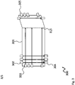
- Fig. 1 shows a block diagram of a touch-sensitive input device 100.
- the touch-sensitive input device 100 comprises a frame 101.
- the frame 101 carries a number of light emitters 102, 103 arranged on the top and the left edges of the frame 101. Further, the frame 101 carries a number of light receivers 104, 105 arranged on the right and the bottom edges of the frame 101. It is understood, that for sake of clarity only one of the light emitters 102, 103 and only one of the light receivers 104, 105 is provided with a reference sign on each one of the edges.
- the touch-sensitive input device 100 further comprises four electric actuators 108, 109, 110, 111 arranged at the four corners of the frame 101.
- a calibration processor 112 is provided that is coupled to the light emitters 102, 103, the light receivers 104, 105, and the electric actuators 108, 109, 110,111.
- the light emitters 102, 103 may be controlled by the calibration processor 112 to emit infrared light to a respective one of the light receivers 104, 105.
- the calibration processor 112 may further evaluate the output signals of the light receivers 104, 105, and control the electric actuators 108, 109, 110, 111.
- the electric actuators 108, 109, 110, 111 are each arranged to elevate or lower the respective edge of the frame 101. This means that by controlling the electric actuators 108, 109, 110, 111, the calibration processor 112 may deform the frame 101 or correct a distortion of the frame 101.
- the calibration processor 112 may therefore control the light emitters 102, 103 to emit light.
- the light emitters 102, 103 may emit a focused directed beam to the respective light receivers 104, 105. Therefore, all light emitters 102, 103 may be activated at the same time. It is understood, that a sequential activation of the light emitters 102, 103 is also possible if the light emitters 102, 103 emitters an unfocused beam that may be received by multiple light receivers 104, 105.
- the calibration processor 112 may then evaluate the output signals of the light receivers 104, 105 to determine if all light receivers 104, 105 receive the respective emitted light. If this is the case, i.e. all light receivers 104,105 receive light as expected, no further calibration is required and the calibration may be finished.
- the calibration processor 112 may perform a calibration of the touch-sensitive input device 100. It is understood, that a calibration of the touch-sensitive input device 100 in this context refers to a mechanical calibration of the touch-sensitive input device 100.
- the calibration processor 112 comprises a mapping table 113 that comprises position information about the light emitters 102,103 and the light receivers 104, 105 with regard to the frame 101.
- the mapping table 113 may e.g. comprise for every one of the light emitters 102, 103 the information on which one of the edges the respective light emitter 102, 103 is arranged on and the number of the light emitter 102, 103 in the sequence of light emitters 102, 103.
- the position information may e.g. indicate that the light emitter 102 is the first light emitter on the upper edge of the frame 101 starting from the left, and that the light receiver 104 is the first light receiver on the lower edge of the frame 101 starting from the left.
- the calibration processor 112 may determine if the screen 150 is deformed and e.g. comprises an elevation, or if the frame 101 is deformed or distorted. This will be explained in more detail with regard to Figs. 2 - 4 below.
- the calibration processor 112 will then determine the control of the electric actuators 108, 109, 110, 111 based on the positions of the light receivers 104, 105 that do not receive the emitted light.
- Fig. 2 shows a block diagram of a touch-sensitive input device 200 on a screen that has an elevation 251 in the upper left corner that blocks the light of the second light emitter from the left on the upper edge and from the second light emitter from the top on the left edge.
- the touch-sensitive input device 200 is based on the touch-sensitive input device 100. Therefore, the touch-sensitive input device 200 also comprises a frame 201 that carries light emitters 202, 203 arranged on the top and the left edges of the frame 201, and that carries light receivers 204, 205 arranged on the right and the bottom edges of the frame 201. Again, only the first light emitters 202, 203 and light receivers 204, 205 are referenced for sake of clarity. Not shown are the electric actuators and the calibration processor.
- the elevation 251 blocks the light of the second light emitter on the upper edge of the frame 201 and the light of the second light emitter on the left edge. Since all other light receivers 204, 205 receive the respective light, the calibration processor may determine that a local elevation is present on the screen. It is understood, that the elevation 251 may also be larger or that multiple elevations may be present. Such elevations will be detected by the calibration processor like normal touch events, i.e. locally limited obstructions of the emitted light.
- the calibration processor may control all electric actuators to lift the frame 201 uniformly on all four corners until all light receivers 204, 205 receive the emitted light.
- Fig. 3 shows a block diagram a touch-sensitive input device 300.
- the touch-sensitive input device 300 is based on the touch-sensitive input device 200. Therefore, the touch-sensitive input device 300 also comprises a frame 301 that carries light emitters 302, 303 arranged on the top and the left edges of the frame 301, and that carries light receivers 304, 305 arranged on the right and the bottom edges of the frame 301. Again, only the first light emitters 302, 303 and light receivers 304, 305 are referenced for sake of clarity. Not shown are the electric actuators and the calibration processor.
- the calibration processor will consequently detect that no one of the light receivers 305 on the right edge receives any light.
- the calibration processor may therefore control the electric actuators to lower the two right corners of the frame 301.
- the right edge may also be lowered with regard to the remaining parts of the frame. In this case, the emitted light will pass over the light receivers 305 on the right edge.
- the calibration processor may not determine if the right edge has to move up or down. However, the calibration processor may for example start by lowering the respective corners to a minimum point and then elevating the respective corners to a maximum point until all light receivers 305 receive the emitted light. It is understood, that this scheme may be applied by the calibration processor to any other edge of the frame 301.
- Fig. 4 shows a block diagram of a touch-sensitive input device 400.
- the touch-sensitive input device 400 is based on the touch-sensitive input devices 200 and 300. Therefore, the touch-sensitive input device 400 also comprises a frame 401 that carries light emitters 402, 403 arranged on the top and the left edges of the frame 401, and that carries light receivers 404, 405 arranged on the right and the bottom edges of the frame 401. Again, only the first light emitters 402, 403 and light receivers 404, 405 are referenced for sake of clarity. Not shown are the electric actuators and the calibration processor.
- the calibration processor may therefore control the electric actuator at the respective corner, here the lower right corner, of the frame 401 to lower the respective corner.
- the lower right corner may also be elevated with regard to the remaining parts of the frame 401. In this case, the emitted light will pass over the affected light receivers.
- the calibration processor may not determine if the right edge has to move up or down. However, the calibration processor may for example start by lowering the respective corner to a minimum point and then elevating the respective corner to a maximum point until all light receivers 405 receive the emitted light. It is understood, that this scheme may be applied by the calibration processor to any other corner of the frame 401.
- Fig. 5 shows a flow diagram of a method according to the present invention for calibrating a touch-sensitive input device 100, 200, 300, 400.
- the method comprises controlling S1 light emitters 102, 103, 202, 203, 302, 303, 402, 404 of the touch-sensitive input device 100, 200, 300, 400 to emit light, determining S2 which of a number of light receivers 104, 105, 204, 205, 304, 305, 404, 405 of the touch-sensitive input device 100, 200, 300, 400 receive the emitted light, and controlling S3 electric actuators 108, 109, 110, 111 of the touch-sensitive input device 100, 200, 300, 400 to elevate or lower the respective ones of the corners of a frame 101, 201, 301, 401 of the touch-sensitive input device 100, 200, 300, 400 based on which of the light receivers 104, 105, 204, 205, 304, 305, 404, 405 receive the emitted light.
- the light emitters 102, 103, 202, 203, 302, 303, 402, 404 may each emit a focused and directed beam to a respective one of the light receivers 104, 105, 204, 205, 304, 305, 404, 405 and the light emitters 102, 103, 202, 203, 302, 303, 402, 404 may be controlled to emit light concurrently. Further, determining may comprise evaluating the output signals of all light receivers 104, 105, 204, 205, 304, 305, 404, 405 concurrently.
- the light emitters 102, 103, 202, 203, 302, 303, 402, 404 may each emit an unfocused beam in the direction of the light receivers 104,105, 204, 205, 304, 305, 404, 405 and the light emitters 102,103, 202, 203,302, 303, 402, 404 may be controlled to emit light sequentially.
- determining may comprise evaluating the output signals of the light receivers 104, 105, 204, 205, 304, 305, 404, 405.
- the method may in an embodiment comprise determining the positions of the light receivers 104, 105, 204, 205, 304, 305, 404, 405 based on a mapping table 113 that comprises position information about the light emitters 102, 103, 202, 203, 302, 303, 402, 404 and the light receivers 104, 105, 204, 205, 304, 305, 404, 405 with regard to the frame 101, 201, 301, 401 of the touch-sensitive input device 100, 200, 300, 400.
- a mapping table 113 that comprises position information about the light emitters 102, 103, 202, 203, 302, 303, 402, 404 and the light receivers 104, 105, 204, 205, 304, 305, 404, 405 with regard to the frame 101, 201, 301, 401 of the touch-sensitive input device 100, 200, 300, 400.
- the method may comprise determining the control of the electric actuators 108, 109, 110, 111 based on the positions of the light receivers 104, 105, 204, 205, 304, 305, 404, 405 that do not receive the emitted light.
- all electric actuators 108, 109, 110, 111 may be controlled to elevate the respective corners of the frame 101, 201, 301, 401, if a limited number of light receivers 104, 105, 204, 205, 304, 305, 404, 405 which are arranged next to each other do not receive the respective emitted light.
- the electric actuators 108, 109, 110, 111 may be controlled to elevate the respective corners of the frame 101, 201, 301, 401.
- controlling the electric actuators 108, 109, 110, 111 may comprise controlling the respective ones of the electric actuators 108, 109, 110, 111 to maximally lower to a predetermined minimum position and in continuation to maximally elevate to a predetermined maximum position until all light receivers 104, 105, 204, 205, 304, 305, 404, 405 receive the respective emitted light or vice versa.
- the present invention provides a touch-sensitive input device 100, 200, 300, 400 for a screen, the touch-sensitive input device 100, 200, 300, 400 comprising a frame 101, 201, 301, 401, a number, i.e. one or more, of light emitters 102, 103, 202, 203, 302, 303, 402, 404 arranged on one or two first edges of the frame 101, 201, 301, 401, a number, i.e.
- the present invention provides a screen and a respective method.
Landscapes
- Engineering & Computer Science (AREA)
- General Engineering & Computer Science (AREA)
- Theoretical Computer Science (AREA)
- Human Computer Interaction (AREA)
- Physics & Mathematics (AREA)
- General Physics & Mathematics (AREA)
- Position Input By Displaying (AREA)
Claims (15)
- Dispositif d'entrée tactile (100, 200, 300, 400) pour un écran, le dispositif d'entrée tactile (100, 200, 300, 400) comprenant :un cadre (101, 201, 301, 401),un certain nombre d'émetteurs de lumière (102, 103, 202, 203, 302, 303, 402, 404) disposés sur un ou deux premiers bords du cadre (101, 201, 301, 401),un certain nombre de récepteurs de lumière (104, 105, 204, 205, 304, 305, 404, 405) disposés sur un ou deux seconds bords du cadre (101, 201, 301, 401), dans lequel le ou les deux seconds bords sont des bords opposés au ou aux deux premiers bords respectifs,caractérisé parun certain nombre d'actionneurs électriques (108, 109, 110, 111) disposés au moins à un coin du cadre (101, 201, 301, 401) et configurés pour élever ou abaisser de manière contrôlable le coin respectif du cadre (101, 201, 301, 401), etun processeur de calibration (112) configuré pour commander dans un mode de calibration les émetteurs de lumière (102, 103, 202, 203, 302, 303, 402, 404) pour émettre de la lumière et pour déterminer lequel des récepteurs de lumière (104, 105, 204, 205, 304, 305, 404, 405) reçoit la lumière émise, et pour commander les actionneurs électriques (108, 109, 110, 111) afin d'élever ou d'abaisser les coins respectifs du cadre (101, 201, 301, 401) en fonction du récepteur de lumière (104, 105, 204, 205, 304, 305, 404, 405) qui reçoit la lumière émise.
- Dispositif d'entrée tactile (100, 200, 300, 400) selon la revendication 1, dans lequel les émetteurs de lumière (102, 103, 202, 203, 302, 303, 402, 404) sont chacun configurés pour émettre un faisceau focalisé et dirigé vers l'un respectif des récepteurs de lumière (104, 105, 204, 205, 304, 305, 404, 405), et dans lequel le processeur de calibration (112) est configuré pour commander en mode calibration tous les émetteurs de lumière (102, 103, 202, 203, 302, 303, 402, 404) pour émettre de la lumière simultanément et pour évaluer les signaux de sortie de tous les récepteurs de lumière (104, 105, 204, 205, 304, 305, 404, 405) simultanément pour déterminer lequel des récepteurs de lumière (104, 105, 204, 205, 304, 305, 404, 405) reçoit la lumière émise.
- Dispositif d'entrée tactile (100, 200, 300, 400) selon la revendication 1, dans lequel les émetteurs de lumière (102, 103, 202, 203, 302, 303, 402, 404) sont chacun configurés pour émettre un faisceau non focalisé dans la direction des récepteurs de lumière (104, 105, 204, 205, 304, 305, 404, 405), et dans lequel le processeur de calibration (112) est configuré pour commander dans le mode de calibration les émetteurs de lumière (102, 103, 202, 203, 302, 303, 402, 404) pour émettre de la lumière séquentiellement et pour évaluer les signaux de sortie des récepteurs de lumière (104, 105, 204, 205, 304, 305, 404, 405) pour déterminer lequel des récepteurs de lumière (104, 105, 204, 205, 304, 305, 404, 405) reçoit la lumière émise.
- Dispositif d'entrée tactile (100, 200, 300, 400) selon l'une quelconque des revendications précédentes, dans lequel le processeur de calibration (112) comprend une table de correspondance (113) qui comprend des informations de position concernant les émetteurs de lumière (102, 103, 202, 203, 302, 303, 402, 404) et les récepteurs de lumière (104, 105, 204, 205, 304, 305, 404, 405) par rapport au cadre (101, 201, 301, 401), dans lequel le processeur de calibration (112) est configuré pour déterminer la commande des actionneurs électriques (108, 109, 110, 111) sur la base de la position des récepteurs de lumière (104, 105, 204, 205, 304, 305, 404, 405) qui ne reçoivent pas la lumière émise.
- Dispositif d'entrée tactile (100, 200, 300, 400) selon l'une quelconque des revendications précédentes, comprenant un des actionneurs électriques (108, 109, 110, 111) sur chaque coin du cadre (101, 201, 301, 401).
- Dispositif d'entrée tactile (100, 200, 300, 400) selon la revendication 5, dans lequel le processeur de calibration (112) est configuré pour commander tous les actionneurs électriques (108, 109, 110, 111) pour élever le coin respectif du cadre (101, 201, 301, 401), si un nombre limité de récepteurs de lumière (104, 105, 204, 205, 304, 305, 404, 405) qui sont disposés les uns à côté des autres ne reçoivent pas la lumière émise respective.
- Dispositif d'entrée tactile (100, 200, 300, 400) selon l'une quelconque des revendications 5 et 6, dans lequel si les récepteurs de lumière (104, 105, 204, 205, 304, 305, 404, 405) qui ne reçoivent pas la lumière émise indiquent une déformation du cadre (101, 201, 301, 401) et/ou de l'écran, le processeur de calibration (112) est configuré pour commander les actionneurs électriques (108, 109, 110, 111) pour élever le coin respectif du cadre (101, 201, 301, 401).
- Dispositif d'entrée tactile (100, 200, 300, 400) selon l'une quelconque des revendications précédentes, dans lequel le processeur de calibration (112), lorsqu'il commande les actionneurs électriques (108, 109, 110, 111), est configuré pour commander les actionneurs électriques respectifs (108, 109, 110, 111) pour les abaisser au maximum jusqu'à une position minimale prédéterminée et, ensuite, les élever au maximum jusqu'à une position maximale prédéterminée jusqu'à ce que tous les récepteurs de lumière (104, 105, 204, 205, 304, 305, 404, 405) reçoivent la lumière émise respective ou vice versa.
- Écran comprenant :une surface d'écran (150) configurée pour afficher un contenu d'image, etcaractérisé parun dispositif d'entrée tactile (100, 200, 300, 400) selon l'une quelconque des revendications précédentes, dans lequel le cadre (101, 201, 301, 401) du dispositif d'entrée tactile (100, 200, 300, 400) est disposé autour de la surface d'écran (150).
- Méthode de calibration d'un dispositif d'entrée tactile (100, 200, 300, 400) selon l'une quelconque des revendications précédentes 1 à 8, la méthode comprenant :commander (S1) des émetteurs de lumière (102, 103, 202, 203, 302, 303, 402, 404) du dispositif d'entrée tactile (100, 200, 300, 400) pour émettre de la lumière,caractérisé parla détermination (S2) de celui d'un certain nombre de récepteurs de lumière (104, 105, 204, 205, 304, 305, 404, 405) du dispositif d'entrée tactile (100, 200, 300, 400) qui reçoit la lumière émise, etcommander (S3) des actionneurs électriques (108, 109, 110, 111) du dispositif d'entrée tactile (100, 200, 300, 400) pour élever ou abaisser les coins respectifs d'un cadre (101, 201, 301, 401) du dispositif d'entrée tactile (100, 200, 300, 400) sur la base de ceux des récepteurs de lumière (104, 105, 204, 205, 304, 305, 404, 405) qui reçoivent la lumière émise.
- Méthode selon la revendication 10, dans laquelle les émetteurs de lumière (102, 103, 202, 203, 302, 303, 402, 404) émettent chacun un faisceau focalisé et dirigé vers l'un respectif des récepteurs de lumière (104, 105, 204, 205, 304, 305, 404, 405) et des émetteurs de lumière (102, 103, 202, 203, 302, 303, 402, 404) sont commandés pour émettre de la lumière simultanément, et dans lequel le détermination comprend l'évaluation des signaux de sortie de tous les récepteurs de lumière (104, 105, 204, 205, 304, 305, 404, 405) simultanément, ou
dans lequel les émetteurs de lumière (102, 103, 202, 203, 302, 303, 402, 404) émettent chacun un faisceau non fusionné dans la direction des récepteurs de lumière (104, 105, 204, 205, 304, 305, 404, 405) et les émetteurs de lumière (102, 103, 202, 203, 302, 303, 402, 404) sont commandés pour émettre de la lumière séquentiellement, et la détermination comprend l'évaluation des signaux de sortie des récepteurs de lumière (104, 105, 204, 205, 304, 305, 404, 405). - Méthode selon l'une quelconque des revendications précédentes 10 et 11, comprenant la détermination des positions des récepteurs de lumière (104, 105, 204, 205, 304, 305, 404, 405) sur la base d'une table de correspondance (113) qui comprend des informations de position concernant les émetteurs de lumière (102, 103, 202, 203, 302, 303, 402, 404) et les récepteurs de lumière (104, 105, 204, 205, 304, 305, 404, 405) par rapport au cadre (101, 201, 301, 401) du dispositif d'entrée tactile (100, 200, 300, 400) et comprenant la détermination de la commande des actionneurs électriques (108, 109, 110, 111) sur la base des positions des récepteurs de lumière (104, 105, 204, 205, 304, 305, 404, 405) qui ne reçoivent pas la lumière émise.
- Méthode selon la revendication 12, dans laquelle tous les actionneurs électriques (108, 109, 110, 111) sont commandés pour élever les coins respectifs du cadre (101, 201, 301, 401), si un nombre limité de récepteurs de lumière (104, 105, 204, 205, 304, 305, 404, 405) qui sont disposés les uns à côté des autres ne reçoivent pas la lumière émise respective.
- Méthode selon l'une quelconque des revendications 12 et 13, dans laquelle si les récepteurs de lumière (104, 105, 204, 205, 304, 305, 404, 405) qui ne reçoivent pas la lumière émise indiquent une déformation du cadre (101, 201, 301, 401) et/ou de l'écran, les actionneurs électriques (108, 109, 110, 111) sont commandés pour élever les coins respectifs du cadre (101, 201, 301, 401).
- Méthode selon l'une quelconque des revendications précédentes 10 à 14, dans laquelle la commande des actionneurs électriques (108, 109, 110, 111) comprend la commande des actionneurs électriques respectifs (108, 109, 110, 111) pour qu'ils s'abaissent au maximum jusqu'à une position minimale prédéterminée et qu'ils s'élèvent ensuite au maximum jusqu'à une position maximale prédéterminée jusqu'à ce que tous les récepteurs de lumière (104, 105, 204, 205, 304, 305, 404, 405) reçoivent à nouveau la lumière émise respective ou vice versa.
Priority Applications (1)
| Application Number | Priority Date | Filing Date | Title |
|---|---|---|---|
| EP18204793.6A EP3651003B1 (fr) | 2018-11-07 | 2018-11-07 | Dispositif, écran et procédé d'entrée tactile |
Applications Claiming Priority (1)
| Application Number | Priority Date | Filing Date | Title |
|---|---|---|---|
| EP18204793.6A EP3651003B1 (fr) | 2018-11-07 | 2018-11-07 | Dispositif, écran et procédé d'entrée tactile |
Publications (2)
| Publication Number | Publication Date |
|---|---|
| EP3651003A1 EP3651003A1 (fr) | 2020-05-13 |
| EP3651003B1 true EP3651003B1 (fr) | 2022-04-06 |
Family
ID=64183895
Family Applications (1)
| Application Number | Title | Priority Date | Filing Date |
|---|---|---|---|
| EP18204793.6A Active EP3651003B1 (fr) | 2018-11-07 | 2018-11-07 | Dispositif, écran et procédé d'entrée tactile |
Country Status (1)
| Country | Link |
|---|---|
| EP (1) | EP3651003B1 (fr) |
Family Cites Families (9)
| Publication number | Priority date | Publication date | Assignee | Title |
|---|---|---|---|---|
| JP4033582B2 (ja) * | 1998-06-09 | 2008-01-16 | 株式会社リコー | 座標入力/検出装置および電子黒板システム |
| DE19962552A1 (de) * | 1999-12-23 | 2001-07-12 | Daimler Chrysler Ag | Tastbildschirm |
| JP2001265516A (ja) * | 2000-03-16 | 2001-09-28 | Ricoh Co Ltd | 座標入力装置 |
| JP4059620B2 (ja) * | 2000-09-20 | 2008-03-12 | 株式会社リコー | 座標検出方法、座標入力/検出装置及び記憶媒体 |
| DE10340188A1 (de) * | 2003-09-01 | 2005-04-07 | Siemens Ag | Bildschirm mit einer berührungsempfindlichen Bedienoberfläche zur Befehlseingabe |
| DE102004005501A1 (de) * | 2004-01-30 | 2005-08-18 | Aurenz Gmbh | Eingabevorrichtung und zugehöriges Steuerverfahren |
| CN101963867B (zh) * | 2009-07-24 | 2013-06-05 | 敦南科技股份有限公司 | 具备多点触控功能的触控输入装置及其方法 |
| JP6163921B2 (ja) * | 2013-07-08 | 2017-07-19 | 株式会社リコー | 座標検知装置及び電子情報ボードシステム |
| JP6520918B2 (ja) * | 2014-12-26 | 2019-05-29 | 株式会社ニコン | 制御装置、電子機器、制御方法およびプログラム |
-
2018
- 2018-11-07 EP EP18204793.6A patent/EP3651003B1/fr active Active
Also Published As
| Publication number | Publication date |
|---|---|
| EP3651003A1 (fr) | 2020-05-13 |
Similar Documents
| Publication | Publication Date | Title |
|---|---|---|
| US8130210B2 (en) | Touch input system using light guides | |
| CA2848650C (fr) | Systemes d'ecran tactile optique utilisant la lumiere reflechie | |
| US9213443B2 (en) | Optical touch screen systems using reflected light | |
| US20100238139A1 (en) | Optical touch screen systems using wide light beams | |
| US20100201637A1 (en) | Touch screen display system | |
| EP2302491A2 (fr) | Système tactile optique et procédé | |
| US9182848B2 (en) | Labeling touch regions of a display device | |
| US20080001072A1 (en) | Position detecting apparatus | |
| US9128564B2 (en) | Optical touch system and touch sensing method | |
| KR101374418B1 (ko) | 멀티 터치 장치 | |
| TWI423094B (zh) | 光學式觸控裝置及其運作方法 | |
| US20150015545A1 (en) | Pointing input system having sheet-like light beam layer | |
| KR20100066671A (ko) | 터치 표시 장치 | |
| Izadi et al. | Thinsight: a thin form-factor interactive surface technology | |
| EP3651003B1 (fr) | Dispositif, écran et procédé d'entrée tactile | |
| US20130328835A1 (en) | Optical touch panel | |
| CN103218086B (zh) | 一种光学触摸显示装置 | |
| US20170031529A1 (en) | Optical touch apparatus | |
| US9904413B2 (en) | Optical touch device, and light source assembly and display module thereof | |
| TWI399678B (zh) | 光學式觸控裝置及其運作方法 | |
| EP3455707B1 (fr) | Panneau tactile | |
| CN110515497A (zh) | 触摸屏及压感触控方法、显示装置 | |
| CN105718121A (zh) | 光学式触控装置 | |
| KR101808523B1 (ko) | 광학식 터치 입력 장치 및 이의 구동 방법 | |
| KR20170021665A (ko) | 광학식 터치스크린 기능을 갖는 디스플레이 장치 |
Legal Events
| Date | Code | Title | Description |
|---|---|---|---|
| PUAI | Public reference made under article 153(3) epc to a published international application that has entered the european phase |
Free format text: ORIGINAL CODE: 0009012 |
|
| STAA | Information on the status of an ep patent application or granted ep patent |
Free format text: STATUS: THE APPLICATION HAS BEEN PUBLISHED |
|
| AK | Designated contracting states |
Kind code of ref document: A1 Designated state(s): AL AT BE BG CH CY CZ DE DK EE ES FI FR GB GR HR HU IE IS IT LI LT LU LV MC MK MT NL NO PL PT RO RS SE SI SK SM TR |
|
| AX | Request for extension of the european patent |
Extension state: BA ME |
|
| STAA | Information on the status of an ep patent application or granted ep patent |
Free format text: STATUS: REQUEST FOR EXAMINATION WAS MADE |
|
| 17P | Request for examination filed |
Effective date: 20201112 |
|
| RBV | Designated contracting states (corrected) |
Designated state(s): AL AT BE BG CH CY CZ DE DK EE ES FI FR GB GR HR HU IE IS IT LI LT LU LV MC MK MT NL NO PL PT RO RS SE SI SK SM TR |
|
| GRAP | Despatch of communication of intention to grant a patent |
Free format text: ORIGINAL CODE: EPIDOSNIGR1 |
|
| STAA | Information on the status of an ep patent application or granted ep patent |
Free format text: STATUS: GRANT OF PATENT IS INTENDED |
|
| INTG | Intention to grant announced |
Effective date: 20211025 |
|
| GRAS | Grant fee paid |
Free format text: ORIGINAL CODE: EPIDOSNIGR3 |
|
| GRAA | (expected) grant |
Free format text: ORIGINAL CODE: 0009210 |
|
| STAA | Information on the status of an ep patent application or granted ep patent |
Free format text: STATUS: THE PATENT HAS BEEN GRANTED |
|
| AK | Designated contracting states |
Kind code of ref document: B1 Designated state(s): AL AT BE BG CH CY CZ DE DK EE ES FI FR GB GR HR HU IE IS IT LI LT LU LV MC MK MT NL NO PL PT RO RS SE SI SK SM TR |
|
| REG | Reference to a national code |
Ref country code: GB Ref legal event code: FG4D |
|
| REG | Reference to a national code |
Ref country code: CH Ref legal event code: EP |
|
| REG | Reference to a national code |
Ref country code: AT Ref legal event code: REF Ref document number: 1481990 Country of ref document: AT Kind code of ref document: T Effective date: 20220415 |
|
| REG | Reference to a national code |
Ref country code: IE Ref legal event code: FG4D |
|
| REG | Reference to a national code |
Ref country code: DE Ref legal event code: R096 Ref document number: 602018033281 Country of ref document: DE |
|
| REG | Reference to a national code |
Ref country code: LT Ref legal event code: MG9D |
|
| REG | Reference to a national code |
Ref country code: NL Ref legal event code: MP Effective date: 20220406 |
|
| REG | Reference to a national code |
Ref country code: AT Ref legal event code: MK05 Ref document number: 1481990 Country of ref document: AT Kind code of ref document: T Effective date: 20220406 |
|
| PG25 | Lapsed in a contracting state [announced via postgrant information from national office to epo] |
Ref country code: NL Free format text: LAPSE BECAUSE OF FAILURE TO SUBMIT A TRANSLATION OF THE DESCRIPTION OR TO PAY THE FEE WITHIN THE PRESCRIBED TIME-LIMIT Effective date: 20220406 |
|
| PG25 | Lapsed in a contracting state [announced via postgrant information from national office to epo] |
Ref country code: SE Free format text: LAPSE BECAUSE OF FAILURE TO SUBMIT A TRANSLATION OF THE DESCRIPTION OR TO PAY THE FEE WITHIN THE PRESCRIBED TIME-LIMIT Effective date: 20220406 Ref country code: PT Free format text: LAPSE BECAUSE OF FAILURE TO SUBMIT A TRANSLATION OF THE DESCRIPTION OR TO PAY THE FEE WITHIN THE PRESCRIBED TIME-LIMIT Effective date: 20220808 Ref country code: NO Free format text: LAPSE BECAUSE OF FAILURE TO SUBMIT A TRANSLATION OF THE DESCRIPTION OR TO PAY THE FEE WITHIN THE PRESCRIBED TIME-LIMIT Effective date: 20220706 Ref country code: LT Free format text: LAPSE BECAUSE OF FAILURE TO SUBMIT A TRANSLATION OF THE DESCRIPTION OR TO PAY THE FEE WITHIN THE PRESCRIBED TIME-LIMIT Effective date: 20220406 Ref country code: HR Free format text: LAPSE BECAUSE OF FAILURE TO SUBMIT A TRANSLATION OF THE DESCRIPTION OR TO PAY THE FEE WITHIN THE PRESCRIBED TIME-LIMIT Effective date: 20220406 Ref country code: GR Free format text: LAPSE BECAUSE OF FAILURE TO SUBMIT A TRANSLATION OF THE DESCRIPTION OR TO PAY THE FEE WITHIN THE PRESCRIBED TIME-LIMIT Effective date: 20220707 Ref country code: FI Free format text: LAPSE BECAUSE OF FAILURE TO SUBMIT A TRANSLATION OF THE DESCRIPTION OR TO PAY THE FEE WITHIN THE PRESCRIBED TIME-LIMIT Effective date: 20220406 Ref country code: ES Free format text: LAPSE BECAUSE OF FAILURE TO SUBMIT A TRANSLATION OF THE DESCRIPTION OR TO PAY THE FEE WITHIN THE PRESCRIBED TIME-LIMIT Effective date: 20220406 Ref country code: BG Free format text: LAPSE BECAUSE OF FAILURE TO SUBMIT A TRANSLATION OF THE DESCRIPTION OR TO PAY THE FEE WITHIN THE PRESCRIBED TIME-LIMIT Effective date: 20220706 Ref country code: AT Free format text: LAPSE BECAUSE OF FAILURE TO SUBMIT A TRANSLATION OF THE DESCRIPTION OR TO PAY THE FEE WITHIN THE PRESCRIBED TIME-LIMIT Effective date: 20220406 |
|
| PG25 | Lapsed in a contracting state [announced via postgrant information from national office to epo] |
Ref country code: RS Free format text: LAPSE BECAUSE OF FAILURE TO SUBMIT A TRANSLATION OF THE DESCRIPTION OR TO PAY THE FEE WITHIN THE PRESCRIBED TIME-LIMIT Effective date: 20220406 Ref country code: PL Free format text: LAPSE BECAUSE OF FAILURE TO SUBMIT A TRANSLATION OF THE DESCRIPTION OR TO PAY THE FEE WITHIN THE PRESCRIBED TIME-LIMIT Effective date: 20220406 Ref country code: LV Free format text: LAPSE BECAUSE OF FAILURE TO SUBMIT A TRANSLATION OF THE DESCRIPTION OR TO PAY THE FEE WITHIN THE PRESCRIBED TIME-LIMIT Effective date: 20220406 Ref country code: IS Free format text: LAPSE BECAUSE OF FAILURE TO SUBMIT A TRANSLATION OF THE DESCRIPTION OR TO PAY THE FEE WITHIN THE PRESCRIBED TIME-LIMIT Effective date: 20220806 |
|
| REG | Reference to a national code |
Ref country code: DE Ref legal event code: R097 Ref document number: 602018033281 Country of ref document: DE |
|
| PG25 | Lapsed in a contracting state [announced via postgrant information from national office to epo] |
Ref country code: SM Free format text: LAPSE BECAUSE OF FAILURE TO SUBMIT A TRANSLATION OF THE DESCRIPTION OR TO PAY THE FEE WITHIN THE PRESCRIBED TIME-LIMIT Effective date: 20220406 Ref country code: SK Free format text: LAPSE BECAUSE OF FAILURE TO SUBMIT A TRANSLATION OF THE DESCRIPTION OR TO PAY THE FEE WITHIN THE PRESCRIBED TIME-LIMIT Effective date: 20220406 Ref country code: RO Free format text: LAPSE BECAUSE OF FAILURE TO SUBMIT A TRANSLATION OF THE DESCRIPTION OR TO PAY THE FEE WITHIN THE PRESCRIBED TIME-LIMIT Effective date: 20220406 Ref country code: EE Free format text: LAPSE BECAUSE OF FAILURE TO SUBMIT A TRANSLATION OF THE DESCRIPTION OR TO PAY THE FEE WITHIN THE PRESCRIBED TIME-LIMIT Effective date: 20220406 Ref country code: DK Free format text: LAPSE BECAUSE OF FAILURE TO SUBMIT A TRANSLATION OF THE DESCRIPTION OR TO PAY THE FEE WITHIN THE PRESCRIBED TIME-LIMIT Effective date: 20220406 Ref country code: CZ Free format text: LAPSE BECAUSE OF FAILURE TO SUBMIT A TRANSLATION OF THE DESCRIPTION OR TO PAY THE FEE WITHIN THE PRESCRIBED TIME-LIMIT Effective date: 20220406 |
|
| PLBE | No opposition filed within time limit |
Free format text: ORIGINAL CODE: 0009261 |
|
| STAA | Information on the status of an ep patent application or granted ep patent |
Free format text: STATUS: NO OPPOSITION FILED WITHIN TIME LIMIT |
|
| 26N | No opposition filed |
Effective date: 20230110 |
|
| PG25 | Lapsed in a contracting state [announced via postgrant information from national office to epo] |
Ref country code: AL Free format text: LAPSE BECAUSE OF FAILURE TO SUBMIT A TRANSLATION OF THE DESCRIPTION OR TO PAY THE FEE WITHIN THE PRESCRIBED TIME-LIMIT Effective date: 20220406 |
|
| PG25 | Lapsed in a contracting state [announced via postgrant information from national office to epo] |
Ref country code: SI Free format text: LAPSE BECAUSE OF FAILURE TO SUBMIT A TRANSLATION OF THE DESCRIPTION OR TO PAY THE FEE WITHIN THE PRESCRIBED TIME-LIMIT Effective date: 20220406 |
|
| PG25 | Lapsed in a contracting state [announced via postgrant information from national office to epo] |
Ref country code: MC Free format text: LAPSE BECAUSE OF FAILURE TO SUBMIT A TRANSLATION OF THE DESCRIPTION OR TO PAY THE FEE WITHIN THE PRESCRIBED TIME-LIMIT Effective date: 20220406 |
|
| REG | Reference to a national code |
Ref country code: CH Ref legal event code: PL |
|
| REG | Reference to a national code |
Ref country code: BE Ref legal event code: MM Effective date: 20221130 |
|
| PG25 | Lapsed in a contracting state [announced via postgrant information from national office to epo] |
Ref country code: LI Free format text: LAPSE BECAUSE OF NON-PAYMENT OF DUE FEES Effective date: 20221130 Ref country code: CH Free format text: LAPSE BECAUSE OF NON-PAYMENT OF DUE FEES Effective date: 20221130 |
|
| PG25 | Lapsed in a contracting state [announced via postgrant information from national office to epo] |
Ref country code: LU Free format text: LAPSE BECAUSE OF NON-PAYMENT OF DUE FEES Effective date: 20221107 |
|
| PG25 | Lapsed in a contracting state [announced via postgrant information from national office to epo] |
Ref country code: IE Free format text: LAPSE BECAUSE OF NON-PAYMENT OF DUE FEES Effective date: 20221107 |
|
| PG25 | Lapsed in a contracting state [announced via postgrant information from national office to epo] |
Ref country code: FR Free format text: LAPSE BECAUSE OF NON-PAYMENT OF DUE FEES Effective date: 20221130 Ref country code: BE Free format text: LAPSE BECAUSE OF NON-PAYMENT OF DUE FEES Effective date: 20221130 |
|
| PG25 | Lapsed in a contracting state [announced via postgrant information from national office to epo] |
Ref country code: IT Free format text: LAPSE BECAUSE OF FAILURE TO SUBMIT A TRANSLATION OF THE DESCRIPTION OR TO PAY THE FEE WITHIN THE PRESCRIBED TIME-LIMIT Effective date: 20220406 |
|
| PG25 | Lapsed in a contracting state [announced via postgrant information from national office to epo] |
Ref country code: HU Free format text: LAPSE BECAUSE OF FAILURE TO SUBMIT A TRANSLATION OF THE DESCRIPTION OR TO PAY THE FEE WITHIN THE PRESCRIBED TIME-LIMIT; INVALID AB INITIO Effective date: 20181107 |
|
| PG25 | Lapsed in a contracting state [announced via postgrant information from national office to epo] |
Ref country code: CY Free format text: LAPSE BECAUSE OF FAILURE TO SUBMIT A TRANSLATION OF THE DESCRIPTION OR TO PAY THE FEE WITHIN THE PRESCRIBED TIME-LIMIT Effective date: 20220406 |
|
| PG25 | Lapsed in a contracting state [announced via postgrant information from national office to epo] |
Ref country code: MK Free format text: LAPSE BECAUSE OF FAILURE TO SUBMIT A TRANSLATION OF THE DESCRIPTION OR TO PAY THE FEE WITHIN THE PRESCRIBED TIME-LIMIT Effective date: 20220406 |
|
| PG25 | Lapsed in a contracting state [announced via postgrant information from national office to epo] |
Ref country code: MT Free format text: LAPSE BECAUSE OF FAILURE TO SUBMIT A TRANSLATION OF THE DESCRIPTION OR TO PAY THE FEE WITHIN THE PRESCRIBED TIME-LIMIT Effective date: 20220406 |
|
| PG25 | Lapsed in a contracting state [announced via postgrant information from national office to epo] |
Ref country code: BG Free format text: LAPSE BECAUSE OF FAILURE TO SUBMIT A TRANSLATION OF THE DESCRIPTION OR TO PAY THE FEE WITHIN THE PRESCRIBED TIME-LIMIT Effective date: 20220406 |
|
| PG25 | Lapsed in a contracting state [announced via postgrant information from national office to epo] |
Ref country code: BG Free format text: LAPSE BECAUSE OF FAILURE TO SUBMIT A TRANSLATION OF THE DESCRIPTION OR TO PAY THE FEE WITHIN THE PRESCRIBED TIME-LIMIT Effective date: 20220406 |
|
| PGFP | Annual fee paid to national office [announced via postgrant information from national office to epo] |
Ref country code: TR Payment date: 20251105 Year of fee payment: 8 |
|
| PGFP | Annual fee paid to national office [announced via postgrant information from national office to epo] |
Ref country code: GB Payment date: 20260126 Year of fee payment: 8 |
|
| PGFP | Annual fee paid to national office [announced via postgrant information from national office to epo] |
Ref country code: DE Payment date: 20260127 Year of fee payment: 8 |