EP3651277A1 - Steckdose - Google Patents
Steckdose Download PDFInfo
- Publication number
- EP3651277A1 EP3651277A1 EP19203372.8A EP19203372A EP3651277A1 EP 3651277 A1 EP3651277 A1 EP 3651277A1 EP 19203372 A EP19203372 A EP 19203372A EP 3651277 A1 EP3651277 A1 EP 3651277A1
- Authority
- EP
- European Patent Office
- Prior art keywords
- piston
- cylindrical wall
- translation
- see
- socket
- Prior art date
- Legal status (The legal status is an assumption and is not a legal conclusion. Google has not performed a legal analysis and makes no representation as to the accuracy of the status listed.)
- Granted
Links
Images




Classifications
-
- H—ELECTRICITY
- H01—ELECTRIC ELEMENTS
- H01R—ELECTRICALLY-CONDUCTIVE CONNECTIONS; STRUCTURAL ASSOCIATIONS OF A PLURALITY OF MUTUALLY-INSULATED ELECTRICAL CONNECTING ELEMENTS; COUPLING DEVICES; CURRENT COLLECTORS
- H01R13/00—Details of coupling devices of the kinds covered by groups H01R12/70 or H01R24/00 - H01R33/00
- H01R13/44—Means for preventing access to live contacts
- H01R13/447—Shutter or cover plate
- H01R13/453—Shutter or cover plate opened by engagement of counterpart
- H01R13/4538—Covers sliding or withdrawing in the direction of engagement
-
- H—ELECTRICITY
- H01—ELECTRIC ELEMENTS
- H01R—ELECTRICALLY-CONDUCTIVE CONNECTIONS; STRUCTURAL ASSOCIATIONS OF A PLURALITY OF MUTUALLY-INSULATED ELECTRICAL CONNECTING ELEMENTS; COUPLING DEVICES; CURRENT COLLECTORS
- H01R24/00—Two-part coupling devices, or either of their cooperating parts, characterised by their overall structure
- H01R24/76—Two-part coupling devices, or either of their cooperating parts, characterised by their overall structure with sockets, clips or analogous contacts and secured to apparatus or structure, e.g. to a wall
Definitions
- the present invention relates generally to the field of sockets.
- an outlet of the aforementioned type in which the means for raising the piston comprise two springs which bear, on the one hand, on the piston, and, on the other hand, on the bottom of the base.
- the size of these springs in the bottom of the base imposes a particular arrangement of the connection terminals in the base and prevents another arrangement of these connection terminals.
- the present invention provides a socket in which the space available at the bottom of the base is cleared, on the one hand, being able to arrange the cells for receiving the connection terminals along an axis oriented at 45 ° with respect to the usual horizontal axis, and, on the other hand, authorize the electrical connection of the connection terminals from two opposite lateral sides of the base.
- the means for raising the piston to the high position are located in the space before the socket, so that the rear space of the base is cleared, on the one hand, to arrange the cells for receiving the terminals of connection along an axis oriented at 45 ° relative to the usual horizontal axis, and, on the other hand, have transverse contact blades for supplying each connection terminal on one side or the other of the base.
- front and rear will be used with respect to the direction of the user's gaze turned towards the socket outlet mounted in the wall or the chute.
- front of an element will designate the side of this element which is turned towards the user, and the rear will designate the opposite side.
- This socket 1 includes an insertion well 2 adapted to receive an electrical plug for the electrical connection of this electrical plug to an electrical network.
- the socket 1 is intended to be mounted in an apparatus support (not shown) itself intended to be positioned either in an electrical box embedded or attached projecting from any wall, or in a chute.
- this socket could be an extension type socket, or be part of a multi-socket block, without the principle of the invention being modified.
- the socket 1 comprises an insulating base 10, housing the electrical components of said socket, and a cover 20 which materializes, inside the base 10, the insertion well 2 of the socket 1.
- the base 10 is made of insulating material, for example by molding a plastic material. It has a generally parallelepiped shape (see figures 1 , 4 , 5 and 19 ). It comprises a bottom wall 11, from which rises, generally perpendicularly, a side wall 12 having four sides, two to two opposite. The base thus forms a box, open at the front (see figures 3 to 5 ).
- the base 10 receives a cover 30; 90, in insulating material, located at the border between a front part 10A and a rear part 10B of the base 10.
- the cover 30; 90 thus forms an intermediate bottom of the base 10 (see figures 2 , 3 and 19 ).
- the cover 30; 90 is formed by a generally rectangular plate the front face of which is generally flat and extends substantially parallel to the bottom wall 11 of the base 10 (see figures 5 and 19 ).
- the cover 30 includes fixing means intended to cooperate with complementary fixing means of the base. More specifically, to prevent any forward movement of the cover 30, said cover 30 carries, on the one hand, projecting from two opposite lateral sides, anti-tearing teeth 31A folded into a U (see figure 5 ), and, on the other hand, projecting from the two other opposite lateral sides, simple hooking teeth 31B (see figure 5 ), said anti-tearing teeth 31A and simple hooking teeth 31B each having a gripping surface intended to cooperate with retention with the complementary gripping surface of a window 13 provided in the side wall 12 of the base 10 (see figures 4 and 5 ).
- the hood carries fins 33 projecting from two of its opposite lateral sides (see figure 5 ), and intended to bear on protrusions (not visible) provided projecting from the internal face of two opposite sides of the side wall 12 of the base 10.
- said cover 30 also includes studs 34 extending backwards (see figure 5 ) and intended to bear against elements housed in a rear space 1B of the base 10 of the socket outlet 1 (see figure 3 ).
- Said rear space 1B of the base 10 delimited by the rear part 10B of the base 10, houses the electrical contact elements of the socket outlet 1 (see figure 2 ).
- This rear space 1B is more precisely closed at the rear by the bottom wall 11 of the base 10, at the front by the cover 30, and laterally by a part of the side wall 12 of the base 10 (see figures 2 and 3 ).
- Three connection terminals 40 are mounted in this rear space 1B of the base 10: a phase terminal, a neutral terminal, and a ground terminal (see figure 2 ).
- each of these connection terminals 40 is an automatic terminal provided with two conductive end cages 41, respectively accessible from two opposite lateral sides 12A, 12B of the base 10, via a pair of respective openings 15 (visible in figures 1 and 5 ), and electrically connected to each other by a transverse contact blade 42 carrying a receiving socket 43 intended to receive a pin of the electrical plug (phase and neutral terminal), or a ground pin 44 (ground terminal) intended to connect the electrical plug to earth.
- One of the openings of each pair of openings 15 is intended for the passage of the stripped core of an electric wire coming from the network carrying the current of neutral, phase, or connected to the ground, into the conductive cage 41, l another opening being provided for a possible transplanting of this connection terminal 40.
- the leaf spring of each conductive cage can be actuated by a pull tab or a stroller 46 (see figure 5 ) allowing to release the bare soul if necessary.
- the receiving cells 43 connected to the contact blades 42 of the neutral and phase terminals are located opposite two passage openings 35 provided in the cover 30, through which the connection pins of the electrical plug can be introduced into said receiving cells 43 (see figures 2 to 5 ).
- the receiving cells 43 of the connection terminals 40 of the socket 1 are here aligned along an axis X oriented at 45 ° relative to the usual horizontal axis H which is the axis generally parallel to the floor of the room in the which socket outlet 1 is fitted (see figure 4 ).
- the insulating base 10 being usually mounted in a room receiving wall with one of its side walls 12 parallel to the ground, the axis X of alignment of the receiving cells 43 of the terminals connection 40 of the socket 1 is oriented at 45 ° from each side wall 12 of said base 10.
- the ground pin 44 here of cylindrical shape, is supplied by the contact blade 42 via a conductive foot 46 which carries said pin of earth 44 at a distance from the bottom wall 11 of the base 10 (see figure 5 ).
- the earth pin 44 extends through the cover 30, via another passage opening 36, inside the front part 10A of the base 10 (see figure 4 ).
- the front part 10A of the base 10 is intended, on the one hand, for mounting the socket outlet 1 in the switchgear support, and, on the other hand, for receiving the hubcap 20 from the socket outlet 1.
- the front part 10A of the base 10 of the socket outlet 1 comprises, on the one hand, a sidewalk 14 projecting outwardly, near its front edge, the rear face of which is intended to bear against a front face of the apparatus support, and, on the other hand, latching means 16, provided in the side wall 12 of the base 10, intended for s '' hang on the back of the support (see Figures 1 and 2 ).
- the hubcap 20 is attached to the front part 10A of the base 10 so as to close said base 10 from the front.
- the hubcap 20 for this purpose comprises hooking means, here in the form of lugs 25 terminated by a hooking tooth 25A (see figure 13 ), intended to hang in complementary attachment means of the front part 10A of the base 10, here windows 17 provided in the side wall 12 of the base 10 (see figures 1 and 4 ).
- a front portion 21 of the hubcap 20 is intended to come into abutment against the front face of the sidewalk 14 of the front portion 10A of the base 10 of the socket outlet 1 (see figure 2 ).
- the hubcap 20 has a cylindrical wall 22, which laterally delimits the insertion well 2 of the socket 1, the front portion 21 which laterally borders, at the front, this cylindrical wall 22, and a piston 50 mounted mobile inside the insertion well 2.
- the insertion well 2 of the socket 1 is the space in which the socket of the electrical plug is inserted.
- the piston 50 is mounted movable inside the cylindrical wall 22 of the hubcap 20 so as to close off the section of the insertion well 2 which it delimits.
- This piston 50 forms a movable bottom of the insertion well 2.
- the piston 50 is movable in translation relative to said cylindrical wall 22, along the longitudinal central axis of extension of this cylindrical wall 22, here called for convenience axis of revolution R of the cylindrical wall 22 (see figure 3 ), between two extreme positions: a high standby position, and a low position for activating the socket.
- the high position shown on the figures 1 , 3 , 7 and 19 , corresponds to the rest position of the hubcap 20, in which the front face 50A of the piston 50 is aesthetically flush with the front face 21A of the front part 21 of the hubcap 20.
- the low position (not shown) corresponds to the position in which the piston 50 extends at the bottom of the insertion well 2, against the cover 30 forming the intermediate bottom of the base 10.
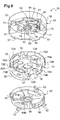
- the piston 50 has, at the front, a piston wall 55, the front face of which forms the front face 50A of the piston 50 (see figures 3 and 6 ).
- This piston wall 55 comprises a disc 54 in which three passage orifices 53 are provided, and a cylindrical wall 56 laterally bordering said disc 54 towards the rear (see figures 3 and 6 ).
- Two of the passage openings 53 of the disc 54 of the piston wall 55 are provided opposite the passage openings 35 of the cover 30 (see figure 3 ) and aligned along the same X axis oriented at 45 ° as the receiving cells 43 of the phase and neutral terminals (see figure 1 ).
- the third passage opening 53 of the disc 54 of the piston wall 55 is opposite the earth pin of the socket outlet 1 (see figure 3 ).
- the piston 50 Under normal conditions of use, the piston 50 is adapted to be pushed backwards, from its high position to its low position, by inserting the pins of the electrical plug into the through holes 53 of the piston wall. 55, which makes it possible to bring the base of the electrical plug into contact with the disc 54 of the piston wall 55 and to exert a pushing force thereon.
- the passage openings 53 of the piston wall 55 In the low activation position, the passage openings 53 of the piston wall 55 extend near the passage openings 35 of the cover 30 so that the pins of the electrical plug can penetrate into the receiving cells 43 of the power outlet 1.
- the socket 1 also comprises means 60 for raising the piston 50 from its low position to its high position (see figures 2 , 3 and 19 ). These means 60 for raising the piston permanently exert a force tending to return the piston 50 to the high position. Thus, as soon as the pins of the electrical plug are removed from the receiving cells 43 of the electrical outlet 1, and the base of the electrical plug is removed from the insertion well 2, the piston 50 automatically rises to its high position. .
- stop lugs 57 here four in number, extending radially outwards from the rear edge of the cylindrical wall 56 of the piston wall 55 (see figure 6 ), and intended to come into abutment against a surface 23 of the cylindrical wall 22 of the hubcap 20, perpendicular to the axis of translation of the piston (see figure 3 ).
- the means 60 for raising the piston 50 are situated exclusively in a space before 1A of the socket, delimited, on the one hand, laterally by said cylindrical wall 22, and, on the other hand, at the rear, by the cover 30 which closes the rear space 1B of the base 10 (see figures 2 and 3 ).
- the front space 1A in which the means 60 for raising the piston 50 are located is itself located inside the front part 10A of the base 10 of the socket outlet 1 (see figure 3 ).
- the means 60 for raising the piston 50 thus disposed in the front space 1A leave the rear space 1B of the base 10 fully available for arranging the connection terminals 40 so that, on the one hand, the receiving cells 43 are aligned along the X axis, oriented at 45 ° relative to the usual horizontal axis H, and, on the other hand, the contact blades 42 extend transversely from one side to the other of the base 10 for connection lateral of said connection terminals 40.
- the means 60 for raising the piston 50 do not present any risk of interference with the connection terminals 40 of the socket outlet 1.
- the means 60 for raising the piston 50 more specifically comprise at least one compression spring 61; 63 which extends along the axis of translation of the piston 50 (see figures 2 , 3 and 19 ).
- This compression spring 61; 63 has a rear end 62; 65 which bears against the front face 30A; 90A of the cover 30; 90, and a front end 64; 67 which bears against part of the piston 50 (see figures 3 and 19 ), so that said compression spring 61; 63 is interposed between the cover 30; 90 and the piston 50 to permanently push the piston 50 back to its high position.
- the compression spring 61 is unique and extends along the axis of revolution R of said cylindrical wall 22. It has a cross section, in a plane perpendicular to said axis of revolution R, the diameter of which is here much less than the diameter of the cross section of the cylindrical wall 22.
- a rear portion of the spring is housed in a housing 37 of the cover 30 which keeps it in place even when it is compressed (see figure 3 ). More precisely, the cover 30 carries a cylindrical sleeve 38 which extends forward and laterally delimits the cylindrical housing 37 (see figures 2 to 4 ) receiving the rear portion of the compression spring 61.
- the rear end 62 of the compression spring 61 then bears against a bearing surface 39 formed by the bottom of the housing 37 (see figures 3 and 4 ), so that said compression spring 61 is held in the front space 1A previously defined, whatever the position of the piston 50.
- a front portion of said compression spring 61 is wound around a central rod 58 of the piston wall 55 (see figure 3 ) extending behind the disc 54 of the piston wall 55, perpendicular to this disc 54, along the axis of revolution R of the cylindrical wall 22 of the hubcap 20 (see figure 6 ).
- the bottom of the housing 37 delimited by the sleeve 38 is pierced with a passage opening 32 provided to let part of said central rod 58 pass (see figures 3 and 4 ).
- part of the central rod 58 of the piston wall 55 then extends into the rear space 1B of the base 10, the assembly of the compression spring 61 being wound around of the part of the central rod 58 still located in the front space 1A.
- the length of the central rod 58 is such that when the piston 50 is in the low position, it sinks into the central part of the rear space 1B without interfering with the electrical contact elements, its free end remaining at above the contact strips 42 which extend against the bottom wall 11 of the base 10 (see figure 3 ).
- the disc 54 also carries, at the rear, two studs 52 in an arc surrounding the rod and delimiting a housing in which the front portion of the compression spring 61 is maintained (see figure 6 ).
- the compression spring 63 is also unique and extends along the axis of revolution R of said cylindrical wall 22. It has a cross section, in a plane perpendicular to said axis of revolution R, the diameter of which is practically equal, apart from play, to the internal diameter of said cylindrical wall 22, so that said compression spring 63 is a peripheral spring which runs along the internal face 22A of the cylindrical wall 22 .
- the compression spring 63 according to this second embodiment is close enough to the cylindrical wall 22 so as not to risk moving or off-axis when it is compressed.
- This configuration makes it possible to have great stability during the displacement of the piston 50. It is then not necessary to provide special arrangements making it possible to guide or hold in place the compression spring when it is compressed.
- the cover 90 of the socket 1 according to the second embodiment is identical in all respects to the cover 30 according to the first embodiment except that it does not have a central housing intended to hold the spring compression in position during compression.
- the piston wall does not have a central rod intended to hold the spring in place during its compression.
- a single central spring, of intermediate section that is to say whose diameter is strictly less than that of the cross section of the cylindrical wall, without necessarily being much less than the latter.
- a spring is for example arranged around the openings of the cover allowing the passage of the ground pin or the access to the phase and neutral terminals, while being sufficiently distant from the cylindrical wall so as not to be able to bear against this last and use it as a guide when compressing. It is then necessary to provide on the cover a housing receiving the rear end of this spring, for example a cylindrical groove in which the rear end of the spring is housed, to prevent any displacement of the spring during its compression. A similar groove could be provided on the rear face of the piston wall to hold the front end of the spring in place during its compression.
- the means for raising the piston include two compression springs which extend on either side of the axis of revolution of the cylindrical wall, and the respective rear ends of which are housed in two housings of the cover.
- This third embodiment is very similar to the first embodiment, except that in place of a single central compression spring, two compression springs are provided, arranged symmetrically with respect to the axis of revolution of the cylindrical wall, so that said piston is not unbalanced during its displacement towards its low position.
- the arrangements for guiding the springs in compression and preventing them from being offset are then similar to those provided in the first embodiment of the socket outlet (housing on the cover and rod at the rear of the wall piston), except that these arrangements are split so that such arrangements are provided for each of the two compression springs.
- a shutter 71 housed in the piston 50 and intended to close the passage orifices 53 of the piston wall 55 , and, on the other hand, locking means 82, 84 of the piston 50 in the high position (see figures 2 and 3 ).
- the piston 50 comprises in particular a cassette 70 housing the shutter 71, attached to the rear of the disc 54 of the piston wall 55 so as to be integral in translation with said piston wall 55 (see figure 6 ).
- This cassette 70 is in the form of a box open at the front, comprising a bottom wall 77 from which rises a side wall 79, bordered at the front, by a sidewalk 79A of circular outline ( see figure 6 ).
- the side edge of the sidewalk 79A of the cassette 70 has four protrusions 72A projecting outwardly and intended to cooperate in force with the internal face of the cylindrical wall 56 of the piston wall 55 (see figure 6 ).
- Four legs 72B extend rearwards from the side edge of said sidewalk 79A and are intended to rest on complementary protrusions 59 provided on the internal face of the cylindrical wall 56 of the piston wall 55 to avoid separation towards the rear of the cassette 70 and the piston wall 55 (see figure 6 ).
- the bottom wall 77 of the cassette 70 is pierced with two circular openings 73B (see figure 6 ) arranged opposite, on the one hand, passage openings 35 of the cover 30, and, on the other hand, passage openings 53 of the disc 54 of the piston wall 55 (see figure 3 ).
- the bottom wall 77 of the cassette 70 is also pierced with a central opening 73C allowing the passage of the lifting means 60 of the piston, in particular of the central rod 58 of the disc 54 and of the compression spring 61 (see figure 3 ).
- the shutter 71 is mounted movably in the cassette 70, between a closed position (see figures 3 and 7 ) in which it prohibits access to the phase and neutral terminals, by interposing between the passage orifices 53 of the disc 54 of the piston wall 55 and the circular openings 73B of the cassette 70 which communicate with the openings of passage 35 of the cover 30, and an open position (not shown) in which it allows this access.
- the shutter 71 thus protects the user from any electrical contact with the conductive elements housed in the rear part 10B of the base 10 of the socket outlet 1.
- the shutter 71 is here in the form of a helix (see figures 3 and 6 ) pivotally mounted in the cassette 70 of the piston 50, the blades of which each have, on the front face, an inclined face of inverted slope.
- the shutter 71 has a return means, here in the form of a spring leaf 74 (see figure 6 ), intended to automatically return the shutter 71 to the closed position.
- This spring leaf 74 permanently exerts a pushing force tending to push the shutter 71 in the closed position against two stop pads 75 extending behind the disc 54 of the piston wall 55.
- the locking means 82, 84 of the piston 50 in the high position intervene between the piston 50 and the cylindrical wall 22 of the hubcap 20 (see figure 3 , 11 and 15 ). They are therefore located in the front part 10A of the base 10 of the power outlet 1.
- Said locking means 82, 84 of the piston 50 in position high comprise, on the one hand, at least two tabs 82 belonging to said piston 50, and, on the other hand, at least two notches 84 formed in the internal face of the cylindrical wall 22, intended to receive said tabs 82.
- the piston 50 comprises in particular a locking wheel 80, attached to the rear of the cassette 70 of the piston 50 and carrying four tabs 82 of generally parallelepiped shape, which extend radially outwards from the locking wheel 80 in being two to two diametrically opposite (see figure 6 ).
- notches 84 formed in the internal face of the cylindrical wall 22 (see figures 11 to 13 ). These notches 84, of complementary shape to the section of the lugs 82 of the locking wheel, that is to say here of rectangular shape, extend generally orthogonally to the direction of translation of the piston (see Figures 11 and 15 ). Each notch 84 of the cylindrical wall forms a retaining surface 83 perpendicular to the direction of translation of the piston, against which the tab 82 of the locking wheel 80 is engaged, engaged in said notch 84 to block the translation of the piston 50 from its high position towards its low position (see figure 15 ).
- the locking wheel 80 is adapted to pivot around the axis of revolution R of the cylindrical wall 22 of the hubcap 20 (see figure 3 ), between a locking position in which each tab 82 is engaged in a notch 84 and bears against the retaining surface 83 of this notch 84 (see figure 15 ), and an unlocking position in which each tab 82 is released from said retaining surface 83 of the notch 84 to allow translation of the piston 50 between its high and low positions (see figure 18 ).
- the locking wheel 80 is mounted on the cassette 70 so as to be integral in translation with said cassette 70, while being free in pivoting relative to said cassette 70 which is, in turn, fixedly mounted in pivoting on the piston wall 55.
- the cassette 70 carries for this purpose, at the rear of its sidewalk 79A, two hooking tabs 76 (see figure 6 ) extending diametrically back-to-back, perpendicular to said sidewalk 79A of the cassette 70, each terminated by a hooking tooth 76A intended to snap into place behind a retaining surface 86 of the wheel blocking 80 (see figures 3 and 6 ).
- Each hooking tooth 76A is sufficiently short relative to the length of the retaining surface 86 to be able to move along this retaining surface 86 and authorize the pivoting of the locking wheel 80.
- two low walls 81A are also provided in an arc extending in the rear of the wall bottom 77 of the cassette 70, bordering on both sides the central opening 73C of the cassette, and intended to cooperate with notches 81B in corresponding arc of the locking wheel 80 (see figure 6 ).
- Each notch 84 of the cylindrical wall 22 of the hubcap 20 communicates with a guide groove 26 formed in said cylindrical wall 22, extending along the axis of translation of the piston (see figures 11 to 14 ).
- Each guide groove 26 is intended to receive one of the lugs 82 of the locking wheel 80 when the latter reaches its unlocking position (see Figures 14 and 18 ). The cooperation of each tab 82 of the locking wheel 80 with the corresponding guide groove 26 guides the piston 50 in translation between its high and low positions.
- the locking wheel 80 is pivotally driven by the pivoting of the shutter 71 from its closed position to its open position, following the insertion of the pins. the electrical plug in the through holes 53 of the piston wall 55.
- the shutter 71 comprises for this purpose (see figure 6 ) drive means 78 adapted, during its movement from its closed position to its open position, to rotate the locking wheel 80 from its locking position to its unlocking position.
- the shutter 71 here carries two drive tabs 78 extending parallel to the direction of translation of the piston, facing one another, on either side of the central rod 58 of the disc 54 of the piston wall 55, between the studs 52 in an arc of a circle carried by said disc 54 (see figure 6 ).
- said blocking means 82, 84 of the piston 50 in the high position are also automatically disengageable in the event of an impact. acting on a front face 50A of the piston 50, and combine with energy dissipation means 27, dissipating the energy acquired by the piston 50 during this shock in order to limit the recoil of the piston 50 in said well. insertion 2 after this shock.
- the socket 1 remains intact and is not damaged when it receives a shock on the front face 50A of its piston 50.
- the dimension of the retaining surface 83 of the notch 84 provided in the cylindrical wall 22 of the hubcap 20 is such that the tab 82 of the locking wheel 80 disengages from said notch 84 when the impact occurs.
- on the front face 50A of the piston 50 is of the IK7 type (see figure 15 ).
- An IK7 type shock is defined by the standard “NF EN 62262” and corresponds to an impact force associated with the fall of a mass of 0.5 kg from a height of 400mm, that is to say an energy transmitted to the piston. about 2 Joules.
- the dimension of the retaining surface 83 of the notch 84 considered is the length L1 of the retaining surface 83 in a direction tangent to said cylindrical wall 22, in a cross section of said insertion well 2 (see figure 15 ).
- Each tab 82 of the locking wheel 80 also has a rounded angle 85 (see figures 15 to 18 ). This rounded angle 85 is intended to slide against said retaining surface 83 of the notch 84 to facilitate the disengagement of said tab 82 from the notch 84, when the shock occurring on the front face 50A of the piston 50 is of the IK7 type.
- each tab 82 of the locking wheel 80 of the piston 50 is made of rigid plastic material, undeformable by an impact of IK7 type occurring on the front face 50A of the piston 50.
- the tab 82 is automatically disengageable, it that is, it comes out of the notch 84 for an IK7 type shock, without breaking.
- each notch 84 and the corresponding guide groove 26 is achieved by means of a ramp 27, that is to say of an inclined surface, forming a contact surface against which the tab 82 of the locking wheel 80 slides to be braked before it engages in said guide groove 26.
- the contact surface formed by the ramp 27 is for example chosen to be concave, facing the front of the socket 1 (see figure 15 ). This shape makes it possible to further slow down the piston 50 before the lugs 82 of the locking wheel 80 engage in the guide grooves 26.
- the length of the contact surface formed by the ramp 27 is such that, for an IK7 type impact, the speed of movement of the piston 50 in the guide groove 26 is strictly less than a threshold speed at which the piston 50 deteriorates the power outlet 1.
- the junction between the notch 84 and the ramp 27 is smooth, without stopping or breaking.
- the meeting line between the notch 84 and the ramp 27 is rounded and not angular. This configuration facilitates automatic disengagement of the locking means, the rounded tab 82 of the locking wheel 80 sliding more easily out of the notch 84 of the cylindrical wall 22.
- the shutter 71 remains in the closed position.
- the pivoting of the locking wheel 80 from its locking position to its unlocking position caused by the impact received on the front face 50A, does not cause the pivoting of the shutter 71 from its closed position towards its open position.
- the return means 89 of the locking wheel 80 in the locking position is here formed by a compression spring 89 interposed between a bearing surface 89A of the cassette 70 and a bearing surface 89B of the locking wheel 80 ( see figure 6 ).
- this compression spring 89 is housed in a housing delimited, at the front, by the sidewalk 79A of the cassette 70, at the rear, by the locking wheel 80, and, laterally, on the one hand, by a wall 87 extending at the rear of the sidewalk 79A of the cassette 70 and the curved end of which forms the bearing surface 89A of the cassette, and on the other hand, by the cylindrical wall 56 of the wall of piston 55, and the bearing surface 89B of the locking wheel 80.
- the ramp communicating the notch and the guide groove has a flat surface instead of concave.
- the surface of this ramp would then be coated with a non-slip coating to brake the piston before it arrives in the guide groove.
- the shutter is mounted in the movable cassette in translation along an axis orthogonal to both the translation axis of the piston and the axis oriented at 45 ° along which the receiving cells are aligned.
- a mechanical system making it possible to transform a translational movement into a rotational movement would then be used between the shutter and the locking wheel so that the movement of the shutter from its closed position to its open position results, under conditions normal use, unlocking the locking wheel.
Landscapes
- Connector Housings Or Holding Contact Members (AREA)
Applications Claiming Priority (1)
| Application Number | Priority Date | Filing Date | Title |
|---|---|---|---|
| FR1860209A FR3088146B1 (fr) | 2018-11-06 | 2018-11-06 | Prise de courant |
Publications (3)
| Publication Number | Publication Date |
|---|---|
| EP3651277A1 true EP3651277A1 (de) | 2020-05-13 |
| EP3651277C0 EP3651277C0 (de) | 2023-08-16 |
| EP3651277B1 EP3651277B1 (de) | 2023-08-16 |
Family
ID=65763570
Family Applications (1)
| Application Number | Title | Priority Date | Filing Date |
|---|---|---|---|
| EP19203372.8A Active EP3651277B1 (de) | 2018-11-06 | 2019-10-15 | Steckdose |
Country Status (3)
| Country | Link |
|---|---|
| EP (1) | EP3651277B1 (de) |
| ES (1) | ES2963435T3 (de) |
| FR (1) | FR3088146B1 (de) |
Cited By (3)
| Publication number | Priority date | Publication date | Assignee | Title |
|---|---|---|---|---|
| EP3945642A1 (de) * | 2020-07-30 | 2022-02-02 | Berker GmbH & Co. KG | Steckdose mit einem basisteil, einer ästhetischen abdeckung und einem antriebselement für eine bewegliche abdeckung der ästhetischen abdeckung |
| EP4170829A1 (de) * | 2021-10-22 | 2023-04-26 | H.B.F. | Steckdose mit erleichtertem ein- und ausziehen |
| EP4478558A1 (de) * | 2023-06-15 | 2024-12-18 | Schneider Electric España, S.A. | Elektrische steckdose |
Citations (6)
| Publication number | Priority date | Publication date | Assignee | Title |
|---|---|---|---|---|
| DE29918007U1 (de) * | 1998-11-16 | 1999-12-16 | Delta Electronics, Inc., Taoyuan | Sicherheitsstecker |
| FR2978876A1 (fr) * | 2011-08-04 | 2013-02-08 | Legrand France | Prise de courant equipee de deux obturateurs |
| US20150104960A1 (en) * | 2013-10-10 | 2015-04-16 | Jong Il Kim | Safe outlet |
| EP3043424A1 (de) * | 2015-01-06 | 2016-07-13 | Kim, Jong-il | Elektrische steckdose |
| KR101691718B1 (ko) | 2015-02-12 | 2017-01-09 | 정창원 | 안전 콘센트 |
| KR20170029216A (ko) | 2015-09-07 | 2017-03-15 | 배봉관 | 콘센트 안전장치 |
-
2018
- 2018-11-06 FR FR1860209A patent/FR3088146B1/fr active Active
-
2019
- 2019-10-15 EP EP19203372.8A patent/EP3651277B1/de active Active
- 2019-10-15 ES ES19203372T patent/ES2963435T3/es active Active
Patent Citations (6)
| Publication number | Priority date | Publication date | Assignee | Title |
|---|---|---|---|---|
| DE29918007U1 (de) * | 1998-11-16 | 1999-12-16 | Delta Electronics, Inc., Taoyuan | Sicherheitsstecker |
| FR2978876A1 (fr) * | 2011-08-04 | 2013-02-08 | Legrand France | Prise de courant equipee de deux obturateurs |
| US20150104960A1 (en) * | 2013-10-10 | 2015-04-16 | Jong Il Kim | Safe outlet |
| EP3043424A1 (de) * | 2015-01-06 | 2016-07-13 | Kim, Jong-il | Elektrische steckdose |
| KR101691718B1 (ko) | 2015-02-12 | 2017-01-09 | 정창원 | 안전 콘센트 |
| KR20170029216A (ko) | 2015-09-07 | 2017-03-15 | 배봉관 | 콘센트 안전장치 |
Cited By (3)
| Publication number | Priority date | Publication date | Assignee | Title |
|---|---|---|---|---|
| EP3945642A1 (de) * | 2020-07-30 | 2022-02-02 | Berker GmbH & Co. KG | Steckdose mit einem basisteil, einer ästhetischen abdeckung und einem antriebselement für eine bewegliche abdeckung der ästhetischen abdeckung |
| EP4170829A1 (de) * | 2021-10-22 | 2023-04-26 | H.B.F. | Steckdose mit erleichtertem ein- und ausziehen |
| EP4478558A1 (de) * | 2023-06-15 | 2024-12-18 | Schneider Electric España, S.A. | Elektrische steckdose |
Also Published As
| Publication number | Publication date |
|---|---|
| FR3088146A1 (fr) | 2020-05-08 |
| EP3651277C0 (de) | 2023-08-16 |
| ES2963435T3 (es) | 2024-03-27 |
| FR3088146B1 (fr) | 2023-10-27 |
| EP3651277B1 (de) | 2023-08-16 |
Similar Documents
| Publication | Publication Date | Title |
|---|---|---|
| EP2456024B1 (de) | Stromsteckdose mit Verschlussvorrichtung | |
| EP2555336B1 (de) | Steckdose, die mit zwei Deckeln ausgestattet ist | |
| CA2349692C (fr) | Dispositif de blocage d'aubes a attache marteau sur un disque | |
| EP3651277B1 (de) | Steckdose | |
| EP3103164B1 (de) | Steckverbinder und entsprechende verbinderanordnung | |
| EP2752946B1 (de) | Elektrischer Anschluss mit automatischer Blockierung | |
| FR2716594A1 (fr) | Support pour radiotéléphone portatif . | |
| EP2654137A1 (de) | Sockel eines Multikontaktanschlusses zum Schnellbefestigen auf einer Platte und entsprechendes Montage-/Demontage-Verfahren | |
| EP2456021B1 (de) | Stromsteckdose mit seitlichen verschiebbaren Balken | |
| EP3138166B1 (de) | Elektromodul zum einschnappen in eine elektrodose | |
| FR3088145A1 (fr) | Prise de courant | |
| EP3503322B1 (de) | Halterung für elektrische geräte, die ein montagelement aufnimmt | |
| EP2456032A1 (de) | Vorrichtung zum Verstauen von Stromkabeln | |
| EP4508724A1 (de) | Elektrische buchse mit einem beweglichen stössel | |
| EP2515391B1 (de) | Mehrfachgeräteblock, der mit einem verschiebbaren Zubehörteil ausgestattet ist | |
| EP2515390B1 (de) | Mehrfachgeräteblock, der mit Mitteln zur Befestigung an der Wand ausgestattet ist | |
| EP2715894B1 (de) | Zugangsklappe für elektrogeräte | |
| EP3651278B1 (de) | Steckdose mit leuchtquelle | |
| EP4243219B1 (de) | Standardsteckdose mit sicherheitsverstärkten seitenerdkontakten | |
| EP1286427A1 (de) | Reihenklemme mit Verriegelungshebel für Steckverbinder | |
| EP4657673A1 (de) | Frontteil für einen stromabnehmer und steckdose | |
| EP2434598A1 (de) | Elektrisches verschiebbares Zubehör, das in eine Wandöffnung eingebaut ist | |
| FR3037436A1 (fr) | Coupe-circuit electrique a commande manuelle | |
| FR2874131A1 (fr) | Support de connecteur |
Legal Events
| Date | Code | Title | Description |
|---|---|---|---|
| PUAI | Public reference made under article 153(3) epc to a published international application that has entered the european phase |
Free format text: ORIGINAL CODE: 0009012 |
|
| STAA | Information on the status of an ep patent application or granted ep patent |
Free format text: STATUS: THE APPLICATION HAS BEEN PUBLISHED |
|
| AK | Designated contracting states |
Kind code of ref document: A1 Designated state(s): AL AT BE BG CH CY CZ DE DK EE ES FI FR GB GR HR HU IE IS IT LI LT LU LV MC MK MT NL NO PL PT RO RS SE SI SK SM TR |
|
| AX | Request for extension of the european patent |
Extension state: BA ME |
|
| STAA | Information on the status of an ep patent application or granted ep patent |
Free format text: STATUS: REQUEST FOR EXAMINATION WAS MADE |
|
| 17P | Request for examination filed |
Effective date: 20200626 |
|
| RBV | Designated contracting states (corrected) |
Designated state(s): AL AT BE BG CH CY CZ DE DK EE ES FI FR GB GR HR HU IE IS IT LI LT LU LV MC MK MT NL NO PL PT RO RS SE SI SK SM TR |
|
| STAA | Information on the status of an ep patent application or granted ep patent |
Free format text: STATUS: EXAMINATION IS IN PROGRESS |
|
| 17Q | First examination report despatched |
Effective date: 20210618 |
|
| GRAP | Despatch of communication of intention to grant a patent |
Free format text: ORIGINAL CODE: EPIDOSNIGR1 |
|
| STAA | Information on the status of an ep patent application or granted ep patent |
Free format text: STATUS: GRANT OF PATENT IS INTENDED |
|
| RIC1 | Information provided on ipc code assigned before grant |
Ipc: H01R 24/76 20110101ALN20230301BHEP Ipc: H01R 13/453 20060101AFI20230301BHEP |
|
| INTG | Intention to grant announced |
Effective date: 20230316 |
|
| GRAS | Grant fee paid |
Free format text: ORIGINAL CODE: EPIDOSNIGR3 |
|
| GRAA | (expected) grant |
Free format text: ORIGINAL CODE: 0009210 |
|
| STAA | Information on the status of an ep patent application or granted ep patent |
Free format text: STATUS: THE PATENT HAS BEEN GRANTED |
|
| AK | Designated contracting states |
Kind code of ref document: B1 Designated state(s): AL AT BE BG CH CY CZ DE DK EE ES FI FR GB GR HR HU IE IS IT LI LT LU LV MC MK MT NL NO PL PT RO RS SE SI SK SM TR |
|
| REG | Reference to a national code |
Ref country code: CH Ref legal event code: EP |
|
| REG | Reference to a national code |
Ref country code: DE Ref legal event code: R096 Ref document number: 602019034996 Country of ref document: DE |
|
| REG | Reference to a national code |
Ref country code: IE Ref legal event code: FG4D Free format text: LANGUAGE OF EP DOCUMENT: FRENCH |
|
| U01 | Request for unitary effect filed |
Effective date: 20230828 |
|
| U07 | Unitary effect registered |
Designated state(s): AT BE BG DE DK EE FI FR IT LT LU LV MT NL PT SE SI Effective date: 20230904 |
|
| U20 | Renewal fee for the european patent with unitary effect paid |
Year of fee payment: 5 Effective date: 20231003 |
|
| PG25 | Lapsed in a contracting state [announced via postgrant information from national office to epo] |
Ref country code: GR Free format text: LAPSE BECAUSE OF FAILURE TO SUBMIT A TRANSLATION OF THE DESCRIPTION OR TO PAY THE FEE WITHIN THE PRESCRIBED TIME-LIMIT Effective date: 20231117 |
|
| PG25 | Lapsed in a contracting state [announced via postgrant information from national office to epo] |
Ref country code: IS Free format text: LAPSE BECAUSE OF FAILURE TO SUBMIT A TRANSLATION OF THE DESCRIPTION OR TO PAY THE FEE WITHIN THE PRESCRIBED TIME-LIMIT Effective date: 20231216 |
|
| PG25 | Lapsed in a contracting state [announced via postgrant information from national office to epo] |
Ref country code: RS Free format text: LAPSE BECAUSE OF FAILURE TO SUBMIT A TRANSLATION OF THE DESCRIPTION OR TO PAY THE FEE WITHIN THE PRESCRIBED TIME-LIMIT Effective date: 20230816 Ref country code: NO Free format text: LAPSE BECAUSE OF FAILURE TO SUBMIT A TRANSLATION OF THE DESCRIPTION OR TO PAY THE FEE WITHIN THE PRESCRIBED TIME-LIMIT Effective date: 20231116 Ref country code: IS Free format text: LAPSE BECAUSE OF FAILURE TO SUBMIT A TRANSLATION OF THE DESCRIPTION OR TO PAY THE FEE WITHIN THE PRESCRIBED TIME-LIMIT Effective date: 20231216 Ref country code: HR Free format text: LAPSE BECAUSE OF FAILURE TO SUBMIT A TRANSLATION OF THE DESCRIPTION OR TO PAY THE FEE WITHIN THE PRESCRIBED TIME-LIMIT Effective date: 20230816 Ref country code: GR Free format text: LAPSE BECAUSE OF FAILURE TO SUBMIT A TRANSLATION OF THE DESCRIPTION OR TO PAY THE FEE WITHIN THE PRESCRIBED TIME-LIMIT Effective date: 20231117 |
|
| PG25 | Lapsed in a contracting state [announced via postgrant information from national office to epo] |
Ref country code: PL Free format text: LAPSE BECAUSE OF FAILURE TO SUBMIT A TRANSLATION OF THE DESCRIPTION OR TO PAY THE FEE WITHIN THE PRESCRIBED TIME-LIMIT Effective date: 20230816 |
|
| REG | Reference to a national code |
Ref country code: ES Ref legal event code: FG2A Ref document number: 2963435 Country of ref document: ES Kind code of ref document: T3 Effective date: 20240327 |
|
| PG25 | Lapsed in a contracting state [announced via postgrant information from national office to epo] |
Ref country code: SM Free format text: LAPSE BECAUSE OF FAILURE TO SUBMIT A TRANSLATION OF THE DESCRIPTION OR TO PAY THE FEE WITHIN THE PRESCRIBED TIME-LIMIT Effective date: 20230816 Ref country code: RO Free format text: LAPSE BECAUSE OF FAILURE TO SUBMIT A TRANSLATION OF THE DESCRIPTION OR TO PAY THE FEE WITHIN THE PRESCRIBED TIME-LIMIT Effective date: 20230816 Ref country code: CZ Free format text: LAPSE BECAUSE OF FAILURE TO SUBMIT A TRANSLATION OF THE DESCRIPTION OR TO PAY THE FEE WITHIN THE PRESCRIBED TIME-LIMIT Effective date: 20230816 Ref country code: SK Free format text: LAPSE BECAUSE OF FAILURE TO SUBMIT A TRANSLATION OF THE DESCRIPTION OR TO PAY THE FEE WITHIN THE PRESCRIBED TIME-LIMIT Effective date: 20230816 |
|
| REG | Reference to a national code |
Ref country code: DE Ref legal event code: R097 Ref document number: 602019034996 Country of ref document: DE |
|
| PG25 | Lapsed in a contracting state [announced via postgrant information from national office to epo] |
Ref country code: MC Free format text: LAPSE BECAUSE OF FAILURE TO SUBMIT A TRANSLATION OF THE DESCRIPTION OR TO PAY THE FEE WITHIN THE PRESCRIBED TIME-LIMIT Effective date: 20230816 |
|
| REG | Reference to a national code |
Ref country code: CH Ref legal event code: PL |
|
| PLBE | No opposition filed within time limit |
Free format text: ORIGINAL CODE: 0009261 |
|
| STAA | Information on the status of an ep patent application or granted ep patent |
Free format text: STATUS: NO OPPOSITION FILED WITHIN TIME LIMIT |
|
| PG25 | Lapsed in a contracting state [announced via postgrant information from national office to epo] |
Ref country code: CH Free format text: LAPSE BECAUSE OF NON-PAYMENT OF DUE FEES Effective date: 20231031 |
|
| 26N | No opposition filed |
Effective date: 20240517 |
|
| GBPC | Gb: european patent ceased through non-payment of renewal fee |
Effective date: 20231116 |
|
| PG25 | Lapsed in a contracting state [announced via postgrant information from national office to epo] |
Ref country code: CH Free format text: LAPSE BECAUSE OF NON-PAYMENT OF DUE FEES Effective date: 20231031 |
|
| PG25 | Lapsed in a contracting state [announced via postgrant information from national office to epo] |
Ref country code: IE Free format text: LAPSE BECAUSE OF NON-PAYMENT OF DUE FEES Effective date: 20231015 |
|
| PG25 | Lapsed in a contracting state [announced via postgrant information from national office to epo] |
Ref country code: GB Free format text: LAPSE BECAUSE OF NON-PAYMENT OF DUE FEES Effective date: 20231116 |
|
| U20 | Renewal fee for the european patent with unitary effect paid |
Year of fee payment: 6 Effective date: 20240919 |
|
| PG25 | Lapsed in a contracting state [announced via postgrant information from national office to epo] |
Ref country code: IE Free format text: LAPSE BECAUSE OF NON-PAYMENT OF DUE FEES Effective date: 20231015 Ref country code: GB Free format text: LAPSE BECAUSE OF NON-PAYMENT OF DUE FEES Effective date: 20231116 |
|
| PG25 | Lapsed in a contracting state [announced via postgrant information from national office to epo] |
Ref country code: CY Free format text: LAPSE BECAUSE OF FAILURE TO SUBMIT A TRANSLATION OF THE DESCRIPTION OR TO PAY THE FEE WITHIN THE PRESCRIBED TIME-LIMIT; INVALID AB INITIO Effective date: 20191015 |
|
| PG25 | Lapsed in a contracting state [announced via postgrant information from national office to epo] |
Ref country code: HU Free format text: LAPSE BECAUSE OF FAILURE TO SUBMIT A TRANSLATION OF THE DESCRIPTION OR TO PAY THE FEE WITHIN THE PRESCRIBED TIME-LIMIT; INVALID AB INITIO Effective date: 20191015 |
|
| U20 | Renewal fee for the european patent with unitary effect paid |
Year of fee payment: 7 Effective date: 20250923 |
|
| PG25 | Lapsed in a contracting state [announced via postgrant information from national office to epo] |
Ref country code: TR Free format text: LAPSE BECAUSE OF FAILURE TO SUBMIT A TRANSLATION OF THE DESCRIPTION OR TO PAY THE FEE WITHIN THE PRESCRIBED TIME-LIMIT Effective date: 20230816 |
|
| PGFP | Annual fee paid to national office [announced via postgrant information from national office to epo] |
Ref country code: ES Payment date: 20251103 Year of fee payment: 7 |