EP3651465A1 - Contrôle de la consommation de largeur de bande de mémoire de mode affine en codage vidéo polyvalent - Google Patents
Contrôle de la consommation de largeur de bande de mémoire de mode affine en codage vidéo polyvalent Download PDFInfo
- Publication number
- EP3651465A1 EP3651465A1 EP19207520.8A EP19207520A EP3651465A1 EP 3651465 A1 EP3651465 A1 EP 3651465A1 EP 19207520 A EP19207520 A EP 19207520A EP 3651465 A1 EP3651465 A1 EP 3651465A1
- Authority
- EP
- European Patent Office
- Prior art keywords
- motion compensation
- reference block
- affine
- size
- prediction
- Prior art date
- Legal status (The legal status is an assumption and is not a legal conclusion. Google has not performed a legal analysis and makes no representation as to the accuracy of the status listed.)
- Pending
Links
Images






Classifications
-
- H—ELECTRICITY
- H04—ELECTRIC COMMUNICATION TECHNIQUE
- H04N—PICTORIAL COMMUNICATION, e.g. TELEVISION
- H04N19/00—Methods or arrangements for coding, decoding, compressing or decompressing digital video signals
- H04N19/10—Methods or arrangements for coding, decoding, compressing or decompressing digital video signals using adaptive coding
- H04N19/102—Methods or arrangements for coding, decoding, compressing or decompressing digital video signals using adaptive coding characterised by the element, parameter or selection affected or controlled by the adaptive coding
- H04N19/103—Selection of coding mode or of prediction mode
- H04N19/105—Selection of the reference unit for prediction within a chosen coding or prediction mode, e.g. adaptive choice of position and number of pixels used for prediction
-
- H—ELECTRICITY
- H04—ELECTRIC COMMUNICATION TECHNIQUE
- H04N—PICTORIAL COMMUNICATION, e.g. TELEVISION
- H04N19/00—Methods or arrangements for coding, decoding, compressing or decompressing digital video signals
- H04N19/50—Methods or arrangements for coding, decoding, compressing or decompressing digital video signals using predictive coding
- H04N19/503—Methods or arrangements for coding, decoding, compressing or decompressing digital video signals using predictive coding involving temporal prediction
- H04N19/51—Motion estimation or motion compensation
- H04N19/537—Motion estimation other than block-based
-
- H—ELECTRICITY
- H04—ELECTRIC COMMUNICATION TECHNIQUE
- H04N—PICTORIAL COMMUNICATION, e.g. TELEVISION
- H04N19/00—Methods or arrangements for coding, decoding, compressing or decompressing digital video signals
- H04N19/10—Methods or arrangements for coding, decoding, compressing or decompressing digital video signals using adaptive coding
- H04N19/102—Methods or arrangements for coding, decoding, compressing or decompressing digital video signals using adaptive coding characterised by the element, parameter or selection affected or controlled by the adaptive coding
- H04N19/12—Selection from among a plurality of transforms or standards, e.g. selection between discrete cosine transform [DCT] and sub-band transform or selection between H.263 and H.264
- H04N19/122—Selection of transform size, e.g. 8x8 or 2x4x8 DCT; Selection of sub-band transforms of varying structure or type
-
- H—ELECTRICITY
- H04—ELECTRIC COMMUNICATION TECHNIQUE
- H04N—PICTORIAL COMMUNICATION, e.g. TELEVISION
- H04N19/00—Methods or arrangements for coding, decoding, compressing or decompressing digital video signals
- H04N19/10—Methods or arrangements for coding, decoding, compressing or decompressing digital video signals using adaptive coding
- H04N19/134—Methods or arrangements for coding, decoding, compressing or decompressing digital video signals using adaptive coding characterised by the element, parameter or criterion affecting or controlling the adaptive coding
- H04N19/157—Assigned coding mode, i.e. the coding mode being predefined or preselected to be further used for selection of another element or parameter
- H04N19/159—Prediction type, e.g. intra-frame, inter-frame or bidirectional frame prediction
-
- H—ELECTRICITY
- H04—ELECTRIC COMMUNICATION TECHNIQUE
- H04N—PICTORIAL COMMUNICATION, e.g. TELEVISION
- H04N19/00—Methods or arrangements for coding, decoding, compressing or decompressing digital video signals
- H04N19/10—Methods or arrangements for coding, decoding, compressing or decompressing digital video signals using adaptive coding
- H04N19/169—Methods or arrangements for coding, decoding, compressing or decompressing digital video signals using adaptive coding characterised by the coding unit, i.e. the structural portion or semantic portion of the video signal being the object or the subject of the adaptive coding
- H04N19/17—Methods or arrangements for coding, decoding, compressing or decompressing digital video signals using adaptive coding characterised by the coding unit, i.e. the structural portion or semantic portion of the video signal being the object or the subject of the adaptive coding the unit being an image region, e.g. an object
- H04N19/176—Methods or arrangements for coding, decoding, compressing or decompressing digital video signals using adaptive coding characterised by the coding unit, i.e. the structural portion or semantic portion of the video signal being the object or the subject of the adaptive coding the unit being an image region, e.g. an object the region being a block, e.g. a macroblock
-
- H—ELECTRICITY
- H04—ELECTRIC COMMUNICATION TECHNIQUE
- H04N—PICTORIAL COMMUNICATION, e.g. TELEVISION
- H04N19/00—Methods or arrangements for coding, decoding, compressing or decompressing digital video signals
- H04N19/42—Methods or arrangements for coding, decoding, compressing or decompressing digital video signals characterised by implementation details or hardware specially adapted for video compression or decompression, e.g. dedicated software implementation
- H04N19/423—Methods or arrangements for coding, decoding, compressing or decompressing digital video signals characterised by implementation details or hardware specially adapted for video compression or decompression, e.g. dedicated software implementation characterised by memory arrangements
-
- H—ELECTRICITY
- H04—ELECTRIC COMMUNICATION TECHNIQUE
- H04N—PICTORIAL COMMUNICATION, e.g. TELEVISION
- H04N19/00—Methods or arrangements for coding, decoding, compressing or decompressing digital video signals
- H04N19/50—Methods or arrangements for coding, decoding, compressing or decompressing digital video signals using predictive coding
- H04N19/503—Methods or arrangements for coding, decoding, compressing or decompressing digital video signals using predictive coding involving temporal prediction
-
- H—ELECTRICITY
- H04—ELECTRIC COMMUNICATION TECHNIQUE
- H04N—PICTORIAL COMMUNICATION, e.g. TELEVISION
- H04N19/00—Methods or arrangements for coding, decoding, compressing or decompressing digital video signals
- H04N19/50—Methods or arrangements for coding, decoding, compressing or decompressing digital video signals using predictive coding
- H04N19/503—Methods or arrangements for coding, decoding, compressing or decompressing digital video signals using predictive coding involving temporal prediction
- H04N19/51—Motion estimation or motion compensation
-
- H—ELECTRICITY
- H04—ELECTRIC COMMUNICATION TECHNIQUE
- H04N—PICTORIAL COMMUNICATION, e.g. TELEVISION
- H04N19/00—Methods or arrangements for coding, decoding, compressing or decompressing digital video signals
- H04N19/50—Methods or arrangements for coding, decoding, compressing or decompressing digital video signals using predictive coding
- H04N19/503—Methods or arrangements for coding, decoding, compressing or decompressing digital video signals using predictive coding involving temporal prediction
- H04N19/51—Motion estimation or motion compensation
- H04N19/577—Motion compensation with bidirectional frame interpolation, i.e. using B-pictures
Definitions
- One or more aspects of the disclosed subject matter are directed to video encoding or decoding and more specifically to video encoding or decoding with memory bandwidth conservation when an affine motion model is used.
- VVC Very Video Coding
- JVET joint video experts team
- the affine motion compensation prediction introduces a more complex motion model for better compression efficiency.
- previous standards such as HEVC
- a translational motion model is considered, in which all the sample positions inside a PU (prediction unit) may have a same translational motion vector for motion compensated prediction.
- the affine motion model supports different motion vectors at different sample positions inside a PU, which effectively captures more complex motion.
- Different sample positions inside a PU, such as four corner points of the PU may have different motion vectors as supported by the affine mode.
- a PU coded in affine mode and affine merge mode may have uni-prediction (list 0 or list 1 prediction) or bi-directional prediction (i.e. list 0 and list 1 bi-prediction).
- the sub-block size for the affine mode is fixed to 4x4, which creates the 4x4 bi-directional prediction for the worst-case memory bandwidth consumption of motion compensation.
- the worst-case memory bandwidth consumption for motion compensation is 8x8 bidirectional prediction, while 8x4 and 4x8 PUs use uni-prediction only.
- the increased memory bandwidth budget can never catch up with the path of sample rate increase (e.g., HEVC is typically for 4K video at 60 fps, while VVC will be used for 8K video at 60 fps, another factor of 4 increase in terms of sample processing rate).
- a device for video encoding or decoding comprising:
- the circuitry is further configured to calculate the reference block bounding box size by determining coordinates of an upper-left and bottom-right corner of the reference block bounding box of a plurality of consecutive sub-block vectors of the PU, and calculating a width and height of the reference block bounding box based on the coordinates.
- the reference block bounding box size is calculated based on a prediction type being unidirectional prediction or bidirectional prediction.
- the at least one predetermined threshold is set based on a prediction type being unidirectional prediction or bidirectional prediction.
- the circuitry is further configured to calculate the reference block bounding box size to determine whether the reference block bounding size exceeds the at least one predetermined threshold, and perform the first motion compensation operation or the second motion compensation operation in response to a determination separately for list0 and list1 prediction of the PU.
- all sub-block vectors of the PU are set to a same vector, the same vector being an affine motion vector for a single point in the PU.
- an affine sub-block motion vector field for affine motion compensation is generated based on a sub-block size.
- an affine sub-block motion vector field for motion compensation is generated by using a larger sub-block size.
- the circuitry is further configured to select the control point motion vectors for the PU so that the resulting reference block bounding box size does not exceed one or more predetermined thresholds.
- a method of video encoding or decoding comprising:
- the method further comprises: calculating the reference block bounding box size by determining coordinates of an upper-left and bottom-right corner of the reference block bounding box of a plurality of consecutive sub-block vectors of the PU, and calculating a width and height of the reference block bounding box based on the coordinates.
- the method further comprises: calculating the reference block bounding block size based on a prediction type being unidirectional prediction or bidirectional prediction.
- the method further comprises: setting the at least one predetermined threshold based on a prediction type being unidirectional prediction or bidirectional prediction.
- the method further comprises: calculating the reference block bounding box to
- all sub-block vectors of the PU are set to a same vector, the same vector being an affine motion vector for a single point in the PU.
- an affine sub-block motion vector field for affine motion compensation is generated based on a sub-block size.
- an affine sub-block motion vector field for motion compensation is generated by using a larger sub-block size.
- the method further comprises: selecting the control point motion vectors for the PU so that the resulting reference block bounding box size does not exceed one or more predetermined thresholds.
- a non-transitory, computer-readable storage medium storing instructions that, when executed on one or more processors, control the one or more processors to perform a method of video encoding or decoding, comprising:
- the non-transitory, computer-readable storage medium further comprises: calculating the reference block bounding box size by determining coordinates of an upper-left and bottom-right corner of the reference block bounding box of a plurality of consecutive sub-block vectors of the PU, and calculating a width and height of the reference block bounding box based on the coordinates.
- Fig. 1A is a flow chart showing an overview of one or more aspects of the disclosed subject matter.
- step 102 the reference block bounding box size and at least one threshold are determined.
- step 104 it is determined whether the reference block bounding box size exceeds the at least one threshold. If so, the affine motion compensation is performed in step 106 using a first motion compensation operation. In response to a determination that the reference block bounding size does not exceed the predefined threshold, the affine motion compensation is performed in step 108 using a second affine motion compensation operation that is different from the first motion compensation operation. Either way, the results are output in step 110.
- Fig. 1B shows an affine motion model according to one or more aspects of the disclosed subject matter.
- the origin (0, 0) of the x-y coordinate system can be at the top-left corner point of a picture as illustrated in Fig. 1B .
- other drawings in the description having an x-y coordinate system can also have the origin (0, 0) of the x-y coordinate at the top-left corner of a picture.
- a PU coded in affine mode and affine merge mode can have uni-prediction or bi-directional prediction.
- the uni-prediction can correspond to a list 0 or list 1 prediction
- the bi-directional prediction can correspond to a list 0 and list 1 bi-prediction.
- Fig. 1C shows a 4-parameter affine motion model according to one or more aspects of the disclosed subject matter.
- the 4-parameter affine motion model can be a restricted affine motion model because the parameters are restricted.
- the model parameters a, b, e, f are determined by signaling two control point vectors at the top-left and top-right corner of a PU.
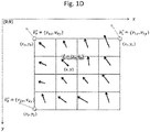
- Fig. ID shows a 6-parameter affine motion model according to one or more aspects of the disclosed subject matter.
- the model parameters for the 6-parameter affine motion model can be determined by signaling three control point vectors at the top-left, top-right, and bottom-left corner of a PU.
- the motion vectors of a PU coded in affine mode are not derived for each sample in a PU.
- all the samples inside a sub-block (e.g. 4x4 block size) of the PU can share a same motion vector.
- Deriving the motion vector can be based on a sub-block motion data derivation process of the affine mode where the motion vector is derived at sample position ( x,y ) chosen for the sub-block and by using Equation 3 or Equation 4, and whether to use Equation 3 or Equation 4 depends on the type of affine motion model.
- the sub-block size is fixed to 4x4 and the sample position chosen for deriving the sub-block motion vector field of a PU coded in affine mode is the center point of each 4x4 sub-block of the PU.
- Fig. 2 shows 4 (i.e. 2x2) sub-block motion vectors in a PU coded in affine mode and bi-directional inter prediction and depicts the geometric relationship of 4 sub-block vectors in a PU coded in affine mode and bi-directional inter prediction.
- the parameters of the affine motion model i.e. ( a, b, c d), can be calculated in any suitable way such as using Equation 3 or 4.
- Fig. 3 shows a reference block bounding box of 4 sub-block motion vectors in a PU coded in affine mode and bidirectional inter prediction. Assuming ( x 0 , y 0 ) are the coordinate of the sub-block 0 in Fig.
- Table 1 Coordinates of upper-left and bottom-right corners of reference blocks of four sub-block vectors
- Table 1 Coordinates of upper-left corner of the sub-block Coordinates of upper-left corner of the reference block Coordinates of bottom-right corner of the reference block 0 ( x 0 , y 0 ) x 0 + v xs 0 ⁇ f x 2 + 1 , y 0 + v ys 0 ⁇ f y 2 + 1 x 0 + v xs 0 + f x 2 + m , y 0 + v ys 0 + f y 2 + n 1 ( x 0 + m ,
- bxH 4 max 0 , bm , 1 + d n , bm + 1 + d n ⁇ min 0 , bm , 1 + d n , bm + 1 + d n + f y + n ⁇ 1
- Fig. 4 shows a reference block bounding box of 2 sub-block motion vectors in a PU coded in affine mode and unidirectional inter prediction (horizontal direction).
- Fig. 5 shows a reference block bounding box of 2 sub-block motion vectors in a PU coded in affine mode and unidirectional inter prediction (vertical direction).
- the reference block bounding box size i.e.
- the reference block bounding block size is independent of sub-block locations inside the PU; it purely depends on the parameters of the affine motion model (i.e. a, b, c, d ) , sub-block size (i.e. m ⁇ n ) and filter tap lengths (i.e. f x ⁇ f y ) used for motion compensation.
- the reference block bounding box sizes for the VVC are defined in Equations 15, 16 and 17.
- Fig. 6 is an algorithmic flow chart of a method for controlling memory bandwidth consumption of the affine mode.
- the decoder Based on the CPMVs (control point motion vectors) received for the PU, the decoder computes the reference block bounding box size and switches to the fallback mode (from the affine mode) if the reference blocking box size exceeds the pre-defined thresholds.
- the reference block bounding box is computed for 2x2 sub-block vectors if the PU uses bidirectional affine mode, and for 2x1 and 1x2 sub-block vectors if the PU uses unidirectional affine mode.
- the following steps may be applied:
- the reference block size for an 8x8 directional PU using 8-tap interpolation filters is 15 ⁇ 15 for both the list0 and list1 prediction
- the reference block size for an 8x4/4x8 unidirectional PU is 15 ⁇ 11/11 ⁇ 15 for list0 or list1 prediction. Those values match the thresholds set in Equation 19.
- Fig. 7 is an algorithmic flow chart of a method for controlling memory bandwidth consumption of the affine mode.
- the decoder Based on the CPMVs (control point motion vectors) received for the PU, the decoder computes the reference block bounding box size and switches to the fallback mode (from the affine mode) if the reference blocking box size exceeds the pre-defined thresholds.
- the reference block bounding box is always computed for 2x2 sub-block vectors independent of the PU prediction type (unidirectional or bidirectional prediction). In one implementation, the following steps may be applied:
- a PU has both list0 and list1 predictions.
- the reference bounding box size bxW 4 ⁇ bxH 4 is computed independently for list0 and list1 prediction with the respective list0/list1 affine motion model parameters (a, b, c, d) of the PU, and the threshold Thred b is set separately for list0 and list1 prediction (though the values of the threshold could be the same).
- the following four combinations are possible for a PU coded in bi-directional affine mode: 1) the regular sub-block motion vector fields are used for both the list0 and list1 motion compensation of the PU; 2) the regular sub-block motion vector field is used for list0 motion compensation but the fallback mode (i.e. a single vector for list1 prediction of the entire PU) is used for list1 motion compensation; 3) the fallback mode (i.e. a single vector for list0 prediction of the entire PU) is used for list0 motion compensation but the regular sub-block motion vector field is used for list1 motion compensation; and 4) the fallback mode (i.e. a first single vector for list0 prediction and a second single vector for list1 prediction of the entire PU) is used for both list0 and list1 motion compensation.
- the fallback mode i.e. a first single vector for list0 prediction and a second single vector for list1 prediction of the entire PU
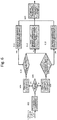
- Fig. 8 is an algorithmic flow chart of a method for controlling the sub-block motion vector spread in the affine motion estimation on the encoder side.
- the basic idea is to constrain the sub-block motion vector spread at PU level.
- the sub-block motion vector spread can be measured by using the reference block bounding box size.
- the encoder guarantees that the affine mode, if it is selected for a PU, has the sub-block motion vector spread constrained to meet the pre-defined budget of the worst-case memory bandwidth consumption at PU level.
- the following steps may be applied:
- the estimated affine CPMVs for the PU may be further evaluated against the costs of regular motion vectors and intra prediction mode estimated for the PU to decide whether the current PU should be encoded in the affine mode.
- the worst-case memory bandwidth consumption for the affine mode is restricted not only at sub-block level but also at PU level.
- the sub-block motion vector spread within a PU of affine mode is determined by the affine parameters ( a, b, c, d ).
- step 810 the decision on whether the reference bounding box size exceeds the pre-defined threshold is done independently for the list0 and list1 prediction of a PU coded in bi-directional affine mode.
- bitstream conforming to the VVC standard shall satisfy the following conditions:
- Fig. 8 just exhibits one example of the embodiment; other variants can be implemented. For example:
- Fig. 9 is an algorithmic flow chart of a method for determining block size.
- the reference block bounding box size and the at least one threshold are determined.
- the reference block bounding box size and the at least one threshold are compared. If the reference block bounding size exceeds the at least one threshold, then in step 906, the sub-block size m ' ⁇ n ' (or as appropriate, m ' ⁇ n or m ⁇ n', with m' > m , and n ' > n ) is used for the generation of the affine sub-block motion vector field and for affine motion compensation. Otherwise, in step 908, the sub-block size m ⁇ n is used. Any combination of bi-directional, horizontal unidirectional and vertical unidirectional modes can be used. The results are output in step 910.
- the memory bandwidth control algorithm can be modified based on the shape of the PU coded in the affine mode:
- sub-block size m ⁇ n is used for the generation of the sub-block motion data field for the motion compensation of the PU.
- the selection may be based on the width and/or height of the reference block bounding box, and/or based on the DDR burst size and alignments, or based on any combinations of above mentioned parameters (i.e. size, with and height of the reference block bounding box, the DDR burst size and alignments, and etc.).
- bitsteam constraints and/or sub-block size adaptation are done independently for the list0 and list1 prediction of a PU coded in bi-directional affine mode.
- the sub-block vectors of affine mode used for motion compensation may be the same as or different from the ones used for (affine) merge/AMVP list derivation (used as spatial neighboring candidates), for de-blocking filter and for storage of temporal motion vectors (TMVPs).
- the sub-block motion vectors of the affine mode for motion compensation may be generated by the algorithm that adaptively selects sub-block sizes (e.g. 8x8/8x4 adaptively), while the sub-block motion vectors of the affine mode for (affine) merge/AMVP list derivation (used as spatial neighboring candidates), for de-blocking filter and for storage of temporal motion vectors (TMVPs) may be generated by using a fixed sub-block size (e.g.
- sub-block motion vectors of the affine mode for motion compensation for (affine) merge/AMVP list derivation (used as spatial neighboring candidates), for de-blocking filter and for storage of temporal motion vectors (TMVPs) may be generated by the algorithm described herein that adaptively selects sub-block sizes (e.g. 8x8/8x4 adaptively).
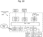
- FIG. 10 A hardware description of a computer/device (e.g., the image processing device 1000) according to exemplary embodiments, or any other embodiment, which is used to encode and/or decode video is described with reference to Fig. 10 .
- the image processing device 1000 includes a CPU 1002 which performs one or more of the processes described above.
- the process data and instructions may be stored in memory 1004, which may be transitory, non-transitory, or a combination of the two.
- the video (data) to be encoded/decoded can original from any source such as an external memory, a network 1006, or other location/device.
- These processes and instructions may also be stored on a storage medium disk 1008 such as a hard drive (HDD) or portable storage medium or may be stored remotely.
- HDD hard drive
- the claimed advancements are not limited by the form of the computer-readable media on which the instructions of the inventive process are stored.
- the instructions may be stored on CDs, DVDs, in FLASH memory, RAM, ROM, PROM, EPROM, EEPROM, hard disk or any other information processing device with which the image processing device 1000 communicates, such as an image processing device or computer.
- claimed advancements may be provided as a utility application, background daemon, or component of an operating system, or combination thereof, executing in conjunction with CPU 1002 and an operating system such as Microsoft Windows, UNIX, Solaris, LINUX, Apple MAC-OS and other suitable operating system.
- an operating system such as Microsoft Windows, UNIX, Solaris, LINUX, Apple MAC-OS and other suitable operating system.
- the image processing device 1000 may be a general-purpose computer or a particular, special-purpose machine. In one embodiment, the image processing device 1000 becomes a particular, special-purpose machine when the processor 1002 is programmed to perform network performance testing.
- the image processing device may be implemented as an encoder, a decoder, or a device which both encodes and decodes images.
- the image processing device can be implemented in a mobile phone, a laptop, a tablet, a general purpose computer, a set-top box, a video decoding device such as an Amazon Fire TV Stick or device, a Roku device, a television, a video monitor, a still camera, a video camera, a scanner, a multifunction printer, an automobile display, or any desired device.
- CPU 1002 may be implemented on an FPGA, ASIC, PLD or using discrete logic circuits, as one of ordinary skill in the art would recognize. Further, CPU 1002 may be implemented as multiple processors cooperatively working in parallel to perform the instructions of the inventive processes described above.
- the image processing device 1000 in Fig. 10 also includes a network controller 1010, such as an Intel Ethernet PRO network interface card from Intel Corporation of America, for interfacing with network 1006.
- the network 1006 can be a public network, such as the Internet, or a private network such as an LAN or WAN network, or any combination thereof and can also include PSTN or ISDN sub-networks.
- the network 1006 can also be wired, such as an Ethernet network, or can be wireless such as a cellular network including EDGE, 3G and 4G wireless cellular systems.
- the wireless network can also be WiFi, Bluetooth, or any other wireless form of communication that is known.
- the image processing device 1000 further includes a display controller 1012, such as a graphics card or graphics adaptor for interfacing with display 1014, such as a monitor.
- a general purpose I/O interface 1016 interfaces with a keyboard and/or mouse 1018 as well as a touch screen panel 1020 on or separate from display 1014.
- General purpose I/O interface also connects to a variety of peripherals 1022 including printers and scanners.
- a sound controller 1024 is also provided in the image processing device 1000 to interface with speakers/microphone 1026 thereby providing sounds and/or music.
- the general-purpose storage controller 1028 connects the storage medium disk 1008 with communication bus 1030, which may be an ISA, EISA, VESA, PCI, or similar, for interconnecting all of the components of the image processing device 1000.
- communication bus 1030 may be an ISA, EISA, VESA, PCI, or similar, for interconnecting all of the components of the image processing device 1000.
- a description of the general features and functionality of the display 1014, keyboard and/or mouse 1018, as well as the display controller 1012, storage controller 1028, network controller 1010, sound controller 1024, and general purpose I/O interface 1016 is omitted herein for brevity.
- circuitry configured to perform features described herein may be implemented in multiple circuit units (e.g., chips), or the features may be combined in circuitry on a single chipset.
- any hardware and/or software capable of implementing any of the above embodiments, or any other embodiment can be used instead of, or in addition to, what is disclosed above.
- the functions and features described herein may also be executed by various distributed components of a system.
- one or more processors may execute these system functions, wherein the processors are distributed across multiple components communicating in a network.
- the distributed components may include one or more client and server machines, which may share processing, in addition to various human interface and communication devices (e.g., display monitors, smart phones, tablets, personal digital assistants (PDAs)).
- the network may be a private network, such as a LAN or WAN, or may be a public network, such as the Internet. Input to the system may be received via direct user input and received remotely either in real-time or as a batch process. Additionally, some implementations may be performed on modules or hardware not identical to those described. Accordingly, other implementations are within the scope that may be claimed.
Landscapes
- Engineering & Computer Science (AREA)
- Multimedia (AREA)
- Signal Processing (AREA)
- Physics & Mathematics (AREA)
- Discrete Mathematics (AREA)
- General Physics & Mathematics (AREA)
- Compression Or Coding Systems Of Tv Signals (AREA)
Applications Claiming Priority (4)
| Application Number | Priority Date | Filing Date | Title |
|---|---|---|---|
| US201862757004P | 2018-11-07 | 2018-11-07 | |
| US201862769875P | 2018-11-20 | 2018-11-20 | |
| US201962792195P | 2019-01-14 | 2019-01-14 | |
| US16/665,484 US11212521B2 (en) | 2018-11-07 | 2019-10-28 | Control of memory bandwidth consumption of affine mode in versatile video coding |
Publications (1)
| Publication Number | Publication Date |
|---|---|
| EP3651465A1 true EP3651465A1 (fr) | 2020-05-13 |
Family
ID=68581142
Family Applications (1)
| Application Number | Title | Priority Date | Filing Date |
|---|---|---|---|
| EP19207520.8A Pending EP3651465A1 (fr) | 2018-11-07 | 2019-11-06 | Contrôle de la consommation de largeur de bande de mémoire de mode affine en codage vidéo polyvalent |
Country Status (3)
| Country | Link |
|---|---|
| US (3) | US11212521B2 (fr) |
| EP (1) | EP3651465A1 (fr) |
| CN (1) | CN111163321B (fr) |
Cited By (1)
| Publication number | Priority date | Publication date | Assignee | Title |
|---|---|---|---|---|
| EP3766247A4 (fr) * | 2018-04-02 | 2022-01-19 | MediaTek Inc. | Procédés et appareils de traitement vidéo pour une compensation de mouvement de sous-bloc dans des systèmes de codage vidéo |
Families Citing this family (2)
| Publication number | Priority date | Publication date | Assignee | Title |
|---|---|---|---|---|
| US10904550B2 (en) * | 2019-01-12 | 2021-01-26 | Tencent America LLC | Method and apparatus for video coding |
| US11792423B2 (en) * | 2019-11-22 | 2023-10-17 | Qualcomm Incorporated | Early termination of motion vector refinement process in video coding |
Citations (1)
| Publication number | Priority date | Publication date | Assignee | Title |
|---|---|---|---|---|
| WO2019139309A1 (fr) * | 2018-01-15 | 2019-07-18 | 삼성전자 주식회사 | Procédé de codage et appareil correspondant, et procédé de décodage et appareil correspondant |
Family Cites Families (42)
| Publication number | Priority date | Publication date | Assignee | Title |
|---|---|---|---|---|
| US6037988A (en) * | 1996-03-22 | 2000-03-14 | Microsoft Corp | Method for generating sprites for object-based coding sytems using masks and rounding average |
| US6553069B1 (en) * | 1999-06-17 | 2003-04-22 | Samsung Electronics Co., Ltd. | Digital image segmenting method and device |
| US7210099B2 (en) * | 2000-06-12 | 2007-04-24 | Softview Llc | Resolution independent vector display of internet content |
| WO2004114063A2 (fr) * | 2003-06-13 | 2004-12-29 | Georgia Tech Research Corporation | Reconstruction des donnees a l'aide de techniques d'interpolation directionnelle |
| KR20050078706A (ko) * | 2004-01-31 | 2005-08-08 | 삼성전자주식회사 | 메모리 액세스 방법 및 메모리 액세스 장치 |
| US8238429B2 (en) * | 2005-12-02 | 2012-08-07 | Texas Instruments Incorporated | Statistically cycle optimized bounding box for high definition video decoding |
| EP1977395B1 (fr) * | 2006-01-27 | 2018-10-24 | Imax Corporation | Procedes et systemes pour le rematriçage numerique de films bi- et tridimensionnels pour une presentation avec une qualite visuelle amelioree |
| US8073196B2 (en) * | 2006-10-16 | 2011-12-06 | University Of Southern California | Detection and tracking of moving objects from a moving platform in presence of strong parallax |
| US7924317B2 (en) * | 2008-03-12 | 2011-04-12 | Aptina Imaging Corporation | Method and apparatus for reducing motion blur in digital images |
| US9355293B2 (en) * | 2008-12-22 | 2016-05-31 | Canon Kabushiki Kaisha | Code detection and decoding system |
| US9197736B2 (en) * | 2009-12-31 | 2015-11-24 | Digimarc Corporation | Intuitive computing methods and systems |
| US8121618B2 (en) * | 2009-10-28 | 2012-02-21 | Digimarc Corporation | Intuitive computing methods and systems |
| US8175617B2 (en) * | 2009-10-28 | 2012-05-08 | Digimarc Corporation | Sensor-based mobile search, related methods and systems |
| US8660355B2 (en) * | 2010-03-19 | 2014-02-25 | Digimarc Corporation | Methods and systems for determining image processing operations relevant to particular imagery |
| KR101066068B1 (ko) * | 2011-03-22 | 2011-09-20 | (주)유디피 | 듀얼 카메라를 이용한 영상 감시 장치 및 방법 |
| US20140092439A1 (en) * | 2012-09-28 | 2014-04-03 | Scott A. Krig | Encoding images using a 3d mesh of polygons and corresponding textures |
| US9274742B2 (en) * | 2012-10-25 | 2016-03-01 | PixiOnCloud, Inc. | Visual-symbolic control of remote devices having display-based user interfaces |
| KR102121558B1 (ko) * | 2013-03-15 | 2020-06-10 | 삼성전자주식회사 | 비디오 이미지의 안정화 방법, 후처리 장치 및 이를 포함하는 비디오 디코더 |
| US9734589B2 (en) * | 2014-07-23 | 2017-08-15 | Kineticor, Inc. | Systems, devices, and methods for tracking and compensating for patient motion during a medical imaging scan |
| CN112929659B (zh) * | 2015-10-13 | 2023-12-26 | 三星电子株式会社 | 用于对图像进行编码或解码的方法和设备 |
| US20190158870A1 (en) * | 2016-01-07 | 2019-05-23 | Mediatek Inc. | Method and apparatus for affine merge mode prediction for video coding system |
| US10798403B2 (en) * | 2016-01-29 | 2020-10-06 | Sharp Kabushiki Kaisha | Prediction image generation device, video decoding device, and video coding device |
| WO2017147765A1 (fr) * | 2016-03-01 | 2017-09-08 | Mediatek Inc. | Procédés de compensation de mouvement affine |
| EP3414900B1 (fr) * | 2016-03-15 | 2025-08-06 | HFI Innovation Inc. | Procédé et appareil de codage vidéo avec compensation de mouvement affine |
| KR102638991B1 (ko) * | 2016-03-24 | 2024-02-21 | 엘지전자 주식회사 | 비디오 코딩 시스템에서 인터 예측 방법 및 장치 |
| US11095898B2 (en) * | 2016-03-28 | 2021-08-17 | Lg Electronics Inc. | Inter-prediction mode based image processing method, and apparatus therefor |
| EP3457696B1 (fr) * | 2016-05-13 | 2026-03-04 | Sharp Kabushiki Kaisha | Dispositif de génération d'image prédite, dispositif de décodage de vidéo et dispositif de codage de vidéo |
| US10560712B2 (en) * | 2016-05-16 | 2020-02-11 | Qualcomm Incorporated | Affine motion prediction for video coding |
| US20180047193A1 (en) * | 2016-08-15 | 2018-02-15 | Qualcomm Incorporated | Adaptive bounding box merge method in blob analysis for video analytics |
| WO2018049594A1 (fr) * | 2016-09-14 | 2018-03-22 | Mediatek Inc. | Procédés de décision de codeur pour une structure d'arbre binaire et d'arbre quaternaire |
| US10631002B2 (en) * | 2016-09-30 | 2020-04-21 | Qualcomm Incorporated | Frame rate up-conversion coding mode |
| US10448010B2 (en) * | 2016-10-05 | 2019-10-15 | Qualcomm Incorporated | Motion vector prediction for affine motion models in video coding |
| US20190273943A1 (en) * | 2016-10-10 | 2019-09-05 | Sharp Kabushiki Kaisha | Systems and methods for performing motion compensation for coding of video data |
| US10681370B2 (en) * | 2016-12-29 | 2020-06-09 | Qualcomm Incorporated | Motion vector generation for affine motion model for video coding |
| WO2018128379A1 (fr) * | 2017-01-03 | 2018-07-12 | 엘지전자(주) | Procédé et dispositif de traitement de signal vidéo par prédiction affine |
| WO2018128380A1 (fr) * | 2017-01-03 | 2018-07-12 | 엘지전자(주) | Procédé et dispositif de traitement de signal vidéo par prédiction affine |
| JP7036628B2 (ja) * | 2017-03-10 | 2022-03-15 | パナソニック インテレクチュアル プロパティ コーポレーション オブ アメリカ | 符号化装置、復号装置、符号化方法及び復号方法 |
| US10701390B2 (en) * | 2017-03-14 | 2020-06-30 | Qualcomm Incorporated | Affine motion information derivation |
| US10553091B2 (en) * | 2017-03-31 | 2020-02-04 | Qualcomm Incorporated | Methods and systems for shape adaptation for merged objects in video analytics |
| US10602180B2 (en) * | 2017-06-13 | 2020-03-24 | Qualcomm Incorporated | Motion vector prediction |
| JP2019017066A (ja) * | 2017-07-03 | 2019-01-31 | パナソニック インテレクチュアル プロパティ コーポレーション オブ アメリカPanasonic Intellectual Property Corporation of America | 符号化装置、復号装置、符号化方法及び復号方法 |
| US10510157B2 (en) * | 2017-10-28 | 2019-12-17 | Altumview Systems Inc. | Method and apparatus for real-time face-tracking and face-pose-selection on embedded vision systems |
-
2019
- 2019-10-28 US US16/665,484 patent/US11212521B2/en active Active
- 2019-11-06 EP EP19207520.8A patent/EP3651465A1/fr active Pending
- 2019-11-07 CN CN201911083188.XA patent/CN111163321B/zh active Active
-
2021
- 2021-12-23 US US17/561,665 patent/US12261998B2/en active Active
-
2025
- 2025-03-25 US US19/090,312 patent/US20250373784A1/en active Pending
Patent Citations (1)
| Publication number | Priority date | Publication date | Assignee | Title |
|---|---|---|---|---|
| WO2019139309A1 (fr) * | 2018-01-15 | 2019-07-18 | 삼성전자 주식회사 | Procédé de codage et appareil correspondant, et procédé de décodage et appareil correspondant |
Non-Patent Citations (3)
| Title |
|---|
| HE (INTERDIGITAL) Y ET AL: "Description of Core Experiment 2 (CE2): Sub-block based motion prediction", no. JVET-L1022, 3 November 2018 (2018-11-03), XP030198596, Retrieved from the Internet <URL:http://phenix.int-evry.fr/jvet/doc_end_user/documents/12_Macao/wg11/JVET-L1022-v2.zip JVET-L1022-v2-clean.docx> [retrieved on 20181103] * |
| T-D CHUANG ET AL: "CE9.2.1: Bilateral matching merge mode", no. JVET-K0254, 10 July 2018 (2018-07-10), XP030199311, Retrieved from the Internet <URL:http://phenix.int-evry.fr/jvet/doc_end_user/documents/11_Ljubljana/wg11/JVET-K0254-v2.zip JVET-K0254-v1.docx> [retrieved on 20180710] * |
| ZHOU (BROADCOM) M: "CE2-related: A restriction on memory bandwidth consumption of affine mode", no. m45303, 28 December 2018 (2018-12-28), XP030197660, Retrieved from the Internet <URL:http://phenix.int-evry.fr/mpeg/doc_end_user/documents/125_Marrakech/wg11/m45303-JVET-M0049-v1-JVET-M0049-v1.zip JVET-M0049-v1.docx> [retrieved on 20181228] * |
Cited By (5)
| Publication number | Priority date | Publication date | Assignee | Title |
|---|---|---|---|---|
| EP3766247A4 (fr) * | 2018-04-02 | 2022-01-19 | MediaTek Inc. | Procédés et appareils de traitement vidéo pour une compensation de mouvement de sous-bloc dans des systèmes de codage vidéo |
| US11381834B2 (en) | 2018-04-02 | 2022-07-05 | Hfi Innovation Inc. | Video processing methods and apparatuses for sub-block motion compensation in video coding systems |
| US11956462B2 (en) | 2018-04-02 | 2024-04-09 | Hfi Innovation Inc. | Video processing methods and apparatuses for sub-block motion compensation in video coding systems |
| EP4604535A3 (fr) * | 2018-04-02 | 2025-11-05 | HFI Innovation Inc. | Procédés et appareils de traitement vidéo pour la compensation de mouvement de sous-bloc dans des systèmes de codage vidéo |
| US12501066B2 (en) | 2018-04-02 | 2025-12-16 | Hfi Innovation Inc. | Video processing methods and apparatuses for sub-block motion compensation in video coding systems |
Also Published As
| Publication number | Publication date |
|---|---|
| US11212521B2 (en) | 2021-12-28 |
| CN111163321A (zh) | 2020-05-15 |
| CN111163321B (zh) | 2022-11-29 |
| US20220232204A1 (en) | 2022-07-21 |
| US20200145650A1 (en) | 2020-05-07 |
| US12261998B2 (en) | 2025-03-25 |
| US20250373784A1 (en) | 2025-12-04 |
Similar Documents
| Publication | Publication Date | Title |
|---|---|---|
| US12413770B2 (en) | Methods and apparatus of motion vector rounding, clipping and storage for inter prediction | |
| US20250373784A1 (en) | Control of memory bandwidth consumption of affine mode in versatile video coding | |
| JP7717201B2 (ja) | 三角形予測のためのビデオ符号化復号化の方法及び装置 | |
| JP4685636B2 (ja) | 復号化装置、符号化装置、補間フレーム生成システム、集積回路装置、復号化プログラムおよび符号化プログラム | |
| WO2021188598A1 (fr) | Procédés et dispositifs pour un affinement de prédiction à compensation de mouvement affine | |
| JP7411023B2 (ja) | ビデオ符号化におけるデコーダ側動きベクトル補正のための方法および装置 | |
| US12470733B2 (en) | Overlapped block motion compensation for inter prediction | |
| CN116491120A (zh) | 用于仿射运动补偿预测细化的方法和装置 | |
| US20240098290A1 (en) | Methods and devices for overlapped block motion compensation for inter prediction | |
| US12356001B2 (en) | Methods and apparatus of motion vector rounding, clipping and storage for inter prediction | |
| WO2022032028A1 (fr) | Procédés et appareils pour le raffinement de prédictions affines compensées en mouvement | |
| CN114342390B (zh) | 用于仿射运动补偿的预测细化的方法和装置 | |
| JP2010074347A (ja) | 動画符号化装置および動画符号化方法 |
Legal Events
| Date | Code | Title | Description |
|---|---|---|---|
| PUAI | Public reference made under article 153(3) epc to a published international application that has entered the european phase |
Free format text: ORIGINAL CODE: 0009012 |
|
| STAA | Information on the status of an ep patent application or granted ep patent |
Free format text: STATUS: THE APPLICATION HAS BEEN PUBLISHED |
|
| AK | Designated contracting states |
Kind code of ref document: A1 Designated state(s): AL AT BE BG CH CY CZ DE DK EE ES FI FR GB GR HR HU IE IS IT LI LT LU LV MC MK MT NL NO PL PT RO RS SE SI SK SM TR |
|
| AX | Request for extension of the european patent |
Extension state: BA ME |
|
| STAA | Information on the status of an ep patent application or granted ep patent |
Free format text: STATUS: REQUEST FOR EXAMINATION WAS MADE |
|
| 17P | Request for examination filed |
Effective date: 20201113 |
|
| RBV | Designated contracting states (corrected) |
Designated state(s): AL AT BE BG CH CY CZ DE DK EE ES FI FR GB GR HR HU IE IS IT LI LT LU LV MC MK MT NL NO PL PT RO RS SE SI SK SM TR |
|
| STAA | Information on the status of an ep patent application or granted ep patent |
Free format text: STATUS: EXAMINATION IS IN PROGRESS |
|
| 17Q | First examination report despatched |
Effective date: 20230717 |