EP3651919B1 - Méthode de fonctionnement d'un appareil de coulée pour coulée sous pression - Google Patents
Méthode de fonctionnement d'un appareil de coulée pour coulée sous pression Download PDFInfo
- Publication number
- EP3651919B1 EP3651919B1 EP18759020.3A EP18759020A EP3651919B1 EP 3651919 B1 EP3651919 B1 EP 3651919B1 EP 18759020 A EP18759020 A EP 18759020A EP 3651919 B1 EP3651919 B1 EP 3651919B1
- Authority
- EP
- European Patent Office
- Prior art keywords
- furnace
- receiving space
- individual valves
- pressure
- valve block
- Prior art date
- Legal status (The legal status is an assumption and is not a legal conclusion. Google has not performed a legal analysis and makes no representation as to the accuracy of the status listed.)
- Active
Links
Images
Classifications
-
- B—PERFORMING OPERATIONS; TRANSPORTING
- B22—CASTING; POWDER METALLURGY
- B22D—CASTING OF METALS; CASTING OF OTHER SUBSTANCES BY THE SAME PROCESSES OR DEVICES
- B22D18/00—Pressure casting; Vacuum casting
- B22D18/04—Low pressure casting, i.e. making use of pressures up to a few bars to fill the mould
-
- B—PERFORMING OPERATIONS; TRANSPORTING
- B22—CASTING; POWDER METALLURGY
- B22D—CASTING OF METALS; CASTING OF OTHER SUBSTANCES BY THE SAME PROCESSES OR DEVICES
- B22D17/00—Pressure die casting or injection die casting, i.e. casting in which the metal is forced into a mould under high pressure
- B22D17/20—Accessories: Details
- B22D17/28—Melting pots
-
- B—PERFORMING OPERATIONS; TRANSPORTING
- B22—CASTING; POWDER METALLURGY
- B22D—CASTING OF METALS; CASTING OF OTHER SUBSTANCES BY THE SAME PROCESSES OR DEVICES
- B22D17/00—Pressure die casting or injection die casting, i.e. casting in which the metal is forced into a mould under high pressure
- B22D17/20—Accessories: Details
- B22D17/30—Accessories for supplying molten metal, e.g. in rations
-
- B—PERFORMING OPERATIONS; TRANSPORTING
- B22—CASTING; POWDER METALLURGY
- B22D—CASTING OF METALS; CASTING OF OTHER SUBSTANCES BY THE SAME PROCESSES OR DEVICES
- B22D17/00—Pressure die casting or injection die casting, i.e. casting in which the metal is forced into a mould under high pressure
- B22D17/20—Accessories: Details
- B22D17/32—Controlling equipment
-
- B—PERFORMING OPERATIONS; TRANSPORTING
- B22—CASTING; POWDER METALLURGY
- B22D—CASTING OF METALS; CASTING OF OTHER SUBSTANCES BY THE SAME PROCESSES OR DEVICES
- B22D18/00—Pressure casting; Vacuum casting
-
- B—PERFORMING OPERATIONS; TRANSPORTING
- B22—CASTING; POWDER METALLURGY
- B22D—CASTING OF METALS; CASTING OF OTHER SUBSTANCES BY THE SAME PROCESSES OR DEVICES
- B22D18/00—Pressure casting; Vacuum casting
- B22D18/08—Controlling, supervising, e.g. for safety reasons
-
- B—PERFORMING OPERATIONS; TRANSPORTING
- B22—CASTING; POWDER METALLURGY
- B22D—CASTING OF METALS; CASTING OF OTHER SUBSTANCES BY THE SAME PROCESSES OR DEVICES
- B22D27/00—Treating the metal in the mould while it is molten or ductile ; Pressure or vacuum casting
- B22D27/09—Treating the metal in the mould while it is molten or ductile ; Pressure or vacuum casting by using pressure
- B22D27/13—Treating the metal in the mould while it is molten or ductile ; Pressure or vacuum casting by using pressure making use of gas pressure
-
- B—PERFORMING OPERATIONS; TRANSPORTING
- B22—CASTING; POWDER METALLURGY
- B22D—CASTING OF METALS; CASTING OF OTHER SUBSTANCES BY THE SAME PROCESSES OR DEVICES
- B22D39/00—Equipment for supplying molten metal in rations
- B22D39/06—Equipment for supplying molten metal in rations having means for controlling the amount of molten metal by controlling the pressure above the molten metal
Definitions
- the invention relates to a method for operating a casting device for casting under pressure, in particular a counter-pressure chill casting device or low-pressure chill casting device.
- Such casting devices in particular for casting under a pressure generated by a gas phase, are used in foundry technology, in particular for the production of castings with high physical and mechanical parameters, in particular from light metal alloys.
- a system for casting under pressure with at least one casting device comprising a lower hermetically sealable chamber and an upper hermetically sealable chamber is known.
- the chambers are separated from each other by an intermediate plate or platen, the lower chamber having a furnace with melt, and in the upper chamber an approximately horizontally divided casting mold is arranged, which consists of a lower casting mold half and an upper casting mold half.
- the furnace with the melt and the casting mold are connected to one another via at least one riser pipe mounted on the intermediate plate or the mold mounting plate.
- a die-casting process is known in which three compressed air-controlled valves are used to introduce compressed air into the furnace.
- the casting process is divided into three phases. In the first phase, the molten metal is raised in the riser pipe. In the second phase, the mold is filled with metal. In the third phase, pressure is applied to the filled casting mold.
- Each of the three compressed air-controlled valves is provided for introducing compressed air into the furnace in one of the three phases.
- a die-casting process is known in which, under the action of a pressure difference, a melt is conveyed from a furnace located in a hermetically sealed pantry through a pouring tube into the cavity of a casting mold, the casting mold being arranged in another hermetically sealed equalizing chamber. In the compensation chamber, the casting solidifies at the temperature and pressure there. The finished casting is then removed from the casting mold and a new casting cycle can be carried out.
- the counter pressure chill casting process known to the person skilled in the art is a further development of the so-called low pressure casting process and from various publications, for example the EP 0 221 196 B1 , the EP 0 564 774 B1 or the DE 3422 121 A1 known.
- pressurized gas is applied not only to the casting furnace, but also to the mold or casting mold.
- the US 2014/294664 A1 discloses a casting furnace which can be pressurized by means of a small and a large valve.
- the actual casting process takes place both in the low-pressure casting process and in the counter-pressure die casting process with the aid of a riser pipe through which the melt is conveyed upwards into the die.
- the pressurization of the melt in the furnace for conveying the melt up into the mold is brought about in the counter-pressure mold casting process by a pressure difference in that the gas pressure in the mold is lowered somewhat. This creates an overpressure in the casting furnace that is sufficient for the melt to rise into the mold.
- the disadvantage of the known systems is that the casting process can only be controlled very imprecisely and thus the workpiece quality of the cast workpiece can suffer losses.
- the object of the present invention was to overcome the disadvantages of the prior art and to provide a method by means of which high-quality workpieces can be cast.
- the advantage of the casting device is that the air flow rate can be set variably by means of the at least four individual valves and the casting process can thus be precisely controlled.
- the timing of the casting process can also be precisely controlled.
- the pressure sensor serves as a monitoring variable for the control cycle. Because the individual valves can be opened individually or simultaneously, independently of one another, and also have different characteristics, the air flow rate can be set almost steplessly or, ideally, even completely steplessly, by selectively switching the individual valves.
- the individual valves are designed in the form of slide valves.
- the advantage here is that such slide valves have an exact switching behavior and thus the air flow rate can be precisely adjusted using slide valves.
- the individual valves are designed in the form of digitally controlled valves.
- digitally controlled valves can be controlled directly by the electronic digital computer and can therefore have very short switching times or response times.
- At least one further pressure sensor which is coupled to the electronic digital computer, is arranged on the compressed air supply side of the valve block.
- This measure can also take into account the inlet pressure present at the valve block. The flow behavior of the individual valves can thus be predicted, which simplifies the regulation of the amount of air supplied.
- a temperature sensor is arranged in the receiving space of the furnace, which is coupled to the electronic digital computer.
- This measure can take into account the temperature in the receiving space of the furnace and thus also the thermal expansion of the air which is introduced into the receiving space of the furnace.
- the casting mold comprises a lower casting mold part and an upper casting mold part, the two casting mold parts forming a mold cavity in the joined state and a supporting structure on which the upper casting mold part is arranged, the upper casting mold part being relatively by means of the supporting structure is displaceable to the lower mold part.
- the advantage here is that by means of this measure, the two mold parts can easily be moved towards one another.
- the advantage of the method according to the invention is that, by regulating the individual valves of the valve block on the basis of the mathematical model of the casting device, the individual casting steps can be carried out with high precision and precisely timed. This makes it possible to manufacture cast workpieces of extremely high quality.
- the compressed air leakage from the receiving space of the furnace is taken into account in the mathematical model of the casting device.
- the advantage here is that this can improve the accuracy of the compressed air regulation.
- the compressed air leakage is determined in that the receiving space of the furnace is pressurized and that the individual valves of the valve block are then closed and the pressure drop is observed over time.
- the currently present compressed air leakage can be determined at periodic time intervals and thus a highly accurate model of the casting device can be provided.
- the geometric dimensions of the receiving space of the furnace are stored in the mathematical model of the casting device.
- the advantage here is that on the basis of the knowledge of the geometric dimensions of the receiving space of the furnace, the relationship between the fill level of the melt in the receiving space and the area freely accessible for compressed air can be taken into account.
- the flow behavior of the individual valves is stored in the mathematical model of the casting device as a function of the pressure in the receiving space of the furnace and the pressure on the compressed air supply side of the valve block.
- the thermal expansion of the air in the receiving space of the furnace is taken into account in the mathematical model of the casting device, this expansion being based on the thermal expansion coefficient of the supplied air, the geometric dimensions of the receiving space of the furnace, the fill quantity of melt in the receiving space of the furnace, the temperature of the air supplied and the temperature in the receiving space of the furnace is calculated.
- This measure can improve the accuracy of the casting process and thereby the workpiece quality.
- the filling state of the melt in the receiving space is taken into account in the mathematical model of the casting device.
- the filling state of the melt in the receiving space is calculated after a new filling process of the receiving space in that the receiving space is depressurized, then a certain volume flow of air is admitted into the receiving space of the furnace by means of the individual valves of the valve block and the free volume and, derived therefrom, the volume filled with melt in the receiving space of the furnace is calculated over the course of the pressure increase in the receiving space of the furnace.
- the advantage here is that the fill state of the melt in the receiving space does not have to be determined by further sensors, which have a complicated structure and are also prone to errors.
- the individual valves of the valve block for regulating the flow rate of the air are only brought into the open state or into the closed state, and therefore assume exclusively binary states.
- This measure means that the flow rates of compressed air in the individual valves are exactly known. This means that the current flow rate of compressed air can be precisely controlled at any time.
- the individual valves are subjected to an increased overvoltage during the opening process in order to shorten the switching time and then to be kept in the open state under the application of a lower switching voltage.
- the advantage here is that the switching times of the individual valves can be shortened by this measure and thus a highly precise control is made possible.
- the individual valves of the valve block are controlled in such a way that the leakage of the compressed air from the furnace is compensated and thus the pressure in the receiving space of the furnace is consistently high and the melt in the riser pipe does not sink.
- This measure means that the melt in the riser pipe does not first have to be raised again when casting a new cast workpiece, but that the actual casting process can be started immediately. As a result, the casting time can be reduced and the efficiency of the casting process or the casting system can be increased significantly.
- the individual valves of the valve block are controlled in such a way that one of the individual valves is opened while another of the individual valves is closed and thus the time behavior of the air flow rates in the individual valves during the opening process and during the closing process is used to achieve a certain total flow rate of the To reach the valve block.
- the advantage here is that by means of this measure, the flow rate of the valve block can be set with a finer gradation than the proportion of an individual valve in the total flow rate. It may be necessary here for the individual valves to be switched continuously.
- the individual valves of the valve block viewed over a certain period of time, are opened or closed again so often that the integrated open time of a valve determines the flow rate over this period of time.
- this measure enables pulse width modulation to be implemented in the individual valves of the valve block.
- the air flow rate when fully open and at a certain viscosity of the air is mainly influenced by the flow cross section. Furthermore, the air flow rate can be influenced by the geometry of the individual valve. Further characteristics are the opening behavior of the individual valve and the closing behavior of the individual valve. As opening behavior and closing behavior of the individual valve describes the behavior of the air flow rates over time during the opening process and during the closing process.
- a valve block is a collection of several individual valves which are suitable for allowing compressed air to flow into the receiving space of the furnace parallel to one another.
- the individual valves are preferably structurally coupled to one another in the valve block. However, it is also conceivable and to be regarded as equivalent if the individual valves are not structurally coupled to one another.
- As a valve block in its broadest definition the presence of several individual valves is understood, which are suitable for allowing compressed air to flow into the receiving space of the furnace parallel to one another.
- the intermediate plate can also be referred to as a mold mounting plate, since it serves to hold and fasten the lower molded part.
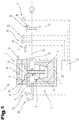
- Fig. 1 shows a schematic representation of an exemplary embodiment of a casting device 1.
- the casting device 1 is in particular a low-pressure chill casting device or a counter-pressure chill casting device.
- the casting device 1 comprises a furnace 2 in which a receiving space 3 for receiving melt 4 is formed.
- a container 5, in which the melt 4 is received is arranged in the furnace 2.
- the container 5 can be formed from a ceramic material which has a high temperature resistance.
- the furnace 2 can in particular serve to keep the melt 4 at a high temperature level so that it remains in the molten state.
- an intermediate plate 6 is formed which delimits the furnace 2 at the top.
- the intermediate plate 6 can either be designed as a separate component or as an integral component of the furnace 2.
- the two mold parts 8, 9 form a mold cavity 10 which serves to receive the melt 4 and to shape the cast workpiece.
- the casting mold 7 can be designed, for example, in the form of a permanent mold, which is suitable for casting several thousand workpieces.
- the casting mold 7 is designed as a lost casting mold, for example made from a sand material, and thus only serves to cast a single workpiece.
- a riser pipe 11 is formed which protrudes into the receiving space 3 of the furnace 2 and penetrates the intermediate plate 6.
- the lower mold part 8 can connect directly to the riser pipe 11 and have a melt inlet 12 into which the riser pipe 11 opens.
- a support structure 13 is shown in a greatly simplified manner, which can be coupled to the upper mold part 9 and can serve to move the upper mold part 9 relative to the lower mold part 8.
- the furnace 2 also has a compressed air supply opening 14 through which compressed air can be introduced into the receiving space 3 of the furnace 2. By pressurizing the receiving space 3 of the furnace 2 with compressed air, the melt 4 in the riser pipe 11 is pressed into the mold cavity 10.
- a compressed air supply line 15 can be provided which is connected to the compressed air supply opening 14.
- a discharge valve 16, which is used to discharge the compressed air from the receiving space 3 of the furnace 2, can be coupled to the compressed air supply line 15 in a branch.
- the drain valve 16 is coupled to the furnace 2 at its own connection.
- a valve block 17, which has a plurality of individual valves 18, can be coupled to the compressed air supply line 15.
- the individual valves 18 of the valve block 17 are connected in parallel to one another.
- the individual individual valves 18 formed in the valve block 17 have a different flow rate from one another, as a result of which different flow rates can be set in the valve block 17 by selective switching of the individual valves 18.
- some of the individual valves 18 have the same characteristic data and that some of the individual valves 18 have mutually different characteristic data.
- valve block 17 has a total of thirteen individual valves 18, the individual valves 18 having a total of six different characteristic data.
- an electronic digital computer 19 is designed, which is used to control the individual valves 18 or the discharge valve 16.
- a pressure sensor 20 is coupled to the electronic digital computer 19, which sensor detects the internal pressure prevailing in the receiving space 3 of the furnace 2.
- a further pressure sensor 21 can be formed which detects the inlet pressure of the valve block 17.
- Another pressure sensor 22, which includes the output pressure of the valve block 17, can optionally be formed.
- This further pressure sensor 22 and the pressure sensor 20 are located in the same flow space, as a result of which the further pressure sensor 22 can also be omitted.
- a temperature sensor 23 can be formed by means of which a temperature inside the furnace 2 can be detected.
- a further temperature sensor 24 can be formed, by means of which the temperature of the compressed air flowing into the furnace 2 can be detected.
- a method for producing a cast workpiece or a method for operating the casting device 1 is described below.
- the furnace 2 is pressurized and then the compressed air supply is closed.
- the leakage amount of compressed air in the furnace 2 can be determined from the time profile of the pressure drop inside the furnace 2. This amount of leakage is stored in the mathematical model of the furnace and is subsequently used as a variable for regulating the compressed air supply to the furnace 2.
- the riser pipe 11 can be closed either by the melt and / or by an additional closure.
- the amount of leakage from furnace 2 can be determined while a container 5 with melt 4 is arranged in furnace 2 or even while no container 5 with melt 4 is arranged in furnace 2.
- the temporal mass balance of the amount of air in the furnace can be precisely determined or controlled.
- the container 5 is filled with melt 4 or a container 5 filled with melt 4 is introduced into the furnace 2.
- the amount of melt 4 in the container 5 can be determined, for example, via weight sensors 26.
- the amount of melt 4 in the container 5 is determined by applying pressure to the interior of the furnace 2, as a result of which the melt 4 rises in the riser pipe 11.
- the temperature and the amount of air introduced into the furnace 2 can be used to calculate the displacement of the melt 4 and from this the amount of melt 4 in the container 5 can be calculated.
- the actual casting process can then be started in a further process step.
- the casting speed can be regulated by regulating the internal pressure in the furnace 2 and thus by adjusting the amount of air supplied.
- the internal pressure in the furnace 2 can be kept constant, the leakage of compressed air from the furnace 2 being compensated for by the compressed air supplied.
- the shrinkage of the melt 4 in the mold cavity 10 during the cooling and solidification process can be compensated for.
- the pressure in the furnace 2 can then be lowered and the casting mold 7 can be opened to remove the cast workpiece.
- the internal pressure in the furnace 2 can be maintained at such a level that the melt 4 remains in the riser pipe 11 while the cast workpiece is being removed.
- the casting mold 7 can then be closed and a further casting process can be started. By calculating the material loss of melt 4 into the cast workpiece, the amount of melt 4 in the container 5 can be determined at any point in time.
- the individual valves 18 of the valve block 17 are opened or closed accordingly in a chronological sequence.
- an induction device 25 is formed, which is arranged around the riser pipe.
- the induction device 25 By means of the induction device 25, a force can be exerted on the melt 4 located in the riser pipe 11 in the flow direction or against the flow direction of the melt 4.
- the conveyance of the melt 4 from the receiving space 3 into the mold cavity 10 can thus be supported or counteracted by means of the induction device 25.
- this makes it possible to exert a force on the mold 7 when changing the mold To apply melt against the direction of flow, whereby it can be achieved that in spite of the application of pressure to the receiving space 3, the melt does not exit from the riser pipe 11.
- the position of the melt is detected by means of the induction device 25 by measuring the voltage drop across the induction device 25.
- the induction device 25 is preferably designed in the form of a coil which surrounds the riser pipe 11 in a helical manner.
- All information on value ranges in the present description should be understood to include any and all sub-areas, e.g. the information 1 to 10 should be understood to include all sub-areas, starting from the lower limit 1 and the upper limit 10 , ie all sub-ranges begin with a lower limit of 1 or greater and end at an upper limit of 10 or less, for example 1 to 1.7, or 3.2 to 8.1, or 5.5 to 10.
Landscapes
- Engineering & Computer Science (AREA)
- Mechanical Engineering (AREA)
- Molds, Cores, And Manufacturing Methods Thereof (AREA)
Claims (12)
- Procédé de fonctionnement d'un dispositif de coulée (1) pour une coulée sous pression, plu particulièrement un dispositif de coulée à lingotière à contre-pression ou un dispositif de coulée à lingotière à basse pression, comprenant :- un four (2), dans lequel un espace de logement (3) est réalisé pour le logement d'une fonte (4), dans lequel l'espace de logement (3) peut être alimenté en air comprimé ;- un bloc de soupapes (17) pour l'admission régulée d'air comprimé dans l'espace de logement (3) du four (2) ;- un capteur de pression (20), qui est conçu pour la mesure de la pression régnant dans l'espace de logement (3) du four (2) ;- un moule de coulée (7), qui forme une cavité de moule (10) ;- une plaque intermédiaire (6), qui est disposée entre le four (2) et le moule de coulée (7), dans lequel le moule de coulée (7) est fixé à la plaque intermédiaire (6) ;- au moins un tube ascendant (11) au moyen duquel l'espace de logement (3) du four (2) est relié en écoulement avec le moule de coulée (7) ;dans lequel le bloc de soupapes (17) comprend au moins quatre soupapes individuelles (18) qui sont conçus pour laisser entrer, parallèlement entre elles, de l'air comprimé dans l'espace de logement (3) du four (2), dans lequel au moins deux des soupapes individuelles (18) présentent des données caractéristiques différentes entre elles, dans lequel les soupapes individuelles (18) sont couplées avec un calculateur numérique électronique (19), par lequel elles sont contrôlées, dans lequel le calculateur numérique électronique (19) est couplé avec le capteur de pression (20), dans lequel les soupapes individuelles (18) peuvent être ouvertes indépendamment entre elles ou simultanément, de façon à ce que différents débits puissent être réglés, dans lequel le procédé comprend les étapes suivantes :- mesure de la pression dans l'espace de logement (3) du four (2) ;- régulation des au moins quatre soupapes individuelles (18) du bloc de soupapes (17) au moyen du calculateur numérique électronique (19), dans lequel la régulation des soupapes individuelles (18) a lieu sur la base de la pression dans l'espace de logement (3) du four (2), mesurée par le capteur de pression (20), et sur la base d'un modèle mathématique du dispositif de coulée (1), dans lequel, dans le modèle mathématique du dispositif de coulée (1), les données caractéristiques de toutes les soupapes individuelles (18) du bloc de soupapes (17) sont enregistrées et dans lequel les soupapes individuelles (18) laisser entrer, parallèlement entre elles, de l'air comprimé dans l'espace de logement (3) du four (2),caractérisé en ce que
les soupapes individuelles (18) du bloc de soupapes (17) sont contrôlées de façon à ce qu'une des soupapes individuelles (18) soit ouverte tandis qu'une autre des soupapes individuelles (18) est fermée et donc le comportement en fonction du temps des débits d'air dans les soupapes individuelles (18) pendant le processus d'ouverture et pendant le processus de fermeture est utilisé afin d'obtenir un débit total déterminé du bloc de soupapes (17). - Procédé selon la revendication 1, caractérisé en ce que, dans le modèle mathématique du dispositif de coulée (1), les fuites d'air comprimé hors de l'espace de logement (3) du four (2) sont prises en compte.
- Procédé selon la revendication 2, caractérisé en ce que les fuites d'air comprimé sont déterminées en alimentant l'espace de logement (3) du four (2) en air comprimé puis en fermant les soupapes individuelles (18) du bloc de soupapes (17) et en observant la chute de pression dans le temps.
- Procédé selon l'une des revendications 1 à 3, caractérisé en ce que, dans le modèle mathématique du dispositif de coulée (1), sont enregistrées les dimensions géométriques de l'espace de logement (3) du four (2).
- Procédé selon l'une des revendications 1 à 4, caractérisé en ce que, dans le modèle mathématique du dispositif de coulée (1), est enregistré le comportement d'écoulement des soupapes individuelles (18) en fonction de la pression dans l'espace de logement (3) du four (2) et de la pression du côté d'alimentation en air comprimé du bloc de soupapes (17).
- Procédé selon l'une des revendications 1 à 5, caractérisé en ce que, dans le modèle mathématique du dispositif de coulée (1), la dilatation thermique de l'air dans l'espace de logement (3) du four (2) est prise en compte, dans lequel celle-ci est calculée sur la base du coefficient de dilatation thermique de l'air introduit, des dimensions géométriques de l'espace de logement (3) du four (2), de la quantité de remplissage de la fonte (4) dans l'espace de logement (3) du four (2), de la température de l'air introduit et de la température dans l'espace de logement (3) du four (2).
- Procédé selon l'une des revendications 1 à 6, caractérisé en ce que, dans le modèle mathématique du dispositif de coulée (1), l'état de remplissage de la fonte (4) dans l'espace de logement (3) est pris en compte.
- Procédé selon la revendication 7, caractérisé en ce que l'état de remplissage de la fonte (4) dans l'espace de logement (3) est calculé, après un nouveau processus de remplissage de l'espace de logement (3), en dépressurisant l'espace de logement (3) puis en admettant, au moyen des soupapes individuelles (18) du bloc de soupapes (17), un débit volumique déterminé d'air dans l'espace de logement (3) du four (2) et, par l'intermédiaire de l'évolution en fonction du temps de l'augmentation de pression dans l'espace de logement (3) du four (2), le volume libre et, à partir de celui-ci, le volume rempli de fonte (4) dans l'espace de logement (3) du four (2) est calculé.
- Procédé selon l'une des revendications 1 à 8, caractérisé en ce que les soupapes individuelles (18) du bloc de soupapes (17) sont amenées uniquement dans l'état ouvert ou dans l'état fermé pour la régulation du débit d'air et adoptent donc des états binaires.
- Procédé selon l'une des revendications 1 à 9, caractérisé en ce que les soupapes individuelles (18) sont sollicitées, lors du processus d'ouverture, avec une surtension augmentée, afin de raccourcir le temps de commutation puis sont maintenues dans l'état ouvert par une sollicitation avec une tension de commutation plus basse.
- Procédé selon l'une des revendications 1 à 10, caractérisé en ce que, lors de l'éjection de la pièce coulée finie hors du dispositif de coulée (1), les soupapes individuelles (18) du bloc de soupapes (17) sont contrôlées de façon à ce que les fuites d'air comprimé hors du four (2) sont compensées et donc la pression dans l'espace de logement (3) du four (2) reste constante et la fonte (4) ne descend pas dans le tube ascendant (11).
- Procédé selon l'une des revendications 1 à 11, caractérisé en ce que, sur la fonte (4), dans le tube ascendant (11), une force exercée dans le sens du flux ou dans le sens opposé au flux au moyen d'un dispositif d'induction (25).
Applications Claiming Priority (2)
| Application Number | Priority Date | Filing Date | Title |
|---|---|---|---|
| ATA50589/2017A AT520126B1 (de) | 2017-07-13 | 2017-07-13 | Gießvorrichtung zum Gießen unter Druck |
| PCT/AT2018/060146 WO2019010513A1 (fr) | 2017-07-13 | 2018-07-13 | Dispositif de coulée aux fins de coulée sous pression |
Publications (2)
| Publication Number | Publication Date |
|---|---|
| EP3651919A1 EP3651919A1 (fr) | 2020-05-20 |
| EP3651919B1 true EP3651919B1 (fr) | 2021-06-23 |
Family
ID=63350281
Family Applications (1)
| Application Number | Title | Priority Date | Filing Date |
|---|---|---|---|
| EP18759020.3A Active EP3651919B1 (fr) | 2017-07-13 | 2018-07-13 | Méthode de fonctionnement d'un appareil de coulée pour coulée sous pression |
Country Status (4)
| Country | Link |
|---|---|
| EP (1) | EP3651919B1 (fr) |
| CN (1) | CN111032249B (fr) |
| AT (1) | AT520126B1 (fr) |
| WO (1) | WO2019010513A1 (fr) |
Families Citing this family (3)
| Publication number | Priority date | Publication date | Assignee | Title |
|---|---|---|---|---|
| CN114160773B (zh) * | 2021-11-17 | 2024-01-30 | 浙江步阳汽轮有限公司 | 一种自动化低压铸造轮毂生产装置 |
| CN115178724B (zh) * | 2022-09-14 | 2023-03-21 | 上海嘉朗实业南通智能科技有限公司 | 带有循环式水冷结构的低压铝合金发动机支架铸造模具 |
| CN116213679A (zh) * | 2023-05-08 | 2023-06-06 | 中信戴卡股份有限公司 | 低压铸造机 |
Citations (1)
| Publication number | Priority date | Publication date | Assignee | Title |
|---|---|---|---|---|
| US20140294664A1 (en) * | 2009-07-07 | 2014-10-02 | Ksm Castings Group Gmbh | Method for casting |
Family Cites Families (15)
| Publication number | Priority date | Publication date | Assignee | Title |
|---|---|---|---|---|
| US3425483A (en) * | 1966-05-13 | 1969-02-04 | Amsted Ind Inc | Means for controlling casting |
| GB1471882A (en) * | 1973-05-12 | 1977-04-27 | Dimo Ltd | Control systems for die casting |
| US4047558A (en) * | 1974-06-28 | 1977-09-13 | Honsel Werke Aktiengesellschaft | Metering device for metal casting machines, particularly low pressure casting machines |
| JPS6043226B2 (ja) * | 1981-07-29 | 1985-09-27 | 株式会社日立製作所 | 鋳造装置 |
| JPS5910461A (ja) * | 1982-07-08 | 1984-01-19 | Toyota Motor Corp | 低圧鋳造法における溶湯の充填加圧方法 |
| JPS59118258A (ja) * | 1982-12-23 | 1984-07-07 | Mazda Motor Corp | 低圧鋳造機の加圧装置 |
| EP0215153A1 (fr) * | 1985-09-19 | 1987-03-25 | RUSS-Elektroofen Produktions- Gesellschaft mbH & Co. KG | Installation de la coulée à basse pression pour le moulage en coquille |
| US4741381A (en) * | 1986-01-22 | 1988-05-03 | Sintokogio Ltd. | Method of and apparatus for automatically controlling pressure in holding furnace incorporated in low pressure die-casting system |
| SU1553245A1 (ru) * | 1988-03-31 | 1990-03-30 | Специальное конструкторское бюро машин точного литья Молдавского производственного объединения "Точлитмаш" | Система управлени заливкой форм при литье под низким давлением |
| DE10324247A1 (de) * | 2003-05-28 | 2004-12-16 | Bayerische Motoren Werke Ag | Metallgießanlage und -verfahren |
| DE102005010838B4 (de) * | 2005-03-07 | 2007-06-06 | Hydro Aluminium Alucast Gmbh | Gießform, Vorrichtung und Verfahren zum Vergießen von Metallschmelze |
| CN102632218B (zh) * | 2011-02-10 | 2015-08-26 | 浙江三锐内燃机部件有限公司 | 铝合金低压铸造自动生产线工艺及设备 |
| JP5912547B2 (ja) * | 2012-01-11 | 2016-04-27 | 本田技研工業株式会社 | 炉の空気室の体積を算出する方法、鋳造方法、炉の空気室の体積を算出する装置および炉の空気室の体積を算出するためのプログラム |
| JP2014036964A (ja) * | 2012-08-10 | 2014-02-27 | Tanida Gokin Kk | 差圧鋳造方法、それによる鋳造品、及びそれに用いられるアルミニウム合金材 |
| JP6317658B2 (ja) * | 2014-10-15 | 2018-04-25 | 助川電気工業株式会社 | 真空鋳造装置と真空鋳造方法 |
-
2017
- 2017-07-13 AT ATA50589/2017A patent/AT520126B1/de active
-
2018
- 2018-07-13 CN CN201880055344.9A patent/CN111032249B/zh active Active
- 2018-07-13 EP EP18759020.3A patent/EP3651919B1/fr active Active
- 2018-07-13 WO PCT/AT2018/060146 patent/WO2019010513A1/fr not_active Ceased
Patent Citations (1)
| Publication number | Priority date | Publication date | Assignee | Title |
|---|---|---|---|---|
| US20140294664A1 (en) * | 2009-07-07 | 2014-10-02 | Ksm Castings Group Gmbh | Method for casting |
Also Published As
| Publication number | Publication date |
|---|---|
| AT520126A1 (de) | 2019-01-15 |
| CN111032249A (zh) | 2020-04-17 |
| WO2019010513A1 (fr) | 2019-01-17 |
| CN111032249B (zh) | 2022-03-29 |
| AT520126B1 (de) | 2020-04-15 |
| EP3651919A1 (fr) | 2020-05-20 |
Similar Documents
| Publication | Publication Date | Title |
|---|---|---|
| DE102007011253B4 (de) | Herstellung von Gussteilen durch direkte Formfüllung | |
| EP3651919B1 (fr) | Méthode de fonctionnement d'un appareil de coulée pour coulée sous pression | |
| EP3225330B1 (fr) | Coquille de moulage d'un objet en métal à contour, en particulier en tial | |
| EP2776189B1 (fr) | Dispositif, installation et procédé pour la coulée sous pression d'une matière métallique à l'état thixotropique | |
| EP2527060A1 (fr) | Procédé de coulée pour moules permanents | |
| EP1855823B1 (fr) | Moule, dispositif et procede pour mouler des matieres fondues metalliques | |
| EP1516687B1 (fr) | Procédé de coulée sous pression sous vide ou de moulage par injection sous vide | |
| CH671535A5 (fr) | ||
| DE102012203039B4 (de) | Verfahren zum Betreiben einer Druckgussmaschine mit einer Schmelzetransportvorrichtung | |
| EP0061532A1 (fr) | Dispositif de moulage sous pression | |
| EP0912276A1 (fr) | Dispositif de thixoformage | |
| DE102009057861A1 (de) | Vorrichtung zur Detektion des Durchflusses und Verfahren hierfür | |
| DE1949360B2 (de) | Vorrichtung zum zuschalten eines multiplikatorkolbens fuer die erzeugung eines nachdrucks auf den schusskolben einer druckgiessmaschine | |
| DE102008027682B4 (de) | Verfahren zum Herstellen von dünnwandigen und hochfesten Bauteilen | |
| EP3511090B1 (fr) | Machine de coulée sous pression à chambre froide | |
| DE102008055506A1 (de) | Druckgiessverfahren und Vorrichtung zum Druckgiessen | |
| EP0577632B1 (fr) | Procede de coulee de metaux et dispositif de mise en uvre d'un tel procede | |
| DE2808588A1 (de) | Vorrichtung zum giessen von fluessigem metall unter niedrigem druck | |
| WO1999046072A1 (fr) | Dispositif de coulage et procede de coulage avec compression ulterieure | |
| EP3941662B1 (fr) | Procédé de transport de métal fondu et procédé de coulée de métal fondu | |
| EP3078435A1 (fr) | Procédé et moule destinés à la fabrication d'une pièce moulée | |
| DE2319004A1 (de) | Stopfenbetaetigungseinrichtung fuer giesspfanne | |
| DE10328654A1 (de) | Gießverfahren für metallische Bauteile | |
| WO2002004147A1 (fr) | Dispositif pour produire des pieces coulees, comportant une paroi pouvant inserable dans le moule | |
| EP1213070B1 (fr) | Procédé et dispositif pour la coulée de métal |
Legal Events
| Date | Code | Title | Description |
|---|---|---|---|
| STAA | Information on the status of an ep patent application or granted ep patent |
Free format text: STATUS: UNKNOWN |
|
| STAA | Information on the status of an ep patent application or granted ep patent |
Free format text: STATUS: THE INTERNATIONAL PUBLICATION HAS BEEN MADE |
|
| PUAI | Public reference made under article 153(3) epc to a published international application that has entered the european phase |
Free format text: ORIGINAL CODE: 0009012 |
|
| STAA | Information on the status of an ep patent application or granted ep patent |
Free format text: STATUS: REQUEST FOR EXAMINATION WAS MADE |
|
| 17P | Request for examination filed |
Effective date: 20200212 |
|
| AK | Designated contracting states |
Kind code of ref document: A1 Designated state(s): AL AT BE BG CH CY CZ DE DK EE ES FI FR GB GR HR HU IE IS IT LI LT LU LV MC MK MT NL NO PL PT RO RS SE SI SK SM TR |
|
| AX | Request for extension of the european patent |
Extension state: BA ME |
|
| DAV | Request for validation of the european patent (deleted) | ||
| DAX | Request for extension of the european patent (deleted) | ||
| GRAP | Despatch of communication of intention to grant a patent |
Free format text: ORIGINAL CODE: EPIDOSNIGR1 |
|
| STAA | Information on the status of an ep patent application or granted ep patent |
Free format text: STATUS: GRANT OF PATENT IS INTENDED |
|
| INTG | Intention to grant announced |
Effective date: 20210201 |
|
| GRAS | Grant fee paid |
Free format text: ORIGINAL CODE: EPIDOSNIGR3 |
|
| GRAA | (expected) grant |
Free format text: ORIGINAL CODE: 0009210 |
|
| STAA | Information on the status of an ep patent application or granted ep patent |
Free format text: STATUS: THE PATENT HAS BEEN GRANTED |
|
| AK | Designated contracting states |
Kind code of ref document: B1 Designated state(s): AL AT BE BG CH CY CZ DE DK EE ES FI FR GB GR HR HU IE IS IT LI LT LU LV MC MK MT NL NO PL PT RO RS SE SI SK SM TR |
|
| REG | Reference to a national code |
Ref country code: GB Ref legal event code: FG4D Free format text: NOT ENGLISH |
|
| REG | Reference to a national code |
Ref country code: CH Ref legal event code: EP |
|
| REG | Reference to a national code |
Ref country code: DE Ref legal event code: R096 Ref document number: 502018005855 Country of ref document: DE Ref country code: AT Ref legal event code: REF Ref document number: 1403863 Country of ref document: AT Kind code of ref document: T Effective date: 20210715 |
|
| REG | Reference to a national code |
Ref country code: IE Ref legal event code: FG4D Free format text: LANGUAGE OF EP DOCUMENT: GERMAN |
|
| REG | Reference to a national code |
Ref country code: LT Ref legal event code: MG9D |
|
| PG25 | Lapsed in a contracting state [announced via postgrant information from national office to epo] |
Ref country code: LT Free format text: LAPSE BECAUSE OF FAILURE TO SUBMIT A TRANSLATION OF THE DESCRIPTION OR TO PAY THE FEE WITHIN THE PRESCRIBED TIME-LIMIT Effective date: 20210623 Ref country code: HR Free format text: LAPSE BECAUSE OF FAILURE TO SUBMIT A TRANSLATION OF THE DESCRIPTION OR TO PAY THE FEE WITHIN THE PRESCRIBED TIME-LIMIT Effective date: 20210623 Ref country code: FI Free format text: LAPSE BECAUSE OF FAILURE TO SUBMIT A TRANSLATION OF THE DESCRIPTION OR TO PAY THE FEE WITHIN THE PRESCRIBED TIME-LIMIT Effective date: 20210623 Ref country code: BG Free format text: LAPSE BECAUSE OF FAILURE TO SUBMIT A TRANSLATION OF THE DESCRIPTION OR TO PAY THE FEE WITHIN THE PRESCRIBED TIME-LIMIT Effective date: 20210923 |
|
| PG25 | Lapsed in a contracting state [announced via postgrant information from national office to epo] |
Ref country code: NO Free format text: LAPSE BECAUSE OF FAILURE TO SUBMIT A TRANSLATION OF THE DESCRIPTION OR TO PAY THE FEE WITHIN THE PRESCRIBED TIME-LIMIT Effective date: 20210923 Ref country code: LV Free format text: LAPSE BECAUSE OF FAILURE TO SUBMIT A TRANSLATION OF THE DESCRIPTION OR TO PAY THE FEE WITHIN THE PRESCRIBED TIME-LIMIT Effective date: 20210623 Ref country code: SE Free format text: LAPSE BECAUSE OF FAILURE TO SUBMIT A TRANSLATION OF THE DESCRIPTION OR TO PAY THE FEE WITHIN THE PRESCRIBED TIME-LIMIT Effective date: 20210623 Ref country code: RS Free format text: LAPSE BECAUSE OF FAILURE TO SUBMIT A TRANSLATION OF THE DESCRIPTION OR TO PAY THE FEE WITHIN THE PRESCRIBED TIME-LIMIT Effective date: 20210623 Ref country code: GR Free format text: LAPSE BECAUSE OF FAILURE TO SUBMIT A TRANSLATION OF THE DESCRIPTION OR TO PAY THE FEE WITHIN THE PRESCRIBED TIME-LIMIT Effective date: 20210924 |
|
| REG | Reference to a national code |
Ref country code: NL Ref legal event code: MP Effective date: 20210623 |
|
| PG25 | Lapsed in a contracting state [announced via postgrant information from national office to epo] |
Ref country code: CZ Free format text: LAPSE BECAUSE OF FAILURE TO SUBMIT A TRANSLATION OF THE DESCRIPTION OR TO PAY THE FEE WITHIN THE PRESCRIBED TIME-LIMIT Effective date: 20210623 Ref country code: SM Free format text: LAPSE BECAUSE OF FAILURE TO SUBMIT A TRANSLATION OF THE DESCRIPTION OR TO PAY THE FEE WITHIN THE PRESCRIBED TIME-LIMIT Effective date: 20210623 Ref country code: RO Free format text: LAPSE BECAUSE OF FAILURE TO SUBMIT A TRANSLATION OF THE DESCRIPTION OR TO PAY THE FEE WITHIN THE PRESCRIBED TIME-LIMIT Effective date: 20210623 Ref country code: PT Free format text: LAPSE BECAUSE OF FAILURE TO SUBMIT A TRANSLATION OF THE DESCRIPTION OR TO PAY THE FEE WITHIN THE PRESCRIBED TIME-LIMIT Effective date: 20211025 Ref country code: NL Free format text: LAPSE BECAUSE OF FAILURE TO SUBMIT A TRANSLATION OF THE DESCRIPTION OR TO PAY THE FEE WITHIN THE PRESCRIBED TIME-LIMIT Effective date: 20210623 Ref country code: SK Free format text: LAPSE BECAUSE OF FAILURE TO SUBMIT A TRANSLATION OF THE DESCRIPTION OR TO PAY THE FEE WITHIN THE PRESCRIBED TIME-LIMIT Effective date: 20210623 Ref country code: ES Free format text: LAPSE BECAUSE OF FAILURE TO SUBMIT A TRANSLATION OF THE DESCRIPTION OR TO PAY THE FEE WITHIN THE PRESCRIBED TIME-LIMIT Effective date: 20210623 Ref country code: EE Free format text: LAPSE BECAUSE OF FAILURE TO SUBMIT A TRANSLATION OF THE DESCRIPTION OR TO PAY THE FEE WITHIN THE PRESCRIBED TIME-LIMIT Effective date: 20210623 |
|
| PG25 | Lapsed in a contracting state [announced via postgrant information from national office to epo] |
Ref country code: PL Free format text: LAPSE BECAUSE OF FAILURE TO SUBMIT A TRANSLATION OF THE DESCRIPTION OR TO PAY THE FEE WITHIN THE PRESCRIBED TIME-LIMIT Effective date: 20210623 |
|
| REG | Reference to a national code |
Ref country code: CH Ref legal event code: PL |
|
| REG | Reference to a national code |
Ref country code: DE Ref legal event code: R097 Ref document number: 502018005855 Country of ref document: DE |
|
| PG25 | Lapsed in a contracting state [announced via postgrant information from national office to epo] |
Ref country code: MC Free format text: LAPSE BECAUSE OF FAILURE TO SUBMIT A TRANSLATION OF THE DESCRIPTION OR TO PAY THE FEE WITHIN THE PRESCRIBED TIME-LIMIT Effective date: 20210623 |
|
| REG | Reference to a national code |
Ref country code: BE Ref legal event code: MM Effective date: 20210731 |
|
| PG25 | Lapsed in a contracting state [announced via postgrant information from national office to epo] |
Ref country code: LI Free format text: LAPSE BECAUSE OF NON-PAYMENT OF DUE FEES Effective date: 20210731 Ref country code: DK Free format text: LAPSE BECAUSE OF FAILURE TO SUBMIT A TRANSLATION OF THE DESCRIPTION OR TO PAY THE FEE WITHIN THE PRESCRIBED TIME-LIMIT Effective date: 20210623 Ref country code: CH Free format text: LAPSE BECAUSE OF NON-PAYMENT OF DUE FEES Effective date: 20210731 |
|
| PLBE | No opposition filed within time limit |
Free format text: ORIGINAL CODE: 0009261 |
|
| STAA | Information on the status of an ep patent application or granted ep patent |
Free format text: STATUS: NO OPPOSITION FILED WITHIN TIME LIMIT |
|
| 26N | No opposition filed |
Effective date: 20220324 |
|
| PG25 | Lapsed in a contracting state [announced via postgrant information from national office to epo] |
Ref country code: LU Free format text: LAPSE BECAUSE OF NON-PAYMENT OF DUE FEES Effective date: 20210713 Ref country code: AL Free format text: LAPSE BECAUSE OF FAILURE TO SUBMIT A TRANSLATION OF THE DESCRIPTION OR TO PAY THE FEE WITHIN THE PRESCRIBED TIME-LIMIT Effective date: 20210623 |
|
| PG25 | Lapsed in a contracting state [announced via postgrant information from national office to epo] |
Ref country code: IE Free format text: LAPSE BECAUSE OF NON-PAYMENT OF DUE FEES Effective date: 20210713 Ref country code: FR Free format text: LAPSE BECAUSE OF NON-PAYMENT OF DUE FEES Effective date: 20210823 Ref country code: BE Free format text: LAPSE BECAUSE OF NON-PAYMENT OF DUE FEES Effective date: 20210731 |
|
| GBPC | Gb: european patent ceased through non-payment of renewal fee |
Effective date: 20220713 |
|
| PG25 | Lapsed in a contracting state [announced via postgrant information from national office to epo] |
Ref country code: GB Free format text: LAPSE BECAUSE OF NON-PAYMENT OF DUE FEES Effective date: 20220713 |
|
| PG25 | Lapsed in a contracting state [announced via postgrant information from national office to epo] |
Ref country code: CY Free format text: LAPSE BECAUSE OF FAILURE TO SUBMIT A TRANSLATION OF THE DESCRIPTION OR TO PAY THE FEE WITHIN THE PRESCRIBED TIME-LIMIT Effective date: 20210623 |
|
| PG25 | Lapsed in a contracting state [announced via postgrant information from national office to epo] |
Ref country code: HU Free format text: LAPSE BECAUSE OF FAILURE TO SUBMIT A TRANSLATION OF THE DESCRIPTION OR TO PAY THE FEE WITHIN THE PRESCRIBED TIME-LIMIT; INVALID AB INITIO Effective date: 20180713 |
|
| PG25 | Lapsed in a contracting state [announced via postgrant information from national office to epo] |
Ref country code: MK Free format text: LAPSE BECAUSE OF FAILURE TO SUBMIT A TRANSLATION OF THE DESCRIPTION OR TO PAY THE FEE WITHIN THE PRESCRIBED TIME-LIMIT Effective date: 20210623 |
|
| REG | Reference to a national code |
Ref country code: AT Ref legal event code: MM01 Ref document number: 1403863 Country of ref document: AT Kind code of ref document: T Effective date: 20230713 |
|
| PG25 | Lapsed in a contracting state [announced via postgrant information from national office to epo] |
Ref country code: MT Free format text: LAPSE BECAUSE OF FAILURE TO SUBMIT A TRANSLATION OF THE DESCRIPTION OR TO PAY THE FEE WITHIN THE PRESCRIBED TIME-LIMIT Effective date: 20210623 |
|
| PG25 | Lapsed in a contracting state [announced via postgrant information from national office to epo] |
Ref country code: AT Free format text: LAPSE BECAUSE OF NON-PAYMENT OF DUE FEES Effective date: 20230713 |
|
| PG25 | Lapsed in a contracting state [announced via postgrant information from national office to epo] |
Ref country code: AT Free format text: LAPSE BECAUSE OF NON-PAYMENT OF DUE FEES Effective date: 20230713 |
|
| PGFP | Annual fee paid to national office [announced via postgrant information from national office to epo] |
Ref country code: DE Payment date: 20250724 Year of fee payment: 8 |
|
| PGFP | Annual fee paid to national office [announced via postgrant information from national office to epo] |
Ref country code: IT Payment date: 20250715 Year of fee payment: 8 |
|
| PG25 | Lapsed in a contracting state [announced via postgrant information from national office to epo] |
Ref country code: TR Free format text: LAPSE BECAUSE OF FAILURE TO SUBMIT A TRANSLATION OF THE DESCRIPTION OR TO PAY THE FEE WITHIN THE PRESCRIBED TIME-LIMIT Effective date: 20210623 |
|
| PGFP | Annual fee paid to national office [announced via postgrant information from national office to epo] |
Ref country code: AT Payment date: 20260410 Year of fee payment: 5 |