EP3651932B1 - Procédé et dispositif pour l'assemblage bout à bout d'au moins deux pièces - Google Patents
Procédé et dispositif pour l'assemblage bout à bout d'au moins deux pièces Download PDFInfo
- Publication number
- EP3651932B1 EP3651932B1 EP18742959.2A EP18742959A EP3651932B1 EP 3651932 B1 EP3651932 B1 EP 3651932B1 EP 18742959 A EP18742959 A EP 18742959A EP 3651932 B1 EP3651932 B1 EP 3651932B1
- Authority
- EP
- European Patent Office
- Prior art keywords
- movement
- path
- movement path
- stop point
- feed direction
- Prior art date
- Legal status (The legal status is an assumption and is not a legal conclusion. Google has not performed a legal analysis and makes no representation as to the accuracy of the status listed.)
- Active
Links
Images


Classifications
-
- B—PERFORMING OPERATIONS; TRANSPORTING
- B23—MACHINE TOOLS; METAL-WORKING NOT OTHERWISE PROVIDED FOR
- B23K—SOLDERING OR UNSOLDERING; WELDING; CLADDING OR PLATING BY SOLDERING OR WELDING; CUTTING BY APPLYING HEAT LOCALLY, e.g. FLAME CUTTING; WORKING BY LASER BEAM
- B23K26/00—Working by laser beam, e.g. welding, cutting or boring
- B23K26/20—Bonding
- B23K26/21—Bonding by welding
- B23K26/24—Seam welding
- B23K26/26—Seam welding of rectilinear seams
-
- B—PERFORMING OPERATIONS; TRANSPORTING
- B23—MACHINE TOOLS; METAL-WORKING NOT OTHERWISE PROVIDED FOR
- B23K—SOLDERING OR UNSOLDERING; WELDING; CLADDING OR PLATING BY SOLDERING OR WELDING; CUTTING BY APPLYING HEAT LOCALLY, e.g. FLAME CUTTING; WORKING BY LASER BEAM
- B23K26/00—Working by laser beam, e.g. welding, cutting or boring
- B23K26/08—Devices involving relative movement between laser beam and workpiece
-
- B—PERFORMING OPERATIONS; TRANSPORTING
- B23—MACHINE TOOLS; METAL-WORKING NOT OTHERWISE PROVIDED FOR
- B23K—SOLDERING OR UNSOLDERING; WELDING; CLADDING OR PLATING BY SOLDERING OR WELDING; CUTTING BY APPLYING HEAT LOCALLY, e.g. FLAME CUTTING; WORKING BY LASER BEAM
- B23K26/00—Working by laser beam, e.g. welding, cutting or boring
- B23K26/08—Devices involving relative movement between laser beam and workpiece
- B23K26/082—Scanning systems, i.e. devices involving movement of the laser beam relative to the laser head
-
- B—PERFORMING OPERATIONS; TRANSPORTING
- B23—MACHINE TOOLS; METAL-WORKING NOT OTHERWISE PROVIDED FOR
- B23K—SOLDERING OR UNSOLDERING; WELDING; CLADDING OR PLATING BY SOLDERING OR WELDING; CUTTING BY APPLYING HEAT LOCALLY, e.g. FLAME CUTTING; WORKING BY LASER BEAM
- B23K26/00—Working by laser beam, e.g. welding, cutting or boring
- B23K26/08—Devices involving relative movement between laser beam and workpiece
- B23K26/0869—Devices involving movement of the laser head in at least one axial direction
- B23K26/0876—Devices involving movement of the laser head in at least one axial direction in at least two axial directions
- B23K26/0884—Devices involving movement of the laser head in at least one axial direction in at least two axial directions in at least three axial directions, e.g. manipulators, robots
-
- B—PERFORMING OPERATIONS; TRANSPORTING
- B23—MACHINE TOOLS; METAL-WORKING NOT OTHERWISE PROVIDED FOR
- B23K—SOLDERING OR UNSOLDERING; WELDING; CLADDING OR PLATING BY SOLDERING OR WELDING; CUTTING BY APPLYING HEAT LOCALLY, e.g. FLAME CUTTING; WORKING BY LASER BEAM
- B23K26/00—Working by laser beam, e.g. welding, cutting or boring
- B23K26/20—Bonding
- B23K26/21—Bonding by welding
- B23K26/24—Seam welding
Definitions
- the present invention relates to a method for joining at least two workpieces, comprising: forming a weld seam by moving a processing beam, in particular a laser beam, and the at least two workpieces relative to one another along a feed direction, wherein the movement of the processing beam and the two workpieces relative to one another is superimposed by a periodic movement in a two-dimensional movement path that extends in a transverse direction perpendicular to the feed direction and additionally in the feed direction.
- the invention also relates to an associated device, comprising: a processing head for aligning a processing beam, in particular a laser beam, onto the two workpieces, a movement device for moving the processing beam and the at least two workpieces relative to one another along a feed direction to form a weld seam, a beam deflection device for deflecting the processing beam, and a control device for controlling the beam deflection device and/or the movement device to generate a periodic movement superimposed on the relative movement between the processing beam and the two workpieces along the feed direction.
- a processing head for aligning a processing beam, in particular a laser beam, onto the two workpieces
- a movement device for moving the processing beam and the at least two workpieces relative to one another along a feed direction to form a weld seam
- a beam deflection device for deflecting the processing beam
- a control device for controlling the beam deflection device and/or the movement device to generate a periodic movement superimposed on the relative movement between the processing beam and the two work
- hot cracks can occur when welding through and through lap welds and/or fillet welds, particularly when the materials are sensitive to hot cracking or when the weld seam geometry is sensitive to cracking.
- a processing beam for example a laser beam
- the EP 1 534 460 B2 A method for lap welding metal parts has become known in which a laser beam is moved in a first direction along a contact surface between a pair of metal parts and the laser beam oscillates in a second direction deviating from the first direction.
- the laser beam is a round laser beam spot that can oscillate transversely to the first direction.
- the laser beam spot can oscillate in a straight line.
- the laser beam spot can also oscillate in a circular path or in an elliptical path.
- the curved paths can be designed as loops, with an upper loop corresponding to the upper part of a figure-eight path and a lower loop corresponding to the lower part of a figure-eight path.
- a first welding component can be moved along a first path and a second welding component can be moved along a second path.
- the paths are defined by a lateral movement in one direction and a simultaneous, oscillating movement in another direction.
- the path has Hold times during which a respective welding component pauses and maintains its position in at least one direction.
- An optic with a movable inner housing for welding with oscillating beams and an associated welding process have become known.
- the optics can be used to achieve an oscillating movement of the laser beam on the surface, whereby triangular Pendulum movements or loop-shaped pendulum movements can be generated.
- the EN 10 2013 110 523 A1 describes a device and a method for joining workpieces by means of a laser beam, wherein the laser beam performs a first oscillation movement with a first oscillation frequency and a second oscillation movement superimposed on the first oscillation movement with a second, higher oscillation frequency.
- a method for laser beam welding of at least two joining partners in which the processing laser beam follows an optically detected guide edge in accordance with a desired weld seam path.
- a high-frequency oscillating mirror oscillation of at least one oscillating mirror, adapted to the component geometric and/or process conditions, is superimposed on the optical seam guidance.
- the spatial oscillating mirror oscillation can be controlled in such a way that the laser beam impact point, in addition to the movement along the desired weld seam path, carries out a superimposed oscillating transverse movement and/or a superimposed oscillating wobbling movement, in particular an oscillating circular movement.
- a laser beam welding process is described for the lap joint, in which a scanner movement of an optical axis of the laser beam takes place along a two-dimensional locus curve.
- the scanner moves in a circular or elliptical pattern, the location of the overlap of the optical axis of the laser beam should be limited to a predetermined area.
- the invention is based on the object of providing a method and a device with which the connection between the workpieces to be joined can be improved.
- this object is achieved by a method of the type mentioned at the outset, in which the movement path between two reversal points in the transverse direction has at least one stopping point at which a velocity component of the periodic movement in the transverse direction is zero.
- the inventors have recognized that in order to improve the connection, in particular to avoid the formation of hot cracks in workpieces made of materials sensitive to hot cracking, e.g. aluminum, and/or in the case of crack-sensitive weld seam geometries, it is advantageous to select an oscillation geometry of the periodic movement superimposed on the movement in the feed direction, which, in addition to the two reversal points of the trajectory of the periodic movement in the transverse direction, has at least one stopping point at which a speed component of the periodic movement in the transverse direction is zero.
- the motion of the processing beam is reversed with a change in the sign of the speed component in the transverse direction, i.e. from a positive sign to a negative sign or vice versa, so that the speed component in the transverse direction is inevitably zero at the reversal point, at least in an infinitesimally small time interval.
- the additional stopping point between the two reversal points in the transverse direction i.e. in the lateral direction, can result in a targeted, positive change in the interaction time between the material of the workpieces and the processing beam, particularly in highly dynamic scanner welding processes.
- a speed component of the periodic movement in the feed direction can be zero or reduced to zero.
- the periodic movement along the (possibly two-dimensional) movement path is usually carried out by the processing beam, which is deflected for this purpose with the aid of a beam deflection device, for example in the form of a scanner device, which for this purpose can have two scanner mirrors that can be rotated about a respective axis of rotation.
- the beam deflection device can be moved relative to the static workpieces, for example with the aid of a robot or the like. to cause the relative movement in the feed direction.
- the relative movement and the superimposed periodic movement can also be realized with a static processing beam solely by a (possibly two-dimensional) movement of the workpieces.
- a one-dimensional movement of the workpiece and a (superimposed) one-dimensional movement of the processing beam are also possible.
- the periodic motion is a motion with a one-dimensional trajectory in the form of a line that runs only in the transverse direction, i.e. perpendicular to the feed direction.
- the periodic motion can take place in the manner of a conventional, sinusoidal oscillation motion, which additionally has a stopping point in the transverse direction at which the velocity component in the transverse direction becomes zero.
- the periodic movement is a movement both in the transverse direction, i.e. perpendicular to the feed direction, and in the feed direction, so that the processing beam runs along a two-dimensional movement path.
- a periodic movement in the sense of this application means that the one- or two-dimensional movement path of the superimposed movement is self-contained.
- the movement path can have path sections that are traversed twice in opposite directions. If necessary, the movement path can have one or more crossing points from which two or more loops originate. As a rule, however, it is advantageous if the two-dimensional movement path does not have any crossing points, e.g. in the geometric center of the movement path, as is the case with a movement path in the shape of a figure eight, for example.
- a non-continuous change in direction of the - in this case two-dimensional - movement path takes place at the at least one stopping point.
- a non-continuous change in direction is understood to mean a kink in the two-dimensional movement path, ie a non-continuous change in the Direction of the velocity vector of the periodic movement along the trajectory.
- the non-continuous change in the direction of the velocity vector does not necessarily require a change in sign of one or both velocity components in the transverse direction or in the feed direction.
- the trajectory can have a path section that enters the stopping point with a velocity vector that runs in the transverse direction, ie that has no velocity component in the feed direction, or vice versa.
- the stopping point of the periodic movement is positioned at the center of the weld seam.
- the stopping point of the periodic movement is typically located in the middle between the two reversal points in the transverse direction.
- the relative movement of the processing beam and the two workpieces to each other can, for example, be controlled or programmed in such a way that the processing beam is moved along the center of the weld seam in the feed direction without the superimposed periodic movement.
- the stopping point of the periodic movement is typically located in the middle between the two reversal points in the transverse direction (see above). If necessary, however, a (usually slight) lateral offset between the stopping point and the middle between the two reversal points can also be selected.
- the feed direction can remain constant over time so that a linear weld seam is formed, but it is also possible that the relative movement follows a curved trajectory so that the weld seam has a non-linear course.
- the feed direction describes the current direction of the weld seam, ie the current direction of the relative movement between the machining beam and the two workpieces (without the superimposed periodic movement).
- the stopping point forms a front reversal point of the periodic movement along the two-dimensional movement path in the feed direction.
- the use of a stopping point that forms a front reversal point of the periodic movement along the movement path in the feed direction has proven to be advantageous, as this enables a directed influence on the welding process in the feed direction.
- the two-dimensional movement path has two arcuate, in particular two circular arcuate path sections that touch at the stopping point, wherein the two arcuate path sections only have one (different in sign) speed component in the feed direction when reaching the stopping point.
- the two arcuate path sections of the two-dimensional movement path run into the stopping point with a speed vector tangential to the feed direction. In this way, it is achieved that the speed component of the periodic movement in the transverse direction at the stopping point is necessarily zero.
- the processing beam at the stopping point more precisely immediately before or after reaching the stopping point, has a speed component in the feed direction that is different from zero, which enables a targeted influence on the welding process in the feed direction, typically along the center of the seam.
- arcuate track sections in the form of circular arcs has proven to be advantageous for this purpose, but the arcuate track sections can also have an elliptical or other type of geometry or curvature.
- the two-dimensional track curve can consist exclusively of the two arcuate track sections that touch at the stopping point.
- the movement path has a further arc-shaped, preferably semi-circular path section, which connects two end points of the two arc-shaped path sections facing away from the stopping point.
- the two end points of the further (circular) arc-shaped path section form the reversal points of the movement path in the transverse direction and are connected to each other by the arc-shaped path section.
- the further (circular) arc-shaped path section can ensure that the movement path does not have any path sections that are traversed twice (in opposite directions). With the help of the circular arc-shaped path section, the weld seam can be passed over with low power if necessary in order to generate dissociation effects in the melt or to homogenize the weld seam.
- the two-dimensional movement path in the transverse direction runs symmetrically or asymmetrically to a central axis running in the feed direction, preferably containing the stopping point.
- the movement path of the periodic movement can run mirror-symmetrically to the central axis, which forms the middle between the two reversal points in the transverse direction and on which the stopping point can be positioned.
- the movement path it is also possible for the movement path to run asymmetrically to the central axis between the two reversal points in the transverse direction. With a two-dimensional movement path that runs asymmetrically to the central axis, it is possible to specifically control how much power is introduced into which of the two components.
- the choice of a suitable symmetrical or asymmetrical geometry therefore also depends on the type of joint. With a movement path that is asymmetrical to the central axis, the melt volume can be directed more specifically to large melt volumes across the central axis or the feed direction if a certain width (oscillation width) of the weld seam is is required.
- the two-dimensional movement path has a first and a second stopping point, the first stopping point forming a reversal point in the feed direction of the periodic movement along the two-dimensional movement path, and the second stopping point is preferably connected to the first stopping point by a straight path section of the movement path.
- the first stopping point is preferably a front reversal point of the movement path in the feed direction.
- the straight path section to the second stopping point can extend, for example, along the feed direction, in particular along a central axis between the two reversal points in the transverse direction of the two-dimensional movement path.
- the movement path forms a three-quarter circle with the second stopping point as the center of the circle.
- the first stopping point typically forms a front reversal point of the periodic movement along the two-dimensional movement path.
- the use of a movement path in the form of a three-quarter circle has proven to be beneficial for achieving a positive change in the interaction time between the processing beam and the material to be joined. With the movement path in the form of a three-quarter circle, a non-continuous change in direction of the two-dimensional movement path typically takes place in both the first stopping point and the second stopping point.
- the power of the processing beam is changed during the periodic movement along the movement path. It has proven to be advantageous if a (location-dependent) control of the power of the processing beam is superimposed on the periodic movement along the movement path, since in this way material-specific requirements for influencing the formation of hot cracks and/or pore formation can also be taken into account.
- the power of the processing beam is typically reduced or throttled starting from a maximum possible power, which a beam source, for example a laser beam source, provides to generate the processing beam. At the maximum possible power, it can be For example, this could be a power in the range of about 500 W to about 10 kW.
- the power of the processing beam can be controlled, just like the movement path, symmetrically or asymmetrically to the feed direction or the central axis.
- a movement path symmetrical to the central axis can have an asymmetrical power profile, or vice versa.
- the processing beam has a maximum power at the stopping point.
- the power of the processing beam does not have a greater power at any other point along the two-dimensional movement path.
- the (maximum) power at the stopping point can correspond to the maximum power that can be generated using the beam source.
- the weld seam forms a fillet weld or an overlap weld between the two workpieces to be joined.
- the flow of force is strongly diverted in a fillet weld.
- large notch effects can occur, which have an adverse effect on the strength of the weld seam, especially under dynamic loads, which is what the process described here is intended to avoid.
- the two workpieces to be welded are usually aligned parallel and overlap each other in the area of the weld seam. Even with an overlap weld, welding errors can occur, for example with regard to the welding depth, which can be reduced using the process described above, particularly in conjunction with a location-controlled power specification that can be changed along the movement path.
- the invention also relates to a computer program product which is designed to carry out all the steps of the method described above when the computer program runs on a data processing system.
- the data processing system can be, for example, a control device a device for joining at least two workpieces, which is implemented in the manner of a computer or the like.
- a further aspect of the invention relates to a device of the type mentioned at the outset, in which the control device for controlling the beam deflection device is designed or programmed to generate a two-dimensional movement path, which has at least one stopping point between two reversal points in the transverse direction, at which a speed component of the periodic movement in the transverse direction is zero. At the at least one stopping point, a non-continuous change in direction of the two-dimensional movement path preferably takes place.
- a robot or the like, to which the processing head is attached can serve as a movement device for moving the processing beam.
- the processing head can be moved by means of the movement device relative to the workpieces, which are stationary, for example, in order to generate the relative movement in the feed direction (without the superimposed periodic movement).
- the superimposed periodic movement can be generated with the aid of the beam deflection device, which can be designed, for example, as a scanner device, in particular as a laser scanner device.
- the beam deflection device has at least two scanner mirrors for deflecting the processing beam. It has proven to be advantageous to use two separately controllable scanner mirrors to carry out a rapid oscillating movement along two mutually perpendicular axes or directions.
- the axes of rotation of the two scanner mirrors can in particular be aligned perpendicular to each other.
- the processing head can be rotated by means of the movement device, e.g. in the form of a robot, in such a way that the axis of rotation of one of the two scanner mirrors always runs parallel to the current feed direction, while the axis of rotation of the second scanner mirror is aligned in the transverse direction, i.e. perpendicular to the feed direction.
- the movement device e.g. in the form of a robot
- Fig.1 shows an exemplary structure of a device 1 for joining two workpieces 2a, 2b by means of a processing beam in the form of a laser beam 3.
- the device 1 has a beam source in the form of a laser source 4 for generating the laser beam 3, for example in the form of a solid-state laser, e.g. an Nd:YAG laser, a diode laser, a fiber laser,...
- the laser beam 3 is fed to a processing head 5 with the aid of an optical fiber, which aligns the laser beam 3 onto the two workpieces 2a,b.
- the processing head 5 is moved by means of a movement device 6 relative to the two workpieces 2a,b to be joined, which are arranged in a fixed position in the example shown.
- the movement device 6 can be, for example, a welding robot or the like, on which the processing head 5 is mounted.
- the processing head 5 and thus the laser beam 3 are in the Fig.1 example shown, it moves along a feed direction Y that corresponds to the Y direction of an XYZ coordinate system.
- a weld seam 7 in the form of a so-called fillet weld is formed by means of the laser beam 3 focused on the two workpieces 2a, 2b.
- fillet welds of this type but also with lap welds, it has been shown that when the laser beam 3 moves along the (constant) feed direction Y, cracks can form along the weld seam 7, particularly when the two workpieces 2a,b are made of materials that are susceptible to hot cracking or when mixed joints made of combinations of certain workpiece materials are to be welded together.
- a periodic movement of the laser beam 3 is superimposed on the movement (linear in the example shown) along the feed direction Y, as described in more detail below.
- the processing head 5 has a beam deflection device in the form of a scanner device 8, which comprises a first and a second scanner mirror 10a, 10b.
- the two scanner mirrors 10a, 10b are by means of associated rotary drives 11a, 11b about two axes of rotation, which in the example shown correspond to the X-direction and the Y-direction of the XYZ coordinate system.
- an objective 9 which additionally focuses the laser beam 3 in order to focus the laser beam 3 deflected by the scanner device 8 in the area of the weld seam 7.
- the laser beam 3 is directed differently than in Fig.1 shown, is usually not perpendicular, but at an angle to the Z-direction with respect to the two workpieces 2a, 2b, for example as shown in the above-cited EN 10 2013 219 220 A1 which is incorporated by reference in its entirety into this application.
- the device 1 also has a control device 13 for controlling the scanner device 8, more precisely the rotary drives 11a, 11b of the two scanner mirrors 10a, 10b, and for controlling the movement device 6.
- the control device 13 also serves to control the laser source 4, in particular to control a (momentary) laser power P L of the laser source 4.
- the control device 13 is designed or programmed to control the rotary drives 11a, 11b in such a way that the two scanner mirrors 10a, 10b are rotated about the respective rotation axes X, Y in such a way that the movement of the laser beam 3 in the feed direction Y by the movement of the processing head 5 is superimposed with an additional, periodic (oscillating) movement.
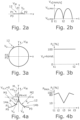
- FIG. 2a An example of a periodic movement that runs along a one-dimensional movement path 12 extending in a transverse direction X perpendicular to the feed direction Y is shown in Fig. 2a This example does not fall under the scope of the present invention.
- the laser beam 3 or the movement path 12 performs an oscillating movement exclusively in the transverse direction X.
- the closed movement path 12 of the laser beam 3 is generated by the beam deflection device 8, whereby in Fig. 2a the movement along the feed direction Y was not taken into account.
- the movement path 12 leads from a Fig. 2a shown first point P1, which represents a first reversal point of the periodic motion in the transverse direction X, via a second point P2, which represents a second reversal point of the periodic motion in the transverse direction X, back to a point P3 whose position coincides with the first point P1.
- Fig. 2b shows the oscillation speed v o of the second scanner mirror 10b, which causes the movement in the transverse direction X perpendicular to the feed direction Y, whereby the three Fig. 2b shown times t 1 , t 2 , t 3 the three in Fig. 2a shown points P1, P2, P3 along the movement path 12.
- Fig. 3a,b shows an example of a periodic movement in which the laser beam 3 runs along a two-dimensional circular movement path 12. This example does not fall within the scope of the present invention.
- the direction of the (vectorial) oscillation speed v o changes depending on the location and continuously, while in Fig. 3b
- the amount v o of the oscillation speed v o remains constant.
- the formation of hot cracks at the fillet weld 7 can be significantly reduced if the superimposed periodic movement of the laser beam 3 takes place along a closed movement path 12 which has at least one stopping point H, as is the case, for example, in Fig. 4a is shown.
- the Fig. 4a The movement path 12 shown runs in the transverse direction X symmetrically to a central axis M containing the stopping point H, which in the example shown corresponds to the Y-axis along which the feed takes place.
- the center axis M shown corresponds to the seam center N of the Fig.1 shown weld 7, ie the weld in Fig. 4a shown deflection of the movement path 12 in (positive and negative) X-direction or in the transverse direction X starts from the seam center N of the weld seam 7.
- Fig. 4a five points P1 to P5 are shown, each of which forms a reversal point of the periodic movement along the two-dimensional movement path 12.
- the movement path 12 runs along a first circular arc 14a in the form of a quarter circle in the direction of the central axis M.
- the first circular arc 14a ends on the central axis M at the second point P2, which corresponds to the stopping point H.
- the second point P2 or the stopping point H forms a front reversal point of the periodic movement along the movement path 12 in the feed direction Y.
- the movement path 12 runs along a second circular arc 14b, which also forms a quarter circle, symmetrically to the central axis M to a third point P3, which forms a right reversal point of the movement path 12 in the transverse direction X.
- the circle center point M2 of the second circular arc 14b also lies on the X-axis and its X-position corresponds to the X-position of the third point P3 along the movement path 12.
- the radius R of the two circular path sections 14a, 14b can be in the order of magnitude of approx. 0.1 mm to approx. 2.5 mm, in particular approx. 0.5 mm.
- the oscillation speed v o or more precisely its speed component v O,Y in the feed direction Y, has a discontinuity:
- the movement path 12 has a speed component v O,Y in the feed direction Y with a positive sign (+v O,Y ).
- the speed component in the feed direction Y has a negative sign (but an identical amount) (-v O,Y ).
- the oscillation speed v o or more precisely its speed component v O,Y in the feed direction Y has a discontinuity:
- the movement path 12 has a speed component v O,Y in the feed direction Y with a positive sign (+v O,Y ).
- the two circular arc-shaped path sections 14a, 14b when reaching the stopping point H, have exclusively a velocity component -v O,Y or +v O,Y in the feed direction Y, but a vanishing velocity component v O,X in the X direction, since the tangent of the two circular arc-shaped path sections 14a, 14b and thus the velocity vector v o at the stopping point H points in the Y direction.
- Fig. 4b shows the time dependence of the laser power P L (in % of the maximum laser power) during the movement of the laser beam 3 along the movement path 12 of Fig. 4a .
- the laser power P L is maximum at the holding point H (at 100%), which is, for example, in the order of magnitude of approx. 5 kW, and minimum at the right-hand reversal point P3, while the laser power P L drops to 80% of the maximum value at the left-hand reversal point P1 or P5.
- the power profile of the laser power P L is thus asymmetrical to the central axis M, although the movement path 12 itself runs symmetrically to the central axis M.
- a profile of the laser power P L that is asymmetrical to the central axis M is advantageous, for example, when welding a fillet weld, since in this case more workpiece material has to be melted on one side of the central axis M than on the other side.
- Fig. 5a shows a location diagram of a two-dimensional movement path 12, which differs from the Fig. 4a shown movement path 12 in that the two end points P1, P3 of the circular arc-shaped path sections 14a, 14b are connected to one another by a semicircular path section 15 which extends from the end points P1, P3 against the feed direction Y, ie in the negative Y direction, to a reversal point P2 of the movement path 12 which is at the rear in the feed direction Y.
- FIG. 1 shows the movement of the laser beam 3 along the weld seam 7, which results from the movement in the feed direction (with feed speed v w ) and the superimposed periodic movement along the Fig. 5a shown movement path 12, as well as the stopping point H.
- Fig. 5b shows analogous to Fig. 4b the time-dependent varying power P L of the laser beam 3 when moving along the movement path 12 of Fig. 5a .
- the laser power P L is at its maximum (at 100%) at the stopping point H (corresponding to P4 or t 4 ) and at its minimum (at approx. 70%) at the rear reversal point P2 in the feed direction Y, while the laser power P L at the left or right reversal points P1 or P3 is at 80% of the maximum value P MAX .
- the power P L is reduced or increased linearly in the manner of a ramp to the minimum value of the power P L at the time t 2 , corresponding to the rear reversal point P2 in the feed direction Y. Accordingly, between the time t 3 and the time t 5 , which correspond to the two reversal points P3, P5 in the transverse direction X, the power P L is increased or decreased in the form of a ramp to the maximum power P MAX .
- Fig. 6a shows a two-dimensional movement path 12, which is different from the one in Fig. 4a and in Fig. 5a shown movement paths 12 are not symmetrical to the central axis M, which corresponds to the seam center N of the weld seam 7.
- the Fig. 6a The two-dimensional movement path 12 shown forms a three-quarter circle, ie it has a circular arc-shaped path section 16 and two straight path sections 17a, 17b extending from a circle center P4, which extend from the circle center P4 in the X direction and in the Y direction to the two end points P1, P3 of the circular arc-shaped path section 16.
- the trajectory 12 shown has a first stopping point H1 and a second stopping point H2 along the central axis M.
- the first stopping point H1 forms, as in the Fig. 4a and in Fig. 5a shown movement paths 12 a front reversal point P5 in the feed direction Y of the periodic movement, wherein at the first stopping point H1 a non-continuous change in direction of the two-dimensional movement path 12 takes place.
- a non-continuous change in direction of the movement path 12 takes place in the form of a change in direction of 90°.
- the speed component v O,X of the periodic movement in the transverse direction X is zero.
- the speed component v O,Y of the movement path 12 in the feed direction Y is correspondingly zero. It has been found that the Fig. 6a
- the movement path 12 shown has proven to be advantageous for certain material combinations of the workpieces 2a, 2b to be joined, for example for fillet welds in hot crack-critical aluminum alloys.
- Fig. 6b shows the time-dependent power P L of laser beam 3, where the times t 1 to t 6 correspond to the points P1 to P6 along the Fig. 6a shown movement path 12.
- the power P L has a maximum value P MAX at the two stopping points H1, H2 and along the linear path section 17a between the two stopping points H1, H2.
- the power P L drops to a minimum value of 20% at the rear reversal point P2 of the movement path 12 in the feed direction Y and has a value of 30% at the two reversal points P1, P3 in the transverse direction X, whereby the power P L increases or decreases linearly between these points (ie P1 and P2 or P2 and P3).
- the power profile P L shown has also proven to be beneficial for influencing the welding process.
- the melted volume can be specifically influenced in the manner described above, particularly when welding fillet welds, but also when welding overlap welds or when welding other weld geometries.
- an improvement in the connection between the workpieces 2a, 2b forming the joining partners can be achieved.
- the material of the workpieces 2a, 2b can be, for example, aluminum or an aluminum alloy, such as those used for bodywork components.
- the procedure described above is not only applicable to the Fig.1 shown fillet weld 7, but also for other welds, for example, for overlap welds, can be used advantageously, for example when welding is to be carried out along a weld in the area in which the two Fig.1 shown workpieces 2a, 2b overlap.
- the method described here can also be used in particular to improve the connection of two workpieces 2a, 2b made of different materials, which otherwise cannot be easily joined using a laser welding process, for example copper and aluminum.
- a processing beam in the form of a laser beam another type of high-energy beam, for example a plasma beam, can also be used to carry out the welding process.
Landscapes
- Physics & Mathematics (AREA)
- Optics & Photonics (AREA)
- Engineering & Computer Science (AREA)
- Plasma & Fusion (AREA)
- Mechanical Engineering (AREA)
- Robotics (AREA)
- Laser Beam Processing (AREA)
Claims (15)
- Procédé d'assemblage d'au moins deux pièces à usiner (2a, 2b), comprenant :la formation d'un joint de soudure (7) en déplaçant un faisceau d'usinage, en particulier un faisceau laser (3), et les au moins deux pièces à usiner (2a, 2b) de manière relative l'un par rapport aux autres le long d'une direction d'avance (Y),où au déplacement du faisceau d'usinage et des deux pièces à usiner (2a, 2b) de manière relative l'un par rapport aux autres est superposé un déplacement périodique dans une trajectoire de déplacement bidimensionnelle (12) qui s'étend dans une direction transversale (X) perpendiculaire à la direction d'avance (Y) et en plus dans la direction d'avance (Y), caractérisé en ce quela trajectoire de déplacement bidimensionnelle (12) présente, entre deux points d'inversion (P3, P5 ; P1, P3), dans la direction transversale (X), au moins un point d'arrêt (H, H1, H2) au niveau duquel une composante de vitesse (vO,X) du déplacement périodique dans la direction transversale (X) est nulle.
- Procédé selon la revendication 1, selon lequel il se produit, au niveau du point d'arrêt (H, H1, H2), un changement de direction non continu de la trajectoire de déplacement bidimensionnelle (12).
- Procédé selon la revendication 1 ou 2, selon lequel le point d'arrêt (H, H1, H2) du déplacement périodique est positionné le long d'un milieu de joint (N) du joint de soudure (7).
- Procédé selon l'une des revendications précédentes, selon lequel le point d'arrêt (H, H1) forme un point d'inversion (P2, P4, P5), en amont dans la direction d'avance (Y), du déplacement périodique le long de la trajectoire de déplacement bidimensionnelle (12).
- Procédé selon l'une des revendications précédentes, selon lequel la trajectoire de déplacement bidimensionnelle (12) présente deux tronçons de trajectoire (14a, 14b) en forme d'arc, en particulier en forme d'arc de cercle, qui se touchent au niveau du point d'arrêt (H, H1), où les deux tronçons de trajectoire (14a, 14b) en forme d'arc présentent, lorsqu'ils atteignent le point d'arrêt (H, H1), exclusivement une composante de vitesse (-vO,Y, +vO,Y) dans la direction d'avance (Y).
- Procédé selon la revendication 5, selon lequel la trajectoire de déplacement (12) présente un autre tronçon de trajectoire (15) en forme d'arc, de préférence en forme de demi-cercle, qui relie entre eux deux points d'extrémité (P3, P5), opposés au point d'arrêt (H), des deux tronçons de trajectoire (14a, 14b) en forme d'arc.
- Procédé selon l'une des revendications précédentes, selon lequel la trajectoire de déplacement bidimensionnelle (12) s'étend dans la direction transversale (X) de manière symétrique ou asymétrique par rapport à un axe central (M) s'étendant dans la direction d'avance (Y) et contenant de préférence le point d'arrêt (H ; H1, H2).
- Procédé selon l'une des revendications précédentes, selon lequel la trajectoire de déplacement bidimensionnelle (12) présente un premier et un deuxième point d'arrêt (H1, H2), où le premier point d'arrêt (H1) forme un point d'inversion (P2, P4 ; P5) dans la direction d'avance (Y) du déplacement périodique le long de la trajectoire de déplacement bidimensionnelle (12), et où le deuxième point d'arrêt (H2) est de préférence relié au premier point d'arrêt (H1) par un tronçon de trajectoire rectiligne (17a).
- Procédé selon la revendication 8, selon lequel la trajectoire de déplacement (12) forme un trois-quarts de cercle avec le deuxième point d'arrêt (H2) comme centre de cercle (P4).
- Procédé selon l'une des revendications précédentes, selon lequel la puissance (PL) du faisceau d'usinage est modifiée lors du déplacement périodique le long de la trajectoire de déplacement (12).
- Procédé selon la revendication 9, selon lequel le faisceau d'usinage présente une puissance maximale (PMAX) au niveau du point d'arrêt (H, H1, H2).
- Procédé selon l'une des revendications précédentes, selon lequel le joint de soudure forme un joint d'angle (7) ou un joint de recouvrement entre les deux pièces à usiner (2a, 2b) à assembler.
- Produit de programme informatique comprenant des instructions de programme pour commander le dispositif selon la revendication 14 conçu pour exécuter toutes les étapes du procédé selon l'une des revendications précédentes lorsque le programme informatique est exécuté sur un système de traitement de données.
- Dispositif (1) destiné à l'assemblage d'au moins deux pièces à usiner (2a, 2b), comprenant :une tête d'usinage (5) destinée à orienter un faisceau d'usinage, en particulier un faisceau laser (3), sur les deux pièces à usiner (2a, 2b), un dispositif de déplacement (6) destiné à déplacer le faisceau d'usinage (3) et les au moins deux pièces à usiner (2a, 2b) de manière relative l'un par rapport aux autres le long d'une direction d'avance (Y) en formant un joint de soudure (7),un dispositif de déflexion de faisceau (8) destiné à dévier le faisceau d'usinage, ainsi qu'un dispositif de commande (13) destiné à commander le dispositif de déflexion de faisceau (8) et/ou le dispositif de déplacement (6) pour produire un déplacement périodique du faisceau d'usinage, superposé au déplacement relatif entre le faisceau d'usinage et les deux pièces à usiner (2a, 2b) le long de la direction d'avance (Y), le long d'une trajectoire de déplacement bidimensionnelle (12) qui s'étend dans une direction transversale (X) perpendiculaire à la direction d'avance (Y) ainsi que dans la direction d'avance (Y),caractérisé en ce quele dispositif de commande (13) destiné à commander le dispositif de déflexion de faisceau (8) est conçu pour générer une trajectoire de déplacement bidimensionnelle (12) qui présente, entre deux points d'inversion (P3, P5 ; P1, P3) dans la direction transversale (X), au moins un point d'arrêt (H, H1, H2) au niveau duquel une composante de vitesse (vO,X) du déplacement périodique dans la direction transversale (X) est nulle, où il se produit, au niveau de l'au moins un point d'arrêt (H, H1, H2), de préférence un changement de direction non continu de la trajectoire de déplacement bidimensionnelle (12).
- Dispositif selon la revendication 14, selon lequel le dispositif de déflexion de faisceau (8) présente au moins deux miroirs de balayage (10a, 10b) destinés à dévier le faisceau d'usinage (3).
Applications Claiming Priority (2)
| Application Number | Priority Date | Filing Date | Title |
|---|---|---|---|
| DE102017211982.9A DE102017211982B4 (de) | 2017-07-13 | 2017-07-13 | Verfahren und Vorrichtung zum Fügen von mindestens zwei Werkstücken |
| PCT/EP2018/068499 WO2019011838A1 (fr) | 2017-07-13 | 2018-07-09 | Procédé et dispositif pour l'assemblage bout à bout d'au moins deux pièces |
Publications (2)
| Publication Number | Publication Date |
|---|---|
| EP3651932A1 EP3651932A1 (fr) | 2020-05-20 |
| EP3651932B1 true EP3651932B1 (fr) | 2024-06-26 |
Family
ID=62976025
Family Applications (1)
| Application Number | Title | Priority Date | Filing Date |
|---|---|---|---|
| EP18742959.2A Active EP3651932B1 (fr) | 2017-07-13 | 2018-07-09 | Procédé et dispositif pour l'assemblage bout à bout d'au moins deux pièces |
Country Status (7)
| Country | Link |
|---|---|
| US (1) | US11565348B2 (fr) |
| EP (1) | EP3651932B1 (fr) |
| JP (1) | JP7014823B2 (fr) |
| KR (1) | KR102355226B1 (fr) |
| CN (1) | CN110869158B (fr) |
| DE (1) | DE102017211982B4 (fr) |
| WO (1) | WO2019011838A1 (fr) |
Families Citing this family (8)
| Publication number | Priority date | Publication date | Assignee | Title |
|---|---|---|---|---|
| DE102017211982B4 (de) | 2017-07-13 | 2019-04-18 | Trumpf Laser- Und Systemtechnik Gmbh | Verfahren und Vorrichtung zum Fügen von mindestens zwei Werkstücken |
| US20230066980A1 (en) * | 2019-12-19 | 2023-03-02 | Lg Energy Solution, Ltd. | Battery module and method of manufacturing the same |
| JP7752291B2 (ja) * | 2020-05-14 | 2025-10-10 | パナソニックIpマネジメント株式会社 | レーザ溶接方法及びレーザ溶接装置 |
| CN111633336B (zh) * | 2020-05-22 | 2022-03-22 | 哈尔滨焊接研究院有限公司 | 一种提高焊接过程稳定性的激光矢量焊接方法 |
| JP7515074B2 (ja) * | 2020-06-19 | 2024-07-12 | パナソニックIpマネジメント株式会社 | レーザ溶接方法および装置 |
| CN113182686B (zh) * | 2021-03-23 | 2025-10-03 | 昆山华恒焊接股份有限公司 | 激光焊接系统、激光焊接控制方法、装置及存储介质 |
| RU2768618C1 (ru) * | 2021-06-29 | 2022-03-24 | Акционерное общество "Государственный научный центр Российской Федерации Троицкий институт инновационных и термоядерных исследований" АО "ГНЦ РФ ТРИНИТИ" | Способ лазерной сварки |
| DE102024130668A1 (de) | 2024-10-22 | 2026-04-23 | TRUMPF Laser- und Systemtechnik SE | Verfahren zum Bestimmen der Einschweißtiefe bei einem Laserschweißprozess |
Citations (1)
| Publication number | Priority date | Publication date | Assignee | Title |
|---|---|---|---|---|
| CN103056533A (zh) * | 2012-12-20 | 2013-04-24 | 华中科技大学 | 一种振荡扫描激光束-电弧复合焊接方法及系统 |
Family Cites Families (39)
| Publication number | Priority date | Publication date | Assignee | Title |
|---|---|---|---|---|
| SE401637B (sv) * | 1976-03-29 | 1978-05-22 | Asea Ab | Forfarande och anordning for att bringa en industrirobot att utfora en komplex rorelse |
| US4621333A (en) * | 1983-08-31 | 1986-11-04 | Mitsubishi Denki Kabushiki Kaisha | Method and apparatus for controlling a robot to perform weaving-like motion |
| JPH06320462A (ja) * | 1993-05-10 | 1994-11-22 | Fanuc Ltd | センサ付きロボットの制御方法 |
| JP3238077B2 (ja) * | 1996-08-28 | 2001-12-10 | 新日本製鐵株式会社 | めっき鋼板の重ねレーザ溶接方法 |
| US6740845B2 (en) | 2002-05-24 | 2004-05-25 | Alcoa Inc. | Laser welding with beam oscillation |
| US7479616B2 (en) * | 2004-04-20 | 2009-01-20 | General Motors Corporation | Compound laser beam welding |
| US7910855B2 (en) * | 2005-09-23 | 2011-03-22 | Lasx Industries, Inc. | No gap laser welding of coated steel |
| JP2010264494A (ja) * | 2009-05-15 | 2010-11-25 | Miyachi Technos Corp | レーザ加工装置及びレーザ加工方法 |
| CN102091889A (zh) * | 2010-11-27 | 2011-06-15 | 东方电气集团东方汽轮机有限公司 | 一种堆焊方法及其装置 |
| JP5459256B2 (ja) * | 2011-04-08 | 2014-04-02 | 株式会社安川電機 | ロボットシステム |
| DE102012008940B4 (de) | 2012-05-08 | 2022-03-24 | Fraunhofer-Gesellschaft zur Förderung der angewandten Forschung e.V. | Verfahren zum Fügen von mindestens zwei Werkstücken |
| US8941031B2 (en) * | 2012-08-22 | 2015-01-27 | Caterpillar Inc. | Systems and methods for dual-weave welding |
| DE102013110523B4 (de) | 2013-09-24 | 2016-08-18 | Scansonic Mi Gmbh | Vorrichtung und Verfahren zum Fügen von Werkstücken mittels Laserstrahls |
| DE102013219220B4 (de) | 2013-09-25 | 2025-02-06 | Bayerische Motoren Werke Aktiengesellschaft | Verfahren zum Laser- Remote Bearbeiten eines Werkstücks an einer Kehle und Vorrichtung hierfür |
| EP2893994B1 (fr) * | 2014-01-14 | 2020-07-15 | General Electric Technology GmbH | Procédé de fabrication d'un composant métallique ou céramique par fusion laser sélective |
| CN105555465B (zh) * | 2014-02-25 | 2017-05-10 | 松下知识产权经营株式会社 | 激光焊接方法 |
| DE102014206302A1 (de) | 2014-04-02 | 2015-10-08 | Fraunhofer-Gesellschaft zur Förderung der angewandten Forschung e.V. | Verfahren zum Schweißen |
| DE102014210118A1 (de) | 2014-05-27 | 2015-12-03 | Siemens Aktiengesellschaft | Optik mit beweglichem Innengehäuse zum Schweißen mit oszillierenden Strahlen und Schweißverfahren |
| DE102014210486B4 (de) * | 2014-06-03 | 2016-08-04 | Lpkf Laser & Electronics Ag | Verfahren zum Verschweißen zweier Fügepartner aus thermoplastischen Kunststoffen entlang einer Schweißnaht mittels Laser |
| DE102014015094A1 (de) | 2014-10-10 | 2016-04-14 | Audi Ag | Verfahren zum Laserstrahlschweißen |
| JP6967700B2 (ja) * | 2015-06-01 | 2021-11-17 | パナソニックIpマネジメント株式会社 | レーザ溶接方法、レーザ溶接条件決定方法、およびレーザ溶接システム |
| CN104999179A (zh) * | 2015-08-04 | 2015-10-28 | 大族激光科技产业集团股份有限公司 | 一种大间隙焊缝的激光焊接方法 |
| DE112015006848T5 (de) * | 2015-08-31 | 2018-05-17 | GM Global Technology Operations LLC | Verfahren zum Laserschweissen von Werkstücken aus Aluminium |
| KR101796198B1 (ko) * | 2015-08-31 | 2017-11-09 | 주식회사 이오테크닉스 | 레이저 가공장치 및 이를 이용한 레이저 가공방법 |
| CN108140494A (zh) * | 2015-10-01 | 2018-06-08 | 太阳诱电株式会社 | 蓄电组件、蓄电组件的制造方法、金属接合体和金属接合体的制造方法 |
| DE102015223446A1 (de) * | 2015-11-26 | 2017-06-01 | Bayerische Motoren Werke Aktiengesellschaft | Verfahren zum Remote-Laserstrahlschweißen |
| DE102016107581B3 (de) * | 2016-02-16 | 2017-04-13 | Scansonic Mi Gmbh | Schweißverfahren zum Verbinden von Werkstücken an einem Überlappstoß |
| JP6771288B2 (ja) * | 2016-02-17 | 2020-10-21 | 株式会社神戸製鋼所 | 溶接装置及び溶接装置の制御方法 |
| US10799986B2 (en) * | 2016-06-27 | 2020-10-13 | Illinois Tool Works Inc. | Wide path welding, cladding, additive manufacturing |
| US20180021888A1 (en) * | 2016-07-22 | 2018-01-25 | Illinois Tool Works Inc. | Laser welding systems for aluminum alloys and methods of laser welding aluminum alloys |
| DE102017211982B4 (de) | 2017-07-13 | 2019-04-18 | Trumpf Laser- Und Systemtechnik Gmbh | Verfahren und Vorrichtung zum Fügen von mindestens zwei Werkstücken |
| EP3441178A1 (fr) * | 2017-08-09 | 2019-02-13 | Autotech Engineering A.I.E. | Procédé d'assemblage de deux ébauches |
| JP6948888B2 (ja) * | 2017-08-31 | 2021-10-13 | 株式会社神戸製鋼所 | 接合体の製造方法及び接合体の製造装置 |
| DE102017126867A1 (de) * | 2017-11-15 | 2019-05-16 | Precitec Gmbh & Co. Kg | Laserbearbeitungssystem und Verfahren zur Laserbearbeitung |
| EP3517241A1 (fr) * | 2018-01-29 | 2019-07-31 | Bystronic Laser AG | Dispositif optique permettant de mettre en forme un faisceau d'ondes électromagnétiques et son utilisation, dispositif de traitement de faisceau et son utilisation et procédé de traitement de faisceau |
| JP6740267B2 (ja) * | 2018-02-19 | 2020-08-12 | ファナック株式会社 | レーザ加工装置 |
| MX2021000687A (es) * | 2018-07-19 | 2021-03-25 | Ipg Photonics Corp | Sistemas y metodos de monitoreo y/o control de procesamiento por oscilacion que utiliza formacion de imagen coherente en linea (ici). |
| US11305366B2 (en) * | 2019-01-04 | 2022-04-19 | Lincoln Global, Inc. | Systems and methods providing dynamic bead spacing and weave fill in additive manufacturing |
| JP7515074B2 (ja) * | 2020-06-19 | 2024-07-12 | パナソニックIpマネジメント株式会社 | レーザ溶接方法および装置 |
-
2017
- 2017-07-13 DE DE102017211982.9A patent/DE102017211982B4/de not_active Expired - Fee Related
-
2018
- 2018-07-09 WO PCT/EP2018/068499 patent/WO2019011838A1/fr not_active Ceased
- 2018-07-09 EP EP18742959.2A patent/EP3651932B1/fr active Active
- 2018-07-09 CN CN201880046634.7A patent/CN110869158B/zh active Active
- 2018-07-09 JP JP2019569237A patent/JP7014823B2/ja active Active
- 2018-07-09 KR KR1020207000749A patent/KR102355226B1/ko active Active
-
2020
- 2020-01-10 US US16/739,658 patent/US11565348B2/en active Active
Patent Citations (1)
| Publication number | Priority date | Publication date | Assignee | Title |
|---|---|---|---|---|
| CN103056533A (zh) * | 2012-12-20 | 2013-04-24 | 华中科技大学 | 一种振荡扫描激光束-电弧复合焊接方法及系统 |
Also Published As
| Publication number | Publication date |
|---|---|
| WO2019011838A1 (fr) | 2019-01-17 |
| KR102355226B1 (ko) | 2022-02-08 |
| DE102017211982A1 (de) | 2019-01-17 |
| US11565348B2 (en) | 2023-01-31 |
| KR20200030531A (ko) | 2020-03-20 |
| JP7014823B2 (ja) | 2022-02-01 |
| DE102017211982B4 (de) | 2019-04-18 |
| EP3651932A1 (fr) | 2020-05-20 |
| JP2020526395A (ja) | 2020-08-31 |
| US20200147723A1 (en) | 2020-05-14 |
| CN110869158A (zh) | 2020-03-06 |
| CN110869158B (zh) | 2022-04-01 |
Similar Documents
| Publication | Publication Date | Title |
|---|---|---|
| EP3651932B1 (fr) | Procédé et dispositif pour l'assemblage bout à bout d'au moins deux pièces | |
| EP2160266B1 (fr) | Procédé d'assemblage par soudure de pièces métalliques à parois épaisses | |
| DE102015104411B4 (de) | Laserstrahlfügeverfahren und Laserbearbeitungsoptik | |
| EP2205393B1 (fr) | Dispositif et procédé d'usinage au laser | |
| DE102012008940B4 (de) | Verfahren zum Fügen von mindestens zwei Werkstücken | |
| DE102007038502B4 (de) | Verfahren zum Fügen von mindestens zwei Werkstücken mittels eines Laserstrahls | |
| EP3157706B1 (fr) | Procédé de soudage par faisceau laser de deux éléments de jonction associés ou plus au moyen d'un guidage optique de joint de soudure et d'un dispositif de balayage avec oscillation superposée de miroirs oscillants | |
| EP3484656A1 (fr) | Procédé et machine d'usinage laser destinés au soudage laser d'une première et d'une deuxième sections d'une pièce à usiner | |
| DE102013107228B3 (de) | Verfahren zum stirnseitigen Laserstrahlschweißen von Bördelflanschen | |
| DE102014203025A1 (de) | Verfahren zum Laserstrahlschweißen und Schweißkopf | |
| EP2117762A2 (fr) | Procédé et dispositif de soudage laser | |
| WO2020109209A1 (fr) | Dispositif et procédé de formation et de modulation de faisceau dans le traitement de matériaux au laser | |
| EP1175955B1 (fr) | Procédé et dispositif de lissage de cordon soudé au cours du soudage par faisceau | |
| DE19608074C2 (de) | Verfahren zum Schweißen von relativbewegten Werkstücken | |
| DE102004050819B4 (de) | Verfahren und Vorrichtung zum Laserstrahlbearbeiten | |
| DE102018127649B4 (de) | Verfahren zum Laserschweißen mit stabilem Schmelzbad und Laserbearbeitungsvorrichtung | |
| WO2018041463A1 (fr) | Procédé et dispositif pour souder entre eux des partenaires d'assemblage | |
| EP0889769B1 (fr) | Procede pour assembler des pieces au moyen d'un faisceau laser | |
| DE10304709B4 (de) | Verfahren und Vorrichtung zum Laser-Hybridschweißen | |
| DE102024001169B4 (de) | Verfahren zum Verschweißen von Bauteilen mit unterschiedlicher Materialstärke | |
| DE102004026427B4 (de) | Verwendung einer Vorrichtung zur Behandlung eines Substrates mittels Laserstrahlen und Vorrichtung zur Behandlung des Substrates | |
| DE20101452U1 (de) | Bearbeitungsvorrichtung | |
| EP3424636A1 (fr) | Système de soudage laser comprenant un dispositif pousseur, une optique d'usinage et au moins un dispositif de guidage tactile | |
| EP4479217A2 (fr) | Procédé pour revêtir des pièces métalliques | |
| WO2019030016A1 (fr) | Dispositif pour soudage laser manuel |
Legal Events
| Date | Code | Title | Description |
|---|---|---|---|
| STAA | Information on the status of an ep patent application or granted ep patent |
Free format text: STATUS: UNKNOWN |
|
| STAA | Information on the status of an ep patent application or granted ep patent |
Free format text: STATUS: THE INTERNATIONAL PUBLICATION HAS BEEN MADE |
|
| PUAI | Public reference made under article 153(3) epc to a published international application that has entered the european phase |
Free format text: ORIGINAL CODE: 0009012 |
|
| STAA | Information on the status of an ep patent application or granted ep patent |
Free format text: STATUS: REQUEST FOR EXAMINATION WAS MADE |
|
| 17P | Request for examination filed |
Effective date: 20200213 |
|
| AK | Designated contracting states |
Kind code of ref document: A1 Designated state(s): AL AT BE BG CH CY CZ DE DK EE ES FI FR GB GR HR HU IE IS IT LI LT LU LV MC MK MT NL NO PL PT RO RS SE SI SK SM TR |
|
| AX | Request for extension of the european patent |
Extension state: BA ME |
|
| DAV | Request for validation of the european patent (deleted) | ||
| DAX | Request for extension of the european patent (deleted) | ||
| STAA | Information on the status of an ep patent application or granted ep patent |
Free format text: STATUS: EXAMINATION IS IN PROGRESS |
|
| 17Q | First examination report despatched |
Effective date: 20230223 |
|
| GRAP | Despatch of communication of intention to grant a patent |
Free format text: ORIGINAL CODE: EPIDOSNIGR1 |
|
| STAA | Information on the status of an ep patent application or granted ep patent |
Free format text: STATUS: GRANT OF PATENT IS INTENDED |
|
| INTG | Intention to grant announced |
Effective date: 20240123 |
|
| GRAS | Grant fee paid |
Free format text: ORIGINAL CODE: EPIDOSNIGR3 |
|
| GRAA | (expected) grant |
Free format text: ORIGINAL CODE: 0009210 |
|
| STAA | Information on the status of an ep patent application or granted ep patent |
Free format text: STATUS: THE PATENT HAS BEEN GRANTED |
|
| AK | Designated contracting states |
Kind code of ref document: B1 Designated state(s): AL AT BE BG CH CY CZ DE DK EE ES FI FR GB GR HR HU IE IS IT LI LT LU LV MC MK MT NL NO PL PT RO RS SE SI SK SM TR |
|
| REG | Reference to a national code |
Ref country code: GB Ref legal event code: FG4D Free format text: NOT ENGLISH |
|
| REG | Reference to a national code |
Ref country code: CH Ref legal event code: EP |
|
| REG | Reference to a national code |
Ref country code: DE Ref legal event code: R081 Ref document number: 502018014778 Country of ref document: DE Owner name: TRUMPF LASER- UND SYSTEMTECHNIK SE, DE Free format text: FORMER OWNER: ANMELDERANGABEN UNKLAR / UNVOLLSTAENDIG, 80297 MUENCHEN, DE |
|
| REG | Reference to a national code |
Ref country code: DE Ref legal event code: R081 Ref document number: 502018014778 Country of ref document: DE Owner name: TRUMPF LASER- UND SYSTEMTECHNIK SE, DE Free format text: FORMER OWNER: TRUMPF LASER UND SYSTEMTECHNIK GMBH, 71254 DITZINGEN, DE |
|
| REG | Reference to a national code |
Ref country code: DE Ref legal event code: R096 Ref document number: 502018014778 Country of ref document: DE |
|
| REG | Reference to a national code |
Ref country code: DE Ref legal event code: R082 Ref document number: 502018014778 Country of ref document: DE |
|
| RAP2 | Party data changed (patent owner data changed or rights of a patent transferred) |
Owner name: TRUMPF LASER- UND SYSTEMTECHNIK SE |
|
| PG25 | Lapsed in a contracting state [announced via postgrant information from national office to epo] |
Ref country code: BG Free format text: LAPSE BECAUSE OF FAILURE TO SUBMIT A TRANSLATION OF THE DESCRIPTION OR TO PAY THE FEE WITHIN THE PRESCRIBED TIME-LIMIT Effective date: 20240626 |
|
| PG25 | Lapsed in a contracting state [announced via postgrant information from national office to epo] |
Ref country code: FI Free format text: LAPSE BECAUSE OF FAILURE TO SUBMIT A TRANSLATION OF THE DESCRIPTION OR TO PAY THE FEE WITHIN THE PRESCRIBED TIME-LIMIT Effective date: 20240626 Ref country code: HR Free format text: LAPSE BECAUSE OF FAILURE TO SUBMIT A TRANSLATION OF THE DESCRIPTION OR TO PAY THE FEE WITHIN THE PRESCRIBED TIME-LIMIT Effective date: 20240626 |
|
| REG | Reference to a national code |
Ref country code: LT Ref legal event code: MG9D |
|
| PG25 | Lapsed in a contracting state [announced via postgrant information from national office to epo] |
Ref country code: GR Free format text: LAPSE BECAUSE OF FAILURE TO SUBMIT A TRANSLATION OF THE DESCRIPTION OR TO PAY THE FEE WITHIN THE PRESCRIBED TIME-LIMIT Effective date: 20240927 |
|
| PG25 | Lapsed in a contracting state [announced via postgrant information from national office to epo] |
Ref country code: LV Free format text: LAPSE BECAUSE OF FAILURE TO SUBMIT A TRANSLATION OF THE DESCRIPTION OR TO PAY THE FEE WITHIN THE PRESCRIBED TIME-LIMIT Effective date: 20240626 |
|
| REG | Reference to a national code |
Ref country code: NL Ref legal event code: MP Effective date: 20240626 |
|
| PG25 | Lapsed in a contracting state [announced via postgrant information from national office to epo] |
Ref country code: NO Free format text: LAPSE BECAUSE OF FAILURE TO SUBMIT A TRANSLATION OF THE DESCRIPTION OR TO PAY THE FEE WITHIN THE PRESCRIBED TIME-LIMIT Effective date: 20240926 Ref country code: LV Free format text: LAPSE BECAUSE OF FAILURE TO SUBMIT A TRANSLATION OF THE DESCRIPTION OR TO PAY THE FEE WITHIN THE PRESCRIBED TIME-LIMIT Effective date: 20240626 Ref country code: HR Free format text: LAPSE BECAUSE OF FAILURE TO SUBMIT A TRANSLATION OF THE DESCRIPTION OR TO PAY THE FEE WITHIN THE PRESCRIBED TIME-LIMIT Effective date: 20240626 Ref country code: GR Free format text: LAPSE BECAUSE OF FAILURE TO SUBMIT A TRANSLATION OF THE DESCRIPTION OR TO PAY THE FEE WITHIN THE PRESCRIBED TIME-LIMIT Effective date: 20240927 Ref country code: FI Free format text: LAPSE BECAUSE OF FAILURE TO SUBMIT A TRANSLATION OF THE DESCRIPTION OR TO PAY THE FEE WITHIN THE PRESCRIBED TIME-LIMIT Effective date: 20240626 Ref country code: BG Free format text: LAPSE BECAUSE OF FAILURE TO SUBMIT A TRANSLATION OF THE DESCRIPTION OR TO PAY THE FEE WITHIN THE PRESCRIBED TIME-LIMIT Effective date: 20240626 Ref country code: RS Free format text: LAPSE BECAUSE OF FAILURE TO SUBMIT A TRANSLATION OF THE DESCRIPTION OR TO PAY THE FEE WITHIN THE PRESCRIBED TIME-LIMIT Effective date: 20240926 |
|
| PG25 | Lapsed in a contracting state [announced via postgrant information from national office to epo] |
Ref country code: NL Free format text: LAPSE BECAUSE OF FAILURE TO SUBMIT A TRANSLATION OF THE DESCRIPTION OR TO PAY THE FEE WITHIN THE PRESCRIBED TIME-LIMIT Effective date: 20240626 |
|
| PG25 | Lapsed in a contracting state [announced via postgrant information from national office to epo] |
Ref country code: NL Free format text: LAPSE BECAUSE OF FAILURE TO SUBMIT A TRANSLATION OF THE DESCRIPTION OR TO PAY THE FEE WITHIN THE PRESCRIBED TIME-LIMIT Effective date: 20240626 |
|
| PG25 | Lapsed in a contracting state [announced via postgrant information from national office to epo] |
Ref country code: PT Free format text: LAPSE BECAUSE OF FAILURE TO SUBMIT A TRANSLATION OF THE DESCRIPTION OR TO PAY THE FEE WITHIN THE PRESCRIBED TIME-LIMIT Effective date: 20241028 |
|
| PG25 | Lapsed in a contracting state [announced via postgrant information from national office to epo] |
Ref country code: PT Free format text: LAPSE BECAUSE OF FAILURE TO SUBMIT A TRANSLATION OF THE DESCRIPTION OR TO PAY THE FEE WITHIN THE PRESCRIBED TIME-LIMIT Effective date: 20241028 |
|
| PG25 | Lapsed in a contracting state [announced via postgrant information from national office to epo] |
Ref country code: PL Free format text: LAPSE BECAUSE OF FAILURE TO SUBMIT A TRANSLATION OF THE DESCRIPTION OR TO PAY THE FEE WITHIN THE PRESCRIBED TIME-LIMIT Effective date: 20240626 |
|
| PG25 | Lapsed in a contracting state [announced via postgrant information from national office to epo] |
Ref country code: EE Free format text: LAPSE BECAUSE OF FAILURE TO SUBMIT A TRANSLATION OF THE DESCRIPTION OR TO PAY THE FEE WITHIN THE PRESCRIBED TIME-LIMIT Effective date: 20240626 |
|
| PG25 | Lapsed in a contracting state [announced via postgrant information from national office to epo] |
Ref country code: IS Free format text: LAPSE BECAUSE OF FAILURE TO SUBMIT A TRANSLATION OF THE DESCRIPTION OR TO PAY THE FEE WITHIN THE PRESCRIBED TIME-LIMIT Effective date: 20241026 |
|
| PG25 | Lapsed in a contracting state [announced via postgrant information from national office to epo] |
Ref country code: CZ Free format text: LAPSE BECAUSE OF FAILURE TO SUBMIT A TRANSLATION OF THE DESCRIPTION OR TO PAY THE FEE WITHIN THE PRESCRIBED TIME-LIMIT Effective date: 20240626 |
|
| PG25 | Lapsed in a contracting state [announced via postgrant information from national office to epo] |
Ref country code: RO Free format text: LAPSE BECAUSE OF FAILURE TO SUBMIT A TRANSLATION OF THE DESCRIPTION OR TO PAY THE FEE WITHIN THE PRESCRIBED TIME-LIMIT Effective date: 20240626 Ref country code: SK Free format text: LAPSE BECAUSE OF FAILURE TO SUBMIT A TRANSLATION OF THE DESCRIPTION OR TO PAY THE FEE WITHIN THE PRESCRIBED TIME-LIMIT Effective date: 20240626 |
|
| PG25 | Lapsed in a contracting state [announced via postgrant information from national office to epo] |
Ref country code: ES Free format text: LAPSE BECAUSE OF FAILURE TO SUBMIT A TRANSLATION OF THE DESCRIPTION OR TO PAY THE FEE WITHIN THE PRESCRIBED TIME-LIMIT Effective date: 20240626 Ref country code: SM Free format text: LAPSE BECAUSE OF FAILURE TO SUBMIT A TRANSLATION OF THE DESCRIPTION OR TO PAY THE FEE WITHIN THE PRESCRIBED TIME-LIMIT Effective date: 20240626 |
|
| PG25 | Lapsed in a contracting state [announced via postgrant information from national office to epo] |
Ref country code: SM Free format text: LAPSE BECAUSE OF FAILURE TO SUBMIT A TRANSLATION OF THE DESCRIPTION OR TO PAY THE FEE WITHIN THE PRESCRIBED TIME-LIMIT Effective date: 20240626 Ref country code: SK Free format text: LAPSE BECAUSE OF FAILURE TO SUBMIT A TRANSLATION OF THE DESCRIPTION OR TO PAY THE FEE WITHIN THE PRESCRIBED TIME-LIMIT Effective date: 20240626 Ref country code: RO Free format text: LAPSE BECAUSE OF FAILURE TO SUBMIT A TRANSLATION OF THE DESCRIPTION OR TO PAY THE FEE WITHIN THE PRESCRIBED TIME-LIMIT Effective date: 20240626 Ref country code: PL Free format text: LAPSE BECAUSE OF FAILURE TO SUBMIT A TRANSLATION OF THE DESCRIPTION OR TO PAY THE FEE WITHIN THE PRESCRIBED TIME-LIMIT Effective date: 20240626 Ref country code: IS Free format text: LAPSE BECAUSE OF FAILURE TO SUBMIT A TRANSLATION OF THE DESCRIPTION OR TO PAY THE FEE WITHIN THE PRESCRIBED TIME-LIMIT Effective date: 20241026 Ref country code: ES Free format text: LAPSE BECAUSE OF FAILURE TO SUBMIT A TRANSLATION OF THE DESCRIPTION OR TO PAY THE FEE WITHIN THE PRESCRIBED TIME-LIMIT Effective date: 20240626 Ref country code: EE Free format text: LAPSE BECAUSE OF FAILURE TO SUBMIT A TRANSLATION OF THE DESCRIPTION OR TO PAY THE FEE WITHIN THE PRESCRIBED TIME-LIMIT Effective date: 20240626 Ref country code: CZ Free format text: LAPSE BECAUSE OF FAILURE TO SUBMIT A TRANSLATION OF THE DESCRIPTION OR TO PAY THE FEE WITHIN THE PRESCRIBED TIME-LIMIT Effective date: 20240626 |
|
| PG25 | Lapsed in a contracting state [announced via postgrant information from national office to epo] |
Ref country code: IT Free format text: LAPSE BECAUSE OF FAILURE TO SUBMIT A TRANSLATION OF THE DESCRIPTION OR TO PAY THE FEE WITHIN THE PRESCRIBED TIME-LIMIT Effective date: 20240626 |
|
| REG | Reference to a national code |
Ref country code: CH Ref legal event code: PL |
|
| PG25 | Lapsed in a contracting state [announced via postgrant information from national office to epo] |
Ref country code: LU Free format text: LAPSE BECAUSE OF NON-PAYMENT OF DUE FEES Effective date: 20240709 |
|
| PG25 | Lapsed in a contracting state [announced via postgrant information from national office to epo] |
Ref country code: MC Free format text: LAPSE BECAUSE OF FAILURE TO SUBMIT A TRANSLATION OF THE DESCRIPTION OR TO PAY THE FEE WITHIN THE PRESCRIBED TIME-LIMIT Effective date: 20240626 |
|
| REG | Reference to a national code |
Ref country code: DE Ref legal event code: R097 Ref document number: 502018014778 Country of ref document: DE |
|
| PG25 | Lapsed in a contracting state [announced via postgrant information from national office to epo] |
Ref country code: MC Free format text: LAPSE BECAUSE OF FAILURE TO SUBMIT A TRANSLATION OF THE DESCRIPTION OR TO PAY THE FEE WITHIN THE PRESCRIBED TIME-LIMIT Effective date: 20240626 Ref country code: LU Free format text: LAPSE BECAUSE OF NON-PAYMENT OF DUE FEES Effective date: 20240709 |
|
| PG25 | Lapsed in a contracting state [announced via postgrant information from national office to epo] |
Ref country code: DK Free format text: LAPSE BECAUSE OF FAILURE TO SUBMIT A TRANSLATION OF THE DESCRIPTION OR TO PAY THE FEE WITHIN THE PRESCRIBED TIME-LIMIT Effective date: 20240626 |
|
| PG25 | Lapsed in a contracting state [announced via postgrant information from national office to epo] |
Ref country code: CH Free format text: LAPSE BECAUSE OF NON-PAYMENT OF DUE FEES Effective date: 20240731 Ref country code: BE Free format text: LAPSE BECAUSE OF NON-PAYMENT OF DUE FEES Effective date: 20240731 |
|
| PLBE | No opposition filed within time limit |
Free format text: ORIGINAL CODE: 0009261 |
|
| STAA | Information on the status of an ep patent application or granted ep patent |
Free format text: STATUS: NO OPPOSITION FILED WITHIN TIME LIMIT |
|
| GBPC | Gb: european patent ceased through non-payment of renewal fee |
Effective date: 20240926 |
|
| 26N | No opposition filed |
Effective date: 20250327 |
|
| REG | Reference to a national code |
Ref country code: BE Ref legal event code: MM Effective date: 20240731 |
|
| PG25 | Lapsed in a contracting state [announced via postgrant information from national office to epo] |
Ref country code: GB Free format text: LAPSE BECAUSE OF NON-PAYMENT OF DUE FEES Effective date: 20240926 |
|
| PG25 | Lapsed in a contracting state [announced via postgrant information from national office to epo] |
Ref country code: FR Free format text: LAPSE BECAUSE OF NON-PAYMENT OF DUE FEES Effective date: 20240826 |
|
| PG25 | Lapsed in a contracting state [announced via postgrant information from national office to epo] |
Ref country code: IE Free format text: LAPSE BECAUSE OF NON-PAYMENT OF DUE FEES Effective date: 20240709 |
|
| PG25 | Lapsed in a contracting state [announced via postgrant information from national office to epo] |
Ref country code: SE Free format text: LAPSE BECAUSE OF FAILURE TO SUBMIT A TRANSLATION OF THE DESCRIPTION OR TO PAY THE FEE WITHIN THE PRESCRIBED TIME-LIMIT Effective date: 20240626 |
|
| REG | Reference to a national code |
Ref country code: AT Ref legal event code: MM01 Ref document number: 1697310 Country of ref document: AT Kind code of ref document: T Effective date: 20240709 |
|
| PGFP | Annual fee paid to national office [announced via postgrant information from national office to epo] |
Ref country code: DE Payment date: 20250722 Year of fee payment: 8 |
|
| PG25 | Lapsed in a contracting state [announced via postgrant information from national office to epo] |
Ref country code: AT Free format text: LAPSE BECAUSE OF NON-PAYMENT OF DUE FEES Effective date: 20240709 |
|
| PG25 | Lapsed in a contracting state [announced via postgrant information from national office to epo] |
Ref country code: CY Free format text: LAPSE BECAUSE OF FAILURE TO SUBMIT A TRANSLATION OF THE DESCRIPTION OR TO PAY THE FEE WITHIN THE PRESCRIBED TIME-LIMIT; INVALID AB INITIO Effective date: 20180709 |
|
| PG25 | Lapsed in a contracting state [announced via postgrant information from national office to epo] |
Ref country code: HU Free format text: LAPSE BECAUSE OF FAILURE TO SUBMIT A TRANSLATION OF THE DESCRIPTION OR TO PAY THE FEE WITHIN THE PRESCRIBED TIME-LIMIT; INVALID AB INITIO Effective date: 20180709 |