EP3652460B1 - Kupplungssystem, insbesondere für doppelfedermodule - Google Patents
Kupplungssystem, insbesondere für doppelfedermodule Download PDFInfo
- Publication number
- EP3652460B1 EP3652460B1 EP18737271.9A EP18737271A EP3652460B1 EP 3652460 B1 EP3652460 B1 EP 3652460B1 EP 18737271 A EP18737271 A EP 18737271A EP 3652460 B1 EP3652460 B1 EP 3652460B1
- Authority
- EP
- European Patent Office
- Prior art keywords
- spring
- twin
- coupling system
- disk
- coupled
- Prior art date
- Legal status (The legal status is an assumption and is not a legal conclusion. Google has not performed a legal analysis and makes no representation as to the accuracy of the status listed.)
- Active
Links
Images


Classifications
-
- F—MECHANICAL ENGINEERING; LIGHTING; HEATING; WEAPONS; BLASTING
- F16—ENGINEERING ELEMENTS AND UNITS; GENERAL MEASURES FOR PRODUCING AND MAINTAINING EFFECTIVE FUNCTIONING OF MACHINES OR INSTALLATIONS; THERMAL INSULATION IN GENERAL
- F16F—SPRINGS; SHOCK-ABSORBERS; MEANS FOR DAMPING VIBRATION
- F16F3/00—Spring units consisting of several springs, e.g. for obtaining a desired spring characteristic
- F16F3/02—Spring units consisting of several springs, e.g. for obtaining a desired spring characteristic with springs made of steel or of other material having low internal friction
- F16F3/04—Spring units consisting of several springs, e.g. for obtaining a desired spring characteristic with springs made of steel or of other material having low internal friction composed only of wound springs
-
- F—MECHANICAL ENGINEERING; LIGHTING; HEATING; WEAPONS; BLASTING
- F16—ENGINEERING ELEMENTS AND UNITS; GENERAL MEASURES FOR PRODUCING AND MAINTAINING EFFECTIVE FUNCTIONING OF MACHINES OR INSTALLATIONS; THERMAL INSULATION IN GENERAL
- F16F—SPRINGS; SHOCK-ABSORBERS; MEANS FOR DAMPING VIBRATION
- F16F1/00—Springs
- F16F1/02—Springs made of steel or other material having low internal friction; Wound, torsion, leaf, cup, ring or the like springs, the material of the spring not being relevant
- F16F1/04—Wound springs
- F16F1/12—Attachments or mountings
Definitions
- the present invention relates to a coupling system particularly for twin-spring modules.
- the coupling system described herein is particularly but not exclusively useful and practical for "guiding" the movement of two springs arranged in series and located within a mechanical module.
- Springs are mechanical elements capable of absorbing large quantities of energy without reaching critical stresses.
- springs are geometrically shaped so as to allow the occurrence of great displacements while maintaining the deformations within the elastic range.
- impact attenuation vibration reduction or augmentation
- energy storage energy storage and application of forces that are proportional to position.
- the typical configurations are those of springs arranged in series and springs arranged in parallel.
- twin-spring modules i.e. mechanical modules characterized by the presence of two or more springs arranged in series, are currently in use.
- Typical examples of known systems for the management of twin-spring modules, as well as the most widespread ones and the ones that find greatest application at the industrial level, are systems characterized by a sliding disk which is coupled to the two springs arranged in series and a stem that is adapted to slide, during the compression of the two springs, within a longitudinal guide.
- GB 545,720 A discloses a twin-spring module with a coupling system comprising a sliding disk.
- a further drawback of these systems for the management of twin-spring modules of the known type resides in that the insertion of the stem within the longitudinal guide can cause locking problems, placing at risk the mechanical strength and the containment of said longitudinal guide.
- the aim of the present invention is to overcome the limitations of the background art described above, by providing a coupling system particularly for twin-spring modules that allows to keep the two springs arranged in series mutually aligned.
- an object of the present invention is to conceive a coupling system particularly for twin-spring modules that allows a movement of a sliding disk along a longitudinal guide with minimal friction force.
- Another object of the present invention is to devise a coupling system particularly for twin-spring modules that allows minimal flexibility between the ends of the two springs arranged on the two ends of the sliding disk.
- a further object of the present invention is to conceive a coupling system particularly for twin-spring modules that allows to reduce the structural problems of systems of the known type.
- Another object of the present invention is to provide a coupling system particularly for twin-spring modules that is highly reliable, relatively simple to provide and at competitive costs if compared with the prior art.
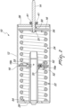
- the coupling system particularly for twin-spring assemblies designated generally by the reference numeral 10, comprises substantially a preferably cylindrical hollow body 12, a longitudinal guide 20 which is coaxial with respect to the preferably cylindrical hollow body 12, a sliding disk 18, a first spring 22 and a second spring 24 which are fixed to the ends of the sliding disk 18, a compression disk 16 arranged within the preferably cylindrical hollow body 12, and a stem 14, which is fixed to the compression disk 16 and passes through a hole 30 that is present in the distal wall 26.
- the preferably cylindrical hollow body 12 is the element that constitutes the load-bearing structure of the coupling system 10.
- the preferably cylindrical hollow body 12 is made of metallic material, such as for example steel or aluminum.
- a proximal wall 28 and a distal wall 26 are fixed to the ends of the preferably cylindrical hollow body 12 and both are preferably made of metallic material, such as for example steel or aluminum. In one embodiment of the invention, these ends have a flat and circular shape, with such a diameter that their outer edge corresponds to the edge of the ends of the preferably cylindrical hollow body 12.
- the proximal wall 28 comprises fixing means 54 adapted to fix the proximal wall 28 to an end of the first spring 22.
- the proximal wall 28 also has the task of stopping the motion of the two springs 22, 24 arranged in series, constituting the mechanical stroke limiting abutment of the coupling system 10.
- the distal wall 26 comprises a hole 30 adapted for the passage of a stem 14.
- the distal wall 26 further comprises locking means 41 configured for locking the coupling system 10 to the supports that are present on the machine for which it is intended, such as for example a pneumatically actuated actuator.
- the locking means 41 comprised in the coupling system 10 can be constituted for example by screws, bolts or nuts arranged on the outer surface of the distal wall 26.
- the longitudinal guide 20 comprises a first end 38 which is fixed to the proximal wall 28 of the preferably cylindrical hollow body 12.
- the longitudinal guide has a hollow cylindrical shape and is conveniently arranged along the longitudinal axis of the preferably cylindrical hollow body 12.
- the longitudinal guide 20 allows the sliding of the movement means 33 comprised within the sliding disk 18.
- the sliding disk 18 comprises at least one pin 52 which is adapted to fix a first end 18a of the sliding disk 18 to one end of the first spring 22.
- the sliding disk 18 further comprises a sliding assembly which comprises at least two movement means 33.
- the movement means 33 are configured to allow the movement of the sliding disk 18 along the longitudinal guide 20.
- the movement means 33 are conveniently coupled to the sliding disk 18. In one embodiment of the invention, the movement means 33 allow a movement of the sliding disk 18 along the longitudinal guide 20 with minimal friction force.
- the movement means 33 comprise a frame 44 which is conveniently coupled to the sliding disk 18 by way of at least two pivots 46 and at least one screw 48.
- the frame 44 accommodates a roller 42 which is conveniently fixed to the frame 44 by means of a longitudinal bar 50.
- the roller 42 is adapted to rotate about the longitudinal bar 50.
- the sliding disk 18 comprises at least one pin 52 which is adapted to fix a second end 18b of the sliding disk 18 to one end of the second spring 24.
- the pins 52 couple the ends of the two springs 22, 24 arranged in series to the two ends of the sliding disk 18. This coupling allows to reduce to a minimum the flexibility of the ends of the two springs in case of motion thereof (compression and/or decompression).
- the pins 52 allow to maintain an alignment between the first spring 22 and the second spring 24 comprised within the preferably cylindrical hollow body 12.
- the first spring 22 comprises an end coupled to the proximal wall 28 and an end coupled to a first end 18a of the sliding disk 18.
- the first spring 22 is preferably a helical compression and traction spring.
- the second spring 24 comprises an end coupled to the compression disk 16 and an end coupled to a second end 18b of the sliding disk 18.
- the second spring 24 is preferably a helical compression and traction spring.
- the compression disk 16 preferably made of metallic material, such as for example steel or aluminum, is arranged within the preferably cylindrical hollow body 12, at right angles to the longitudinal axis of the preferably cylindrical hollow body 12 proper.
- the compression disk 16 has a flat and circular shape, with such a diameter that its outer edge corresponds to the internal surface of the preferably cylindrical hollow body 12.
- the compression disk 16 is arranged proximate to the distal wall 26 and has furthermore a hole 31 for the fixing of the stem 14.
- the stem 14 is a stem of the simple type and is constituted by a bar preferably made of metallic material, such as for example steel or aluminum.
- the stem 14 is coaxial to the preferably cylindrical hollow body 12 and is perpendicular to the compression disk 16.
- One end of the stem 14 is inserted in the hole 31 of the compression disk 16.
- the stem 14 furthermore passes through the hole 30 that is present in the distal wall 26.
- the second spring 24 then begins to be compressed and transmits the linear motion to the first spring 22 by means of the sliding disk 18, the latter being coupled to the ends of both springs by means of the pins 52.
- the sliding disk 18 slides along the longitudinal guide 20 toward the proximal wall 28 by way of the movement means 33, such as for example rollers, and the first spring 22 begins to be compressed due to the thrust that it has received.
- the movement of the sliding disk 18 stops when the sliding disk 18 is proximate to the proximal wall 28 and accordingly the compression disk 16 is proximate to the second end 40 of the longitudinal guide 20.
- the inactive state or initial state of the coupling system 10 is reached as a consequence of the decompression of the two springs 22, 24 arranged in series.
- the first spring 22 begins to decompress and transmits the linear motion to the second spring 24 by way of the sliding disk 18.
- the sliding disk 18 slides along the longitudinal guide 20 toward the distal wall 26 by way of the movement means 33, such as for example rollers, and the second spring 24 begins to decompress.
- the sliding disk 18 and the compression disk 16 thus return to their initial positions and the two springs 22, 24 arranged in series are in inactive conditions.
- Another advantage of the coupling system particularly for twin-spring modules according to the invention resides in that it allows a movement of a sliding disk along a longitudinal guide with minimal friction force.
- a further advantage of the coupling system particularly for twin-spring modules according to the invention resides in that it allows minimal flexibility between the two ends of the two springs arranged on the two ends of the sliding disk.
- Another advantage of the coupling system particularly for twin-spring modules according to the invention resides in that it allows to reduce the structural problems of systems of the known type.
- the materials used may be any according to requirements and to the state of the art.
Landscapes
- Engineering & Computer Science (AREA)
- General Engineering & Computer Science (AREA)
- Mechanical Engineering (AREA)
- Springs (AREA)
- Buildings Adapted To Withstand Abnormal External Influences (AREA)
Claims (10)
- Ein Kupplungssystem (10), insbesondere für Doppelfedermodule, das einen Hohlkörper (12) umfasst, der ausgebildet ist, um eine erste Feder (22) und eine zweite Feder (24) aufzunehmen, wobei der Hohlkörper (12) eine Gleitscheibe (18) umfasst, angeordnet zwischen der ersten Feder (22) und der zweiten Feder (24), eine Druckscheibe (16), angeordnet in der Nähe einer distalen Wand (26) des Hohlkörpers (12), und eine längliche Führung (20), die koaxial mit dem Hohlkörper (12) ist; wobei die Gleitscheibe (18) ausgebildet ist, um eine Ausrichtung zwischen der ersten Feder (22) und der zweiten Feder (24) aufrechtzuerhalten und eine Bewegung der Gleitscheibe (18) entlang der länglichen Führung (20) zu ermöglichen, wobei die Gleitscheibe (18) entlang der länglichen Führung (20) mit Hilfe eines Gleitaufbaus gleitet, der mindestens zwei Bewegungsmittel (33) umfasst; dadurch gekennzeichnet, dass jedes Bewegungsmittel (33) einen Rahmen (44) umfasst, der mit der Gleitscheibe (18) über mindestens zwei Drehzapfen (46) und mindestens eine Schraube (48) gekoppelt ist; wobei der Rahmen (44) eine Walze (42) enthält, die über einen Längsstift (50) am Rahmen (44) befestigt ist; wobei die Walze (42) ausgebildet ist, um sich um den Längsstift (50) zu drehen.
- Das Kupplungssystem (10), insbesondere für Doppelfedermodule, gemäß Anspruch 1, dadurch gekennzeichnet, dass ein erstes Ende (38) der Längsführung (20) mit einer proximalen Wand (28) des Hohlkörpers (12) gekoppelt ist.
- Das Kupplungssystem (10), insbesondere für Doppelfedermodule, gemäß Anspruch 1, dadurch gekennzeichnet, dass die Druckscheibe (16) über ein Loch (31) in der Druckscheibe (16) mit einem Schaft (14) gekoppelt ist.
- Das Kupplungssystem (10), insbesondere für Doppelfedermodule, gemäß Anspruch 3, dadurch gekennzeichnet, dass der Schaft (14) durch ein Loch (30) in einer distalen Wand (26) des Hohlkörpers (12) verläuft.
- Das Kupplungssystem (10), insbesondere für Doppelfedermodule, gemäß einem beliebigen der obigen Ansprüche, dadurch gekennzeichnet, dass die Bewegungsmittel (33), die in dem Gleitaufbau umfasst sind, mit der in dem Hohlkörper (12) umfassten Gleitscheibe (18) gekoppelt sind.
- Das Kupplungssystem (10), insbesondere für Doppelfedermodule, gemäß einem beliebigen der obigen Ansprüche, dadurch gekennzeichnet, dass die distale Wand (26) und/oder die proximale Wand (28) Verriegelungsmittel (41) umfassen.
- Das Kupplungssystem (10), insbesondere für Doppelfedermodule, gemäß einem beliebigen der obigen Ansprüche, dadurch gekennzeichnet, dass die erste Feder (22) mit der Gleitscheibe (18) über mindestens einen Stift (52) gekoppelt ist.
- Das Kupplungssystem (10), insbesondere für Doppelfedermodule, gemäß einem beliebigen der obigen Ansprüche, dadurch gekennzeichnet, dass die zweite Feder (24) mit der Gleitscheibe (18) über mindestens einen Stift (52) gekoppelt ist.
- Das Kupplungssystem (10), insbesondere für Doppelfedermodule, gemäß einem beliebigen der obigen Ansprüche, dadurch gekennzeichnet, dass die erste Feder (22) mit der proximalen Wand (28) über mindestens ein Befestigungsmittel (54) gekoppelt ist.
- Das Kupplungssystem (10), insbesondere für Doppelfedermodule, gemäß einem beliebigen der obigen Ansprüche, dadurch gekennzeichnet, dass die zweite Feder (24) mit der Druckscheibe (16) über mindestens ein Befestigungsmittel (54) gekoppelt ist.
Applications Claiming Priority (2)
| Application Number | Priority Date | Filing Date | Title |
|---|---|---|---|
| IT102017000077733A IT201700077733A1 (it) | 2017-07-11 | 2017-07-11 | Sistema di accoppiamento particolarmente per moduli Twin-Springs. |
| PCT/EP2018/068355 WO2019011799A1 (en) | 2017-07-11 | 2018-07-06 | COUPLING SYSTEM, IN PARTICULAR FOR TWO-SPRING MODULES |
Publications (2)
| Publication Number | Publication Date |
|---|---|
| EP3652460A1 EP3652460A1 (de) | 2020-05-20 |
| EP3652460B1 true EP3652460B1 (de) | 2025-05-14 |
Family
ID=60570028
Family Applications (1)
| Application Number | Title | Priority Date | Filing Date |
|---|---|---|---|
| EP18737271.9A Active EP3652460B1 (de) | 2017-07-11 | 2018-07-06 | Kupplungssystem, insbesondere für doppelfedermodule |
Country Status (4)
| Country | Link |
|---|---|
| EP (1) | EP3652460B1 (de) |
| ES (1) | ES3036502T3 (de) |
| IT (1) | IT201700077733A1 (de) |
| WO (1) | WO2019011799A1 (de) |
Families Citing this family (1)
| Publication number | Priority date | Publication date | Assignee | Title |
|---|---|---|---|---|
| JP6725580B2 (ja) * | 2018-04-24 | 2020-07-22 | ファナック株式会社 | ロボット用重力バランサおよびロボット |
Family Cites Families (5)
| Publication number | Priority date | Publication date | Assignee | Title |
|---|---|---|---|---|
| GB545720A (en) * | 1941-07-15 | 1942-06-09 | Cyril James Fisher | Spring control device |
| DE7409850U (de) * | 1974-03-21 | 1974-06-27 | Gerb Gesellschaft Fuer Isolierung Mbh & Co Kg | Federkörper mit übereinander angeordneten Federn |
| JPS63210401A (ja) * | 1987-02-23 | 1988-09-01 | Toyota Motor Corp | アキュムレ−タ |
| US6336626B1 (en) * | 1999-07-19 | 2002-01-08 | Moonraker Farm, Inc. | Stirrup suspension |
| US7744062B2 (en) * | 2007-03-09 | 2010-06-29 | Fisher Controls International Llc | Apparatus to vary effective spring rate for use in diaphragm actuators |
-
2017
- 2017-07-11 IT IT102017000077733A patent/IT201700077733A1/it unknown
-
2018
- 2018-07-06 WO PCT/EP2018/068355 patent/WO2019011799A1/en not_active Ceased
- 2018-07-06 EP EP18737271.9A patent/EP3652460B1/de active Active
- 2018-07-06 ES ES18737271T patent/ES3036502T3/es active Active
Also Published As
| Publication number | Publication date |
|---|---|
| ES3036502T3 (en) | 2025-09-19 |
| EP3652460A1 (de) | 2020-05-20 |
| WO2019011799A1 (en) | 2019-01-17 |
| IT201700077733A1 (it) | 2019-01-11 |
Similar Documents
| Publication | Publication Date | Title |
|---|---|---|
| US9644384B2 (en) | Buckling restrained brace and related methods | |
| RU164701U1 (ru) | Фрикционный амортизатор | |
| US7766392B2 (en) | Articulate connection piece for tubes | |
| DE102020210860A1 (de) | Mehrteilige Feder für eine Kugelumlaufspindel | |
| EP3652460B1 (de) | Kupplungssystem, insbesondere für doppelfedermodule | |
| US10253837B2 (en) | Sacrificial energy dissipation mechanism | |
| US11719323B2 (en) | Worm drive | |
| KR101357956B1 (ko) | 작업차 | |
| US9631646B2 (en) | Cylinder mechanism | |
| DE2945640A1 (de) | Vorrichtung zum abstuetzen einer rohrleitung | |
| EP3718384B1 (de) | Tiefwassertauchsystem | |
| WO2020021027A1 (en) | Actuator with snubber assembly | |
| EP2910804B1 (de) | Linearführungssystem mit Überlastsicherung | |
| US3719255A (en) | Energy absorbing device | |
| US4537388A (en) | Adjustable tensioning device | |
| US12078293B2 (en) | Tank comprising inner and outer chambers and at least one link system with flexible radial blades linking said chambers | |
| US20160102725A1 (en) | Energy absorber | |
| US20250251031A1 (en) | System with variable stiffness | |
| CA2451710A1 (en) | Method and apparatus for coupling wall panels of a building | |
| Wang et al. | Experimental behavior, hysteretic model, and finite-element analysis of a low-prestressed self-centering friction dissipative brace | |
| US11255099B2 (en) | Steel plate damper for structures subject to dynamic loading | |
| CN113984426A (zh) | 一种舵机弹性负载 | |
| JP2024053399A (ja) | 屈曲構造体及びその半製品 | |
| US20080258363A1 (en) | Mechanical Control Shock-Absorbent Anti-Recoil Universal Mechanism | |
| CN110374222B (zh) | 一种自复位阻尼器 |
Legal Events
| Date | Code | Title | Description |
|---|---|---|---|
| STAA | Information on the status of an ep patent application or granted ep patent |
Free format text: STATUS: UNKNOWN |
|
| STAA | Information on the status of an ep patent application or granted ep patent |
Free format text: STATUS: THE INTERNATIONAL PUBLICATION HAS BEEN MADE |
|
| PUAI | Public reference made under article 153(3) epc to a published international application that has entered the european phase |
Free format text: ORIGINAL CODE: 0009012 |
|
| STAA | Information on the status of an ep patent application or granted ep patent |
Free format text: STATUS: REQUEST FOR EXAMINATION WAS MADE |
|
| 17P | Request for examination filed |
Effective date: 20200129 |
|
| AK | Designated contracting states |
Kind code of ref document: A1 Designated state(s): AL AT BE BG CH CY CZ DE DK EE ES FI FR GB GR HR HU IE IS IT LI LT LU LV MC MK MT NL NO PL PT RO RS SE SI SK SM TR |
|
| AX | Request for extension of the european patent |
Extension state: BA ME |
|
| DAV | Request for validation of the european patent (deleted) | ||
| DAX | Request for extension of the european patent (deleted) | ||
| STAA | Information on the status of an ep patent application or granted ep patent |
Free format text: STATUS: EXAMINATION IS IN PROGRESS |
|
| 17Q | First examination report despatched |
Effective date: 20220525 |
|
| P01 | Opt-out of the competence of the unified patent court (upc) registered |
Effective date: 20230527 |
|
| GRAP | Despatch of communication of intention to grant a patent |
Free format text: ORIGINAL CODE: EPIDOSNIGR1 |
|
| STAA | Information on the status of an ep patent application or granted ep patent |
Free format text: STATUS: GRANT OF PATENT IS INTENDED |
|
| INTG | Intention to grant announced |
Effective date: 20241205 |
|
| GRAS | Grant fee paid |
Free format text: ORIGINAL CODE: EPIDOSNIGR3 |
|
| GRAA | (expected) grant |
Free format text: ORIGINAL CODE: 0009210 |
|
| STAA | Information on the status of an ep patent application or granted ep patent |
Free format text: STATUS: THE PATENT HAS BEEN GRANTED |
|
| AK | Designated contracting states |
Kind code of ref document: B1 Designated state(s): AL AT BE BG CH CY CZ DE DK EE ES FI FR GB GR HR HU IE IS IT LI LT LU LV MC MK MT NL NO PL PT RO RS SE SI SK SM TR |
|
| REG | Reference to a national code |
Ref country code: GB Ref legal event code: FG4D |
|
| REG | Reference to a national code |
Ref country code: CH Ref legal event code: EP |
|
| REG | Reference to a national code |
Ref country code: IE Ref legal event code: FG4D |
|
| REG | Reference to a national code |
Ref country code: DE Ref legal event code: R096 Ref document number: 602018081916 Country of ref document: DE |
|
| PGFP | Annual fee paid to national office [announced via postgrant information from national office to epo] |
Ref country code: GB Payment date: 20250620 Year of fee payment: 8 |
|
| REG | Reference to a national code |
Ref country code: NL Ref legal event code: MP Effective date: 20250514 |
|
| REG | Reference to a national code |
Ref country code: ES Ref legal event code: FG2A Ref document number: 3036502 Country of ref document: ES Kind code of ref document: T3 Effective date: 20250919 |
|
| PG25 | Lapsed in a contracting state [announced via postgrant information from national office to epo] |
Ref country code: PT Free format text: LAPSE BECAUSE OF FAILURE TO SUBMIT A TRANSLATION OF THE DESCRIPTION OR TO PAY THE FEE WITHIN THE PRESCRIBED TIME-LIMIT Effective date: 20250915 Ref country code: FI Free format text: LAPSE BECAUSE OF FAILURE TO SUBMIT A TRANSLATION OF THE DESCRIPTION OR TO PAY THE FEE WITHIN THE PRESCRIBED TIME-LIMIT Effective date: 20250514 |
|
| PGFP | Annual fee paid to national office [announced via postgrant information from national office to epo] |
Ref country code: ES Payment date: 20250805 Year of fee payment: 8 |
|
| PGFP | Annual fee paid to national office [announced via postgrant information from national office to epo] |
Ref country code: DE Payment date: 20250714 Year of fee payment: 8 |
|
| REG | Reference to a national code |
Ref country code: LT Ref legal event code: MG9D |
|
| PG25 | Lapsed in a contracting state [announced via postgrant information from national office to epo] |
Ref country code: GR Free format text: LAPSE BECAUSE OF FAILURE TO SUBMIT A TRANSLATION OF THE DESCRIPTION OR TO PAY THE FEE WITHIN THE PRESCRIBED TIME-LIMIT Effective date: 20250815 Ref country code: NO Free format text: LAPSE BECAUSE OF FAILURE TO SUBMIT A TRANSLATION OF THE DESCRIPTION OR TO PAY THE FEE WITHIN THE PRESCRIBED TIME-LIMIT Effective date: 20250814 |
|
| PG25 | Lapsed in a contracting state [announced via postgrant information from national office to epo] |
Ref country code: PL Free format text: LAPSE BECAUSE OF FAILURE TO SUBMIT A TRANSLATION OF THE DESCRIPTION OR TO PAY THE FEE WITHIN THE PRESCRIBED TIME-LIMIT Effective date: 20250514 Ref country code: NL Free format text: LAPSE BECAUSE OF FAILURE TO SUBMIT A TRANSLATION OF THE DESCRIPTION OR TO PAY THE FEE WITHIN THE PRESCRIBED TIME-LIMIT Effective date: 20250514 |
|
| PGFP | Annual fee paid to national office [announced via postgrant information from national office to epo] |
Ref country code: IT Payment date: 20250811 Year of fee payment: 8 |
|
| REG | Reference to a national code |
Ref country code: AT Ref legal event code: MK05 Ref document number: 1794999 Country of ref document: AT Kind code of ref document: T Effective date: 20250514 |
|
| PG25 | Lapsed in a contracting state [announced via postgrant information from national office to epo] |
Ref country code: BG Free format text: LAPSE BECAUSE OF FAILURE TO SUBMIT A TRANSLATION OF THE DESCRIPTION OR TO PAY THE FEE WITHIN THE PRESCRIBED TIME-LIMIT Effective date: 20250514 |
|
| PG25 | Lapsed in a contracting state [announced via postgrant information from national office to epo] |
Ref country code: HR Free format text: LAPSE BECAUSE OF FAILURE TO SUBMIT A TRANSLATION OF THE DESCRIPTION OR TO PAY THE FEE WITHIN THE PRESCRIBED TIME-LIMIT Effective date: 20250514 |
|
| PG25 | Lapsed in a contracting state [announced via postgrant information from national office to epo] |
Ref country code: AT Free format text: LAPSE BECAUSE OF FAILURE TO SUBMIT A TRANSLATION OF THE DESCRIPTION OR TO PAY THE FEE WITHIN THE PRESCRIBED TIME-LIMIT Effective date: 20250514 |
|
| PG25 | Lapsed in a contracting state [announced via postgrant information from national office to epo] |
Ref country code: RS Free format text: LAPSE BECAUSE OF FAILURE TO SUBMIT A TRANSLATION OF THE DESCRIPTION OR TO PAY THE FEE WITHIN THE PRESCRIBED TIME-LIMIT Effective date: 20250814 |
|
| PG25 | Lapsed in a contracting state [announced via postgrant information from national office to epo] |
Ref country code: IS Free format text: LAPSE BECAUSE OF FAILURE TO SUBMIT A TRANSLATION OF THE DESCRIPTION OR TO PAY THE FEE WITHIN THE PRESCRIBED TIME-LIMIT Effective date: 20250914 |
|
| PG25 | Lapsed in a contracting state [announced via postgrant information from national office to epo] |
Ref country code: LV Free format text: LAPSE BECAUSE OF FAILURE TO SUBMIT A TRANSLATION OF THE DESCRIPTION OR TO PAY THE FEE WITHIN THE PRESCRIBED TIME-LIMIT Effective date: 20250514 |
|
| PG25 | Lapsed in a contracting state [announced via postgrant information from national office to epo] |
Ref country code: DK Free format text: LAPSE BECAUSE OF FAILURE TO SUBMIT A TRANSLATION OF THE DESCRIPTION OR TO PAY THE FEE WITHIN THE PRESCRIBED TIME-LIMIT Effective date: 20250514 Ref country code: SM Free format text: LAPSE BECAUSE OF FAILURE TO SUBMIT A TRANSLATION OF THE DESCRIPTION OR TO PAY THE FEE WITHIN THE PRESCRIBED TIME-LIMIT Effective date: 20250514 |
|
| PG25 | Lapsed in a contracting state [announced via postgrant information from national office to epo] |
Ref country code: CZ Free format text: LAPSE BECAUSE OF FAILURE TO SUBMIT A TRANSLATION OF THE DESCRIPTION OR TO PAY THE FEE WITHIN THE PRESCRIBED TIME-LIMIT Effective date: 20250514 |
|
| PG25 | Lapsed in a contracting state [announced via postgrant information from national office to epo] |
Ref country code: EE Free format text: LAPSE BECAUSE OF FAILURE TO SUBMIT A TRANSLATION OF THE DESCRIPTION OR TO PAY THE FEE WITHIN THE PRESCRIBED TIME-LIMIT Effective date: 20250514 |
|
| PG25 | Lapsed in a contracting state [announced via postgrant information from national office to epo] |
Ref country code: SK Free format text: LAPSE BECAUSE OF FAILURE TO SUBMIT A TRANSLATION OF THE DESCRIPTION OR TO PAY THE FEE WITHIN THE PRESCRIBED TIME-LIMIT Effective date: 20250514 Ref country code: RO Free format text: LAPSE BECAUSE OF FAILURE TO SUBMIT A TRANSLATION OF THE DESCRIPTION OR TO PAY THE FEE WITHIN THE PRESCRIBED TIME-LIMIT Effective date: 20250514 |
|
| REG | Reference to a national code |
Ref country code: DE Ref legal event code: R097 Ref document number: 602018081916 Country of ref document: DE |
|
| REG | Reference to a national code |
Ref country code: CH Ref legal event code: H13 Free format text: ST27 STATUS EVENT CODE: U-0-0-H10-H13 (AS PROVIDED BY THE NATIONAL OFFICE) Effective date: 20260224 |
|
| PG25 | Lapsed in a contracting state [announced via postgrant information from national office to epo] |
Ref country code: LU Free format text: LAPSE BECAUSE OF NON-PAYMENT OF DUE FEES Effective date: 20250706 |
|
| PLBE | No opposition filed within time limit |
Free format text: ORIGINAL CODE: 0009261 |
|
| STAA | Information on the status of an ep patent application or granted ep patent |
Free format text: STATUS: NO OPPOSITION FILED WITHIN TIME LIMIT |
|
| REG | Reference to a national code |
Ref country code: CH Ref legal event code: L10 Free format text: ST27 STATUS EVENT CODE: U-0-0-L10-L00 (AS PROVIDED BY THE NATIONAL OFFICE) Effective date: 20260325 |
|
| REG | Reference to a national code |
Ref country code: BE Ref legal event code: MM Effective date: 20250731 |
|
| PG25 | Lapsed in a contracting state [announced via postgrant information from national office to epo] |
Ref country code: BE Free format text: LAPSE BECAUSE OF NON-PAYMENT OF DUE FEES Effective date: 20250731 |
|
| PG25 | Lapsed in a contracting state [announced via postgrant information from national office to epo] |
Ref country code: FR Free format text: LAPSE BECAUSE OF NON-PAYMENT OF DUE FEES Effective date: 20250714 |
|
| 26N | No opposition filed |
Effective date: 20260217 |