EP3652519B1 - Procédé de surveillance de particules - Google Patents
Procédé de surveillance de particules Download PDFInfo
- Publication number
- EP3652519B1 EP3652519B1 EP18831463.7A EP18831463A EP3652519B1 EP 3652519 B1 EP3652519 B1 EP 3652519B1 EP 18831463 A EP18831463 A EP 18831463A EP 3652519 B1 EP3652519 B1 EP 3652519B1
- Authority
- EP
- European Patent Office
- Prior art keywords
- flow
- particle
- particles
- charger
- flow rate
- Prior art date
- Legal status (The legal status is an assumption and is not a legal conclusion. Google has not performed a legal analysis and makes no representation as to the accuracy of the status listed.)
- Active
Links
Images




Classifications
-
- B—PERFORMING OPERATIONS; TRANSPORTING
- B03—SEPARATION OF SOLID MATERIALS USING LIQUIDS OR USING PNEUMATIC TABLES OR JIGS; MAGNETIC OR ELECTROSTATIC SEPARATION OF SOLID MATERIALS FROM SOLID MATERIALS OR FLUIDS; SEPARATION BY HIGH-VOLTAGE ELECTRIC FIELDS
- B03C—MAGNETIC OR ELECTROSTATIC SEPARATION OF SOLID MATERIALS FROM SOLID MATERIALS OR FLUIDS; SEPARATION BY HIGH-VOLTAGE ELECTRIC FIELDS
- B03C3/00—Separating dispersed particles from gases or vapour, e.g. air, by electrostatic effect
- B03C3/017—Combinations of electrostatic separation with other processes, not otherwise provided for
-
- B—PERFORMING OPERATIONS; TRANSPORTING
- B03—SEPARATION OF SOLID MATERIALS USING LIQUIDS OR USING PNEUMATIC TABLES OR JIGS; MAGNETIC OR ELECTROSTATIC SEPARATION OF SOLID MATERIALS FROM SOLID MATERIALS OR FLUIDS; SEPARATION BY HIGH-VOLTAGE ELECTRIC FIELDS
- B03C—MAGNETIC OR ELECTROSTATIC SEPARATION OF SOLID MATERIALS FROM SOLID MATERIALS OR FLUIDS; SEPARATION BY HIGH-VOLTAGE ELECTRIC FIELDS
- B03C3/00—Separating dispersed particles from gases or vapour, e.g. air, by electrostatic effect
- B03C3/02—Plant or installations having external electricity supply
- B03C3/04—Plant or installations having external electricity supply dry type
- B03C3/06—Plant or installations having external electricity supply dry type characterised by presence of stationary tube electrodes
-
- B—PERFORMING OPERATIONS; TRANSPORTING
- B03—SEPARATION OF SOLID MATERIALS USING LIQUIDS OR USING PNEUMATIC TABLES OR JIGS; MAGNETIC OR ELECTROSTATIC SEPARATION OF SOLID MATERIALS FROM SOLID MATERIALS OR FLUIDS; SEPARATION BY HIGH-VOLTAGE ELECTRIC FIELDS
- B03C—MAGNETIC OR ELECTROSTATIC SEPARATION OF SOLID MATERIALS FROM SOLID MATERIALS OR FLUIDS; SEPARATION BY HIGH-VOLTAGE ELECTRIC FIELDS
- B03C3/00—Separating dispersed particles from gases or vapour, e.g. air, by electrostatic effect
- B03C3/02—Plant or installations having external electricity supply
- B03C3/04—Plant or installations having external electricity supply dry type
- B03C3/12—Plant or installations having external electricity supply dry type characterised by separation of ionising and collecting stations
-
- B—PERFORMING OPERATIONS; TRANSPORTING
- B03—SEPARATION OF SOLID MATERIALS USING LIQUIDS OR USING PNEUMATIC TABLES OR JIGS; MAGNETIC OR ELECTROSTATIC SEPARATION OF SOLID MATERIALS FROM SOLID MATERIALS OR FLUIDS; SEPARATION BY HIGH-VOLTAGE ELECTRIC FIELDS
- B03C—MAGNETIC OR ELECTROSTATIC SEPARATION OF SOLID MATERIALS FROM SOLID MATERIALS OR FLUIDS; SEPARATION BY HIGH-VOLTAGE ELECTRIC FIELDS
- B03C3/00—Separating dispersed particles from gases or vapour, e.g. air, by electrostatic effect
- B03C3/34—Constructional details or accessories or operation thereof
- B03C3/36—Controlling flow of gases or vapour
- B03C3/368—Controlling flow of gases or vapour by other than static mechanical means, e.g. internal ventilator or recycler
-
- B—PERFORMING OPERATIONS; TRANSPORTING
- B03—SEPARATION OF SOLID MATERIALS USING LIQUIDS OR USING PNEUMATIC TABLES OR JIGS; MAGNETIC OR ELECTROSTATIC SEPARATION OF SOLID MATERIALS FROM SOLID MATERIALS OR FLUIDS; SEPARATION BY HIGH-VOLTAGE ELECTRIC FIELDS
- B03C—MAGNETIC OR ELECTROSTATIC SEPARATION OF SOLID MATERIALS FROM SOLID MATERIALS OR FLUIDS; SEPARATION BY HIGH-VOLTAGE ELECTRIC FIELDS
- B03C3/00—Separating dispersed particles from gases or vapour, e.g. air, by electrostatic effect
- B03C3/34—Constructional details or accessories or operation thereof
- B03C3/40—Electrode constructions
- B03C3/41—Ionising-electrodes
-
- B—PERFORMING OPERATIONS; TRANSPORTING
- B03—SEPARATION OF SOLID MATERIALS USING LIQUIDS OR USING PNEUMATIC TABLES OR JIGS; MAGNETIC OR ELECTROSTATIC SEPARATION OF SOLID MATERIALS FROM SOLID MATERIALS OR FLUIDS; SEPARATION BY HIGH-VOLTAGE ELECTRIC FIELDS
- B03C—MAGNETIC OR ELECTROSTATIC SEPARATION OF SOLID MATERIALS FROM SOLID MATERIALS OR FLUIDS; SEPARATION BY HIGH-VOLTAGE ELECTRIC FIELDS
- B03C3/00—Separating dispersed particles from gases or vapour, e.g. air, by electrostatic effect
- B03C3/34—Constructional details or accessories or operation thereof
- B03C3/40—Electrode constructions
- B03C3/45—Collecting-electrodes
- B03C3/49—Collecting-electrodes tubular
-
- G—PHYSICS
- G01—MEASURING; TESTING
- G01N—INVESTIGATING OR ANALYSING MATERIALS BY DETERMINING THEIR CHEMICAL OR PHYSICAL PROPERTIES
- G01N15/00—Investigating characteristics of particles; Investigating permeability, pore-volume or surface-area of porous materials
- G01N15/06—Investigating concentration of particle suspensions
- G01N15/0656—Investigating concentration of particle suspensions using electric, e.g. electrostatic methods or magnetic methods
-
- B—PERFORMING OPERATIONS; TRANSPORTING
- B03—SEPARATION OF SOLID MATERIALS USING LIQUIDS OR USING PNEUMATIC TABLES OR JIGS; MAGNETIC OR ELECTROSTATIC SEPARATION OF SOLID MATERIALS FROM SOLID MATERIALS OR FLUIDS; SEPARATION BY HIGH-VOLTAGE ELECTRIC FIELDS
- B03C—MAGNETIC OR ELECTROSTATIC SEPARATION OF SOLID MATERIALS FROM SOLID MATERIALS OR FLUIDS; SEPARATION BY HIGH-VOLTAGE ELECTRIC FIELDS
- B03C2201/00—Details of magnetic or electrostatic separation
- B03C2201/06—Ionising electrode being a needle
-
- G—PHYSICS
- G01—MEASURING; TESTING
- G01N—INVESTIGATING OR ANALYSING MATERIALS BY DETERMINING THEIR CHEMICAL OR PHYSICAL PROPERTIES
- G01N15/00—Investigating characteristics of particles; Investigating permeability, pore-volume or surface-area of porous materials
- G01N2015/0042—Investigating dispersion of solids
- G01N2015/0046—Investigating dispersion of solids in gas, e.g. smoke
Definitions
- the invention relates to a method for measuring particle concentrations in an aerosol.
- An apparatus implementing such method is also disclosed.
- the method and the apparatus can be used in e.g. measuring ambient air quality or indoor air quality.
- Apparatus is preferably a particle sensor measuring particle mass concentration or particle number concentration or particle (active) surface area concentration or combination thereof. Apparatus can also be utilized in building sensor networks.
- Particles suspended in aerosols play a significant role in ambient and indoor air and in many technical processes.
- An important task lies in detecting the concentration of the particles by way of measurement technology.
- Particles in the size range of smaller than 10 micrometers diameter may be breathed in by humans and may have a detrimental effect on health.
- the most recent research results indicate that the usual protective functions of humans are no longer effective for nanoparticles ⁇ 100 nm in diameter.
- Nanoparticles arise mainly in combustion processes such as in motor vehicles, coal-fired power stations, wood heating installations, etc.
- Air Quality Index which combines the measurement results of different pollutants such as for instance nitrogen dioxide (NO2), ozone (O3) and particulate matter (PM).
- NO2 nitrogen dioxide
- O3 ozone
- PM particulate matter
- the combination method may differfrom one country to another.
- sensor networks Apart from the official air quality measurement sites, there is a growing interest towards sensor networks, which would provide supporting information on the air quality. In such networks the measured information, originated from many measurement nodes scattered over a large area, is collected and processed. As a result, spatially more accurate information is obtained, which could be used to follow the dispersion of pollutants from the emission sources and to support the localized air quality forecasts.
- Environmental Pollution, 2015, vol. 199, p.56-65 demonstrates a network of eight low-cost optical sensors for monitoring urban area particle concentrations.
- US 7,549,318 B1 (MATTER ENGINEERING), Jun.23, 2009 , describes a method and apparatus for measurement of the number concentration and of the average diameter of aerosol particles.
- Particles of an aerosol are firstly charged in a unipolar manner in a diffusion charger. They are subsequently led through a diffusional precipitator in which a part of the particles is precipitated. The diffusional precipitator current is measured and a value for the number concentration is evaluated from the current.
- a single diffusional precipitator may be used for this.
- a means for measuring the influence current and/or an aerosol electrometer are additionally present, by way of which one may measure a complete current. The latter additionally permits the evaluation of the average particle size.
- the simplest approach for electrical instrument consists of the following components: a diffusion charger, an ion collecting trap, a particle collecting filter inside a Faraday gage, an electrometer to measure the electric current and a pump to provide the sample flow.
- a diffusion charger an ion collecting trap
- a particle collecting filter inside a Faraday gage an electrometer to measure the electric current
- a pump to provide the sample flow.
- Document WO 2017/077190 A1 discloses an apparatus and process for measuring characteristics of a particle flow.
- Document ROSTEDT, ANTTI et al. “Modification of the ELP! to measure mean particle effective density in real-time", Journal of Aerosol Science, vol. 40, no. 9, September 2009 (2009-09), pages 823-831, Amsterdam, NL discloses a modification of electrical low pressure impactor (ELPI) for the particle effective density measurement.
- ELPI electrical low pressure impactor
- Document ROSTEDT, ANTTI et al. “Characterization and Response Model of the PPS-M Aerosol Sensor", Aerosol Science and Technology, vol. 48, no. 10, 14 August 2014 (2014-08-14), pages 1022-1030, USA discloses calibration results together with a comprehensive model for the response of the PPS-M sensor.
- Document US 2010/269600 A1 discloses a device for characterizing a size distribution of electrically-charged particles in an air flow.
- Document EP 2 853 882 A1 discloses a particle count measurement device.
- Document US 2004/080321 A1 discloses an apparatus for and method of analysing a mixture comprising a fluid and a plurality of electrically charged particles contained therein.
- Document US 2010/001 184 A1 discloses a miniaturized ultrafine particle sizer and monitor.
- the aim of the current invention is to introduce a method which solves at least some of the problems of the prior art, in which solution the response of apparatus is essentially independent on the sample flow rate.
- the method of the invention is characterized by the features of the independent method claim 1. Embodiments of the invention are disclosed in the dependent claims.
- the problem is thus non-expensive and reliable measurement of particle concentration, especially the measurement of ultrafine (less than 0,1 ⁇ m in diameter) particle concentration, in a fluctuating flow.
- Flow fluctuation may be rising from poor flow generator (like a fan which is sensitive to various parameters such as power voltage and current, changes in front and back pressures, soiling of blades, air density variation, air pressure variation, etc.
- the fluctuating flow may also arise from other fluctuating flows, like flow generated by wind or generated by propeller (like in drone, helicopter or airplane), ventilator, extractor, vacuum cleaner, chimney, exhaust tube, intake flow to combustion engine, other combustion system or ventilation channel or similar not originally meant for generating flow through a particle sensor but for some other purpose.
- other fluctuating flows like flow generated by wind or generated by propeller (like in drone, helicopter or airplane), ventilator, extractor, vacuum cleaner, chimney, exhaust tube, intake flow to combustion engine, other combustion system or ventilation channel or similar not originally meant for generating flow through a particle sensor but for some other purpose.
- the fluctuating flow may also be generated by a moving object, like balloon, airplane, helicopter, drone, sounding rocket, train, car, motorcycle, bicycle, roller board, boat, ship, horse or some other animal, or any other moving object.
- a moving object like balloon, airplane, helicopter, drone, sounding rocket, train, car, motorcycle, bicycle, roller board, boat, ship, horse or some other animal, or any other moving object.
- Information on the fluctuating flow received from an outside source like weather station or weather or air quality model (like Enfuser TM from Finnish Meteorological Institute, FMI) may be used to verify that the flow through the sensor is in operation range and/or to target the sensor to right direction.
- an outside source like weather station or weather or air quality model (like Enfuser TM from Finnish Meteorological Institute, FMI) may be used to verify that the flow through the sensor is in operation range and/or to target the sensor to right direction.
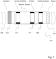
- FIG. 7 The main functional blocks of an apparatus are shown in Fig. 7 .
- the basic idea of an embodiment is to use the so called mobility analyzer (in this case a simple version called 0 th mobility analyzer by Tammet, H. F., 1970. The aspiration method for the determination of atmospheric-ion spectra, Israel Program of Scientific Translations, Jerusalem, 1970 ).
- the idea is to measure the collected current and use it alone as the measurement result indicating the particle concentration. It's important to find out that only a part of the current carried by charged particles are collected and measured, which is in fact against normal practice related to electrical particle monitors.
- the particle size dependent response function ( R s ) of apparatus based on particle charging and measurement, by a mobility analyzer, of the electrical current carried by electrically charged particles, gives the measured current for a given particle number concentration, in units of Am 3 or, as below fAcm 3 .
- the response is the product of the charging efficiency E ch (fAcm 3 ) and the collection efficiency of the mobility analyzer ⁇ ma (dimensionless) as shown in Equation 1.
- R s d p E ch d p ⁇ ma d p
- the response function R s may also be called as response function of the mobility analyzer R ma .
- Q 0 is a constant, dependent on the charger design. The value of this function starts from zero at zero flow rate and approaches unity at high flow rates.
- the number of elementary charges per particle depends on the product of the residence time and ion concentration in the charger ( N i t -product, see e.g. DAVIDSON et. Unipolar Charging of Ultrafine Particles by Diffusion of Ions: Theory and Experiment. In: Langmuir, 1985, Vol. 1, p. 150-158 ).
- the N i t -product of the charger decreases with increasing sample flow rate, which leads to decreased particle charging.
- a and B are constants dependent on the charged design. This is a decreasing function as a function of flow rate.
- the product P ch n 2 behaves as a function of flow rate as follows: starting from zero flow rate, the product P ch n 2 increases from low values, goes through a maximum and then decreases with increasing flow rate. At the flow rate value producing the maximum, the derivative of the product with respect to flow rate is zero. Within a range of flow rate values close to this value, the product and the response of the whole instrument become independent on the sample flow rate. Compared to the state of the art where P ch n is maximized to optimize sensitivity of an analyzer, optimization for response independence to sample flow is thus surprisingly achieved by maximizing P ch n 2 .
- the invention is based on insights that
- the flow may be generated by movement of means where apparatus using the method is attached.
- Such moving means may be any moving vehicle, e.g. car, bus, airplane, train, ship, balloon or unmanned aerial vehicle.
- the apparatus based on the method can also be used in applications where apparatus is essentially stationary but air moves around it such as inside a ventilation channel or in any flow generated by chimney effect.
- the method may also be used in situations where both mechanisms are used for flow generation, such as in cases when air propeller enhances the flow generated by moving means.
- the method can be used to monitor particle concentrations in different applications, such as monitoring indoor air quality, ambient air quality and particle emissions.
- the invented method comprises measuring or monitoring the content of particulate matter in a flowing gas stream.
- electrical particle charging is used to charge at least some of the particles in sample flow taken into the measurement apparatus.
- the electrical current carried by at least some of the charged particles is measured, and thus that is the response of the method.
- Typical feature of the method is that it can measure the content of particulate matter within +/-10% accuracy when the volumetric flow through the measuring or monitoring apparatus which is measuring or monitoring particulate content in the flowing gas stream has a dynamic range of 10, i.e. with nominal flow, Q sample or Q s , is 1, the flow range is 0.3-3.
- the term "accuracy" has here the meaning that when the particle concentration is measured with a certain volumetric flow inside the mentioned dynamic range, the same concentration in the sample flow is measured within +/-10% value from the first measurement with another volumetric flow within the same dynamic range.
- Nominal flow can change widely depending on the sensor design. The tests were mainly carried out by nominal flow of 5 litres per minutes, but the nominal flow can be e.g. 0.5, 50, 500 or 5000 litres per minute as well. Such conditions are achieved e.g. by designing the essential operational parameters, like nominal sample flow through the filter and/or ion production in the electrical charger and constructing the apparatus (e.g.
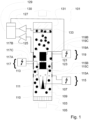
- FIG. 1 shows as an example a schematic drawing of one embodiment.
- Apparatus 101 is used for measuring or monitoring particles 109 in sample flow 105.
- Apparatus 101 comprises means 103 for driving flow 105 into apparatus 101.
- these means 103 can be called sample intake which may be a conventional tube or specially designed intake nozzle, various nozzle types being familiar to a person skilled in the art.
- Means 103 may also comprise functional elements to treat the sample flow, such as heating it (especially with ambient air measurements), removing volatile elements, such as water from the flow, neutralizing or charging the particles in the flow, etc.
- means 103 may comprise means for active flow generation such as a blower but if active flow generation is required it is typically realized by means 131 placed downstream of electrical charger 115 and particle analyzer.
- Apparatus 101 further comprises means 115 for electrically charging particles 109 to become electrically charged particles 123 by ions 113 produced by charger 115.
- the flow dependency of charging efficiency E ch (Q) is a parameter important for the operation of the invented method and apparatus.
- the method and apparatus may comprise method and means for controlling the charging efficiency E ch , although this is not shown in Fig. 1 .
- Apparatus 101 further comprises means 117 for removing the free ions 113 which are not attached to particles 109 before the electrical charge carried by at least a fraction of charged particles 123 is measured.
- the free ion removing means 117 is an electrical precipitator comprising voltage source 117A and ion trap created by electrical field between electrodes 117B and 117C. Ion trap can, however, be based on other mechanisms collecting free ions 113, e.g. due to their higher diffusion coefficient as compared to particles 109 and charged particles 123. If required, the electrical current generated to the collecting surface by free ions attaching on it may also be measured.
- Apparatus 101 further comprises means 119 for collecting a fraction of charged particles 123.
- the electrical current generated by the collected electrical charge on the fraction of collected electrically charged particles 123 is measured by means 125, typically by an electrometer.
- Fig. 1 shows the collection method for a fraction of charged particles to be an electrostatic precipitator but it may as well be any device based on particle properties such as a diffusion-based collector combined to electrical charge monitoring means 125.
- Apparatus 101 further comprises means 127 for measuring electrical current/charge carried by essentially all charged particles 123. Such measurement may be based on collecting essentially all charged particles 123 on a conductive filter 133 and measuring the charge collected on filter 133 by means 127 (on other words measuring the electrical current generated by collected charge with an electrometer). The total electrical charge/current measurement may also be based e.g. on measuring the escaping current as described in e.g. EP 2 247 939 B1 (PEGASOR), 22.04.2015 . The same patent describes a way to generate the intake flow by using an ejector which may be applied with the current invention.
- Apparatus 101 further comprises means 129 for comparing the electrical charge 125 detected in the means 119 collecting a fraction of charged particles 123 to electrical charge 127 generated by essentially all charged particles 123 and means 130 which are connected to the comparison means 129 and which are used to control collecting means 119 so that collecting means 119 collects less than a certain fraction of electrically charged particles 123.
- collecting means 119 is an electrostatic precipitator
- collection efficiency can be controlled by adjusting the electrical field strength generated by voltage source 119A and electrodes 119B and 119C, which generate the electrical field between them, of the electrical precipitator 119.
- collections means are e.g. a diffusion-based collector
- the collection efficiency can be adjusted by adjusting volumetric flow through the collector (note that excess clean air flows can be used in addition to the sample flow) or by adjusting the physical parameters of the diffusion-based collector such as the surface area or the length of the collector.
- Apparatus 101 may also comprise means 110 for separating charger mechanically from the particle-polluted sample flow 105 flowing inside the outer wall 107 of apparatus 101.
- Grid 111 ensures in this case ion 113 flow from charger to particles 109.
- the atmosphere inside separating means 110 may be different from atmosphere inside apparatus 101. This may be actively generated by e.g. directing essentially pure air or other suitable gas inside separating means 110 and generating positive pressure inside means
- Free ion remover 115 is in one embodiment an electrostatic precipitator comprising preferably adjustable voltage source 115A and electrodes 115B and 115C between which electrical field is formed.
- free ion remover 115 and charged particle remover 119 are connected to the same central axis 121 of apparatus 101.
- Means 119 removing fraction of charged particles 123 comprises an electrostatic precipitator comprising preferably adjustable voltage source 119A and electrodes 119B and 119C between which electrical field is formed.
- Apparatus 101 can be constructed to be lightweight as there is no absolute need for means of generating flow 131.
- Apparatus 101 can be installed to a moving object/means such as car, train, ship, airplane or equivalent.
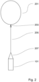
- Fig. 2 shows apparatus 101 being installed by fixing means 203, 205 and 207 to a balloon 201 and the essentially vertical movement of balloon 201 (either up or down) generates flow through apparatus 101.
- Flow through apparatus 101 can also be realized without means of generating flow 131 even if apparatus 101 is stationary.
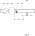
- Fig. 3 shows an embodiment where apparatus 101 is placed inside ventilation channel 309.
- ventilation channel there are basically three different measurement points: inlet (outdoor air), after the filters (purified air) and from the room (outlet, recirculation channel).
- Movement of intake air 303, generated by blower 305 and preferably filtered, heated or cooled by treatment unit 307 generates the necessary flow through apparatus 101 fixed into channel 309 by fixing means 311 and 313.
- the air from ventilation channel 309 is distributed through output terminals 315.
- One essential goal of the invention is to produce apparatus 101 which is low-cost and can thus be used in sensor networks.
- Such embodiment is shown in principle in Fig.4 where urban area 401, comprising e.g. residential building 403, streets 405, highways 407, parks 409 and factories 411 are measured by apparatus 101 distributed widely into the urban area 401.
- the measurement data from apparatuses 101 is preferably sent wirelessly into a cloud system and the data is analyzed and combined to provide a spatially accurate information in the air quality of the urban area.
- Such function can be carried out e.g. by Enfuser TM software developed by Finnish Meteorological Institute, FMI.
- Sensor network in urban area 101 may comprise various different pollutant sensors in addition to apparatus 101, such as sensors for pollutant gases (e.g. O 3 , SO x , NO x ), weather-related sensors (rainfall, wind direction, wind speed), noise sensors, traffic density sensors, etc.
- pollutant gases e.g. O 3 , SO x ,
- apparatus 101 can be fixed e.g. to measurement pod show in Fig.5 , 501.
- Bar 503 is fixed to ground 513 and apparatus 101 is fixed to bar 503 via fixing means 505 and 507.
- Flow intake means 103 of apparatus 101 may comprise heater 515 to heat sample flow 105 to 10-40 ° C higher than the ambient temperature.
- the measured signal is sent to a wireless unit 509 via cable 511 and sent wirelessly e.g. to cloud server.
- Apparatus 101 can further be used in indoor air measurement 601, shown in Fig. 6 .
- Apparatus 101 is fixed to indoor area which is surrounded e.g. by wall 603, door 605 and window 609.
- Apparatus 101 is connected to display unit 607 either by cable 611 or wirelessly.
- Apparatus 101 and display 607 may be installed away from each other.
- the measurement signal can also be sent to a cloud system from which the raw or analyzed/synthesized data can be sent to a separate display unit, like tablet, mobile phone or equivalent.
- the sensitivity of the response function R to flow rate Q was tested with polydisperse laboratory test aerosol using different sample flow rates in the range of 10 - 60 liters per minute (lpm).
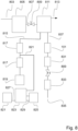
- the used measurement setup is shown in figure 8 .
- DOS dioctyl sebacate
- the aerosol was generated to a mixing chamber 811 connected to aerosol generator via line 807 and valve 809.
- test aerosol size distribution median size ( d m ) was varied between 35 - 340 nm, while the geometric standard deviation (GSD) varied between 1.3 and 1.6.
- SMPS Scanning Mobility Particle Sizer Spectrometer
- DMA Differential Mobility Analyzer
- TSI Inc. Differential Mobility Analyzer
- a Water Condensation Particle Counter (WCPC) 819 model 3786 (TSI Inc.) connected to line 815 exiting from mixing chamber 811 was used to measure the total number concentration to improve the concentration measurement accuracy.
- two ejector dilutors 817 were used, one in front of the SMPS 817 and two in front of the WCPC 819.
- the corresponding dilution ratios were 8.2 for the SMPS and 78 for the WCPC.
- the sample flow through apparatus 101 was controlled in the manner as in the monodisperse response measurements.
- Apparatus 101 which was connected to mixing chamber 811 via line 837 was further connected to vacuum line 835 via filter 831, valve 809 and mass flow controller 833.
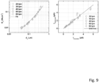
- Fig. 9 shows the measured and simulated test values.
- apparatus response in polydisperse test measurements is shown (both measured and fitted responses shown).
- the measured values are plotted as the function of the particle size representing the mean response over the number size distribution.
- the correlation plot between the simulated and measured apparatus outputs is shown.
- the response of apparatus 101 remains nearly independent on the sample flow rate in the range of 20 - 60 lpm.
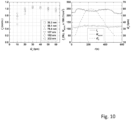
- Fig. 10 The flow rate independence of the measured response is further demonstrated in Fig. 10 .
- the normalized response of apparatus 101 is plotted against the sample flow rate for different particle size distributions. As seen on the left in Fig. 10 , the apparatus response remains nearly constant for the sample flow rate range from 20 lpm to 60 lpm.
- Fig. 10 is plotted the apparatus output and the measured number concentrations during a ramp in the sample flow rate. During the flow ramp, the aerosol generation was kept constant, however the median size decreasing steadily from 83 nm in the beginning to 79 nm at the end. This is seen as a slight change in the apparatus 101 signal when comparing the signal level in the beginning and the end of the flow ramp. Despite this, the apparatus 101 signal is staying within 10 % of the average level during the experiment.
- Fig. 11 Shows the calculated response function for one embodiment of the invention. It shows , with logarithmic scaling, that the accuracy of the equipment 101 is within +/-10% when the dynamic range of the equipment is 10, i.e. flow is 0.3 - 3 when the nominal flow is 1.
- the result of the invented method and apparatus is shown as response function curve of the equipment, R ma .
- Th other curve, R f shows the calculated response curve for a prior-art construction with particle charging and filter capture.
- the difference on the sensitivity of the response curve to flow rate Q sample has an outstanding difference between the prior-art and invented method.
- a particular embodiment had a nominal flow of 5 litres per minute and thus the flow range where the accuracy of equipment 101 was +/- 10% was 1.5 - 15 litres per minute.
- the given starting values for the sensor are the sample flow rate Qs, desired minimum particle size of interest Dp min, charger produced ion concentration starting value, Ni and residence time inside the charger, t, and weakly bound mobility analyzer voltage V ma .
- the volume flow is given, but in different applications, the available pressure difference or gas velocity may be given. In these cases the resulting volume flow may be iteratively computed or experimented.
- the ion exposure Nit is a best estimate for a corona charger in the middle of normal operating range.
- the length of the charger, hc is preferably the same. This sets the residence time in the desired value.
- the charger efficiency can be adjusted by reducing the charger voltage (decreasing losses) or by increasing the residence time by increasing the size of the charger.
- the maximum is above the set point (more than 2 of the nominal flow rate)
- opposite changes are effected to adjust the peak of the Pn 2 product to the nominal sample flow.
- the precision of the adjustment needs to be within 0.5 to 2 of the nominal sample flow to still fulfill the flow independence in flow range in similar flow range relative to nominal ( Fig 11 ).
- the charger voltage and diameter adjustments are not sufficient to reduce the P ch to appropriate level it is also possible to add an additional electrostatic ion trap, independently adjustable relative to the charger voltage.
- the adjustment of the voltage in relation to the peak of the Pn 2 product is the same as described for the charger voltage.
- the analyzer diameters are set, preferably such that the cross section of the sample passage is increased or kept the same.
- the inner diameter of the analyzer is two times the charger diameter and outer diameter of the analyzer four times the charger diameter.
Landscapes
- Chemical & Material Sciences (AREA)
- Dispersion Chemistry (AREA)
- Physics & Mathematics (AREA)
- Health & Medical Sciences (AREA)
- Life Sciences & Earth Sciences (AREA)
- Analytical Chemistry (AREA)
- Biochemistry (AREA)
- General Health & Medical Sciences (AREA)
- General Physics & Mathematics (AREA)
- Immunology (AREA)
- Pathology (AREA)
- Other Investigation Or Analysis Of Materials By Electrical Means (AREA)
Claims (4)
- Procédé pour mesurer ou surveiller la teneur en matières particulaires en suspension dans un gaz vecteur, échantillonné par débit volumique d'échantillon (Qs), le procédé comprenant la charge en particules électriques d'au moins certaines des particules dans le même écoulement d'échantillon, la collecte d'au moins certaines des particules chargées utilisant la force électrostatique dans le même écoulement d'échantillon et la mesure du courant électrique véhiculé par au moins certaines des particules chargées, caractérisé en ce que la charge et la collecte sont dimensionnées par maximisation de Pchn2, où Pch = pénétration des particules à travers le chargeur et n = nombre de charges élémentaires sur une particule, de façon que le courant véhiculé par les particules collectées soit mesuré et ledit courant ne constitue qu'une partie du courant total véhiculé par les particules chargées.
- Procédé selon la revendication 1, dans lequel la plage dynamique de l'équipement est de 10, c'est-à-dire que l'écoulement est de 0,3 à 3 fois l'écoulement nominal quand l'écoulement nominal est de 1.
- Procédé selon la revendication 1 ou 2, dans lequel la maximisation de Pchn2 à 0,5-2 du débit nominal (Qs) est effectuée par ajustement d'au moins l'un parmi la tension de charge rectificative et le temps de séjour rectificatif des particules dans le chargeur.
- Procédé selon l'une quelconque des revendications précédentes, dans lequel la mesure du courant électrique véhiculé par au moins certaines des particules chargées est effectué par un analyseur de mobilité.
Applications Claiming Priority (3)
| Application Number | Priority Date | Filing Date | Title |
|---|---|---|---|
| FI20177085 | 2017-07-14 | ||
| FI20187021 | 2018-02-12 | ||
| PCT/FI2018/050547 WO2019012185A1 (fr) | 2017-07-14 | 2018-07-13 | Procédé et appareil de surveillance de particules |
Publications (3)
| Publication Number | Publication Date |
|---|---|
| EP3652519A1 EP3652519A1 (fr) | 2020-05-20 |
| EP3652519A4 EP3652519A4 (fr) | 2021-04-14 |
| EP3652519B1 true EP3652519B1 (fr) | 2024-09-04 |
Family
ID=65001927
Family Applications (1)
| Application Number | Title | Priority Date | Filing Date |
|---|---|---|---|
| EP18831463.7A Active EP3652519B1 (fr) | 2017-07-14 | 2018-07-13 | Procédé de surveillance de particules |
Country Status (3)
| Country | Link |
|---|---|
| US (1) | US11703437B2 (fr) |
| EP (1) | EP3652519B1 (fr) |
| WO (1) | WO2019012185A1 (fr) |
Families Citing this family (10)
| Publication number | Priority date | Publication date | Assignee | Title |
|---|---|---|---|---|
| CN109945933A (zh) * | 2019-01-29 | 2019-06-28 | 深圳市白麓嵩天科技有限责任公司 | 一种粉尘流量检测方法及基于静电感应的粉尘流量检测装置 |
| WO2021023972A1 (fr) * | 2019-08-02 | 2021-02-11 | Cambridge Enterprise Limited | Capteur de particules et procédé de détection |
| FI129009B (en) | 2020-02-05 | 2021-05-14 | Dekati Oy | Method and device for monitoring the density of aerosol particles |
| DE102021116154A1 (de) | 2021-06-22 | 2022-12-22 | Ebm-Papst Mulfingen Gmbh & Co. Kg | Überwachungsvorrichtung und Verfahren zur Überwachung der Qualität einer Gasatmosphäre |
| CN113310858A (zh) * | 2021-06-24 | 2021-08-27 | 浙江浙能嘉华发电有限公司 | 浓度自适应调控的烟气雾滴粒径与浓度在线测量器及方法 |
| CN114408588A (zh) * | 2021-12-31 | 2022-04-29 | 成都瑞柯林工程技术有限公司 | 颗粒物气力输送检测方法及检测设备 |
| CN114314011B (zh) * | 2021-12-31 | 2024-07-26 | 成都瑞柯林工程技术有限公司 | 颗粒物回收装置 |
| US12540891B1 (en) * | 2022-01-24 | 2026-02-03 | Bluehalo, Llc | Method and apparatus for measuring extinction using an unmanned aerial vehicle |
| FI131726B1 (en) * | 2023-07-06 | 2025-10-20 | Pegasor Oy | Method and apparatus for measuring characteristics of a particle flow |
| CN118602549B (zh) * | 2024-06-17 | 2024-12-10 | 冠恒建设集团有限公司 | 洁净室的空气净化方法及洁净室离子控制系统 |
Family Cites Families (18)
| Publication number | Priority date | Publication date | Assignee | Title |
|---|---|---|---|---|
| US5350922A (en) * | 1993-03-22 | 1994-09-27 | Robert Bartz | Underwater light scattering sensor |
| US5922976A (en) * | 1995-10-12 | 1999-07-13 | California Institute Of Technology | Method of measuring aerosol particles using automated mobility-classified aerosol detector |
| DE69803184T2 (de) * | 1997-07-03 | 2009-09-24 | The Government of the United States of America, as represented by the Secretary Centers for Disease and Prevention, Office of Technology | Detektorröhre zum nachweisen von staub |
| AU2002337924A1 (en) * | 2001-10-22 | 2003-05-06 | Gideon Eden | Vehicle particulate analysis method and apparatus |
| US6965240B1 (en) * | 2002-04-01 | 2005-11-15 | The United States Of America As Represented By The Secretary Of The Department Of Health And Human Services | Apparatus and methods for analyzing particles using light-scattering sensors and ionization sensors |
| DE10242301A1 (de) | 2002-09-12 | 2004-03-18 | Robert Bosch Gmbh | Vorrichtung und Verfahren zur Messung der Konzentration von in einem strömenden Gas vorhandenen Partikeln |
| US6828794B2 (en) * | 2002-10-24 | 2004-12-07 | Cambustion Limited | Electrostatic particle measurement |
| EP1681550A1 (fr) | 2005-01-13 | 2006-07-19 | Matter Engineering AG | Procédé et dispositif pour la mesure de la concentration en nombre et du diamètre moyen de particules d'aérosol |
| US20080302666A1 (en) * | 2007-06-08 | 2008-12-11 | Benner W Henry | Apparatus for differential charged-particle mobility |
| US8044350B2 (en) | 2007-11-29 | 2011-10-25 | Washington University | Miniaturized ultrafine particle sizer and monitor |
| KR101540913B1 (ko) | 2007-12-12 | 2015-07-31 | 코닌클리케 필립스 엔.브이. | 공기 흐름 내의 전기적으로 충전된 공기 중 입자들의 크기 분포를 특징화하기 위한 장치 |
| FI20080182A0 (fi) | 2008-03-04 | 2008-03-04 | Navaro 245 Oy | Mittausmenetelmä ja -laite |
| CN101738429B (zh) | 2008-11-26 | 2013-04-03 | 岛津分析技术研发(上海)有限公司 | 离子分离、富集与检测装置 |
| US8038775B2 (en) * | 2009-04-24 | 2011-10-18 | Peter Gefter | Separating contaminants from gas ions in corona discharge ionizing bars |
| JP5817929B2 (ja) | 2012-05-21 | 2015-11-18 | 株式会社島津製作所 | 粒子数測定器 |
| US9791361B2 (en) | 2015-10-26 | 2017-10-17 | Dekati Oy | Method and apparatus for measuring aerosol particles of exhaust gas |
| WO2017077190A1 (fr) | 2015-11-02 | 2017-05-11 | Pegasor Oy | Appareil et procédé de mesure de caractéristiques de flux de particules |
| GB201609868D0 (en) | 2016-06-06 | 2016-07-20 | Cambridge Entpr Ltd | Particle measurement apparatus |
-
2018
- 2018-07-13 WO PCT/FI2018/050547 patent/WO2019012185A1/fr not_active Ceased
- 2018-07-13 EP EP18831463.7A patent/EP3652519B1/fr active Active
- 2018-07-13 US US16/629,857 patent/US11703437B2/en active Active
Also Published As
| Publication number | Publication date |
|---|---|
| EP3652519A1 (fr) | 2020-05-20 |
| WO2019012185A1 (fr) | 2019-01-17 |
| EP3652519A4 (fr) | 2021-04-14 |
| US20210140868A1 (en) | 2021-05-13 |
| US11703437B2 (en) | 2023-07-18 |
Similar Documents
| Publication | Publication Date | Title |
|---|---|---|
| EP3652519B1 (fr) | Procédé de surveillance de particules | |
| Järvinen et al. | Calibration of the new electrical low pressure impactor (ELPI+) | |
| EP2370802B1 (fr) | Capteur destiné à détecter des particules en suspension dans l'air | |
| Mirme et al. | A wide-range multi-channel Air lon Spectrometer. | |
| EP2853882B1 (fr) | Dispositif de mesure de comptage de particules | |
| KR101540914B1 (ko) | 공기 흐름 내에서 전기적으로 충전된 공기중 입자들의 크기 분포를 특성화하기 위한 디바이스 | |
| Morawska et al. | Effect of face velocity and the nature of aerosol on the collection of submicrometer particles by electrostatic precipitator | |
| Arffman et al. | High-resolution low-pressure cascade impactor | |
| US10760997B2 (en) | Apparatus and process for measuring characteristics of particle flow | |
| Kim et al. | MEMS-based particle detection system for measuring airborne ultrafine particles | |
| CN114199729A (zh) | 基于天然离子荷电测量大气气溶胶粒径分布的方法及系统 | |
| US20240344955A1 (en) | Reactive condensation particle counter for the detection of trace atmospheric gases | |
| CN213364532U (zh) | 一种基于颗粒物粒径精细分级的空气质量监测站 | |
| Laakkonen et al. | Effect of operation pressure on the response of ePNC particle number concentration sensor | |
| Hatoya et al. | On-line measurement of the surface area concentration of aerosols in Yokohama, Japan, using the diffusion charging method | |
| Li et al. | A miniature disk electrostatic aerosol classifier (mini-disk EAC) for personal nanoparticle sizers | |
| Morawska | Environmental aerosol physics | |
| Intra et al. | Performance evaluation of an electrometer system for ion and aerosol charge measurements | |
| Cleary | Measurements of the size distribution and aerodynamic properties of soot | |
| Williams | Construction and Validation of a DMPS for Aerosol Characterization | |
| Intra et al. | Performance Evaluation of a High-Precision Electrostatic PM2. 5 Monitoring System for Field Surveillance: Integration of Unipolar Diffusion Charging and Electrometric Detection | |
| Wei et al. | Penetration calibration and verification for the solid particle counting system with polydisperse and monodisperse particles | |
| Niemelä et al. | A novel method for particle sampling and size-classified electrical charge measurement at power plant environment | |
| Nene | Design of bioaerosol sampling inlets | |
| Schmidt‐Ott | New developments in aerosol characterization from the physical point of view |
Legal Events
| Date | Code | Title | Description |
|---|---|---|---|
| STAA | Information on the status of an ep patent application or granted ep patent |
Free format text: STATUS: THE INTERNATIONAL PUBLICATION HAS BEEN MADE |
|
| PUAI | Public reference made under article 153(3) epc to a published international application that has entered the european phase |
Free format text: ORIGINAL CODE: 0009012 |
|
| STAA | Information on the status of an ep patent application or granted ep patent |
Free format text: STATUS: REQUEST FOR EXAMINATION WAS MADE |
|
| 17P | Request for examination filed |
Effective date: 20200127 |
|
| AK | Designated contracting states |
Kind code of ref document: A1 Designated state(s): AL AT BE BG CH CY CZ DE DK EE ES FI FR GB GR HR HU IE IS IT LI LT LU LV MC MK MT NL NO PL PT RO RS SE SI SK SM TR |
|
| AX | Request for extension of the european patent |
Extension state: BA ME |
|
| DAV | Request for validation of the european patent (deleted) | ||
| DAX | Request for extension of the european patent (deleted) | ||
| A4 | Supplementary search report drawn up and despatched |
Effective date: 20210312 |
|
| RIC1 | Information provided on ipc code assigned before grant |
Ipc: G01N 15/06 20060101AFI20210308BHEP Ipc: G01N 1/22 20060101ALI20210308BHEP Ipc: G01N 15/02 20060101ALI20210308BHEP Ipc: B03C 3/00 20060101ALI20210308BHEP Ipc: B03C 3/06 20060101ALI20210308BHEP Ipc: B03C 3/12 20060101ALI20210308BHEP Ipc: B03C 3/41 20060101ALI20210308BHEP Ipc: B03C 3/49 20060101ALI20210308BHEP Ipc: G01N 15/00 20060101ALI20210308BHEP Ipc: B03C 3/017 20060101ALI20210308BHEP Ipc: B03C 3/36 20060101ALI20210308BHEP |
|
| STAA | Information on the status of an ep patent application or granted ep patent |
Free format text: STATUS: EXAMINATION IS IN PROGRESS |
|
| 17Q | First examination report despatched |
Effective date: 20230208 |
|
| GRAP | Despatch of communication of intention to grant a patent |
Free format text: ORIGINAL CODE: EPIDOSNIGR1 |
|
| STAA | Information on the status of an ep patent application or granted ep patent |
Free format text: STATUS: GRANT OF PATENT IS INTENDED |
|
| INTG | Intention to grant announced |
Effective date: 20240216 |
|
| GRAS | Grant fee paid |
Free format text: ORIGINAL CODE: EPIDOSNIGR3 |
|
| GRAA | (expected) grant |
Free format text: ORIGINAL CODE: 0009210 |
|
| STAA | Information on the status of an ep patent application or granted ep patent |
Free format text: STATUS: THE PATENT HAS BEEN GRANTED |
|
| AK | Designated contracting states |
Kind code of ref document: B1 Designated state(s): AL AT BE BG CH CY CZ DE DK EE ES FI FR GB GR HR HU IE IS IT LI LT LU LV MC MK MT NL NO PL PT RO RS SE SI SK SM TR |
|
| REG | Reference to a national code |
Ref country code: GB Ref legal event code: FG4D |
|
| REG | Reference to a national code |
Ref country code: CH Ref legal event code: EP |
|
| REG | Reference to a national code |
Ref country code: IE Ref legal event code: FG4D |
|
| REG | Reference to a national code |
Ref country code: DE Ref legal event code: R096 Ref document number: 602018074058 Country of ref document: DE |
|
| P01 | Opt-out of the competence of the unified patent court (upc) registered |
Free format text: CASE NUMBER: APP_61812/2024 Effective date: 20241119 |
|
| REG | Reference to a national code |
Ref country code: LT Ref legal event code: MG9D |
|
| REG | Reference to a national code |
Ref country code: NL Ref legal event code: MP Effective date: 20240904 |
|
| PG25 | Lapsed in a contracting state [announced via postgrant information from national office to epo] |
Ref country code: NO Free format text: LAPSE BECAUSE OF FAILURE TO SUBMIT A TRANSLATION OF THE DESCRIPTION OR TO PAY THE FEE WITHIN THE PRESCRIBED TIME-LIMIT Effective date: 20241204 |
|
| PG25 | Lapsed in a contracting state [announced via postgrant information from national office to epo] |
Ref country code: FI Free format text: LAPSE BECAUSE OF FAILURE TO SUBMIT A TRANSLATION OF THE DESCRIPTION OR TO PAY THE FEE WITHIN THE PRESCRIBED TIME-LIMIT Effective date: 20240904 Ref country code: GR Free format text: LAPSE BECAUSE OF FAILURE TO SUBMIT A TRANSLATION OF THE DESCRIPTION OR TO PAY THE FEE WITHIN THE PRESCRIBED TIME-LIMIT Effective date: 20241205 Ref country code: PL Free format text: LAPSE BECAUSE OF FAILURE TO SUBMIT A TRANSLATION OF THE DESCRIPTION OR TO PAY THE FEE WITHIN THE PRESCRIBED TIME-LIMIT Effective date: 20240904 |
|
| PG25 | Lapsed in a contracting state [announced via postgrant information from national office to epo] |
Ref country code: BG Free format text: LAPSE BECAUSE OF FAILURE TO SUBMIT A TRANSLATION OF THE DESCRIPTION OR TO PAY THE FEE WITHIN THE PRESCRIBED TIME-LIMIT Effective date: 20240904 |
|
| PG25 | Lapsed in a contracting state [announced via postgrant information from national office to epo] |
Ref country code: LV Free format text: LAPSE BECAUSE OF FAILURE TO SUBMIT A TRANSLATION OF THE DESCRIPTION OR TO PAY THE FEE WITHIN THE PRESCRIBED TIME-LIMIT Effective date: 20240904 |
|
| PG25 | Lapsed in a contracting state [announced via postgrant information from national office to epo] |
Ref country code: HR Free format text: LAPSE BECAUSE OF FAILURE TO SUBMIT A TRANSLATION OF THE DESCRIPTION OR TO PAY THE FEE WITHIN THE PRESCRIBED TIME-LIMIT Effective date: 20240904 |
|
| PG25 | Lapsed in a contracting state [announced via postgrant information from national office to epo] |
Ref country code: ES Free format text: LAPSE BECAUSE OF FAILURE TO SUBMIT A TRANSLATION OF THE DESCRIPTION OR TO PAY THE FEE WITHIN THE PRESCRIBED TIME-LIMIT Effective date: 20240904 Ref country code: RS Free format text: LAPSE BECAUSE OF FAILURE TO SUBMIT A TRANSLATION OF THE DESCRIPTION OR TO PAY THE FEE WITHIN THE PRESCRIBED TIME-LIMIT Effective date: 20241204 |
|
| PG25 | Lapsed in a contracting state [announced via postgrant information from national office to epo] |
Ref country code: RS Free format text: LAPSE BECAUSE OF FAILURE TO SUBMIT A TRANSLATION OF THE DESCRIPTION OR TO PAY THE FEE WITHIN THE PRESCRIBED TIME-LIMIT Effective date: 20241204 Ref country code: PL Free format text: LAPSE BECAUSE OF FAILURE TO SUBMIT A TRANSLATION OF THE DESCRIPTION OR TO PAY THE FEE WITHIN THE PRESCRIBED TIME-LIMIT Effective date: 20240904 Ref country code: NO Free format text: LAPSE BECAUSE OF FAILURE TO SUBMIT A TRANSLATION OF THE DESCRIPTION OR TO PAY THE FEE WITHIN THE PRESCRIBED TIME-LIMIT Effective date: 20241204 Ref country code: LV Free format text: LAPSE BECAUSE OF FAILURE TO SUBMIT A TRANSLATION OF THE DESCRIPTION OR TO PAY THE FEE WITHIN THE PRESCRIBED TIME-LIMIT Effective date: 20240904 Ref country code: HR Free format text: LAPSE BECAUSE OF FAILURE TO SUBMIT A TRANSLATION OF THE DESCRIPTION OR TO PAY THE FEE WITHIN THE PRESCRIBED TIME-LIMIT Effective date: 20240904 Ref country code: GR Free format text: LAPSE BECAUSE OF FAILURE TO SUBMIT A TRANSLATION OF THE DESCRIPTION OR TO PAY THE FEE WITHIN THE PRESCRIBED TIME-LIMIT Effective date: 20241205 Ref country code: FI Free format text: LAPSE BECAUSE OF FAILURE TO SUBMIT A TRANSLATION OF THE DESCRIPTION OR TO PAY THE FEE WITHIN THE PRESCRIBED TIME-LIMIT Effective date: 20240904 Ref country code: ES Free format text: LAPSE BECAUSE OF FAILURE TO SUBMIT A TRANSLATION OF THE DESCRIPTION OR TO PAY THE FEE WITHIN THE PRESCRIBED TIME-LIMIT Effective date: 20240904 Ref country code: BG Free format text: LAPSE BECAUSE OF FAILURE TO SUBMIT A TRANSLATION OF THE DESCRIPTION OR TO PAY THE FEE WITHIN THE PRESCRIBED TIME-LIMIT Effective date: 20240904 |
|
| REG | Reference to a national code |
Ref country code: AT Ref legal event code: MK05 Ref document number: 1720836 Country of ref document: AT Kind code of ref document: T Effective date: 20240904 |
|
| PG25 | Lapsed in a contracting state [announced via postgrant information from national office to epo] |
Ref country code: NL Free format text: LAPSE BECAUSE OF FAILURE TO SUBMIT A TRANSLATION OF THE DESCRIPTION OR TO PAY THE FEE WITHIN THE PRESCRIBED TIME-LIMIT Effective date: 20240904 |
|
| PG25 | Lapsed in a contracting state [announced via postgrant information from national office to epo] |
Ref country code: IS Free format text: LAPSE BECAUSE OF FAILURE TO SUBMIT A TRANSLATION OF THE DESCRIPTION OR TO PAY THE FEE WITHIN THE PRESCRIBED TIME-LIMIT Effective date: 20250104 Ref country code: PT Free format text: LAPSE BECAUSE OF FAILURE TO SUBMIT A TRANSLATION OF THE DESCRIPTION OR TO PAY THE FEE WITHIN THE PRESCRIBED TIME-LIMIT Effective date: 20250106 |
|
| PG25 | Lapsed in a contracting state [announced via postgrant information from national office to epo] |
Ref country code: SM Free format text: LAPSE BECAUSE OF FAILURE TO SUBMIT A TRANSLATION OF THE DESCRIPTION OR TO PAY THE FEE WITHIN THE PRESCRIBED TIME-LIMIT Effective date: 20240904 Ref country code: RO Free format text: LAPSE BECAUSE OF FAILURE TO SUBMIT A TRANSLATION OF THE DESCRIPTION OR TO PAY THE FEE WITHIN THE PRESCRIBED TIME-LIMIT Effective date: 20240904 |
|
| PG25 | Lapsed in a contracting state [announced via postgrant information from national office to epo] |
Ref country code: EE Free format text: LAPSE BECAUSE OF FAILURE TO SUBMIT A TRANSLATION OF THE DESCRIPTION OR TO PAY THE FEE WITHIN THE PRESCRIBED TIME-LIMIT Effective date: 20240904 Ref country code: AT Free format text: LAPSE BECAUSE OF FAILURE TO SUBMIT A TRANSLATION OF THE DESCRIPTION OR TO PAY THE FEE WITHIN THE PRESCRIBED TIME-LIMIT Effective date: 20240904 |
|
| PG25 | Lapsed in a contracting state [announced via postgrant information from national office to epo] |
Ref country code: CZ Free format text: LAPSE BECAUSE OF FAILURE TO SUBMIT A TRANSLATION OF THE DESCRIPTION OR TO PAY THE FEE WITHIN THE PRESCRIBED TIME-LIMIT Effective date: 20240904 |
|
| PG25 | Lapsed in a contracting state [announced via postgrant information from national office to epo] |
Ref country code: IT Free format text: LAPSE BECAUSE OF FAILURE TO SUBMIT A TRANSLATION OF THE DESCRIPTION OR TO PAY THE FEE WITHIN THE PRESCRIBED TIME-LIMIT Effective date: 20240904 Ref country code: SK Free format text: LAPSE BECAUSE OF FAILURE TO SUBMIT A TRANSLATION OF THE DESCRIPTION OR TO PAY THE FEE WITHIN THE PRESCRIBED TIME-LIMIT Effective date: 20240904 |
|
| REG | Reference to a national code |
Ref country code: DE Ref legal event code: R097 Ref document number: 602018074058 Country of ref document: DE |
|
| PG25 | Lapsed in a contracting state [announced via postgrant information from national office to epo] |
Ref country code: DK Free format text: LAPSE BECAUSE OF FAILURE TO SUBMIT A TRANSLATION OF THE DESCRIPTION OR TO PAY THE FEE WITHIN THE PRESCRIBED TIME-LIMIT Effective date: 20240904 |
|
| PLBE | No opposition filed within time limit |
Free format text: ORIGINAL CODE: 0009261 |
|
| STAA | Information on the status of an ep patent application or granted ep patent |
Free format text: STATUS: NO OPPOSITION FILED WITHIN TIME LIMIT |
|
| 26N | No opposition filed |
Effective date: 20250605 |
|
| PG25 | Lapsed in a contracting state [announced via postgrant information from national office to epo] |
Ref country code: SE Free format text: LAPSE BECAUSE OF FAILURE TO SUBMIT A TRANSLATION OF THE DESCRIPTION OR TO PAY THE FEE WITHIN THE PRESCRIBED TIME-LIMIT Effective date: 20240904 |
|
| PGFP | Annual fee paid to national office [announced via postgrant information from national office to epo] |
Ref country code: DE Payment date: 20250714 Year of fee payment: 8 |
|
| REG | Reference to a national code |
Ref country code: CH Ref legal event code: H13 Free format text: ST27 STATUS EVENT CODE: U-0-0-H10-H13 (AS PROVIDED BY THE NATIONAL OFFICE) Effective date: 20260224 |
|
| PG25 | Lapsed in a contracting state [announced via postgrant information from national office to epo] |
Ref country code: LU Free format text: LAPSE BECAUSE OF NON-PAYMENT OF DUE FEES Effective date: 20250713 |
|
| GBPC | Gb: european patent ceased through non-payment of renewal fee |
Effective date: 20250713 |
|
| REG | Reference to a national code |
Ref country code: BE Ref legal event code: MM Effective date: 20250731 |
|
| PG25 | Lapsed in a contracting state [announced via postgrant information from national office to epo] |
Ref country code: GB Free format text: LAPSE BECAUSE OF NON-PAYMENT OF DUE FEES Effective date: 20250713 |
|
| PG25 | Lapsed in a contracting state [announced via postgrant information from national office to epo] |
Ref country code: BE Free format text: LAPSE BECAUSE OF NON-PAYMENT OF DUE FEES Effective date: 20250731 |
|
| PG25 | Lapsed in a contracting state [announced via postgrant information from national office to epo] |
Ref country code: FR Free format text: LAPSE BECAUSE OF NON-PAYMENT OF DUE FEES Effective date: 20250731 |
|
| PG25 | Lapsed in a contracting state [announced via postgrant information from national office to epo] |
Ref country code: CH Free format text: LAPSE BECAUSE OF NON-PAYMENT OF DUE FEES Effective date: 20250731 |