EP3652575B1 - Ruban de fibres optiques et son procédé de production - Google Patents
Ruban de fibres optiques et son procédé de production Download PDFInfo
- Publication number
- EP3652575B1 EP3652575B1 EP17737594.6A EP17737594A EP3652575B1 EP 3652575 B1 EP3652575 B1 EP 3652575B1 EP 17737594 A EP17737594 A EP 17737594A EP 3652575 B1 EP3652575 B1 EP 3652575B1
- Authority
- EP
- European Patent Office
- Prior art keywords
- optical fiber
- beads
- ribbon
- assembly
- successive
- Prior art date
- Legal status (The legal status is an assumption and is not a legal conclusion. Google has not performed a legal analysis and makes no representation as to the accuracy of the status listed.)
- Active
Links
Images

Classifications
-
- G—PHYSICS
- G02—OPTICS
- G02B—OPTICAL ELEMENTS, SYSTEMS OR APPARATUS
- G02B6/00—Light guides; Structural details of arrangements comprising light guides and other optical elements, e.g. couplings
- G02B6/44—Mechanical structures for providing tensile strength and external protection for fibres, e.g. optical transmission cables
- G02B6/4479—Manufacturing methods of optical cables
- G02B6/448—Ribbon cables
-
- G—PHYSICS
- G02—OPTICS
- G02B—OPTICAL ELEMENTS, SYSTEMS OR APPARATUS
- G02B6/00—Light guides; Structural details of arrangements comprising light guides and other optical elements, e.g. couplings
- G02B6/44—Mechanical structures for providing tensile strength and external protection for fibres, e.g. optical transmission cables
- G02B6/4401—Optical cables
- G02B6/4403—Optical cables with ribbon structure
- G02B6/4404—Multi-podded
-
- G—PHYSICS
- G02—OPTICS
- G02B—OPTICAL ELEMENTS, SYSTEMS OR APPARATUS
- G02B6/00—Light guides; Structural details of arrangements comprising light guides and other optical elements, e.g. couplings
- G02B6/44—Mechanical structures for providing tensile strength and external protection for fibres, e.g. optical transmission cables
-
- G—PHYSICS
- G02—OPTICS
- G02B—OPTICAL ELEMENTS, SYSTEMS OR APPARATUS
- G02B6/00—Light guides; Structural details of arrangements comprising light guides and other optical elements, e.g. couplings
- G02B6/44—Mechanical structures for providing tensile strength and external protection for fibres, e.g. optical transmission cables
- G02B6/4401—Optical cables
- G02B6/4405—Optical cables with longitudinally spaced waveguide clamping
Definitions
- optical fiber ribbons In order to obtain easy workability, optical fiber ribbons have been used that can be mass fusion spliced for making multiple optical fiber connections at once with improved flexibility.
- Standard optical fiber ribbons however have the disadvantage of being rigid because there is a layer of resin applied around the optical fiber assembly in order to keep the optical fibers in a parallel plane. This rigidity limits the possibility to increase the fiber density in optical fiber cables.
- an optical fiber ribbon comprising: i) a plurality of adjacent optical fiber units extending in a longitudinal direction and arranged in parallel forming an optical fiber assembly having a width, each of the optical fiber units comprising either a single optical fiber or a group of at most three optical fibers, preferably two optical fibers, encapsulated with a matrix material; and ii) a plurality of successive elongated rectilinear beads of a bonding material being arranged along a length of said assembly; each of said plurality of beads being configured to form an elongated bond between two adjacent optical fiber units of the plurality of optical fiber units; wherein a first bead forming a first bond connects a first pair of adjacent optical fiber units while the successive bond formed by the successive bead connects a further pair of adjacent optical fiber units, wherein at least one optical fiber unit of the further pair differs from the optical fiber units of the first pair; wherein at each longitudinal position of the optical fiber assembly there is at most one bond;
- the invention relates to a method of producing an optical fiber ribbon, said method comprising * feeding a plurality of optical fiber units to provide a longitudinal optical fiber assembly having a width; wherein the plurality of optical fiber units are in parallel and adjacent to each other, each of the optical fiber units comprising either a single optical fiber or a group of at most three optical fibers, preferably two optical fibers, encapsulated with a matrix material; * applying a bonding material from a dispenser to a surface of said assembly wherein the bonding material forms a plurality of successive elongated rectilinear beads being configured to form bonds; wherein - each of said plurality of beads being configured to form an elongated bond between two adjacent optical fiber units of the plurality of optical fiber units; wherein said bond connects a first pair of adjacent optical fiber units while the successive bond thereof, formed by the successive one of said plurality of beads, connects a further pair of adjacent optical fiber units, at least one optical fiber unit of the further pair differs from the optical fiber units of the first
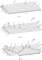
- Figure 1 discloses a plurality of adjacent optical fibers 2 having a diameter D and arranged in parallel forming a longitudinal optical fiber assembly 3 said assembly 3 having a width W and a length L. This assembly forms the basis for the optical fiber ribbon according to the present invention.
- the invention relates to an optical fiber ribbon 100-700, comprising
- the optical fiber units 5 each comprise a single fiber 2
- the optical fiber units 105 each comprise two optical fibers 2.
- optical fiber ribbon Several specific embodiments of said optical fiber ribbon are discussed below and disclosed in the drawings and each of these is discussed separately below.
- each of the optical fiber units comprises a group of at most three optical fibers, preferably two optical fibers, encapsulated with a matrix material.
- each optical fiber unit comprises a single optical fiber, allows the ribbons to have a more flat state and allows easier mass fusion splicing.
- the ribbon according to the present invention comprises six optical fiber units, each comprising two optical fibers, in total leading to a 12-optical fiber ribbon.
- a bond has a bonding length (l) and bonds are spaced apart in longitudinal direction by a distance (d).
- the bonding length is larger than the distance (l > d). The effect thereof is that the mechanical properties in terms of robustness are increased; a larger mechanical bond between the fibres is achieved.
- the bead as applied has an elongated form. It will flow into the groove between two adjacent optical fibers or - if the fiber unit comprises two or three fibers - two or three adjacent grouped optical fibers.
- the elongated beads forming a bond may have a width seen in plan view of between 75 and 350 micrometers, e.g. between 200 and 275 micrometers (viz. of similar dimension as the optical fiber).
- the bonding length (l) of a bead is between 1.5 and 20 mm.
- the bonding length of the bead is effectively defined by the ratio of bonding length of bonding distance (l/d) and by the ratio of pitch of the stepwise pattern over width of the optical fiber assembly (P/W).
- each of the plurality of optical fibers has substantially the same diameter.
- the optical fiber has a diameter of between 240 and 260 micrometers, more preferably 250 micrometers.
- the optical fibers may have a reduced diameter such as between 180 and 230 micrometers.
- the optical fiber assembly comprises between 6 and 36 optical fibers (including 6 and 36), such as between 12 and 24 optical fibers (including 12 and 24), for example 12 optical fibers.
- the fiber units may comprise fibers grouped in pairs as described above. When grouped the optical fiber assembly may comprise 6 to 18 groups of two fibers, such as 6 groups of two fibers, 12 groups of two fibers or 18 groups of two fibers.
- the fiber units may comprise three fibers, such as four fiber units of three fibers, or five fiber units of three fibers.
- the optical fibers are optical fibers comprising a first and second coating, and optionally an ink layer.
- a person skilled in the art is aware of the different types of primary coatings, secondary coatings and ink layers and the structure and thickness thereof.
- the beads have been arranged on only one side of said assembly.
- the beads have been arranged only on the upper surface of said assembly (seen in plan view when the optical fibers of the assembly are arranged in a ribbon like manner and not in a rolled up manner).
- the assembly could be seen as a ribbon-like assembly defining two side edges, an upper surface and a lower surface. Said upper and lower surfaces are not fully flat, since they are formed of a parallel arrangement of fiber unit structures.
- the upper and lower surfaces comprises parallel longitudinal grooves between adjacent optical fiber units.
- the beads are arranged to lie in the grooves formed between the optical fiber units.
- two successive beads of said plurality of beads have been connected by a transition part of said bonding material.
- said transition part is S-shaped.
- each two successive beads of said plurality of beads have been connected by a transition part of said bonding material.
- a succession of alternating beads and transition parts forms a thread, wherein at each longitudinal position of the optical fiber assembly there is at most one thread.
- the thread has a mass (in grams) per 10000 meter of between 60 and 120 dtex, preferably between 75 and 110 dtex.
- each two successive beads of said plurality of beads are free from each other in that no bonding material connecting said two beads is present. In other words, there is no thread of resin but merely individual beads.
- a number of successive beads form a stepwise pattern over the plurality of optical fiber units, the step each time being one optical fiber unit.
- each of the optical fiber units comprises a single fiber, that means only one fiber. In another embodiment, each of the optical fiber units comprises a group of two optical fibers encapsulated with a matrix material.
- said matrix material is an acrylate, such as an polyurethane acrylate or a polymethacrylate material.
- the encapsulating matrix material has a thickness of between 5 and 10 micrometers.
- the bead that follows the last bead of said pattern starts a subsequent stepwise pattern in the same width direction, preferably wherein the successive stepwise patterns are free from each other in that no bonding material connecting said two stepwise patterns is present.
- This succession of stepwise patterns may be repeated, preferably over the length of the fiber units, thereby forming a saw-tooth-like arrangement over the plurality of fiber units, seen in plan view.
- a pitch (P) is defined having a length equal to the recurrence of the stepwise pattern in the same width direction and wherein the pitch (P) has a length that is between 10 times W and 100 times W, preferably between 15 times W and 80 times W.
- Figure 4 discloses an embodiment of an optical fiber ribbon 400 having a saw-tooth like arrangement.
- This arrangement of Figure 4 none of the beads 4 are connected and the plurality of beads is arranged as a discontinuous line.
- the saw-tooth like arrangement has a constant repetition that follows the trace of a saw tooth wave with a pitch (P) (see Figure 4b ).
- Figure 5 discloses an embodiment of an optical fiber ribbon 500 having a saw-tooth like arrangement.
- the plurality of beads are arranged as a partly continuous line of said bonding material.
- the continuous line starts with a first bead 4 being applied between the first and second optical fibers 2 seen from the most distant edge.
- This continuous line continues over the top of said second optical fiber, with a transition part 9, to the groove between the second and third optical fiber, and further on over the top of said third optical fiber, with a transition part 9, to the groove between the third and fourth optical fiber and so on and so on.
- the continuous line ends in the groove between the fifth and sixth (last) optical fiber.
- a new continuous lines starts again in the groove between the first and second optical fiber at a distance P of the pitch (shown in fig. 4 ) from the first continuous line.
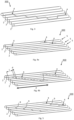
- Figure 6 discloses an embodiment of an optical fiber ribbon 600 having a saw-tooth like arrangement.
- the plurality of beads are arranged as a continuous line of said bonding material.
- the difference with the embodiment shown in Figure 5 is that there is also a resin line 9' between the bead 4 between the fifth and sixth optical fiber 2 of the first saw-tooth like arrangement and the bead 4 between the first and the second optical fiber 2 of the second saw-tooth like arrangement. This is a preferred embodiment.
- a pitch (P) is defined having a length equal to the recurrence of the stepwise pattern in the same width direction and wherein the pitch (P) has a length that is between 14 times W and 140 times W, preferably between 18 times W and 100 times W.
- the thermoplastic material has a melting point of between 55 and 170 °C, such as between 60 and 150 °C, for example between 120 and 150 °C.
- At a certain longitudinal position over the width (W) of the optical fiber assembly there is one bond. In an embodiment, at each longitudinal position over the width (W) of the optical fiber assembly there is one bond. In other words, at one certain longitudinal position there is only a bond between two optical fiber units, there is no bond present between another set of two adjacent optical fiber units. This structure minimizes the amount of bonds required and allows maximum flexibility.
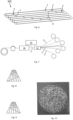
- Figure 10 shows a picture of a ribbon according to the present invention having a zig-zag like arrangement with a continuous line of a cured resin.
- the cross-section of figure 12 relates to a ribbon 700 according to the present invention, having fiber units 105 of each time a group of two optical fibers 2, encapsulated with a matrix material 8. Successive elongated rectilinear beads 4 of a bonding material have been arranged along a length of said assembly (one bead 4 is shown in the cross section). Each of said plurality of beads forms an elongated bond between two adjacent optical fiber units 105 as shown in figure 12 .
- optical fiber ribbon of the present invention may be used to form optical fiber cable units and optical fiber cables.
- An example of such an optical fiber cable unit is shown in Figure 11 , this unit has 24 ribbons of 12 optical fibers.
- This cable unit packs 288 optical fibers in a very high fiber density.
- the present invention relates to an optical fiber cable unit comprising one or more optical fiber ribbons according to the present invention surrounded by a polymeric sheath.
- the present invention also relates to an optical fiber cable comprising one or more of the optical fiber ribbons or optical fiber cable units according to the present invention.
- a bonding material is applied from a dispenser (or dispensing device) 14 to a surface, such as an upper surface of said assembly.
- Said second step may be in the form of applying a curable - preferably UV curable - resin.
- the application of said resin leads to said resin forming a stepwise pattern of a plurality of intermittently arranged beads 4 along the upper surface of said assembly 3.
- the second step may also be carried out by providing a thread of a thermoplastic material from the dispenser and heating said thermoplastic thread to above its softening point and applying said softened thermoplastic thread to said surface of said assembly 3 wherein the softened thermoplastic material is cooled down and forms a plurality of successive elongated rectilinear beads being configured to from bonds of said thermoplastic material.
- each of said beads being arranged to form a bond between two adjacent optical fibers units over a bonding length (l); and moreover, a bond connects two adjacent optical fibers units and a successive bond connects two adjacent optical fibers units at least one of which differs from the optical fibers units bonded by the preceding bond; and moreover, each of said bonds being distanced in longitudinal direction from a successive bond by a bonding distance (d).
- the bonding length is larger than the bonding distance (l > d) and the bonding length (l) is between 2 and 20 times the distance (d).
- said * applying a bonding material from a dispenser to a surface comprises (or consist of) the following steps: * applying a curable resin from the dispenser to the surface of said assembly wherein the resin forms the plurality of successive elongated rectilinear beads being configured to from bonds; and * passing said assembly with the beads applied thereon through a curing station for curing the resin of said beads to form said bonds of cured resin.
- said * applying a bonding material from a dispenser to a surface comprises (or consist of) the following step: * providing a thread of a thermoplastic material from the dispenser and heating said thermoplastic thread to above its softening point and applying said softened thermoplastic thread to said surface of said assembly wherein the softened thermoplastic material is cooled down and forms a plurality of successive elongated rectilinear beads being configured to from bonds of said thermoplastic material.
- the dispenser (dispensing device) is oscillating in a direction transverse to the longitudinal direction of the optical fiber assembly. Said oscillating device creates the stepwise pattern on one side of the optical fiber assembly; the tip of said dispenser may oscillate (vibrate) at a high frequency, such as in the order of between 100 and 200 Hz in a transverse direction. In an embodiment, the dispenser is oscillating in a direction transverse to the longitudinal direction (i.e. in the width direction) of the optical fiber assembly. The optical fiber assembly is moved in longitudinal directly, preferably by reels.
- the dispenser may deliver the liquid resin in fine droplets to the moving optical fiber assembly. Due to the surface tension of liquid resin it will flow together to form elongated beads.
- the curable resin has a viscosity at 23 °C of between 0.2 and 2 Pa.s (200 and 2000 cPS), preferably between 0.3 and 1 Pa.s ( 300 and 1000 cPS ) and more preferably between 0.4 and 0.6 Pa.s ( 400 and 600 cPS).
- the viscosity is measured at 23 °C using a Brookfield digital rotational viscometer Model DV-II with RV1 spindle at 10rpm.
- the bonding material is applied from a dispersing device as a thermoplastic thread and heated to above its softening point.
- the softening point of said thermoplastic thread is above 120°C.
- the softening point is determined according to the Vicat method with a load of 10N, according ASTM-D1525-09. After heating the thermoplastic thread is cooled down, e.g. by transporting the fiber assembly over cold sheaves.
Landscapes
- Physics & Mathematics (AREA)
- General Physics & Mathematics (AREA)
- Optics & Photonics (AREA)
- Engineering & Computer Science (AREA)
- Manufacturing & Machinery (AREA)
- Optical Fibers, Optical Fiber Cores, And Optical Fiber Bundles (AREA)
- Mechanical Coupling Of Light Guides (AREA)
- Manufacture, Treatment Of Glass Fibers (AREA)
Claims (15)
- Ruban de fibre optique (100-700), comprenant :* une pluralité d'unités de fibres optiques adjacentes (5, 105) s'étendant dans une direction longitudinale et disposées en parallèle formant un ensemble de fibres optiques (3) présentant une largeur, chacune des unités de fibres optiques (5, 105) comprenant soit- une fibre optique unique (2), ou- un groupe d'au plus trois fibres optiques (2), de préférence deux fibres optiques, encapsulées avec un matériau de matrice (8) ; et* une pluralité de billes (4) rectilignes allongées successives d'un matériau de liaison qui sont disposées le long d'une longueur dudit ensemble (3) ;- chacune de ladite pluralité de billes (4) étant configurée pour former une liaison allongée entre deux unités de fibres optiques adjacentes (5, 105) de la pluralité d'unités de fibres optiques ; dans lequel une première bille (4) formant une première liaison relie une première paire d'unités de fibres optiques adjacentes (5, 105) alors que la liaison successive formée par la bille successive relie une autre paire d'unités de fibres optiques adjacentes, dans lequel au moins une unité de fibre optique de l'autre paire diffère des unités de fibre optique de la première paire ;dans lequel, à chaque position longitudinale de l'ensemble de fibres optiques, il y a au plus une liaison ;caractérisé en ce qu'une liaison présente une longueur de liaison I ; lesdites liaisons étant espacées dans la direction longitudinale d'une distance d ; la longueur de liaison est supérieure à la distance, l>d, et la longueur de liaison est comprise entre 2 et 20 fois la distance.
- Ruban (100-700) selon la revendication 1, dans lequel la longueur de liaison est comprise entre 4 et 15 fois la distance.
- Ruban (100-700) selon la revendication 1 ou 2, dans lequel lesdites billes (4) ont été disposées sur un seul côté dudit ensemble (3).
- Ruban (100-700) selon l'une quelconque des revendications précédentes, dans lequel deux, de préférence chaque deux billes (4) successives de ladite pluralité de billes ont été reliées par une partie de transition dudit matériau de liaison, de préférence dans lequel, dans une vue en plan, ladite partie de transition est en forme de S, de préférence dans lequel une succession de billes et de parties de transition alternées forme un filament, dans lequel, à chaque position longitudinale de l'ensemble de fibres optiques (3), il y a au plus un filament.
- Ruban (100-700) selon l'une quelconque des revendications 1-3, dans lequel chaque deux billes (4) successives de ladite pluralité de billes (4) sont libres l'une par rapport à l'autre en ce qu'il n'y a aucun matériau de liaison reliant lesdites deux billes (4).
- Ruban (100-700) selon l'une quelconque des revendications précédentes, dans lequel un certain nombre de billes (4) successives forment un motif en escaliers sur la pluralité d'unités de fibre optique (5, 105), le pas étant à chaque fois une unité de fibre optique.
- Ruban (100-700) selon la revendication 6, dans lequel, à une extrémité dudit motif en escaliers de billes, la bille (4) qui suit la dernière bille dudit motif initie un motif en escaliers suivant dans la même direction de largeur, de préférence dans lequel les motifs en escaliers successifs sont libres l'un de l'autre en ce qu'il n'y a aucun matériau de liaison reliant lesdits deux motifs en escaliers, de préférence dans lequel un pas P est défini présentant une longueur égale à la récurrence du motif en escaliers dans la même direction de largeur et dans lequel le pas présente une longueur qui est comprise entre 10 fois W et 100 fois W, de préférence entre 15 fois W et 80 fois W.
- Ruban (100-700) selon la revendication 6, dans lequel un premier motif en escaliers a été formé dans une première direction de largeur et dans lequel, à l'extrémité dudit motif en escaliers, un autre motif en escaliers dans la direction opposée a été formé, de préférence dans lequel un pas est défini présentant une longueur égale à la récurrence du motif en escaliers dans la même direction de largeur et dans lequel le pas présente une longueur qui est comprise entre 14 fois W et 140 fois W, de préférence entre 18 fois W et 100 fois W.
- Ruban (100-700) selon l'une quelconque des revendications précédentes, dans lequel le matériau de liaison présente un allongement à la rupture d'au moins 150 %, de préférence d'au moins 175 %, de manière plus préférée d'au moins 200 %, de préférence encore au moins 220 % et un module d'élasticité compris entre 10 et 16 MPa.
- Ruban selon l'une quelconque des revendications précédentes, dans lequel le matériau de liaison est une résine durcie ou un matériau thermoplastique et/ou dans lequel la longueur de liaison I est comprise entre 1,5 et 20 mm.
- Procédé de production d'un ruban de fibre optique (100-700), ledit procédé comprenant* l'alimentation d'une pluralité d'unités de fibres optiques (5, 105) pour fournir un ensemble de fibres optiques longitudinales (3) présentant une largeur ; dans lequel la pluralité d'unités de fibres optiques (5, 105) sont en parallèle et adjacentes les unes aux autres, chacune des unités de fibres optiques (5, 105) comprenant soit- une fibre optique unique (2), ou- un groupe d'au plus trois fibres optiques (2), de préférence deux fibres optiques, encapsulées avec un matériau de matrice (8) ;* l'application d'un matériau de liaison d'un distributeur à une surface dudit ensemble (3), dans lequel le matériau de liaison forme une pluralité de billes (4) rectilignes allongées successives configurées pour former des liaisons ; dans lequel- chacune de ladite pluralité de billes (4) forme une liaison allongée entre deux unités de fibres optiques adjacentes (5, 105) de la pluralité d'unités de fibres optiques ; dans lequel ladite liaison relie une première paire d'unités de fibres optiques adjacentes (5, 105) alors que la liaison successive de celles-ci, formée par l'une successive de ladite pluralité de billes (4), relie une autre paire d'unités de fibres optiques adjacentes, au moins une unité de fibres optiques de l'autre paire diffère des unités de fibres optiques de la première paire, et- dans lequel le matériau de liaison est appliqué de telle manière qu'il y a au plus une liaison à chaque position longitudinale de l'ensemble de fibres optiques (3) ;- caractérisé en ce qu'une liaison présente une longueur de liaison I ; lesdites liaisons étant espacées dans la direction longitudinale d'une distance d ; la longueur de liaison est supérieure à la distance, l>d, et la longueur de liaison est comprise entre 2 et 20 fois la distance.
- Procédé selon la revendication 11, dans lequel ladite* application d'un matériau de liaison d'un distributeur à une surface ; comprend les étapes suivantes :* l'application d'une résine durcissable du distributeur à la surface dudit ensemble (3), dans lequel la résine forme la pluralité de billes (4) rectilignes allongées successives qui sont configurées pour former des liaisons ; et* le passage dudit ensemble avec les billes appliquées sur celui-ci à travers un poste de durcissement pour durcir la résine desdites billes pour former lesdites liaisons de résine durcie.
- Procédé selon la revendication 11, dans lequel ladite* application d'un matériau de liaison d'un distributeur à une surface ; comprend l'étape suivante :* la fourniture d'un filament d'un matériau thermoplastique à partir du distributeur et le chauffage dudit filament thermoplastique au-dessus de son point de ramollissement et l'application dudit filament thermoplastique ramolli à ladite surface dudit ensemble (3), dans lequel le matériau thermoplastique ramolli est refroidi et forme une pluralité de billes (4) rectilignes allongées successives qui sont configurées pour former des liaisons dudit matériau thermoplastique, de préférence dans lequel la résine durcissable présente une viscosité à 23°C comprise entre 0,2 et 2 Pa.s (200 et 2000 cPS), de manière plus préférée entre 0,3 et 1 Pa.s (300 et 1000 cPS) et de préférence encore entre 0,4 et 0,6 Pa.s (400 et 600 cPS).
- Procédé selon l'une quelconque des revendications 11 à 13, dans lequel le distributeur oscille dans une direction transverse à la direction longitudinale de l'ensemble de fibres optiques (3).
- Procédé selon la revendication 13, dans lequel le poste de durcissement émet un rayonnement ultraviolet UV ou à faisceau d'électrons pour durcir lesdites billes (4) de résine durcissable.
Priority Applications (1)
| Application Number | Priority Date | Filing Date | Title |
|---|---|---|---|
| PL17737594.6T PL3652575T3 (pl) | 2017-07-11 | 2017-07-11 | Taśma światłowodowa oraz sposób jej wytwarzania |
Applications Claiming Priority (1)
| Application Number | Priority Date | Filing Date | Title |
|---|---|---|---|
| PCT/EP2017/067454 WO2019011417A1 (fr) | 2017-07-11 | 2017-07-11 | Ruban de fibres optiques et son procédé de production |
Publications (3)
| Publication Number | Publication Date |
|---|---|
| EP3652575A1 EP3652575A1 (fr) | 2020-05-20 |
| EP3652575C0 EP3652575C0 (fr) | 2023-12-27 |
| EP3652575B1 true EP3652575B1 (fr) | 2023-12-27 |
Family
ID=59313267
Family Applications (1)
| Application Number | Title | Priority Date | Filing Date |
|---|---|---|---|
| EP17737594.6A Active EP3652575B1 (fr) | 2017-07-11 | 2017-07-11 | Ruban de fibres optiques et son procédé de production |
Country Status (16)
| Country | Link |
|---|---|
| US (1) | US10983297B2 (fr) |
| EP (1) | EP3652575B1 (fr) |
| KR (1) | KR102534677B1 (fr) |
| CN (1) | CN110998402A (fr) |
| AR (1) | AR112653A1 (fr) |
| AU (1) | AU2017423261B2 (fr) |
| BR (1) | BR112020000333B1 (fr) |
| CA (1) | CA3067738C (fr) |
| CL (1) | CL2020000048A1 (fr) |
| CO (1) | CO2019014119A2 (fr) |
| ES (1) | ES2968206T3 (fr) |
| MX (1) | MX2020000069A (fr) |
| NZ (1) | NZ760306A (fr) |
| PL (1) | PL3652575T3 (fr) |
| RU (1) | RU2738329C1 (fr) |
| WO (1) | WO2019011417A1 (fr) |
Cited By (1)
| Publication number | Priority date | Publication date | Assignee | Title |
|---|---|---|---|---|
| EP3614188B1 (fr) * | 2018-08-24 | 2025-09-03 | Prysmian S.p.A. | Rubans flexibles de fibres optiques et leurs procédés de formation |
Families Citing this family (33)
| Publication number | Priority date | Publication date | Assignee | Title |
|---|---|---|---|---|
| AU2017423261B2 (en) | 2017-07-11 | 2023-07-20 | Prysmian S.P.A. | An optical fiber ribbon and a method of producing the same |
| PL3652576T3 (pl) | 2017-07-11 | 2022-11-07 | Prysmian S.P.A. | Zespół taśmy światłowodowej i sposób jej wytwarzania |
| US11256051B2 (en) | 2018-01-15 | 2022-02-22 | Prysmian S.P.A. | Flexible optical-fiber ribbon |
| US11500171B2 (en) | 2018-01-15 | 2022-11-15 | Prysmian S.P.A. | Optical fiber ribbon and a method and system of producing the same |
| AU2018401778C1 (en) | 2018-01-15 | 2024-08-08 | Prysmian S.P.A. | A method for producing a flexible optical fiber ribbon and said ribbon. |
| JP7050716B2 (ja) * | 2019-04-24 | 2022-04-08 | 古河電気工業株式会社 | 光ファイバテープ心線、光ファイバケーブル |
| US11131817B2 (en) * | 2019-05-09 | 2021-09-28 | Go!Foton Holdings, Inc. | Multi-fiber cable |
| US11300742B2 (en) * | 2019-08-14 | 2022-04-12 | Sterlite Technologies Limited | Optical fiber ribbon cable |
| JP7157026B2 (ja) * | 2019-09-12 | 2022-10-19 | 株式会社フジクラ | 光ファイバ整列方法、光ファイバ融着方法、コネクタ付き光ファイバテープの製造方法及び間欠連結型の光ファイバテープ |
| US10884213B1 (en) | 2019-11-14 | 2021-01-05 | Prysmian S.P.A. | Optical-fiber ribbon with distorted sinusoidal adhesive pattern and method therefor |
| WO2021133534A1 (fr) | 2019-12-23 | 2021-07-01 | Corning Research & Development Corporation | Ruban à liaison intermittente ayant des régions de liaison avec de multiples matériaux |
| EP4139730A4 (fr) | 2020-04-24 | 2024-06-19 | CommScope Technologies LLC | Systèmes et procédés de routage de fibres |
| KR102854109B1 (ko) * | 2020-07-21 | 2025-09-02 | 엘에스전선 주식회사 | 광섬유 리본 |
| EP4196831A4 (fr) | 2020-08-17 | 2024-07-24 | Corning Research & Development Corporation | Ruban de fibres optiques à liaison intermittente |
| CN116324556A (zh) | 2020-08-31 | 2023-06-23 | 康宁研究与开发公司 | 具有用湿碰湿工艺产生的间歇结合部的间歇性结合的带 |
| WO2022054940A1 (fr) * | 2020-09-14 | 2022-03-17 | 住友電気工業株式会社 | Ruban de fibres optiques et procédé de fabrication de ruban de fibres optiques |
| WO2022086700A1 (fr) * | 2020-10-19 | 2022-04-28 | Corning Research & Development Corporation | Ruban à liaisons intermittentes non chevauchantes entre des sous-unités de fibres optiques |
| EP4016155A1 (fr) * | 2020-12-21 | 2022-06-22 | Taihan Fiberoptics Co., Ltd. | Ruban enroulable à fibre optique et son procédé de fabrication |
| US11460652B2 (en) | 2020-12-22 | 2022-10-04 | Prysmian S.P.A. | Optical-fiber ribbon with adhesive-free gaps |
| US11860429B2 (en) | 2020-12-22 | 2024-01-02 | Prysmian S.P.A. | Optical-fiber ribbon with spaced optical-fiber units |
| US11442238B2 (en) | 2020-12-22 | 2022-09-13 | Prysmian S.P.A. | Optical-fiber ribbon with spaced optical-fiber units |
| US20240184069A1 (en) * | 2021-04-13 | 2024-06-06 | Ofs Fitel Llc | Optical fiber rollable ribbon having low young's modulus bonding matrix material |
| FR3121761A1 (fr) * | 2021-04-13 | 2022-10-14 | Acome | Faisceau de communication optique et câble optique associé |
| WO2023043625A1 (fr) * | 2021-09-17 | 2023-03-23 | Corning Research & Development Corporation | Ruban de fibres optiques à liaison intermittente avec des fibres à diamètre réduit |
| JP7692491B2 (ja) * | 2021-10-04 | 2025-06-13 | 株式会社フジクラ | 光ファイバテープ心線 |
| CN114280748B (zh) * | 2022-03-04 | 2022-05-17 | 烽火通信科技股份有限公司 | 一种柔性光纤带、带缆及制备方法 |
| WO2023192029A1 (fr) * | 2022-03-30 | 2023-10-05 | Corning Research & Development Corporation | Bande de fibres optiques à trame tissée |
| WO2023219105A1 (fr) * | 2022-05-11 | 2023-11-16 | 住友電気工業株式会社 | Ruban de fibres optiques |
| AT525543B1 (de) * | 2022-05-16 | 2023-05-15 | Medek & Schoerner Gmbh | Lichtleiterfaserband und Verfahren zu dessen Herstellung |
| JPWO2024014488A1 (fr) | 2022-07-13 | 2024-01-18 | ||
| US20250155662A1 (en) | 2023-11-09 | 2025-05-15 | Prysmian S.P.A. | Optical-Fiber Ribbon |
| WO2026028399A1 (fr) * | 2024-08-01 | 2026-02-05 | 住友電気工業株式会社 | Coeur de ruban de fibres optiques et câble optique |
| WO2026048905A1 (fr) * | 2024-08-28 | 2026-03-05 | 住友電気工業株式会社 | Ruban de fibres optiques et procédé de fabrication de ruban de fibres optiques |
Citations (2)
| Publication number | Priority date | Publication date | Assignee | Title |
|---|---|---|---|---|
| WO2012023508A1 (fr) * | 2010-08-19 | 2012-02-23 | 株式会社フジクラ | Procédé de fabrication de bande de fibres optiques, dispositif de fabrication de bandes de fibres optiques mettant en œuvre ledit procédé de fabrication, et bande de fibres optiques fabriquée en utilisant ledit procédé |
| WO2013058206A1 (fr) * | 2011-10-18 | 2013-04-25 | 株式会社フジクラ | Fil cœur de fibre optique en ruban et câble à fibres optiques abritant ledit fil cœur de fibre optique en ruban |
Family Cites Families (37)
| Publication number | Priority date | Publication date | Assignee | Title |
|---|---|---|---|---|
| FR2693560A1 (fr) | 1992-07-10 | 1994-01-14 | Alcatel Cable | Câble cylindrique à fibres optiques. |
| FR2727212B1 (fr) | 1994-11-21 | 1997-01-03 | Alcatel Cable | Procede de fabrication d'un module cylindrique de fibres optiques |
| FR2727213B1 (fr) | 1994-11-21 | 1996-12-27 | Alcatel Cable | Cable a fibres optiques et procede de fabrication d'un module de fibres optiques appartenant a un tel cable |
| US6381390B1 (en) | 1999-04-06 | 2002-04-30 | Alcatel | Color-coded optical fiber ribbon and die for making the same |
| US6584257B1 (en) | 2000-12-27 | 2003-06-24 | Corning Cable Systems, Llc | Fiber optic assembly and method of making same |
| JP2003232972A (ja) | 2002-02-07 | 2003-08-22 | Sumitomo Electric Ind Ltd | 光ファイバテープ心線 |
| FR2893149B1 (fr) | 2005-11-10 | 2008-01-11 | Draka Comteq France | Fibre optique monomode. |
| DK2206001T3 (da) | 2007-11-09 | 2014-07-07 | Draka Comteq Bv | Optisk fiber, der er modstandsdygtig over for mikrobøjning |
| US8600206B2 (en) | 2008-11-07 | 2013-12-03 | Draka Comteq, B.V. | Reduced-diameter optical fiber |
| SE535250C2 (sv) | 2007-12-11 | 2012-06-05 | Prysmian Comm Cables And Systems Usa Llc | Metod för tillverkning av ett optiskt fiberband samt delningsbart optiskt fiberband |
| FR2930997B1 (fr) | 2008-05-06 | 2010-08-13 | Draka Comteq France Sa | Fibre optique monomode |
| CN102057309B (zh) * | 2008-06-30 | 2014-04-16 | 日本电信电话株式会社 | 光纤缆线以及光纤带 |
| JP5000605B2 (ja) | 2008-08-18 | 2012-08-15 | 日本電信電話株式会社 | 光ファイバテープの単心分離方法 |
| US7822307B1 (en) | 2009-04-07 | 2010-10-26 | Sumitomo Electric Industries, Ltd. | Optical fiber ribbon for wiring of equipment and connector-attached optical fiber ribbon for wiring of equipment |
| JP5291042B2 (ja) * | 2010-04-08 | 2013-09-18 | 古河電気工業株式会社 | 光ファイバテープ心線の製造方法及び光ファイバテープ心線の製造装置 |
| JP2012027130A (ja) | 2010-07-21 | 2012-02-09 | Sumitomo Electric Ind Ltd | 光ファイバテープ心線および光ケーブル |
| JP5162645B2 (ja) | 2010-11-08 | 2013-03-13 | 株式会社フジクラ | 光ファイバテープ心線の製造方法、製造装置、光ファイバテープ心線及び光ファイバケーブル |
| JP5309189B2 (ja) | 2011-06-03 | 2013-10-09 | 株式会社フジクラ | 光ファイバテープ心線の製造方法及びその製造方法で製造した光ファイバテープ心線 |
| JP5944762B2 (ja) | 2012-07-03 | 2016-07-05 | 昭和電線ケーブルシステム株式会社 | 間欠型光ファイバテープ心線の製造方法および製造装置 |
| CN103858041A (zh) * | 2012-10-03 | 2014-06-11 | 住友电气工业株式会社 | 光纤带状芯线 |
| JP5789630B2 (ja) * | 2013-04-01 | 2015-10-07 | 株式会社フジクラ | 光ユニット及び光ファイバケーブル |
| JP5852045B2 (ja) | 2013-05-07 | 2016-02-03 | 株式会社フジクラ | 光ファイバテープ心線及び光ファイバケーブル |
| JP5695138B2 (ja) | 2013-07-16 | 2015-04-01 | 昭和電線ケーブルシステム株式会社 | 間欠型光ファイバテープ心線の検査方法、製造方法および検査装置 |
| JP2015108756A (ja) | 2013-12-05 | 2015-06-11 | 住友電気工業株式会社 | 光ファイバユニット、光ファイバケーブルおよび光ファイバユニットの製造方法 |
| JP2016075746A (ja) * | 2014-10-03 | 2016-05-12 | 住友電気工業株式会社 | 間欠型光ファイバテープ心線及びその製造方法 |
| JP6412779B2 (ja) * | 2014-11-20 | 2018-10-24 | 株式会社フジクラ | 光ファイバテープ心線、光ファイバケーブル、および、光ファイバテープ心線の製造方法 |
| JP6408389B2 (ja) * | 2015-01-26 | 2018-10-17 | 株式会社フジクラ | 光ファイバテープの製造方法、異常検出方法及び製造システム |
| US11845885B2 (en) | 2015-12-30 | 2023-12-19 | 3M Innovative Properties Company | Dual stage structural bonding adhesive |
| JP2017134360A (ja) | 2016-01-29 | 2017-08-03 | 住友電気工業株式会社 | 光ファイバテープ心線および光ケーブル |
| US9880368B2 (en) | 2016-02-02 | 2018-01-30 | Ofs Fitel, Llc | Method for high speed processing of partially bonded ribbon structures |
| EP3491441B1 (fr) | 2016-07-27 | 2020-05-27 | Prysmian S.p.A. | Ruban de fibres optiques flexible |
| US10167396B2 (en) | 2017-05-03 | 2019-01-01 | Corning Incorporated | Low smoke fire-resistant optical ribbon |
| JP6383457B2 (ja) | 2017-05-09 | 2018-08-29 | 株式会社フジクラ | 間欠連結型光ファイバテープの検査方法、検査装置及び製造方法 |
| PL3652576T3 (pl) | 2017-07-11 | 2022-11-07 | Prysmian S.P.A. | Zespół taśmy światłowodowej i sposób jej wytwarzania |
| AU2017423261B2 (en) | 2017-07-11 | 2023-07-20 | Prysmian S.P.A. | An optical fiber ribbon and a method of producing the same |
| AU2018401778C1 (en) | 2018-01-15 | 2024-08-08 | Prysmian S.P.A. | A method for producing a flexible optical fiber ribbon and said ribbon. |
| US11500171B2 (en) | 2018-01-15 | 2022-11-15 | Prysmian S.P.A. | Optical fiber ribbon and a method and system of producing the same |
-
2017
- 2017-07-11 AU AU2017423261A patent/AU2017423261B2/en active Active
- 2017-07-11 EP EP17737594.6A patent/EP3652575B1/fr active Active
- 2017-07-11 US US16/629,732 patent/US10983297B2/en active Active
- 2017-07-11 ES ES17737594T patent/ES2968206T3/es active Active
- 2017-07-11 CA CA3067738A patent/CA3067738C/fr active Active
- 2017-07-11 KR KR1020207003670A patent/KR102534677B1/ko active Active
- 2017-07-11 WO PCT/EP2017/067454 patent/WO2019011417A1/fr not_active Ceased
- 2017-07-11 BR BR112020000333-6A patent/BR112020000333B1/pt active IP Right Grant
- 2017-07-11 NZ NZ760306A patent/NZ760306A/en unknown
- 2017-07-11 MX MX2020000069A patent/MX2020000069A/es unknown
- 2017-07-11 RU RU2020106114A patent/RU2738329C1/ru active
- 2017-07-11 CN CN201780093046.4A patent/CN110998402A/zh active Pending
- 2017-07-11 PL PL17737594.6T patent/PL3652575T3/pl unknown
-
2018
- 2018-07-10 AR ARP180101911 patent/AR112653A1/es active IP Right Grant
-
2019
- 2019-12-16 CO CONC2019/0014119A patent/CO2019014119A2/es unknown
-
2020
- 2020-01-08 CL CL2020000048A patent/CL2020000048A1/es unknown
Patent Citations (2)
| Publication number | Priority date | Publication date | Assignee | Title |
|---|---|---|---|---|
| WO2012023508A1 (fr) * | 2010-08-19 | 2012-02-23 | 株式会社フジクラ | Procédé de fabrication de bande de fibres optiques, dispositif de fabrication de bandes de fibres optiques mettant en œuvre ledit procédé de fabrication, et bande de fibres optiques fabriquée en utilisant ledit procédé |
| WO2013058206A1 (fr) * | 2011-10-18 | 2013-04-25 | 株式会社フジクラ | Fil cœur de fibre optique en ruban et câble à fibres optiques abritant ledit fil cœur de fibre optique en ruban |
Cited By (1)
| Publication number | Priority date | Publication date | Assignee | Title |
|---|---|---|---|---|
| EP3614188B1 (fr) * | 2018-08-24 | 2025-09-03 | Prysmian S.p.A. | Rubans flexibles de fibres optiques et leurs procédés de formation |
Also Published As
| Publication number | Publication date |
|---|---|
| US20200271879A1 (en) | 2020-08-27 |
| NZ760306A (en) | 2022-07-29 |
| BR112020000333A2 (pt) | 2020-07-14 |
| RU2738329C1 (ru) | 2020-12-11 |
| MX2020000069A (es) | 2020-08-20 |
| EP3652575C0 (fr) | 2023-12-27 |
| CA3067738A1 (fr) | 2019-01-17 |
| EP3652575A1 (fr) | 2020-05-20 |
| AU2017423261A1 (en) | 2020-01-16 |
| KR20200023474A (ko) | 2020-03-04 |
| US10983297B2 (en) | 2021-04-20 |
| CN110998402A (zh) | 2020-04-10 |
| KR102534677B1 (ko) | 2023-05-22 |
| PL3652575T3 (pl) | 2024-03-18 |
| WO2019011417A1 (fr) | 2019-01-17 |
| AR112653A1 (es) | 2019-11-27 |
| CA3067738C (fr) | 2024-05-28 |
| BR112020000333B1 (pt) | 2022-06-07 |
| CL2020000048A1 (es) | 2020-08-28 |
| ES2968206T3 (es) | 2024-05-08 |
| AU2017423261B2 (en) | 2023-07-20 |
| CO2019014119A2 (es) | 2020-04-01 |
Similar Documents
| Publication | Publication Date | Title |
|---|---|---|
| CA3067738C (fr) | Ruban de fibres optiques et son procede de production | |
| AU2018401778B2 (en) | A method for producing a flexible optical fiber ribbon and said ribbon. | |
| EP3652576B1 (fr) | Assemblage de rubans de fibres optiques et son procédé de production | |
| AU2018401777B2 (en) | An optical fiber ribbon and a method and system of producing the same | |
| US20260086309A1 (en) | Ribbon with non-overlapping intermittent bonds between optical fiber subunits | |
| CA3088032C (fr) | Procede de production d'un ruban souple de fibre optique et ledit ruban | |
| NZ766575B2 (en) | A method for producing a flexible optical fiber ribbon and said ribbon. | |
| BR112020014340B1 (pt) | Método de produção de uma fita de fibra óptica e fita de fibra óptica |
Legal Events
| Date | Code | Title | Description |
|---|---|---|---|
| STAA | Information on the status of an ep patent application or granted ep patent |
Free format text: STATUS: UNKNOWN |
|
| STAA | Information on the status of an ep patent application or granted ep patent |
Free format text: STATUS: THE INTERNATIONAL PUBLICATION HAS BEEN MADE |
|
| PUAI | Public reference made under article 153(3) epc to a published international application that has entered the european phase |
Free format text: ORIGINAL CODE: 0009012 |
|
| STAA | Information on the status of an ep patent application or granted ep patent |
Free format text: STATUS: REQUEST FOR EXAMINATION WAS MADE |
|
| 17P | Request for examination filed |
Effective date: 20191231 |
|
| AK | Designated contracting states |
Kind code of ref document: A1 Designated state(s): AL AT BE BG CH CY CZ DE DK EE ES FI FR GB GR HR HU IE IS IT LI LT LU LV MC MK MT NL NO PL PT RO RS SE SI SK SM TR |
|
| AX | Request for extension of the european patent |
Extension state: BA ME |
|
| DAV | Request for validation of the european patent (deleted) | ||
| DAX | Request for extension of the european patent (deleted) | ||
| STAA | Information on the status of an ep patent application or granted ep patent |
Free format text: STATUS: EXAMINATION IS IN PROGRESS |
|
| 17Q | First examination report despatched |
Effective date: 20220105 |
|
| GRAP | Despatch of communication of intention to grant a patent |
Free format text: ORIGINAL CODE: EPIDOSNIGR1 |
|
| STAA | Information on the status of an ep patent application or granted ep patent |
Free format text: STATUS: GRANT OF PATENT IS INTENDED |
|
| INTG | Intention to grant announced |
Effective date: 20230906 |
|
| GRAS | Grant fee paid |
Free format text: ORIGINAL CODE: EPIDOSNIGR3 |
|
| GRAA | (expected) grant |
Free format text: ORIGINAL CODE: 0009210 |
|
| STAA | Information on the status of an ep patent application or granted ep patent |
Free format text: STATUS: THE PATENT HAS BEEN GRANTED |
|
| AK | Designated contracting states |
Kind code of ref document: B1 Designated state(s): AL AT BE BG CH CY CZ DE DK EE ES FI FR GB GR HR HU IE IS IT LI LT LU LV MC MK MT NL NO PL PT RO RS SE SI SK SM TR |
|
| REG | Reference to a national code |
Ref country code: GB Ref legal event code: FG4D |
|
| REG | Reference to a national code |
Ref country code: CH Ref legal event code: EP |
|
| REG | Reference to a national code |
Ref country code: DE Ref legal event code: R096 Ref document number: 602017077903 Country of ref document: DE |
|
| REG | Reference to a national code |
Ref country code: IE Ref legal event code: FG4D |
|
| REG | Reference to a national code |
Ref country code: GR Ref legal event code: EP Ref document number: 20240400148 Country of ref document: GR Effective date: 20240209 |
|
| U01 | Request for unitary effect filed |
Effective date: 20240105 |
|
| U07 | Unitary effect registered |
Designated state(s): AT BE BG DE DK EE FI FR IT LT LU LV MT NL PT SE SI Effective date: 20240116 |
|
| REG | Reference to a national code |
Ref country code: ES Ref legal event code: FG2A Ref document number: 2968206 Country of ref document: ES Kind code of ref document: T3 Effective date: 20240508 |
|
| PG25 | Lapsed in a contracting state [announced via postgrant information from national office to epo] |
Ref country code: RS Free format text: LAPSE BECAUSE OF FAILURE TO SUBMIT A TRANSLATION OF THE DESCRIPTION OR TO PAY THE FEE WITHIN THE PRESCRIBED TIME-LIMIT Effective date: 20231227 Ref country code: NO Free format text: LAPSE BECAUSE OF FAILURE TO SUBMIT A TRANSLATION OF THE DESCRIPTION OR TO PAY THE FEE WITHIN THE PRESCRIBED TIME-LIMIT Effective date: 20240327 Ref country code: HR Free format text: LAPSE BECAUSE OF FAILURE TO SUBMIT A TRANSLATION OF THE DESCRIPTION OR TO PAY THE FEE WITHIN THE PRESCRIBED TIME-LIMIT Effective date: 20231227 |
|
| PG25 | Lapsed in a contracting state [announced via postgrant information from national office to epo] |
Ref country code: IS Free format text: LAPSE BECAUSE OF FAILURE TO SUBMIT A TRANSLATION OF THE DESCRIPTION OR TO PAY THE FEE WITHIN THE PRESCRIBED TIME-LIMIT Effective date: 20240427 |
|
| PG25 | Lapsed in a contracting state [announced via postgrant information from national office to epo] |
Ref country code: CZ Free format text: LAPSE BECAUSE OF FAILURE TO SUBMIT A TRANSLATION OF THE DESCRIPTION OR TO PAY THE FEE WITHIN THE PRESCRIBED TIME-LIMIT Effective date: 20231227 |
|
| PG25 | Lapsed in a contracting state [announced via postgrant information from national office to epo] |
Ref country code: SK Free format text: LAPSE BECAUSE OF FAILURE TO SUBMIT A TRANSLATION OF THE DESCRIPTION OR TO PAY THE FEE WITHIN THE PRESCRIBED TIME-LIMIT Effective date: 20231227 |
|
| PG25 | Lapsed in a contracting state [announced via postgrant information from national office to epo] |
Ref country code: SM Free format text: LAPSE BECAUSE OF FAILURE TO SUBMIT A TRANSLATION OF THE DESCRIPTION OR TO PAY THE FEE WITHIN THE PRESCRIBED TIME-LIMIT Effective date: 20231227 Ref country code: SK Free format text: LAPSE BECAUSE OF FAILURE TO SUBMIT A TRANSLATION OF THE DESCRIPTION OR TO PAY THE FEE WITHIN THE PRESCRIBED TIME-LIMIT Effective date: 20231227 Ref country code: IS Free format text: LAPSE BECAUSE OF FAILURE TO SUBMIT A TRANSLATION OF THE DESCRIPTION OR TO PAY THE FEE WITHIN THE PRESCRIBED TIME-LIMIT Effective date: 20240427 Ref country code: CZ Free format text: LAPSE BECAUSE OF FAILURE TO SUBMIT A TRANSLATION OF THE DESCRIPTION OR TO PAY THE FEE WITHIN THE PRESCRIBED TIME-LIMIT Effective date: 20231227 |
|
| U20 | Renewal fee for the european patent with unitary effect paid |
Year of fee payment: 8 Effective date: 20240729 |
|
| REG | Reference to a national code |
Ref country code: DE Ref legal event code: R097 Ref document number: 602017077903 Country of ref document: DE |
|
| PLBE | No opposition filed within time limit |
Free format text: ORIGINAL CODE: 0009261 |
|
| STAA | Information on the status of an ep patent application or granted ep patent |
Free format text: STATUS: NO OPPOSITION FILED WITHIN TIME LIMIT |
|
| 26N | No opposition filed |
Effective date: 20240930 |
|
| PG25 | Lapsed in a contracting state [announced via postgrant information from national office to epo] |
Ref country code: MC Free format text: LAPSE BECAUSE OF FAILURE TO SUBMIT A TRANSLATION OF THE DESCRIPTION OR TO PAY THE FEE WITHIN THE PRESCRIBED TIME-LIMIT Effective date: 20231227 |
|
| REG | Reference to a national code |
Ref country code: CH Ref legal event code: PL |
|
| PG25 | Lapsed in a contracting state [announced via postgrant information from national office to epo] |
Ref country code: CH Free format text: LAPSE BECAUSE OF NON-PAYMENT OF DUE FEES Effective date: 20240731 |
|
| PGFP | Annual fee paid to national office [announced via postgrant information from national office to epo] |
Ref country code: PL Payment date: 20250618 Year of fee payment: 9 |
|
| PG25 | Lapsed in a contracting state [announced via postgrant information from national office to epo] |
Ref country code: IE Free format text: LAPSE BECAUSE OF NON-PAYMENT OF DUE FEES Effective date: 20240711 |
|
| U20 | Renewal fee for the european patent with unitary effect paid |
Year of fee payment: 9 Effective date: 20250728 |
|
| PGFP | Annual fee paid to national office [announced via postgrant information from national office to epo] |
Ref country code: ES Payment date: 20250801 Year of fee payment: 9 |
|
| PGFP | Annual fee paid to national office [announced via postgrant information from national office to epo] |
Ref country code: GR Payment date: 20250729 Year of fee payment: 9 |
|
| PGFP | Annual fee paid to national office [announced via postgrant information from national office to epo] |
Ref country code: TR Payment date: 20250709 Year of fee payment: 9 |
|
| PGFP | Annual fee paid to national office [announced via postgrant information from national office to epo] |
Ref country code: GB Payment date: 20250728 Year of fee payment: 9 |
|
| PGFP | Annual fee paid to national office [announced via postgrant information from national office to epo] |
Ref country code: RO Payment date: 20250701 Year of fee payment: 9 |
|
| PG25 | Lapsed in a contracting state [announced via postgrant information from national office to epo] |
Ref country code: CY Free format text: LAPSE BECAUSE OF FAILURE TO SUBMIT A TRANSLATION OF THE DESCRIPTION OR TO PAY THE FEE WITHIN THE PRESCRIBED TIME-LIMIT; INVALID AB INITIO Effective date: 20170711 |
|
| PG25 | Lapsed in a contracting state [announced via postgrant information from national office to epo] |
Ref country code: HU Free format text: LAPSE BECAUSE OF FAILURE TO SUBMIT A TRANSLATION OF THE DESCRIPTION OR TO PAY THE FEE WITHIN THE PRESCRIBED TIME-LIMIT; INVALID AB INITIO Effective date: 20170711 |