EP3653174A2 - Gelenkersatzvorrichtung und -methode für das metatarsophalangealgelenk - Google Patents
Gelenkersatzvorrichtung und -methode für das metatarsophalangealgelenk Download PDFInfo
- Publication number
- EP3653174A2 EP3653174A2 EP19194431.3A EP19194431A EP3653174A2 EP 3653174 A2 EP3653174 A2 EP 3653174A2 EP 19194431 A EP19194431 A EP 19194431A EP 3653174 A2 EP3653174 A2 EP 3653174A2
- Authority
- EP
- European Patent Office
- Prior art keywords
- anchor
- fibers
- flexible spacer
- component
- bone
- Prior art date
- Legal status (The legal status is an assumption and is not a legal conclusion. Google has not performed a legal analysis and makes no representation as to the accuracy of the status listed.)
- Granted
Links
Images





Classifications
-
- A—HUMAN NECESSITIES
- A61—MEDICAL OR VETERINARY SCIENCE; HYGIENE
- A61F—FILTERS IMPLANTABLE INTO BLOOD VESSELS; PROSTHESES; DEVICES PROVIDING PATENCY TO, OR PREVENTING COLLAPSING OF, TUBULAR STRUCTURES OF THE BODY, e.g. STENTS; ORTHOPAEDIC, NURSING OR CONTRACEPTIVE DEVICES; FOMENTATION; TREATMENT OR PROTECTION OF EYES OR EARS; BANDAGES, DRESSINGS OR ABSORBENT PADS; FIRST-AID KITS
- A61F2/00—Filters implantable into blood vessels; Prostheses, i.e. artificial substitutes or replacements for parts of the body; Appliances for connecting them with the body; Devices providing patency to, or preventing collapsing of, tubular structures of the body, e.g. stents
- A61F2/02—Prostheses implantable into the body
- A61F2/30—Joints
- A61F2/42—Joints for wrists or ankles; for hands, e.g. fingers; for feet, e.g. toes
- A61F2/4225—Joints for wrists or ankles; for hands, e.g. fingers; for feet, e.g. toes for feet, e.g. toes
-
- A—HUMAN NECESSITIES
- A61—MEDICAL OR VETERINARY SCIENCE; HYGIENE
- A61F—FILTERS IMPLANTABLE INTO BLOOD VESSELS; PROSTHESES; DEVICES PROVIDING PATENCY TO, OR PREVENTING COLLAPSING OF, TUBULAR STRUCTURES OF THE BODY, e.g. STENTS; ORTHOPAEDIC, NURSING OR CONTRACEPTIVE DEVICES; FOMENTATION; TREATMENT OR PROTECTION OF EYES OR EARS; BANDAGES, DRESSINGS OR ABSORBENT PADS; FIRST-AID KITS
- A61F2/00—Filters implantable into blood vessels; Prostheses, i.e. artificial substitutes or replacements for parts of the body; Appliances for connecting them with the body; Devices providing patency to, or preventing collapsing of, tubular structures of the body, e.g. stents
- A61F2/02—Prostheses implantable into the body
- A61F2/30—Joints
- A61F2/3094—Designing or manufacturing processes
-
- A—HUMAN NECESSITIES
- A61—MEDICAL OR VETERINARY SCIENCE; HYGIENE
- A61F—FILTERS IMPLANTABLE INTO BLOOD VESSELS; PROSTHESES; DEVICES PROVIDING PATENCY TO, OR PREVENTING COLLAPSING OF, TUBULAR STRUCTURES OF THE BODY, e.g. STENTS; ORTHOPAEDIC, NURSING OR CONTRACEPTIVE DEVICES; FOMENTATION; TREATMENT OR PROTECTION OF EYES OR EARS; BANDAGES, DRESSINGS OR ABSORBENT PADS; FIRST-AID KITS
- A61F2/00—Filters implantable into blood vessels; Prostheses, i.e. artificial substitutes or replacements for parts of the body; Appliances for connecting them with the body; Devices providing patency to, or preventing collapsing of, tubular structures of the body, e.g. stents
- A61F2/02—Prostheses implantable into the body
- A61F2/30—Joints
- A61F2/3094—Designing or manufacturing processes
- A61F2/30942—Designing or manufacturing processes for designing or making customized prostheses, e.g. using templates, CT or NMR scans, finite-element analysis or CAD-CAM techniques
-
- A—HUMAN NECESSITIES
- A61—MEDICAL OR VETERINARY SCIENCE; HYGIENE
- A61F—FILTERS IMPLANTABLE INTO BLOOD VESSELS; PROSTHESES; DEVICES PROVIDING PATENCY TO, OR PREVENTING COLLAPSING OF, TUBULAR STRUCTURES OF THE BODY, e.g. STENTS; ORTHOPAEDIC, NURSING OR CONTRACEPTIVE DEVICES; FOMENTATION; TREATMENT OR PROTECTION OF EYES OR EARS; BANDAGES, DRESSINGS OR ABSORBENT PADS; FIRST-AID KITS
- A61F2/00—Filters implantable into blood vessels; Prostheses, i.e. artificial substitutes or replacements for parts of the body; Appliances for connecting them with the body; Devices providing patency to, or preventing collapsing of, tubular structures of the body, e.g. stents
- A61F2/02—Prostheses implantable into the body
- A61F2/30—Joints
- A61F2/3094—Designing or manufacturing processes
- A61F2/30965—Reinforcing the prosthesis by embedding particles or fibres during moulding or dipping
-
- A—HUMAN NECESSITIES
- A61—MEDICAL OR VETERINARY SCIENCE; HYGIENE
- A61F—FILTERS IMPLANTABLE INTO BLOOD VESSELS; PROSTHESES; DEVICES PROVIDING PATENCY TO, OR PREVENTING COLLAPSING OF, TUBULAR STRUCTURES OF THE BODY, e.g. STENTS; ORTHOPAEDIC, NURSING OR CONTRACEPTIVE DEVICES; FOMENTATION; TREATMENT OR PROTECTION OF EYES OR EARS; BANDAGES, DRESSINGS OR ABSORBENT PADS; FIRST-AID KITS
- A61F2/00—Filters implantable into blood vessels; Prostheses, i.e. artificial substitutes or replacements for parts of the body; Appliances for connecting them with the body; Devices providing patency to, or preventing collapsing of, tubular structures of the body, e.g. stents
- A61F2/02—Prostheses implantable into the body
- A61F2/30—Joints
- A61F2/42—Joints for wrists or ankles; for hands, e.g. fingers; for feet, e.g. toes
- A61F2/4241—Joints for wrists or ankles; for hands, e.g. fingers; for feet, e.g. toes for hands, e.g. fingers
-
- A—HUMAN NECESSITIES
- A61—MEDICAL OR VETERINARY SCIENCE; HYGIENE
- A61F—FILTERS IMPLANTABLE INTO BLOOD VESSELS; PROSTHESES; DEVICES PROVIDING PATENCY TO, OR PREVENTING COLLAPSING OF, TUBULAR STRUCTURES OF THE BODY, e.g. STENTS; ORTHOPAEDIC, NURSING OR CONTRACEPTIVE DEVICES; FOMENTATION; TREATMENT OR PROTECTION OF EYES OR EARS; BANDAGES, DRESSINGS OR ABSORBENT PADS; FIRST-AID KITS
- A61F2/00—Filters implantable into blood vessels; Prostheses, i.e. artificial substitutes or replacements for parts of the body; Appliances for connecting them with the body; Devices providing patency to, or preventing collapsing of, tubular structures of the body, e.g. stents
- A61F2/02—Prostheses implantable into the body
- A61F2/30—Joints
- A61F2002/30001—Additional features of subject-matter classified in A61F2/28, A61F2/30 and subgroups thereof
- A61F2002/30003—Material related properties of the prosthesis or of a coating on the prosthesis
- A61F2002/30004—Material related properties of the prosthesis or of a coating on the prosthesis the prosthesis being made from materials having different values of a given property at different locations within the same prosthesis
- A61F2002/30009—Material related properties of the prosthesis or of a coating on the prosthesis the prosthesis being made from materials having different values of a given property at different locations within the same prosthesis differing in fibre orientations
-
- A—HUMAN NECESSITIES
- A61—MEDICAL OR VETERINARY SCIENCE; HYGIENE
- A61F—FILTERS IMPLANTABLE INTO BLOOD VESSELS; PROSTHESES; DEVICES PROVIDING PATENCY TO, OR PREVENTING COLLAPSING OF, TUBULAR STRUCTURES OF THE BODY, e.g. STENTS; ORTHOPAEDIC, NURSING OR CONTRACEPTIVE DEVICES; FOMENTATION; TREATMENT OR PROTECTION OF EYES OR EARS; BANDAGES, DRESSINGS OR ABSORBENT PADS; FIRST-AID KITS
- A61F2/00—Filters implantable into blood vessels; Prostheses, i.e. artificial substitutes or replacements for parts of the body; Appliances for connecting them with the body; Devices providing patency to, or preventing collapsing of, tubular structures of the body, e.g. stents
- A61F2/02—Prostheses implantable into the body
- A61F2/30—Joints
- A61F2/3094—Designing or manufacturing processes
- A61F2002/30968—Sintering
-
- A—HUMAN NECESSITIES
- A61—MEDICAL OR VETERINARY SCIENCE; HYGIENE
- A61F—FILTERS IMPLANTABLE INTO BLOOD VESSELS; PROSTHESES; DEVICES PROVIDING PATENCY TO, OR PREVENTING COLLAPSING OF, TUBULAR STRUCTURES OF THE BODY, e.g. STENTS; ORTHOPAEDIC, NURSING OR CONTRACEPTIVE DEVICES; FOMENTATION; TREATMENT OR PROTECTION OF EYES OR EARS; BANDAGES, DRESSINGS OR ABSORBENT PADS; FIRST-AID KITS
- A61F2/00—Filters implantable into blood vessels; Prostheses, i.e. artificial substitutes or replacements for parts of the body; Appliances for connecting them with the body; Devices providing patency to, or preventing collapsing of, tubular structures of the body, e.g. stents
- A61F2/02—Prostheses implantable into the body
- A61F2/30—Joints
- A61F2/3094—Designing or manufacturing processes
- A61F2002/3097—Designing or manufacturing processes using laser
-
- A—HUMAN NECESSITIES
- A61—MEDICAL OR VETERINARY SCIENCE; HYGIENE
- A61F—FILTERS IMPLANTABLE INTO BLOOD VESSELS; PROSTHESES; DEVICES PROVIDING PATENCY TO, OR PREVENTING COLLAPSING OF, TUBULAR STRUCTURES OF THE BODY, e.g. STENTS; ORTHOPAEDIC, NURSING OR CONTRACEPTIVE DEVICES; FOMENTATION; TREATMENT OR PROTECTION OF EYES OR EARS; BANDAGES, DRESSINGS OR ABSORBENT PADS; FIRST-AID KITS
- A61F2/00—Filters implantable into blood vessels; Prostheses, i.e. artificial substitutes or replacements for parts of the body; Appliances for connecting them with the body; Devices providing patency to, or preventing collapsing of, tubular structures of the body, e.g. stents
- A61F2/02—Prostheses implantable into the body
- A61F2/30—Joints
- A61F2/3094—Designing or manufacturing processes
- A61F2002/30985—Designing or manufacturing processes using three dimensional printing [3DP]
-
- A—HUMAN NECESSITIES
- A61—MEDICAL OR VETERINARY SCIENCE; HYGIENE
- A61F—FILTERS IMPLANTABLE INTO BLOOD VESSELS; PROSTHESES; DEVICES PROVIDING PATENCY TO, OR PREVENTING COLLAPSING OF, TUBULAR STRUCTURES OF THE BODY, e.g. STENTS; ORTHOPAEDIC, NURSING OR CONTRACEPTIVE DEVICES; FOMENTATION; TREATMENT OR PROTECTION OF EYES OR EARS; BANDAGES, DRESSINGS OR ABSORBENT PADS; FIRST-AID KITS
- A61F2/00—Filters implantable into blood vessels; Prostheses, i.e. artificial substitutes or replacements for parts of the body; Appliances for connecting them with the body; Devices providing patency to, or preventing collapsing of, tubular structures of the body, e.g. stents
- A61F2/02—Prostheses implantable into the body
- A61F2/30—Joints
- A61F2/42—Joints for wrists or ankles; for hands, e.g. fingers; for feet, e.g. toes
- A61F2/4225—Joints for wrists or ankles; for hands, e.g. fingers; for feet, e.g. toes for feet, e.g. toes
- A61F2002/4228—Joints for wrists or ankles; for hands, e.g. fingers; for feet, e.g. toes for feet, e.g. toes for interphalangeal joints, i.e. IP joints
-
- A—HUMAN NECESSITIES
- A61—MEDICAL OR VETERINARY SCIENCE; HYGIENE
- A61F—FILTERS IMPLANTABLE INTO BLOOD VESSELS; PROSTHESES; DEVICES PROVIDING PATENCY TO, OR PREVENTING COLLAPSING OF, TUBULAR STRUCTURES OF THE BODY, e.g. STENTS; ORTHOPAEDIC, NURSING OR CONTRACEPTIVE DEVICES; FOMENTATION; TREATMENT OR PROTECTION OF EYES OR EARS; BANDAGES, DRESSINGS OR ABSORBENT PADS; FIRST-AID KITS
- A61F2/00—Filters implantable into blood vessels; Prostheses, i.e. artificial substitutes or replacements for parts of the body; Appliances for connecting them with the body; Devices providing patency to, or preventing collapsing of, tubular structures of the body, e.g. stents
- A61F2/02—Prostheses implantable into the body
- A61F2/30—Joints
- A61F2/42—Joints for wrists or ankles; for hands, e.g. fingers; for feet, e.g. toes
- A61F2/4225—Joints for wrists or ankles; for hands, e.g. fingers; for feet, e.g. toes for feet, e.g. toes
- A61F2002/4233—Joints for wrists or ankles; for hands, e.g. fingers; for feet, e.g. toes for feet, e.g. toes for metatarso-phalangeal joints, i.e. MTP joints
-
- A—HUMAN NECESSITIES
- A61—MEDICAL OR VETERINARY SCIENCE; HYGIENE
- A61F—FILTERS IMPLANTABLE INTO BLOOD VESSELS; PROSTHESES; DEVICES PROVIDING PATENCY TO, OR PREVENTING COLLAPSING OF, TUBULAR STRUCTURES OF THE BODY, e.g. STENTS; ORTHOPAEDIC, NURSING OR CONTRACEPTIVE DEVICES; FOMENTATION; TREATMENT OR PROTECTION OF EYES OR EARS; BANDAGES, DRESSINGS OR ABSORBENT PADS; FIRST-AID KITS
- A61F2/00—Filters implantable into blood vessels; Prostheses, i.e. artificial substitutes or replacements for parts of the body; Appliances for connecting them with the body; Devices providing patency to, or preventing collapsing of, tubular structures of the body, e.g. stents
- A61F2/02—Prostheses implantable into the body
- A61F2/30—Joints
- A61F2/42—Joints for wrists or ankles; for hands, e.g. fingers; for feet, e.g. toes
- A61F2/4225—Joints for wrists or ankles; for hands, e.g. fingers; for feet, e.g. toes for feet, e.g. toes
- A61F2002/4238—Joints for wrists or ankles; for hands, e.g. fingers; for feet, e.g. toes for feet, e.g. toes for tarso-metatarsal joints, i.e. TMT joints
-
- A—HUMAN NECESSITIES
- A61—MEDICAL OR VETERINARY SCIENCE; HYGIENE
- A61F—FILTERS IMPLANTABLE INTO BLOOD VESSELS; PROSTHESES; DEVICES PROVIDING PATENCY TO, OR PREVENTING COLLAPSING OF, TUBULAR STRUCTURES OF THE BODY, e.g. STENTS; ORTHOPAEDIC, NURSING OR CONTRACEPTIVE DEVICES; FOMENTATION; TREATMENT OR PROTECTION OF EYES OR EARS; BANDAGES, DRESSINGS OR ABSORBENT PADS; FIRST-AID KITS
- A61F2/00—Filters implantable into blood vessels; Prostheses, i.e. artificial substitutes or replacements for parts of the body; Appliances for connecting them with the body; Devices providing patency to, or preventing collapsing of, tubular structures of the body, e.g. stents
- A61F2/02—Prostheses implantable into the body
- A61F2/30—Joints
- A61F2/42—Joints for wrists or ankles; for hands, e.g. fingers; for feet, e.g. toes
- A61F2/4241—Joints for wrists or ankles; for hands, e.g. fingers; for feet, e.g. toes for hands, e.g. fingers
- A61F2002/4251—Joints for wrists or ankles; for hands, e.g. fingers; for feet, e.g. toes for hands, e.g. fingers for metacarpo-phalangeal joints, i.e. MCP or MP joints, e.g. knuckle joints
-
- A—HUMAN NECESSITIES
- A61—MEDICAL OR VETERINARY SCIENCE; HYGIENE
- A61F—FILTERS IMPLANTABLE INTO BLOOD VESSELS; PROSTHESES; DEVICES PROVIDING PATENCY TO, OR PREVENTING COLLAPSING OF, TUBULAR STRUCTURES OF THE BODY, e.g. STENTS; ORTHOPAEDIC, NURSING OR CONTRACEPTIVE DEVICES; FOMENTATION; TREATMENT OR PROTECTION OF EYES OR EARS; BANDAGES, DRESSINGS OR ABSORBENT PADS; FIRST-AID KITS
- A61F2220/00—Fixations or connections for prostheses classified in groups A61F2/00 - A61F2/26 or A61F2/82 or A61F9/00 or A61F11/00 or subgroups thereof
- A61F2220/0025—Connections or couplings between prosthetic parts, e.g. between modular parts; Connecting elements
- A61F2220/0041—Connections or couplings between prosthetic parts, e.g. between modular parts; Connecting elements using additional screws, bolts, dowels or rivets, e.g. connecting screws
-
- A—HUMAN NECESSITIES
- A61—MEDICAL OR VETERINARY SCIENCE; HYGIENE
- A61F—FILTERS IMPLANTABLE INTO BLOOD VESSELS; PROSTHESES; DEVICES PROVIDING PATENCY TO, OR PREVENTING COLLAPSING OF, TUBULAR STRUCTURES OF THE BODY, e.g. STENTS; ORTHOPAEDIC, NURSING OR CONTRACEPTIVE DEVICES; FOMENTATION; TREATMENT OR PROTECTION OF EYES OR EARS; BANDAGES, DRESSINGS OR ABSORBENT PADS; FIRST-AID KITS
- A61F2310/00—Prostheses classified in A61F2/28 or A61F2/30 - A61F2/44 being constructed from or coated with a particular material
- A61F2310/00005—The prosthesis being constructed from a particular material
- A61F2310/00011—Metals or alloys
- A61F2310/00023—Titanium or titanium-based alloys, e.g. Ti-Ni alloys
-
- A—HUMAN NECESSITIES
- A61—MEDICAL OR VETERINARY SCIENCE; HYGIENE
- A61F—FILTERS IMPLANTABLE INTO BLOOD VESSELS; PROSTHESES; DEVICES PROVIDING PATENCY TO, OR PREVENTING COLLAPSING OF, TUBULAR STRUCTURES OF THE BODY, e.g. STENTS; ORTHOPAEDIC, NURSING OR CONTRACEPTIVE DEVICES; FOMENTATION; TREATMENT OR PROTECTION OF EYES OR EARS; BANDAGES, DRESSINGS OR ABSORBENT PADS; FIRST-AID KITS
- A61F2310/00—Prostheses classified in A61F2/28 or A61F2/30 - A61F2/44 being constructed from or coated with a particular material
- A61F2310/00005—The prosthesis being constructed from a particular material
- A61F2310/00011—Metals or alloys
- A61F2310/00029—Cobalt-based alloys, e.g. Co-Cr alloys or Vitallium
-
- A—HUMAN NECESSITIES
- A61—MEDICAL OR VETERINARY SCIENCE; HYGIENE
- A61F—FILTERS IMPLANTABLE INTO BLOOD VESSELS; PROSTHESES; DEVICES PROVIDING PATENCY TO, OR PREVENTING COLLAPSING OF, TUBULAR STRUCTURES OF THE BODY, e.g. STENTS; ORTHOPAEDIC, NURSING OR CONTRACEPTIVE DEVICES; FOMENTATION; TREATMENT OR PROTECTION OF EYES OR EARS; BANDAGES, DRESSINGS OR ABSORBENT PADS; FIRST-AID KITS
- A61F2310/00—Prostheses classified in A61F2/28 or A61F2/30 - A61F2/44 being constructed from or coated with a particular material
- A61F2310/00005—The prosthesis being constructed from a particular material
- A61F2310/00011—Metals or alloys
- A61F2310/00035—Other metals or alloys
- A61F2310/00131—Tantalum or Ta-based alloys
Definitions
- the present application relates generally to prosthetic implants for joints of a foot or hand. More specifically, the present application relates to flexible cartilage replacement devices that can be attached between two bones, as can be used in methods for arthroplasty of an interphalangeal joint, such as a metatarsophalangeal or metacarpalphalangeal joint.
- OA osteoarthritis
- MTPJ1 first metatarsophalangeal joint
- metatarsophalangeal joint replacement device rigidly connected components that are implanted between opposing bones of a joint in the intramedullary area of each bone. In such a configuration, the bones are typically fused together.
- An example of such a device is described in detail in U.S. Pat. No. 8,920,453 to Tyber et al.
- Another type of metatarsophalangeal joint replacement device utilizes a pair of components that are implanted into opposing bones to abut each other. The components are configured to slide against each other to produce an articulating joint that is non-fused.
- An example of such a device described in detail in U.S. Pub. No. 2017/0367838 to Cavanagh et al .
- Another type of metatarsophalangeal joint replacement device utilizes a pad or cushion inserted between the bones.
- the pad or cushion is typically attached via intramedullary inserts that extend into the opposing bones. Examples of such devices are described in detail in U.S. Pat. No. 5,480,447 to Skiba , U.S. Pat. No. 5,879,396 to Walston et al . and U.S. Pat. 6,007,580 to Lehto et al.
- metatarsophalangeal joint replacement device utilizes a pad or cushion that is positioned between the bones in substitution of the cartilage and can be connected to the bones by minimally invasive means.
- problems to be solved in MTPJ1 devices can include being too stiff, feeling too loose, over-intrusive implantation, and inadequate coupling to the bone.
- Conventional MTPJ1 devices can thus feel unnatural to the patient.
- Some conventional metatarsophalangeal joint replacement devices typically result in fusing of the joint, which causes stiffness in the joint and discomfort for the patient. Even when not fused, these devices may feel too tight (difficult to bend) or too loose (joint hypermobility as in Ehlers-Danlos syndrome: the joint unnaturally separates) to the patient and the implants may loosen due to inadequate fixation to the bone.
- Some devices also may require extensive intramedullary implantation into both bones of the joint, which can complicate the arthroplasty procedure.
- polymeric or hydrogel pads or spacers inserted between the metatarsal bone and the phalange bone can be too stiff to reproduce natural flexion.
- the spacer provides a small footprint for the facilitation of bone in-growth or the adhesion of bone cement, which can be difficult to deliver to the joint in the desired location.
- the present subject matter can help provide a solution to these and other problems, such as by providing an interphalangeal joint device, such as an MTPJ1 device that can firmly attaches to the metatarsal (or metacarpal) bone and the phalange bone without requiring intrusive, intramedullary operations, while also providing a degree of flexibility and tightness that can more closely replicate the natural joint, thereby providing better patient comfort and performance.
- an interphalangeal joint device such as an MTPJ1 device that can firmly attaches to the metatarsal (or metacarpal) bone and the phalange bone without requiring intrusive, intramedullary operations, while also providing a degree of flexibility and tightness that can more closely replicate the natural joint, thereby providing better patient comfort and performance.
- devices of the present disclosure can be manufactured in configurations that are simple to implant and that can be readily customized.
- a device for the repair of a phalangeal joint can comprise a first anchor, a second anchor, and a flexible spacer.
- the flexible spacer can connect the first anchor and the second anchor, and can comprise a plurality of elongate fibers extending, axially or criss-crossed between the first and second anchors, and a polymeric matrix interspersed with the plurality of elongate fibers.
- a prosthetic metatarsophalangeal joint device can comprise a metatarsal, or metacarpal, bone anchor that can comprise a porous metallic material, a phalangeal bone anchor that can comprise a porous metallic material, and a polymeric spacer element that can connect the metatarsal bone anchor and the phalangeal bone anchor.
- the polymeric spacer element can comprise a plurality of elongate fibers extending, parallel or criss-crossed, between the metatarsal bone anchor and the phalangeal bone anchor.
- a method of manufacturing a device for the repair of a phalangeal joint can comprise fabricating first and second anchor components using a first additive manufacturing process (e.g., 3D printing) to produce a porous structure within each component, fabricating a flexible spacer component using a second additive manufacturing process or molding process to produce a plurality of elongate fibers extending straight across or criss-crossed through the flexible spacer, and attaching opposing ends of the flexible spacer component to the first and second anchor components.
- a first additive manufacturing process e.g., 3D printing
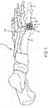
- FIG. 1 is a diagram illustrating prosthetic joint device 10 implanted in foot 12 at first metatarsophalangeal joint (MTPJ1) 14.
- Foot 12 includes five digitorum bones that each include one or both of a distal and medial phalange bone, a proximal phalange bone and a metatarsal phalange bone.
- first metatarsophalangeal joint 14 includes distal phalange bone 16, proximal phalange bone 18 and metatarsal phalange 20.
- Prosthetic joint device 10 can include flexible spacer 22, first anchor component 24A and second anchor component 24B.
- Prosthetic joint device 10 can be used to reproduce the natural or anatomic operation of a joint between two bones of foot 12.
- prosthetic joint device 10 is used in MTPJ1 14 between proximal phalange bone 18 and metatarsal phalange bone 20, but can be used in any of the digitorum bones of foot 12.
- prosthetic joint device 10 can be used to repair or replace other small-bone joints, such as metacarpal joints of a hand.
- a healthy anatomic MTPJ1 joint includes cartilage that the epiphysis end of each bone (see FIG. 6 ).
- the cartilage along with joint fluid provides a cushion between each bone that also facilitates flexion of the joint.
- the cartilage can become worn or can deteriorate with age, and trauma, thus causing pain and stiffness of the joint.
- Prosthetic joint device 10 can be implanted in the joint to alleviate the pain and restore proper joint flexibility and mobility.
- anchor components 24A and 24B can provide firm anchoring of prosthetic joint device 10 to bones 18 and 20 via osseointegration and flexible spacer 22 can hold MPJ1 14 joint together in the anterior-posterior direction while also providing flexion in a sagittal plane.
- First anchor component 24A and second anchor component 24B can be attached to proximal phalange bone 18 and metatarsal phalange bone 20, respectively.
- components 24A and 24B can be comprised of porous metallic material, such as porous titanium or tantalum.
- Flexible spacer 22 can be positioned between and connected to components 24A and 24B.
- spacer 22 can comprise a polymeric component having anterior-posterior aligned fibers that can be embedded in a polymeric matrix to provide flexibility to the device.
- FIG. 2 is a schematic diagram illustrating prosthetic joint device 30 including flexible spacer 32 connecting first anchor component 34A and second anchor component 34B, which are connected to proximal phalange bone 18 and metatarsal phalange bone 20, respectively.
- device 30, and other embodiments of the present application can include two opposing anchor components, such as components 34A and 34B, that can be used to provide attachment to bone and a central cushion component, such as flexible spacer 32, that can provide coupling of and flexibility to the joint.
- device 30 can be manufactured in multiple processes such that device 30 is a single integrated body of multiple materials.
- flexible spacer 32 can be produced using an additive manufacturing process or molding process using a polymer, while anchor components 34A and 34B can be produced using a separate additive manufacturing process using a metal.
- prosthetic joint device 30 can be comprised of a single monolithic structure or a plurality of different components attached together.
- Prosthetic joint device 30 can also be comprised of a single type of material or a plurality of material types.
- device 30 can be manufactured in a single process such that device 30 is a monolithic body of only a polymeric material.
- device 30 can be manufactured using a single process such that device 30 comprises a monolithic body of multiple materials.
- Additive manufacturing processes such as three-dimensional (3D) printing techniques, (such as electron beam or laser additive manufacturing) can be used to produce porous metallic structures of titanium alloys or tantalum, having geometries conducive to osteointegration and can additionally produce the intricacies of elongate fibers in a desired orientation.
- additive manufacturing processes allow one or more of the components of device 30 to be built directly onto one of more of the other components.
- first anchor component 34A and second anchor component can be made of a porous metallic material to facilitate attachment to bone
- flexible spacer 32 can be made of a polymeric material including fibers to facilitate flexing.
- the specific shape and geometry of anchor components 34A and 34B and spacer 32 can vary based on design needs.
- anchor components 34A and 34B and spacer 32 can have circular, rectangular, square or polygonal cross-sectional profiles.
- anchor components 34A and 34B and spacer 32 have hexagonal cross-sectional profiles, as shown in FIGS. 4 and 5 .
- Hexagonal profiles can facilitate implantation into bone by providing adequate planar surface areas for bone contact and also providing edges for resisting rotation within the bone.
- FIG. 3 is a schematic diagram illustrating prosthetic joint device 40 of the present disclosure including flexible spacer 42 and anchor components 44A and 44B coupled between proximal phalange bone 18 and metatarsal phalange bone 20.
- Flexible spacer 42 can comprise elongate fibers 46, matrix 48 and interdigitation zones 50A and 50B.
- Anchor component 44A can comprise base 52A and fixation pegs 54A and 56A.
- Anchor component 44B can comprise base 52B and fixation pegs 54B and 56B.
- Base 52A of anchor component 44A can comprise a disk-like body for supporting flexible spacer 42 and facilitating attachment to proximal phalange bone 18.
- Posterior surface 58A can be flat or substantially flat to provide a base upon which interdigitation zone 50A can be located and built-up from.
- anterior surface 60A can be flat to enhance bone contact with proximal phalange bone 18, which can be resected to provide a flat bone surface.
- Fixation pegs 54A and 56A can extend from anterior surface 60A in a location to allow fixation pegs 54A and 56A to be inserted into cancellous bone of proximal phalange bone 18. Fixation pegs 54A and 56A therefore increase the surface area of anchor component 44A in contact with bone to increase osseointegration, as well as provide initial fixation of anchor component 44A with bone 18.
- Base 52B of anchor component 44B can comprise a disk-like body for supporting flexible spacer 42 and facilitating attachment to metatarsal phalange bone 20.
- Anterior surface 60B can be flat or substantially flat to provide a base upon which interdigitation zone 50B can be located and built-up from.
- posterior surface 58B can be flat to enhance bone contact with metatarsal phalange bone 20, which can be resected to provide a flat bone surface.
- Fixation pegs 54B and 56B can extend from posterior surface 58B in a location to allow fixation pegs 54B and 56B to be inserted into cancellous bone of metatarsal phalange bone 20. Fixation pegs 54B and 56B therefore increase the surface area of anchor component 44B in contact with bone to increase osseointegration, as well as provide initial fixation of anchor component 44B with bone 20.
- Anchor components 44A and 44B can be identical in geometry and can be interchangeable such that anterior surfaces 60A and 60B and posterior surfaces 58A and 58B can be reversed, respectively.
- bases 52A and 52B can have a variety of cross-sectional profiles.
- the cross-sectional profiles of fixation pegs 54A, 56A, 54B and 56B can have a variety of cross-sectional profiles, such as circular, rectangular, square, polygonal, hexagonal and ribbed.
- posterior surface 58A and anterior surface 60B can be flat to facilitate adhesion with interdigitation zones 50A and 50B, respectively.
- Interdigitation zones 50A and 50B can comprise solid bodies of material that can facilitate coupling of elongate fibers 46 to bases 52A and 52B, respectively.
- interdigitation zone 50A can comprise a disk of material having anterior surface 62A that can be fused into pores of base 52A and posterior surface 64A from which fibers 46 can integrally extend.
- interdigitation zone 50B can comprise a disk of material having posterior surface 64B that can be fused into pores of base 52B and anterior surface 62B from which fibers 46 can integrally extend.
- Fibers 46 can extend from first interdigitation zone 50A to second interdigitation zone 50B. In an example, all of fibers 46 are parallel or substantially parallel to each other. Fibers 46 can extend parallel to axis A of device 40. Axis A can extend along the longitudinal centers of anchor components 44A and 44B, which can coincide with the anatomic centers of bones 18 and 20. Material of matrix 48 can be sandwiched between interdigitation zones 50A and 50B and filled-in between fibers 46. Material of matrix 48 can be in contact with fibers 46, but not bonded thereto. Coupling of interdigitation zones 50A and 50B to bases 52A and 52B, respectively, and fibers 46 provides axial, anterior-posterior stability and connection of device 40. Fibers 46 additionally permit flexible spacer 42 to bend as material of matrix 48 can slide past and around fibers 46 under deflection. As such, device 40 can replicate the feel and flexibility of an anatomic joint.
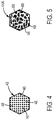
- FIG. 4 is a cross-sectional view of flexible spacer 42 of FIG. 3 showing a plurality of fibers 46 disposed in matrix 48.
- the size and spacing of fibers 46 relative to the depicted cross-section are not drawn to scale, and are shown for illustrative purposes.
- Fibers 46 can have circular cross-sectional profiles to facilitate bending, but other shapes can be used. In examples, fibers 46 can have diameters in the range of approximately 0.4 nm to approximately 100 nm. In other examples, fibers 46 can have other cross-sectional profiles. Fibers 46 can be separated from each other to provide space for matrix 48. In examples, fibers 46 can be spaced at intervals in the range of approximately 0.01 mm to approximately 2 mm.
- Fibers 46 can be spaced uniformly or asymmetrically or crossed. Crossing and spacing of fibers 46 can be used to adjust stiffness of flexible spacer 42.
- flexible spacer 42 can be more densely spaced near the bottom or inferior side of the device to facilitate bending in the superior direction.
- fibers 46 and matrix 48 can comprise polyethylene material.
- fibers 46 can comprise approximately 20% to approximately 70% of the area of the cross-section. Such a ratio can provide adequate stiffness to flexible spacer 42 for the purposes of compression, tension and torsion, but facilitates bending of flexible spacer 42 in a manner that realistically reproduces operation of a natural joint.
- Matrix 48 can comprise polymeric material that is loosely packed around and amongst fibers 46. In an example, material of matrix 48 form pseudo-tubes round fibers 46 that assist in maintaining fibers 46 separated and provide resistance to axial compressing of fibers 46, but that do not inhibit flexing of fibers 46.
- FIG. 5 is a cross-sectional view of anchor component 44A of FIG. 3 showing a metallic porous structure comprised of struts 66 and voids 68.
- the size and spacing of struts 66 and voids 68 relative to the depicted cross-section are not drawn to scale, and are shown for illustrative purposes.
- struts 66 are configured to provide structural stability to anchor component 44A, while producing voids 68 that reduce the weight of component 44A and provide space for osseointegration with bone and fusion with interdigitation zone 62A ( FIG. 3 ).
- struts 66 and voids can reproduce the geometries of anatomic bone.
- struts 66 and voids 68 can have other or synthetic geometries.
- Anchor component 44A can be formed of a suitable material that promotes bone ingrowth and is biocompatible, such as porous metallic material, or a porous tantalum material having a porosity of approximately 20% - 80% and pores sizes of approximately 50 ⁇ m - 600 ⁇ m for example, or within any range defined between any pair of the foregoing values.
- a suitable material that promotes bone ingrowth and is biocompatible such as porous metallic material, or a porous tantalum material having a porosity of approximately 20% - 80% and pores sizes of approximately 50 ⁇ m - 600 ⁇ m for example, or within any range defined between any pair of the foregoing values.
- An example of highly porous tantalum and titanium alloy materials are Trabecular MetalTM and OsseoTiTM generally available from Zimmer Biomet, of Warsaw, Ind. Both materials are trademarks of Zimmer Biomet.
- Anchor component 44A can be formed by a plurality of different processes.
- such a material may be formed from a reticulated vitreous carbon foam substrate which is infiltrated and coated with a biocompatible metal, such as tantalum, by a chemical vapor deposition (CVD) process in the manner disclosed in detail in U.S. Pat. No. 5,282,861 to Kaplan , the disclosure of which is expressly incorporated herein by reference in its entirety for all purposes.
- CVD chemical vapor deposition
- other metals such as niobium, or alloys of tantalum and niobium with one another or with other metals may also be used.
- the open cell metal structures can be fabricated using the tantalum metal film and carbon substrate combination, with the film deposited by CVD, which mimics bone closely in having struts 66 interconnected to form open spaces or voids 68.
- anchor component 44A and other prosthetic components described herein with metallic porous structures including struts and voids and the like, such as the ones described herein, can be provided by any number of suitable three-dimensional, porous structures, and these structures can be formed with one or more of a variety of materials including but not limited to polymeric materials which are subsequently pyrolyzed, metals, metal alloys, ceramics.
- a highly porous three-dimensional structure will be fabricated using a selective laser sintering (SLS) or other additive manufacturing-type process such as direct metal laser sintering.
- SLS selective laser sintering
- a three-dimensional porous article is produced in layer-wise fashion from a laser-fusible powder, e.g., a polymeric material powder or a single-component metal powder, that is deposited one layer at a time.
- the powder is fused, remelted or sintered, by the application of laser energy that is directed to portions of the powder layer corresponding to a cross section of the article.
- an additional layer of powder is deposited, and a further fusing step is carried out, with fused portions or lateral layers fusing so as to fuse portions of previous laid layers until a three-dimensional article is complete.
- a laser selectively fuses powdered material by scanning cross-sections generated from a 3-D digital description of the article, e.g., from a CAD file or scan data, on the surface of a powder bed. Net shape and near net shape constructs are infiltrated and coated in some instances.
- a three-dimensional porous structure will be particularly suited for contacting bone and/or soft tissue, and in this regard, can be useful as a bone substitute and as cell and tissue receptive material, for example, by allowing tissue to grow into the porous structure over time to enhance fixation (i.e., osseointegration) between the structure and surrounding bodily structures, for example, to provide a matrix approximating natural cancellous bone or other bony structures.
- a three-dimensional porous structure, or any region thereof may be fabricated to virtually any desired density, porosity, pore shape, and pore size (e.g., pore diameter). Such structures therefore can be isotropic or anisotropic.
- Such structures can be infiltrated and coated with one or more coating materials.
- any suitable metal may be used including any of those disclosed herein such as tantalum, titanium, a titanium alloy, cobalt chromium, cobalt chromium molybdenum, tantalum, a tantalum alloy, niobium, or alloys of tantalum and niobium with one another or with other metals.
- a three-dimensional porous structure may be fabricated to have a substantial porosity, density, pore shape and/or void (pore) size throughout, or to comprise at least one of pore shape, pore size, porosity, and/or density being varied within the structure.
- a three-dimensional porous structure to be infiltrated and coated may have a different pore shape, pore size and/or porosity at different regions, layers, and surfaces of the structure.
- a non-porous or essentially non-porous base substrate will provide a foundation upon which a three-dimensional porous structure will be built and fused thereto using a selective laser sintering (SLS) or other additive manufacturing-type process.
- SLS selective laser sintering
- Such substrates can incorporate one or more of a variety of biocompatible metals such as titanium, a titanium alloy, cobalt chromium, cobalt chromium molybdenum, tantalum, or a tantalum alloy.
- anchor component 44A can comprise titanium that is fabricated using a rapid manufacturing process.
- the rapid manufacturing process can comprise an additive manufacturing process, such as a powder deposition process.
- very thin layers e.g., layers that are only as thick as several levels of particles of the powdered titanium
- the unsolidified particles can be left to support the next layer of powder.
- a laser can be used to selectively melt portions of the powdered titanium layer that will form anchor component 44A.
- a new layer of titanium powder particles can be laid down on top of the previous, partially solidified layer and an additional solidification process can occur.
- the steps can be repeated until anchor component 44A is built-up from one end to the other.
- the unsolidified particles can then be removed.
- Other types of rapid manufacturing processes can be used to fabricate prosthetic joint device 40, such as 3D printing processes.
- struts 66 can be made to have any desired shape, size, number and aggregate strength and density in order to generate sufficient bonding strength to survive implantation and operation of anchor component 44A, while permitting infusion of bone and polymer material from interdigitation zone 50A, as described herein.
- FIG. 6 is a diagram illustrating natural anatomy 70 of first metatarsophalangeal joint 14 of FIG. 1 , which can comprise proximal phalange bone 18 and metatarsal phalange bone 20.
- Anatomy 70 can include articular cartilage pads 72A and 72B located on ends of bones 18 and 20, respectively.
- the joint capsule can be filled with synovial fluid 74 enclosed within synovial membrane 76.
- cartilage pads 72A and 72B can become worn down and/or hardened, potentially resulting in pain and discomfort for the patient, as ends of bones 18 and 20 rub against each other.
- cartilage pads 72A and 72B can be desirable to reproduce the natural feel and action of cartilage pads 72A and 72B with a prosthetic joint device configured according to the embodiments and examples described herein.
- a prosthetic joint device configured according to the embodiments and examples described herein.
- an incision can be made through skin 78 and synovial membrane 76 to expose cartilage pads 72A and 72B.
- Joint 14 can be flexed to expose the opposing ends of bones 18 and 20, as shown in FIG. 7 .
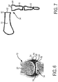
- FIG. 7 is a diagram illustrating positioning of resected bones 18 and 20 for the implantation of prosthetic joint device 40 of the present disclosure into first metatarsophalangeal joint 14.
- Proximal phalange bone 18 can be flexed to be substantially transverse to metatarsal phalange bone 20.
- Distal end 80 of metatarsal phalange bone 20 can be resected to form planar anterior surface 82.
- Proximal end 84 of proximal phalange bone 18 can be resected to form planar posterior surface 86.
- cartilage pads 72A and 72B can be removed and cancellous bone within bones 18 and 20 can become exposed at surfaces 82 and 86 within the hard, cortical walls of bones 18 and 20.
- Prosthetic joint device 40 can be flexed at flexible spacer 42 so that fixation pegs 54B and 56B can be press fit into the cancellous bone of surface 82 and fixation pegs 54A and 56A can be press fit into the cancellous bone of surface 86.
- FIG. 8 is a diagram illustrating implanted prosthetic joint device 40 of the present disclosure implanted into resected bones 18 and 20 of FIG. 7 .
- Prosthetic joint device 40 can include first anchor component 44A, second anchor component 44B and flexible spacer 42.
- Fixation pegs 54A and 56A of first anchor component 44A can be inserted into cancellous bone of planar posterior surface 86 such that anterior surface 60A of base 52A abuts flush against planar posterior surface 86.
- Fixation pegs 54B and 56B of second anchor component 44B can be inserted into cancellous bone of planar anterior surface 82 such that posterior surface 58B of base 52B abuts flush against planar anterior surface 82.
- Flush engagement between surface 86 and surface 60A and surface 82 and surface 58B, respectively, can facilitate stability of prosthetic joint device 40 and can promote bone ingrowth into anchor components 44A and 44B.
- Prosthetic joint device 40 can be sized to fit within MPJ1 14.
- prosthetic joint device 40 can come in a single size that is configured to fit most or all of the different sizes of bones of the general population.
- prosthetic joint device 40 can be come in a plurality of sizes, e.g., small, medium and large, to allow for semi-custom sizing.
- prosthetic joint device can be custom sized for patient-specific applications, such as by measuring the size of bones 18 and 20 from preoperative imaging.
- the length of prosthetic joint device 40 between surfaces 58B and 60A can be approximately equal to the length of the resected portions of bones 18 and 20 plus the thicknesses of cartilage pads 72A and 72B, such as the average of the general adult population.
- the diameter of bases 52A and 52B can be sized to be approximately equal to the diameter of bones 18 and 20 at joint 14, such as the average of the general adult population.
- FIG. 9 is a line diagram illustrating steps of method 100 for manufacturing a prosthetic joint device, such as prosthetic joint device 40, of the present disclosure.
- the size of joint 14 ( FIG. 1 ) can be determined.
- the diameters of proximal phalange bone 18 and metatarsal phalange bone 20 can be measured from pre-operative imaging of joint 14.
- the pre-operative imaging can include x-ray images, CT images, MRI images and the like, as well as two-dimensional and three-dimensional computer-generated models derived from the pre-operative imaging. From such measurements, the diameters for bases 52A and 52B ( FIG. 3 ) can be determined.
- the joint length e.g., the thickness of cartilage pads 72A and 72B, can be measured.
- the combined length of flexible spacer 42 and bases 52A and 52B can be determined.
- the measured size of joint 14 can be used to custom manufacture prosthetic joint device 40 to fit a specific patient, or can be used to select from a range of predetermined sizes of prosthetic joint device 40.
- Step 102 can be an optional step.
- prosthetic joint device 40 can be manufactured from anatomic data of the general adult population and can be configured for use in the general adult population without measurement.
- measurement of joint 14 can be conducted intraoperatively by a surgeon or other person to determine a size from premanufactured prosthetic joint devices.
- porous anchor components 44A and 44B can be manufactured, such as by using a three-dimensional ("3D") printing process.
- 3D three-dimensional
- a selective laser sintering process can be used to build up bases 52A and 52B and fixation pegs 54A - 56B.
- Such components can include struts 66 and voids 68.
- Components 44Aand 44B can be manufactured from a variety of materials, such as polymeric material and metallic material.
- Bases 52A and 52B can be made to sizes, e.g., length and diameter, based on measurements taken at step 102.
- components 44A and 44B are made from titanium alloys, stainless steel alloys and tantalum alloys.
- flexible spacer 42 can be manufactured, such as by using a 3D printing process or molding process or combination of both.
- a fused filament fabrication process can be used to build up interdigitation zones 50A and 50B, fibers 46 and matrix 48.
- one of interdigitation zones 50A and 50B can be directly built up on top of one of bases 52A and 52B, respectively.
- polymeric material of interdigitation zone 50A can be deposited onto and/or melted into voids 68 of base 52A, thereby causing adhesion of interdigitation zone 50A to base 52A.
- Interdigitation zone 50A can be built up to a sufficient thickness to cover or substantially the desired surface area of base 52A.
- interdigitation zone 50A can be made from a polymeric material, such as polyethylene.
- intercalated polymer of flexible spacer 42 between two metallic scaffolds formed by porous anchor components 44A and 44B can be 3D printed using a polymer and antibiotics powder mixture.
- the antibiotic can be eluted out of the polymer material and from the implant into the patient to, for example, prevent and treat possible infection.
- the antibiotic powder can be azithromycin, amoxicillin, gentamicine or other similar medicants.
- fibers 46 can be built-up onto interdigitation zone 50A. Fibers 46 can be built integrally with interdigitation zone 50A.
- material of matrix 48 can be deposited around fibers 46. Fibers 46 and matrix 48 can be simultaneously built-up on top of interdigitation zone 50A to the desired length. Fibers 46 and matrix 48 can be made to a length based on measurements taken at step 102. The material of matrix 48 can be positioned around, without attaching to, fibers 46 to facilitate flexing of flexible spacer 42.
- fibers 46 and matrix 48 can be made from a polymeric material, such as polyethylene.
- fibers 46 and matrix 48 can be made from the same or different materials as each other.
- interdigitation zone 50B can be built-up on ends of fibers 46 and on top of matrix 48.
- a layer of the material of flexible component 42 can be formed to tie-up ends of fibers 46 and form a base for joining with second anchor component 44B.
- interdigitation zone 50B can be made from a polymeric material, such as polyethylene.
- interdigitation zone 50B and second anchor component 44B can be attached to each other.
- interdigitation zone 50B can be built-up to the desired thickness and anchor component 44B can be attached to interdigitation zone 50B, such as by being pushed into the material of interdigitation zone 50B to cause the material to penetrate into voids 68.
- interdigitation zone 50B can be built-up directly on base 52B and attached to fibers 46 and matrix 48.
- Steps 102 through 114 describe example method steps for forming prosthetic joint devices to include a plurality of elongate fibers.
- elongate fibers can be built up in a parallel or criss-crossed axial manner to extend between anchor components.
- the elongate fibers can be continuous between the anchor components to provide axial or anterior-posterior strength to the device.
- the elongate fibers have diameters such that the device can readily flex in the sagittal plane.
- the presence of matrix material alongside the elongate fibers provides stabilization to the elongate fibers to prevent buckling of the device, e.g., collapsing together of the device in the anterior-posterior direction.
- Such a fiber and matrix composition can be produced with additive manufacturing techniques described herein. However, in other examples, manufacturing processes that can produce the fiber and matrix composition described herein can be used, such as molding processes.
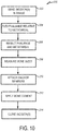
- FIG. 10 is a line diagram illustrating steps of method 200 for implanting a prosthetic joint device, such as prosthetic joint device 40, of the present disclosure.
- Steps 202 - 214 provide a high-level overview of steps that can be taken to implant prosthetic joint device 40 and are not intended to be an exhaustive listing. In other examples, other steps can be used.
- incisions in tissue of the patient can be made to expose bones 18 and 20 of MTPJ1 14.
- skin 78 and capsule 76 can be cut open to expose cartilage pads 72A and 72B, if said pads are not worn away from osteoarthritis, as shown in FIG. 6 .
- MTPJ1 14 can be flexed by the surgeon or other personal to expose the distal ends of proximal phalange bone 18 and metatarsal phalange bone 20, as shown in FIG. 7 .
- cartilage pads 72A and 72B can be exposed and distal end 80 and proximal end 84 ( FIG. 7 ) are readily viewable by the surgeon.
- bones 18 and 20 can be resected to form planar posterior surface 86 and planar anterior surface 82, respectively, as shown in FIG. 7 .
- Bones 18 and 20 can be resected to form flat or planar surfaces against which surfaces of anchor components 44A and 44B can abut. Additionally, bones 18 and 20 can be resected to expose cancellous bone into which fixation pegs 54A - 56B ( FIG. 3 ) can be implanted.
- any desired measuring of bones 18 and 20, surfaces 86 and 82 and the gap between surfaces 86 and 82 for the sizing of the prosthetic joint component can be conducted. For example, if non-custom or standard implants are to be used, a surgeon can measure or observe the size of bones 18 and 20 intraoperatively to determine which size of prosthetic joint device 40 is to be used from a set of standard sized devices.
- any anchor members of prosthetic joint device 40 can be connected to bones 18 and 20.
- fixation pegs 54A and 56A of anchor component 44A can be inserted into cancellous bone at surface 86 at bone 18, and fixation pegs 54B and 56B of anchor component 44B can be inserted into cancellous bone as surface 82 of bone 20.
- Flexible spacer 42 can be flexed or bent by the surgeon to simultaneously attach all of fixation pegs 54A - 56B. Thereafter, tension on flexible spacer can be released and fibers 46 of flexible spacer can relax and return to the natural unflexed condition so that bone 18 can be moved into axial alignment with bone 20, as shown in FIG. 8 .
- any bone cement can be applied to anchor components 44A and 44B if desired.
- Application of bone cement can be optional if a surgeon can determine that adequate bone material exists to support fixation pegs 54A - 56B.
- any other observations of the fit of prosthetic joint device 40 or the flexion of the repaired joint 14 can be observed and evaluated after implantation.
- any incisions made at step 202 can be closed-up, if desired or deemed appropriate by the surgeon.
- FIG. 11 is a schematic diagram illustrating prosthetic joint implant 300 of the present disclosure including electronic circuit 306.
- Electronic circuit 306 can be in communication with reader 302 and computer system 304.
- Prosthetic joint implant 300 can comprise polymer layer 308 disposed between porous scaffolds 310A and 310B.
- Electronic circuit 306 can comprise capacitor layers 312A and 312B, insulator 314 and resistor 316. Components of prosthetic joint implant 300 are not drawn to scale.
- Porous scaffolds 310A and 310B and polymer layer 308 can be configured according to the devices described herein.
- Electronic circuit 306 can comprise an active version of a prosthetic joint implant that can communicate information from the patient.
- Electronic circuit 306 can include one or more capacitors formed by capacitor layers 312A and 312B and insulator 314, as well as one or more of resistor 316 and other electronic components.
- the electronic components can be 3D printed onto the interfaces between metallic porous scaffolds 310A and 310B and polymer layer 308 to measure stresses and strains during activities of daily living.
- Capacitor layers 312A and 312B can comprise conducting plates that can be made of tantalum, silver or niobium, while insulator 314 can comprise a dielectric that can be made of polymer or ceramic materials. Resistor 316 can be printed from carbon and ceramic powders.
- Information or data relating to the measurements taken by electronic circuit 306 can be transmitted to reader 302.
- Reader 302 can be configured to wirelessly communicate with electronic circuit 306.
- reader 302 can additionally have writing capabilities to send information to electronic circuit 306.
- electronic circuit 306 can include a receiver and an electronic memory device.
- patient-specific information can be written to prosthetic joint implant 300.
- Information obtained from electronic circuit 306 can be transmitted to computer system 304 where the data can be stored and analyzed. The stresses and strains can be analyzed to determine the condition of prosthetic joint implant 300 and to evaluate the lifestyle of the patient.
- Method examples described herein can be machine or computer-implemented at least in part. Some examples can include a computer-readable medium or machine-readable medium encoded with instructions operable to configure an electronic device to perform methods as described in the above examples.
- An implementation of such methods can include code, such as microcode, assembly language code, a higher-level language code, or the like. Such code can include computer readable instructions for performing various methods. The code may form portions of computer program products. Further, in an example, the code can be tangibly stored on one or more volatile, non-transitory, or non-volatile tangible computer-readable media, such as during execution or at other times.
- Examples of these tangible computer-readable media can include, but are not limited to, hard disks, removable magnetic disks, removable optical disks (e.g., compact disks and digital video disks), magnetic cassettes, memory cards or sticks, random access memories (RAMs), read only memories (ROMs), and the like.
Landscapes
- Health & Medical Sciences (AREA)
- Orthopedic Medicine & Surgery (AREA)
- Engineering & Computer Science (AREA)
- Heart & Thoracic Surgery (AREA)
- Life Sciences & Earth Sciences (AREA)
- Oral & Maxillofacial Surgery (AREA)
- Transplantation (AREA)
- Biomedical Technology (AREA)
- Veterinary Medicine (AREA)
- Vascular Medicine (AREA)
- Cardiology (AREA)
- Animal Behavior & Ethology (AREA)
- General Health & Medical Sciences (AREA)
- Public Health (AREA)
- Manufacturing & Machinery (AREA)
- Physics & Mathematics (AREA)
- Geometry (AREA)
- Prostheses (AREA)
Applications Claiming Priority (1)
| Application Number | Priority Date | Filing Date | Title |
|---|---|---|---|
| US201862724273P | 2018-08-29 | 2018-08-29 |
Publications (3)
| Publication Number | Publication Date |
|---|---|
| EP3653174A2 true EP3653174A2 (de) | 2020-05-20 |
| EP3653174A3 EP3653174A3 (de) | 2020-10-28 |
| EP3653174B1 EP3653174B1 (de) | 2024-08-07 |
Family
ID=67809363
Family Applications (1)
| Application Number | Title | Priority Date | Filing Date |
|---|---|---|---|
| EP19194431.3A Active EP3653174B1 (de) | 2018-08-29 | 2019-08-29 | Gelenkersatzvorrichtung für das metatarsophalangealgelenk |
Country Status (3)
| Country | Link |
|---|---|
| US (2) | US11076964B2 (de) |
| EP (1) | EP3653174B1 (de) |
| CN (1) | CN110870812B (de) |
Families Citing this family (14)
| Publication number | Priority date | Publication date | Assignee | Title |
|---|---|---|---|---|
| EP2903567B1 (de) * | 2012-10-02 | 2017-08-09 | McCullen, Seth | Implantierbare vorrichtungen für muskuloskelettäre reparatur und regeneration |
| EP3618774A4 (de) | 2017-05-02 | 2021-01-27 | McCullen, Seth | Verbundgelenkimplantat |
| US11076964B2 (en) | 2018-08-29 | 2021-08-03 | Zimmer, Inc. | Metarsophalangeal joint replacement device and methods |
| US11986251B2 (en) | 2019-09-13 | 2024-05-21 | Treace Medical Concepts, Inc. | Patient-specific osteotomy instrumentation |
| US12490992B2 (en) | 2019-09-13 | 2025-12-09 | Treace Medical Concepts, Inc. | Patient-specific surgical methods and instrumentation |
| CA3150081A1 (en) | 2019-09-13 | 2021-03-18 | Adam D. Perler | Patient-specific surgical methods and instrumentation |
| TWI724938B (zh) * | 2020-07-08 | 2021-04-11 | 可成生物科技股份有限公司 | 人體植入物 |
| EP4023179B1 (de) * | 2020-12-30 | 2025-07-02 | Stryker European Operations Limited | System mit einer schaumstruktur und einer chirurgischen fixierungsvorrichtung |
| AU2023242748A1 (en) * | 2022-04-01 | 2024-10-17 | Djit Medtech, Inc. | Stemless semi-constrained implantable joint replacement device |
| US20250107896A1 (en) * | 2023-10-01 | 2025-04-03 | Djit Medtech, Inc. | Anchor for an Implantable Joint Replacement Device |
| US20250107900A1 (en) * | 2023-10-01 | 2025-04-03 | Djit Medtech, Inc. | Flexible Connector for an Implantable Joint Replacement Device |
| US20250191499A1 (en) * | 2023-12-07 | 2025-06-12 | Ricardo Vega | Method for Integrated 3D Printing of Articulated Models with Preserved Spatial Kinematics and Functional Movement |
| US12290445B1 (en) | 2024-05-03 | 2025-05-06 | Djit Medtech, Inc. | Joint implants with bone interface connectors |
| US12427023B1 (en) | 2024-09-05 | 2025-09-30 | Djit Medtech, Inc. | Joint implants with interface surfaces having registration features |
Citations (7)
| Publication number | Priority date | Publication date | Assignee | Title |
|---|---|---|---|---|
| US5282861A (en) | 1992-03-11 | 1994-02-01 | Ultramet | Open cell tantalum structures for cancellous bone implants and cell and tissue receptors |
| US5480447A (en) | 1992-12-15 | 1996-01-02 | International Polymer Engineering, Inc. | Joint implant |
| US5879396A (en) | 1993-12-28 | 1999-03-09 | Walston; D. Kenneth | Joint prosthesis having PTFE cushion |
| US6007580A (en) | 1995-06-13 | 1999-12-28 | Bionx Implants Oy | Joint prosthesis |
| US8920453B2 (en) | 2008-06-24 | 2014-12-30 | Extremity Medical, Llc | Fixation system, an intramedullary fixation assembly and method of use |
| US20170367838A1 (en) | 2015-01-13 | 2017-12-28 | University Of Washington | Devices and methods for metatarsophalangeal arthroplasty procedures |
| US9907663B2 (en) | 2015-03-31 | 2018-03-06 | Cartiva, Inc. | Hydrogel implants with porous materials and methods |
Family Cites Families (13)
| Publication number | Priority date | Publication date | Assignee | Title |
|---|---|---|---|---|
| US3593342A (en) | 1969-01-27 | 1971-07-20 | Cutter Lab | Prosthetic joint |
| US3886600A (en) | 1971-07-15 | 1975-06-03 | Cutter Lab | Joint prosthesis |
| FR2484826B1 (fr) | 1980-06-19 | 1985-10-04 | Gauthier Georges | Perfectionnement aux protheses articulaires |
| EP0057597B1 (de) | 1981-01-30 | 1985-06-26 | Oec Europe Limited | Gelenkprothese |
| SE525131C2 (sv) | 2001-01-15 | 2004-12-07 | Artimplant Ab | Implantat för rekonstruktion av leder |
| US20030097180A1 (en) | 2001-11-20 | 2003-05-22 | Pertti Tormala | Joint prosthesis |
| US20050116400A1 (en) * | 2003-11-14 | 2005-06-02 | White Moreno J. | Non-linear fiber/matrix architecture |
| US8663326B2 (en) * | 2007-12-13 | 2014-03-04 | Said G. Osman | Biologic artificial bone |
| AU2011314157A1 (en) | 2010-09-29 | 2013-05-09 | Zimmer, Inc. | Pyrolytic carbon implants with porous fixation component and methods of making the same |
| ITUD20120059A1 (it) * | 2012-04-06 | 2013-10-07 | Limacorporate Spa | Elemento protesico per estremita' ossee quali dita o denti e relativo procedimento di realizzazione |
| US9763800B2 (en) * | 2015-03-18 | 2017-09-19 | Biomet C. V. | Implant configured for hammertoe and small bone fixation |
| US10687952B2 (en) | 2018-01-08 | 2020-06-23 | Russell D. Petranto | Flexible, cannulated implants for the hand and foot and methods of implanting flexible implants |
| US11076964B2 (en) | 2018-08-29 | 2021-08-03 | Zimmer, Inc. | Metarsophalangeal joint replacement device and methods |
-
2019
- 2019-08-28 US US16/553,559 patent/US11076964B2/en active Active
- 2019-08-29 CN CN201910806027.2A patent/CN110870812B/zh active Active
- 2019-08-29 EP EP19194431.3A patent/EP3653174B1/de active Active
-
2021
- 2021-07-07 US US17/369,424 patent/US11779467B2/en active Active
Patent Citations (7)
| Publication number | Priority date | Publication date | Assignee | Title |
|---|---|---|---|---|
| US5282861A (en) | 1992-03-11 | 1994-02-01 | Ultramet | Open cell tantalum structures for cancellous bone implants and cell and tissue receptors |
| US5480447A (en) | 1992-12-15 | 1996-01-02 | International Polymer Engineering, Inc. | Joint implant |
| US5879396A (en) | 1993-12-28 | 1999-03-09 | Walston; D. Kenneth | Joint prosthesis having PTFE cushion |
| US6007580A (en) | 1995-06-13 | 1999-12-28 | Bionx Implants Oy | Joint prosthesis |
| US8920453B2 (en) | 2008-06-24 | 2014-12-30 | Extremity Medical, Llc | Fixation system, an intramedullary fixation assembly and method of use |
| US20170367838A1 (en) | 2015-01-13 | 2017-12-28 | University Of Washington | Devices and methods for metatarsophalangeal arthroplasty procedures |
| US9907663B2 (en) | 2015-03-31 | 2018-03-06 | Cartiva, Inc. | Hydrogel implants with porous materials and methods |
Also Published As
| Publication number | Publication date |
|---|---|
| CN110870812A (zh) | 2020-03-10 |
| US11779467B2 (en) | 2023-10-10 |
| EP3653174B1 (de) | 2024-08-07 |
| EP3653174A3 (de) | 2020-10-28 |
| US20200069434A1 (en) | 2020-03-05 |
| US11076964B2 (en) | 2021-08-03 |
| CN110870812B (zh) | 2021-12-07 |
| US20210330468A1 (en) | 2021-10-28 |
Similar Documents
| Publication | Publication Date | Title |
|---|---|---|
| US11779467B2 (en) | Metarsophalangeal joint replacement device and methods | |
| US11744716B2 (en) | Intervertebral implants | |
| US11065126B2 (en) | Interbody implants and optimization features thereof | |
| JP6916290B2 (ja) | モジュール式増強コンポーネント | |
| EP2772230B1 (de) | Fusionsprothese für den zweiten halswirbel | |
| US20210338454A1 (en) | 3d printed osteogenesis scaffold | |
| US6533818B1 (en) | Artificial spinal disc | |
| AU2010200881B2 (en) | Interbody fusion device | |
| US9034048B2 (en) | Orthopaedic implants and methods of forming implant structures | |
| CN101128166A (zh) | 具有提高的显像性和耐磨性的基于工程复合材料的植入物 | |
| US11324497B2 (en) | Step staple for fracture fixation | |
| Mehboob | Biomechanical performance evaluation of composite metamaterial implant with 3D printing approach for lumbar interbody fusion surgery: a finite element study | |
| EP4241738A1 (de) | Nicht-polygonale poröse struktur | |
| US20250281112A1 (en) | A surgical implant | |
| WO2021236646A1 (en) | 3d printed osteogenesis scaffold | |
| EP4523660A1 (de) | Implantatsystem für oberarmknochen-rettung | |
| Naghavi | Modelling and in vitro evaluation of customised Ti6Al4V and PEEK hip implants for improving osseointegration and reducing stress shielding | |
| Ramakrishna | Studies on Spinal Fusion From Computational Modelling to'Smart'Implants | |
| CN115813620A (zh) | 一种3d打印颈椎椎间融合器的设计方法和制备方法 | |
| CN110368149A (zh) | 椎间盘假体 | |
| French | The investigation into modes of failure of total hip replacements | |
| MX2008004022A (en) | Artificial intervertebral disc |
Legal Events
| Date | Code | Title | Description |
|---|---|---|---|
| PUAI | Public reference made under article 153(3) epc to a published international application that has entered the european phase |
Free format text: ORIGINAL CODE: 0009012 |
|
| STAA | Information on the status of an ep patent application or granted ep patent |
Free format text: STATUS: THE APPLICATION HAS BEEN PUBLISHED |
|
| AK | Designated contracting states |
Kind code of ref document: A2 Designated state(s): AL AT BE BG CH CY CZ DE DK EE ES FI FR GB GR HR HU IE IS IT LI LT LU LV MC MK MT NL NO PL PT RO RS SE SI SK SM TR |
|
| AX | Request for extension of the european patent |
Extension state: BA ME |
|
| RIC1 | Information provided on ipc code assigned before grant |
Ipc: A61F 2/30 20060101ALI20200618BHEP Ipc: A61F 2/42 20060101AFI20200618BHEP |
|
| PUAL | Search report despatched |
Free format text: ORIGINAL CODE: 0009013 |
|
| AK | Designated contracting states |
Kind code of ref document: A3 Designated state(s): AL AT BE BG CH CY CZ DE DK EE ES FI FR GB GR HR HU IE IS IT LI LT LU LV MC MK MT NL NO PL PT RO RS SE SI SK SM TR |
|
| AX | Request for extension of the european patent |
Extension state: BA ME |
|
| RIC1 | Information provided on ipc code assigned before grant |
Ipc: A61F 2/30 20060101ALI20200922BHEP Ipc: A61F 2/42 20060101AFI20200922BHEP |
|
| STAA | Information on the status of an ep patent application or granted ep patent |
Free format text: STATUS: REQUEST FOR EXAMINATION WAS MADE |
|
| 17P | Request for examination filed |
Effective date: 20210428 |
|
| RBV | Designated contracting states (corrected) |
Designated state(s): AL AT BE BG CH CY CZ DE DK EE ES FI FR GB GR HR HU IE IS IT LI LT LU LV MC MK MT NL NO PL PT RO RS SE SI SK SM TR |
|
| GRAP | Despatch of communication of intention to grant a patent |
Free format text: ORIGINAL CODE: EPIDOSNIGR1 |
|
| STAA | Information on the status of an ep patent application or granted ep patent |
Free format text: STATUS: GRANT OF PATENT IS INTENDED |
|
| INTG | Intention to grant announced |
Effective date: 20230914 |
|
| GRAJ | Information related to disapproval of communication of intention to grant by the applicant or resumption of examination proceedings by the epo deleted |
Free format text: ORIGINAL CODE: EPIDOSDIGR1 |
|
| STAA | Information on the status of an ep patent application or granted ep patent |
Free format text: STATUS: REQUEST FOR EXAMINATION WAS MADE |
|
| INTC | Intention to grant announced (deleted) | ||
| GRAP | Despatch of communication of intention to grant a patent |
Free format text: ORIGINAL CODE: EPIDOSNIGR1 |
|
| STAA | Information on the status of an ep patent application or granted ep patent |
Free format text: STATUS: GRANT OF PATENT IS INTENDED |
|
| INTG | Intention to grant announced |
Effective date: 20240305 |
|
| GRAS | Grant fee paid |
Free format text: ORIGINAL CODE: EPIDOSNIGR3 |
|
| GRAA | (expected) grant |
Free format text: ORIGINAL CODE: 0009210 |
|
| STAA | Information on the status of an ep patent application or granted ep patent |
Free format text: STATUS: THE PATENT HAS BEEN GRANTED |
|
| AK | Designated contracting states |
Kind code of ref document: B1 Designated state(s): AL AT BE BG CH CY CZ DE DK EE ES FI FR GB GR HR HU IE IS IT LI LT LU LV MC MK MT NL NO PL PT RO RS SE SI SK SM TR |
|
| REG | Reference to a national code |
Ref country code: GB Ref legal event code: FG4D |
|
| REG | Reference to a national code |
Ref country code: CH Ref legal event code: EP |
|
| P01 | Opt-out of the competence of the unified patent court (upc) registered |
Free format text: CASE NUMBER: APP_42045/2024 Effective date: 20240716 |
|
| REG | Reference to a national code |
Ref country code: IE Ref legal event code: FG4D |
|
| REG | Reference to a national code |
Ref country code: DE Ref legal event code: R096 Ref document number: 602019056467 Country of ref document: DE |
|
| REG | Reference to a national code |
Ref country code: LT Ref legal event code: MG9D |
|
| REG | Reference to a national code |
Ref country code: NL Ref legal event code: MP Effective date: 20240807 |
|
| PG25 | Lapsed in a contracting state [announced via postgrant information from national office to epo] |
Ref country code: NO Free format text: LAPSE BECAUSE OF FAILURE TO SUBMIT A TRANSLATION OF THE DESCRIPTION OR TO PAY THE FEE WITHIN THE PRESCRIBED TIME-LIMIT Effective date: 20241107 |
|
| REG | Reference to a national code |
Ref country code: AT Ref legal event code: MK05 Ref document number: 1710096 Country of ref document: AT Kind code of ref document: T Effective date: 20240807 |
|
| PG25 | Lapsed in a contracting state [announced via postgrant information from national office to epo] |
Ref country code: NL Free format text: LAPSE BECAUSE OF FAILURE TO SUBMIT A TRANSLATION OF THE DESCRIPTION OR TO PAY THE FEE WITHIN THE PRESCRIBED TIME-LIMIT Effective date: 20240807 Ref country code: PT Free format text: LAPSE BECAUSE OF FAILURE TO SUBMIT A TRANSLATION OF THE DESCRIPTION OR TO PAY THE FEE WITHIN THE PRESCRIBED TIME-LIMIT Effective date: 20241209 Ref country code: FI Free format text: LAPSE BECAUSE OF FAILURE TO SUBMIT A TRANSLATION OF THE DESCRIPTION OR TO PAY THE FEE WITHIN THE PRESCRIBED TIME-LIMIT Effective date: 20240807 Ref country code: PL Free format text: LAPSE BECAUSE OF FAILURE TO SUBMIT A TRANSLATION OF THE DESCRIPTION OR TO PAY THE FEE WITHIN THE PRESCRIBED TIME-LIMIT Effective date: 20240807 Ref country code: GR Free format text: LAPSE BECAUSE OF FAILURE TO SUBMIT A TRANSLATION OF THE DESCRIPTION OR TO PAY THE FEE WITHIN THE PRESCRIBED TIME-LIMIT Effective date: 20241108 |
|
| PG25 | Lapsed in a contracting state [announced via postgrant information from national office to epo] |
Ref country code: BG Free format text: LAPSE BECAUSE OF FAILURE TO SUBMIT A TRANSLATION OF THE DESCRIPTION OR TO PAY THE FEE WITHIN THE PRESCRIBED TIME-LIMIT Effective date: 20240807 |
|
| PG25 | Lapsed in a contracting state [announced via postgrant information from national office to epo] |
Ref country code: LV Free format text: LAPSE BECAUSE OF FAILURE TO SUBMIT A TRANSLATION OF THE DESCRIPTION OR TO PAY THE FEE WITHIN THE PRESCRIBED TIME-LIMIT Effective date: 20240807 |
|
| PG25 | Lapsed in a contracting state [announced via postgrant information from national office to epo] |
Ref country code: AT Free format text: LAPSE BECAUSE OF FAILURE TO SUBMIT A TRANSLATION OF THE DESCRIPTION OR TO PAY THE FEE WITHIN THE PRESCRIBED TIME-LIMIT Effective date: 20240807 Ref country code: IS Free format text: LAPSE BECAUSE OF FAILURE TO SUBMIT A TRANSLATION OF THE DESCRIPTION OR TO PAY THE FEE WITHIN THE PRESCRIBED TIME-LIMIT Effective date: 20241207 |
|
| PG25 | Lapsed in a contracting state [announced via postgrant information from national office to epo] |
Ref country code: HR Free format text: LAPSE BECAUSE OF FAILURE TO SUBMIT A TRANSLATION OF THE DESCRIPTION OR TO PAY THE FEE WITHIN THE PRESCRIBED TIME-LIMIT Effective date: 20240807 |
|
| PG25 | Lapsed in a contracting state [announced via postgrant information from national office to epo] |
Ref country code: ES Free format text: LAPSE BECAUSE OF FAILURE TO SUBMIT A TRANSLATION OF THE DESCRIPTION OR TO PAY THE FEE WITHIN THE PRESCRIBED TIME-LIMIT Effective date: 20240807 Ref country code: RS Free format text: LAPSE BECAUSE OF FAILURE TO SUBMIT A TRANSLATION OF THE DESCRIPTION OR TO PAY THE FEE WITHIN THE PRESCRIBED TIME-LIMIT Effective date: 20241107 |
|
| PG25 | Lapsed in a contracting state [announced via postgrant information from national office to epo] |
Ref country code: RS Free format text: LAPSE BECAUSE OF FAILURE TO SUBMIT A TRANSLATION OF THE DESCRIPTION OR TO PAY THE FEE WITHIN THE PRESCRIBED TIME-LIMIT Effective date: 20241107 Ref country code: PT Free format text: LAPSE BECAUSE OF FAILURE TO SUBMIT A TRANSLATION OF THE DESCRIPTION OR TO PAY THE FEE WITHIN THE PRESCRIBED TIME-LIMIT Effective date: 20241209 Ref country code: PL Free format text: LAPSE BECAUSE OF FAILURE TO SUBMIT A TRANSLATION OF THE DESCRIPTION OR TO PAY THE FEE WITHIN THE PRESCRIBED TIME-LIMIT Effective date: 20240807 Ref country code: NO Free format text: LAPSE BECAUSE OF FAILURE TO SUBMIT A TRANSLATION OF THE DESCRIPTION OR TO PAY THE FEE WITHIN THE PRESCRIBED TIME-LIMIT Effective date: 20241107 Ref country code: NL Free format text: LAPSE BECAUSE OF FAILURE TO SUBMIT A TRANSLATION OF THE DESCRIPTION OR TO PAY THE FEE WITHIN THE PRESCRIBED TIME-LIMIT Effective date: 20240807 Ref country code: LV Free format text: LAPSE BECAUSE OF FAILURE TO SUBMIT A TRANSLATION OF THE DESCRIPTION OR TO PAY THE FEE WITHIN THE PRESCRIBED TIME-LIMIT Effective date: 20240807 Ref country code: IS Free format text: LAPSE BECAUSE OF FAILURE TO SUBMIT A TRANSLATION OF THE DESCRIPTION OR TO PAY THE FEE WITHIN THE PRESCRIBED TIME-LIMIT Effective date: 20241207 Ref country code: HR Free format text: LAPSE BECAUSE OF FAILURE TO SUBMIT A TRANSLATION OF THE DESCRIPTION OR TO PAY THE FEE WITHIN THE PRESCRIBED TIME-LIMIT Effective date: 20240807 Ref country code: GR Free format text: LAPSE BECAUSE OF FAILURE TO SUBMIT A TRANSLATION OF THE DESCRIPTION OR TO PAY THE FEE WITHIN THE PRESCRIBED TIME-LIMIT Effective date: 20241108 Ref country code: FI Free format text: LAPSE BECAUSE OF FAILURE TO SUBMIT A TRANSLATION OF THE DESCRIPTION OR TO PAY THE FEE WITHIN THE PRESCRIBED TIME-LIMIT Effective date: 20240807 Ref country code: ES Free format text: LAPSE BECAUSE OF FAILURE TO SUBMIT A TRANSLATION OF THE DESCRIPTION OR TO PAY THE FEE WITHIN THE PRESCRIBED TIME-LIMIT Effective date: 20240807 Ref country code: BG Free format text: LAPSE BECAUSE OF FAILURE TO SUBMIT A TRANSLATION OF THE DESCRIPTION OR TO PAY THE FEE WITHIN THE PRESCRIBED TIME-LIMIT Effective date: 20240807 Ref country code: AT Free format text: LAPSE BECAUSE OF FAILURE TO SUBMIT A TRANSLATION OF THE DESCRIPTION OR TO PAY THE FEE WITHIN THE PRESCRIBED TIME-LIMIT Effective date: 20240807 |
|
| REG | Reference to a national code |
Ref country code: CH Ref legal event code: PL |
|
| PG25 | Lapsed in a contracting state [announced via postgrant information from national office to epo] |
Ref country code: DK Free format text: LAPSE BECAUSE OF FAILURE TO SUBMIT A TRANSLATION OF THE DESCRIPTION OR TO PAY THE FEE WITHIN THE PRESCRIBED TIME-LIMIT Effective date: 20240807 Ref country code: RO Free format text: LAPSE BECAUSE OF FAILURE TO SUBMIT A TRANSLATION OF THE DESCRIPTION OR TO PAY THE FEE WITHIN THE PRESCRIBED TIME-LIMIT Effective date: 20240807 Ref country code: SM Free format text: LAPSE BECAUSE OF FAILURE TO SUBMIT A TRANSLATION OF THE DESCRIPTION OR TO PAY THE FEE WITHIN THE PRESCRIBED TIME-LIMIT Effective date: 20240807 |
|
| PG25 | Lapsed in a contracting state [announced via postgrant information from national office to epo] |
Ref country code: LU Free format text: LAPSE BECAUSE OF NON-PAYMENT OF DUE FEES Effective date: 20240829 |
|
| PG25 | Lapsed in a contracting state [announced via postgrant information from national office to epo] |
Ref country code: EE Free format text: LAPSE BECAUSE OF FAILURE TO SUBMIT A TRANSLATION OF THE DESCRIPTION OR TO PAY THE FEE WITHIN THE PRESCRIBED TIME-LIMIT Effective date: 20240807 Ref country code: CH Free format text: LAPSE BECAUSE OF NON-PAYMENT OF DUE FEES Effective date: 20240831 |
|
| PG25 | Lapsed in a contracting state [announced via postgrant information from national office to epo] |
Ref country code: CZ Free format text: LAPSE BECAUSE OF FAILURE TO SUBMIT A TRANSLATION OF THE DESCRIPTION OR TO PAY THE FEE WITHIN THE PRESCRIBED TIME-LIMIT Effective date: 20240807 |
|
| PG25 | Lapsed in a contracting state [announced via postgrant information from national office to epo] |
Ref country code: SK Free format text: LAPSE BECAUSE OF FAILURE TO SUBMIT A TRANSLATION OF THE DESCRIPTION OR TO PAY THE FEE WITHIN THE PRESCRIBED TIME-LIMIT Effective date: 20240807 |
|
| REG | Reference to a national code |
Ref country code: DE Ref legal event code: R097 Ref document number: 602019056467 Country of ref document: DE |
|
| PLBE | No opposition filed within time limit |
Free format text: ORIGINAL CODE: 0009261 |
|
| STAA | Information on the status of an ep patent application or granted ep patent |
Free format text: STATUS: NO OPPOSITION FILED WITHIN TIME LIMIT |
|
| REG | Reference to a national code |
Ref country code: BE Ref legal event code: MM Effective date: 20240831 |
|
| PG25 | Lapsed in a contracting state [announced via postgrant information from national office to epo] |
Ref country code: MC Free format text: LAPSE BECAUSE OF FAILURE TO SUBMIT A TRANSLATION OF THE DESCRIPTION OR TO PAY THE FEE WITHIN THE PRESCRIBED TIME-LIMIT Effective date: 20240807 |
|
| PG25 | Lapsed in a contracting state [announced via postgrant information from national office to epo] |
Ref country code: BE Free format text: LAPSE BECAUSE OF NON-PAYMENT OF DUE FEES Effective date: 20240831 |
|
| 26N | No opposition filed |
Effective date: 20250508 |
|
| PG25 | Lapsed in a contracting state [announced via postgrant information from national office to epo] |
Ref country code: FR Free format text: LAPSE BECAUSE OF NON-PAYMENT OF DUE FEES Effective date: 20241007 |
|
| PG25 | Lapsed in a contracting state [announced via postgrant information from national office to epo] |
Ref country code: IE Free format text: LAPSE BECAUSE OF NON-PAYMENT OF DUE FEES Effective date: 20240829 |
|
| PG25 | Lapsed in a contracting state [announced via postgrant information from national office to epo] |
Ref country code: SE Free format text: LAPSE BECAUSE OF FAILURE TO SUBMIT A TRANSLATION OF THE DESCRIPTION OR TO PAY THE FEE WITHIN THE PRESCRIBED TIME-LIMIT Effective date: 20240807 |
|
| PGFP | Annual fee paid to national office [announced via postgrant information from national office to epo] |
Ref country code: DE Payment date: 20250708 Year of fee payment: 7 |
|
| PGFP | Annual fee paid to national office [announced via postgrant information from national office to epo] |
Ref country code: GB Payment date: 20250707 Year of fee payment: 7 |
|
| PG25 | Lapsed in a contracting state [announced via postgrant information from national office to epo] |
Ref country code: CY Free format text: LAPSE BECAUSE OF FAILURE TO SUBMIT A TRANSLATION OF THE DESCRIPTION OR TO PAY THE FEE WITHIN THE PRESCRIBED TIME-LIMIT; INVALID AB INITIO Effective date: 20190829 Ref country code: IT Free format text: LAPSE BECAUSE OF FAILURE TO SUBMIT A TRANSLATION OF THE DESCRIPTION OR TO PAY THE FEE WITHIN THE PRESCRIBED TIME-LIMIT Effective date: 20240807 |
|
| PG25 | Lapsed in a contracting state [announced via postgrant information from national office to epo] |
Ref country code: HU Free format text: LAPSE BECAUSE OF FAILURE TO SUBMIT A TRANSLATION OF THE DESCRIPTION OR TO PAY THE FEE WITHIN THE PRESCRIBED TIME-LIMIT; INVALID AB INITIO Effective date: 20190829 |