EP3653247B1 - Détermination d'un débit d'air à travers un inhalateur - Google Patents
Détermination d'un débit d'air à travers un inhalateur Download PDFInfo
- Publication number
- EP3653247B1 EP3653247B1 EP18207022.7A EP18207022A EP3653247B1 EP 3653247 B1 EP3653247 B1 EP 3653247B1 EP 18207022 A EP18207022 A EP 18207022A EP 3653247 B1 EP3653247 B1 EP 3653247B1
- Authority
- EP
- European Patent Office
- Prior art keywords
- inhaler
- accessory
- sensor
- housing
- pressure
- Prior art date
- Legal status (The legal status is an assumption and is not a legal conclusion. Google has not performed a legal analysis and makes no representation as to the accuracy of the status listed.)
- Active
Links
Images

Classifications
-
- A—HUMAN NECESSITIES
- A61—MEDICAL OR VETERINARY SCIENCE; HYGIENE
- A61M—DEVICES FOR INTRODUCING MEDIA INTO, OR ONTO, THE BODY; DEVICES FOR TRANSDUCING BODY MEDIA OR FOR TAKING MEDIA FROM THE BODY; DEVICES FOR PRODUCING OR ENDING SLEEP OR STUPOR
- A61M15/00—Inhalators
- A61M15/0001—Details of inhalators; Constructional features thereof
-
- A—HUMAN NECESSITIES
- A61—MEDICAL OR VETERINARY SCIENCE; HYGIENE
- A61M—DEVICES FOR INTRODUCING MEDIA INTO, OR ONTO, THE BODY; DEVICES FOR TRANSDUCING BODY MEDIA OR FOR TAKING MEDIA FROM THE BODY; DEVICES FOR PRODUCING OR ENDING SLEEP OR STUPOR
- A61M15/00—Inhalators
-
- A—HUMAN NECESSITIES
- A61—MEDICAL OR VETERINARY SCIENCE; HYGIENE
- A61M—DEVICES FOR INTRODUCING MEDIA INTO, OR ONTO, THE BODY; DEVICES FOR TRANSDUCING BODY MEDIA OR FOR TAKING MEDIA FROM THE BODY; DEVICES FOR PRODUCING OR ENDING SLEEP OR STUPOR
- A61M15/00—Inhalators
- A61M15/009—Inhalators using medicine packages with incorporated spraying means, e.g. aerosol cans
-
- G—PHYSICS
- G01—MEASURING; TESTING
- G01F—MEASURING VOLUME, VOLUME FLOW, MASS FLOW OR LIQUID LEVEL; METERING BY VOLUME
- G01F1/00—Measuring the volume flow or mass flow of fluid or fluent solid material wherein the fluid passes through a meter in a continuous flow
- G01F1/05—Measuring the volume flow or mass flow of fluid or fluent solid material wherein the fluid passes through a meter in a continuous flow by using mechanical effects
- G01F1/34—Measuring the volume flow or mass flow of fluid or fluent solid material wherein the fluid passes through a meter in a continuous flow by using mechanical effects by measuring pressure or differential pressure
-
- G—PHYSICS
- G01—MEASURING; TESTING
- G01F—MEASURING VOLUME, VOLUME FLOW, MASS FLOW OR LIQUID LEVEL; METERING BY VOLUME
- G01F15/00—Details of, or accessories for, apparatus of groups G01F1/00 - G01F13/00 insofar as such details or appliances are not adapted to particular types of such apparatus
- G01F15/06—Indicating or recording devices
- G01F15/065—Indicating or recording devices with transmission devices, e.g. mechanical
- G01F15/066—Indicating or recording devices with transmission devices, e.g. mechanical involving magnetic transmission devices
-
- G—PHYSICS
- G16—INFORMATION AND COMMUNICATION TECHNOLOGY [ICT] SPECIALLY ADAPTED FOR SPECIFIC APPLICATION FIELDS
- G16H—HEALTHCARE INFORMATICS, i.e. INFORMATION AND COMMUNICATION TECHNOLOGY [ICT] SPECIALLY ADAPTED FOR THE HANDLING OR PROCESSING OF MEDICAL OR HEALTHCARE DATA
- G16H20/00—ICT specially adapted for therapies or health-improving plans, e.g. for handling prescriptions, for steering therapy or for monitoring patient compliance
- G16H20/10—ICT specially adapted for therapies or health-improving plans, e.g. for handling prescriptions, for steering therapy or for monitoring patient compliance relating to drugs or medications, e.g. for ensuring correct administration to patients
- G16H20/13—ICT specially adapted for therapies or health-improving plans, e.g. for handling prescriptions, for steering therapy or for monitoring patient compliance relating to drugs or medications, e.g. for ensuring correct administration to patients delivered from dispensers
-
- G—PHYSICS
- G16—INFORMATION AND COMMUNICATION TECHNOLOGY [ICT] SPECIALLY ADAPTED FOR SPECIFIC APPLICATION FIELDS
- G16H—HEALTHCARE INFORMATICS, i.e. INFORMATION AND COMMUNICATION TECHNOLOGY [ICT] SPECIALLY ADAPTED FOR THE HANDLING OR PROCESSING OF MEDICAL OR HEALTHCARE DATA
- G16H40/00—ICT specially adapted for the management or administration of healthcare resources or facilities; ICT specially adapted for the management or operation of medical equipment or devices
- G16H40/60—ICT specially adapted for the management or administration of healthcare resources or facilities; ICT specially adapted for the management or operation of medical equipment or devices for the operation of medical equipment or devices
- G16H40/63—ICT specially adapted for the management or administration of healthcare resources or facilities; ICT specially adapted for the management or operation of medical equipment or devices for the operation of medical equipment or devices for local operation
-
- G—PHYSICS
- G16—INFORMATION AND COMMUNICATION TECHNOLOGY [ICT] SPECIALLY ADAPTED FOR SPECIFIC APPLICATION FIELDS
- G16H—HEALTHCARE INFORMATICS, i.e. INFORMATION AND COMMUNICATION TECHNOLOGY [ICT] SPECIALLY ADAPTED FOR THE HANDLING OR PROCESSING OF MEDICAL OR HEALTHCARE DATA
- G16H40/00—ICT specially adapted for the management or administration of healthcare resources or facilities; ICT specially adapted for the management or operation of medical equipment or devices
- G16H40/60—ICT specially adapted for the management or administration of healthcare resources or facilities; ICT specially adapted for the management or operation of medical equipment or devices for the operation of medical equipment or devices
- G16H40/67—ICT specially adapted for the management or administration of healthcare resources or facilities; ICT specially adapted for the management or operation of medical equipment or devices for the operation of medical equipment or devices for remote operation
-
- A—HUMAN NECESSITIES
- A61—MEDICAL OR VETERINARY SCIENCE; HYGIENE
- A61B—DIAGNOSIS; SURGERY; IDENTIFICATION
- A61B5/00—Measuring for diagnostic purposes; Identification of persons
- A61B5/08—Measuring devices for evaluating the respiratory organs
- A61B5/087—Measuring breath flow
-
- A—HUMAN NECESSITIES
- A61—MEDICAL OR VETERINARY SCIENCE; HYGIENE
- A61B—DIAGNOSIS; SURGERY; IDENTIFICATION
- A61B5/00—Measuring for diagnostic purposes; Identification of persons
- A61B5/48—Other medical applications
- A61B5/4833—Assessment of subject's compliance to treatment
-
- A—HUMAN NECESSITIES
- A61—MEDICAL OR VETERINARY SCIENCE; HYGIENE
- A61M—DEVICES FOR INTRODUCING MEDIA INTO, OR ONTO, THE BODY; DEVICES FOR TRANSDUCING BODY MEDIA OR FOR TAKING MEDIA FROM THE BODY; DEVICES FOR PRODUCING OR ENDING SLEEP OR STUPOR
- A61M16/00—Devices for influencing the respiratory system of patients by gas treatment, e.g. ventilators; Tracheal tubes
- A61M16/08—Bellows; Connecting tubes ; Water traps; Patient circuits
- A61M16/0816—Joints or connectors
- A61M16/0841—Joints or connectors for sampling
- A61M16/0858—Pressure sampling ports
-
- A—HUMAN NECESSITIES
- A61—MEDICAL OR VETERINARY SCIENCE; HYGIENE
- A61M—DEVICES FOR INTRODUCING MEDIA INTO, OR ONTO, THE BODY; DEVICES FOR TRANSDUCING BODY MEDIA OR FOR TAKING MEDIA FROM THE BODY; DEVICES FOR PRODUCING OR ENDING SLEEP OR STUPOR
- A61M16/00—Devices for influencing the respiratory system of patients by gas treatment, e.g. ventilators; Tracheal tubes
- A61M16/0003—Accessories therefor, e.g. sensors, vibrators, negative pressure
- A61M2016/0015—Accessories therefor, e.g. sensors, vibrators, negative pressure inhalation detectors
- A61M2016/0018—Accessories therefor, e.g. sensors, vibrators, negative pressure inhalation detectors electrical
- A61M2016/0021—Accessories therefor, e.g. sensors, vibrators, negative pressure inhalation detectors electrical with a proportional output signal, e.g. from a thermistor
-
- A—HUMAN NECESSITIES
- A61—MEDICAL OR VETERINARY SCIENCE; HYGIENE
- A61M—DEVICES FOR INTRODUCING MEDIA INTO, OR ONTO, THE BODY; DEVICES FOR TRANSDUCING BODY MEDIA OR FOR TAKING MEDIA FROM THE BODY; DEVICES FOR PRODUCING OR ENDING SLEEP OR STUPOR
- A61M16/00—Devices for influencing the respiratory system of patients by gas treatment, e.g. ventilators; Tracheal tubes
- A61M16/0003—Accessories therefor, e.g. sensors, vibrators, negative pressure
- A61M2016/0027—Accessories therefor, e.g. sensors, vibrators, negative pressure pressure meter
-
- A—HUMAN NECESSITIES
- A61—MEDICAL OR VETERINARY SCIENCE; HYGIENE
- A61M—DEVICES FOR INTRODUCING MEDIA INTO, OR ONTO, THE BODY; DEVICES FOR TRANSDUCING BODY MEDIA OR FOR TAKING MEDIA FROM THE BODY; DEVICES FOR PRODUCING OR ENDING SLEEP OR STUPOR
- A61M2205/00—General characteristics of the apparatus
- A61M2205/33—Controlling, regulating or measuring
- A61M2205/3331—Pressure; Flow
- A61M2205/3334—Measuring or controlling the flow rate
-
- A—HUMAN NECESSITIES
- A61—MEDICAL OR VETERINARY SCIENCE; HYGIENE
- A61M—DEVICES FOR INTRODUCING MEDIA INTO, OR ONTO, THE BODY; DEVICES FOR TRANSDUCING BODY MEDIA OR FOR TAKING MEDIA FROM THE BODY; DEVICES FOR PRODUCING OR ENDING SLEEP OR STUPOR
- A61M2205/00—General characteristics of the apparatus
- A61M2205/33—Controlling, regulating or measuring
- A61M2205/3331—Pressure; Flow
- A61M2205/3358—Measuring barometric pressure, e.g. for compensation
-
- A—HUMAN NECESSITIES
- A61—MEDICAL OR VETERINARY SCIENCE; HYGIENE
- A61M—DEVICES FOR INTRODUCING MEDIA INTO, OR ONTO, THE BODY; DEVICES FOR TRANSDUCING BODY MEDIA OR FOR TAKING MEDIA FROM THE BODY; DEVICES FOR PRODUCING OR ENDING SLEEP OR STUPOR
- A61M2205/00—General characteristics of the apparatus
- A61M2205/35—Communication
- A61M2205/3546—Range
- A61M2205/3553—Range remote, e.g. between patient's home and doctor's office
-
- A—HUMAN NECESSITIES
- A61—MEDICAL OR VETERINARY SCIENCE; HYGIENE
- A61M—DEVICES FOR INTRODUCING MEDIA INTO, OR ONTO, THE BODY; DEVICES FOR TRANSDUCING BODY MEDIA OR FOR TAKING MEDIA FROM THE BODY; DEVICES FOR PRODUCING OR ENDING SLEEP OR STUPOR
- A61M2205/00—General characteristics of the apparatus
- A61M2205/35—Communication
- A61M2205/3576—Communication with non implanted data transmission devices, e.g. using external transmitter or receiver
- A61M2205/3584—Communication with non implanted data transmission devices, e.g. using external transmitter or receiver using modem, internet or Bluetooth®
-
- A—HUMAN NECESSITIES
- A61—MEDICAL OR VETERINARY SCIENCE; HYGIENE
- A61M—DEVICES FOR INTRODUCING MEDIA INTO, OR ONTO, THE BODY; DEVICES FOR TRANSDUCING BODY MEDIA OR FOR TAKING MEDIA FROM THE BODY; DEVICES FOR PRODUCING OR ENDING SLEEP OR STUPOR
- A61M2205/00—General characteristics of the apparatus
- A61M2205/35—Communication
- A61M2205/3576—Communication with non implanted data transmission devices, e.g. using external transmitter or receiver
- A61M2205/3592—Communication with non implanted data transmission devices, e.g. using external transmitter or receiver using telemetric means, e.g. radio or optical transmission
-
- A—HUMAN NECESSITIES
- A61—MEDICAL OR VETERINARY SCIENCE; HYGIENE
- A61M—DEVICES FOR INTRODUCING MEDIA INTO, OR ONTO, THE BODY; DEVICES FOR TRANSDUCING BODY MEDIA OR FOR TAKING MEDIA FROM THE BODY; DEVICES FOR PRODUCING OR ENDING SLEEP OR STUPOR
- A61M2205/00—General characteristics of the apparatus
- A61M2205/50—General characteristics of the apparatus with microprocessors or computers
- A61M2205/502—User interfaces, e.g. screens or keyboards
- A61M2205/505—Touch-screens; Virtual keyboard or keypads; Virtual buttons; Soft keys; Mouse touches
-
- A—HUMAN NECESSITIES
- A61—MEDICAL OR VETERINARY SCIENCE; HYGIENE
- A61M—DEVICES FOR INTRODUCING MEDIA INTO, OR ONTO, THE BODY; DEVICES FOR TRANSDUCING BODY MEDIA OR FOR TAKING MEDIA FROM THE BODY; DEVICES FOR PRODUCING OR ENDING SLEEP OR STUPOR
- A61M2205/00—General characteristics of the apparatus
- A61M2205/58—Means for facilitating use, e.g. by people with impaired vision
- A61M2205/581—Means for facilitating use, e.g. by people with impaired vision by audible feedback
-
- A—HUMAN NECESSITIES
- A61—MEDICAL OR VETERINARY SCIENCE; HYGIENE
- A61M—DEVICES FOR INTRODUCING MEDIA INTO, OR ONTO, THE BODY; DEVICES FOR TRANSDUCING BODY MEDIA OR FOR TAKING MEDIA FROM THE BODY; DEVICES FOR PRODUCING OR ENDING SLEEP OR STUPOR
- A61M2205/00—General characteristics of the apparatus
- A61M2205/58—Means for facilitating use, e.g. by people with impaired vision
- A61M2205/582—Means for facilitating use, e.g. by people with impaired vision by tactile feedback
-
- A—HUMAN NECESSITIES
- A61—MEDICAL OR VETERINARY SCIENCE; HYGIENE
- A61M—DEVICES FOR INTRODUCING MEDIA INTO, OR ONTO, THE BODY; DEVICES FOR TRANSDUCING BODY MEDIA OR FOR TAKING MEDIA FROM THE BODY; DEVICES FOR PRODUCING OR ENDING SLEEP OR STUPOR
- A61M2205/00—General characteristics of the apparatus
- A61M2205/58—Means for facilitating use, e.g. by people with impaired vision
- A61M2205/583—Means for facilitating use, e.g. by people with impaired vision by visual feedback
-
- A—HUMAN NECESSITIES
- A61—MEDICAL OR VETERINARY SCIENCE; HYGIENE
- A61M—DEVICES FOR INTRODUCING MEDIA INTO, OR ONTO, THE BODY; DEVICES FOR TRANSDUCING BODY MEDIA OR FOR TAKING MEDIA FROM THE BODY; DEVICES FOR PRODUCING OR ENDING SLEEP OR STUPOR
- A61M2205/00—General characteristics of the apparatus
- A61M2205/82—Internal energy supply devices
- A61M2205/8206—Internal energy supply devices battery-operated
-
- A—HUMAN NECESSITIES
- A61—MEDICAL OR VETERINARY SCIENCE; HYGIENE
- A61M—DEVICES FOR INTRODUCING MEDIA INTO, OR ONTO, THE BODY; DEVICES FOR TRANSDUCING BODY MEDIA OR FOR TAKING MEDIA FROM THE BODY; DEVICES FOR PRODUCING OR ENDING SLEEP OR STUPOR
- A61M2209/00—Ancillary equipment
-
- G—PHYSICS
- G01—MEASURING; TESTING
- G01F—MEASURING VOLUME, VOLUME FLOW, MASS FLOW OR LIQUID LEVEL; METERING BY VOLUME
- G01F15/00—Details of, or accessories for, apparatus of groups G01F1/00 - G01F13/00 insofar as such details or appliances are not adapted to particular types of such apparatus
- G01F15/14—Casings, e.g. of special material
Definitions
- the present invention relates to an accessory for a medical inhaler, the accessory enabling the determination of an air flow rate through the inhaler.
- the invention further relates to an inhaler fitted with such an accessory, and to a method of determining an air flow rate through an inhaler using such an accessory.
- inhalers Medical inhalation devices (inhalers) are commonly used for delivering a drug in the form of an aerosol (i.e. a dispersion of fine solid particles or liquid droplets in air) to a patient's lungs.
- aerosol i.e. a dispersion of fine solid particles or liquid droplets in air
- pMDIs pressurized metered-dose inhalers
- DPIs dry-powder inhalers
- a pMDI is disclosed, e.g., in US 2002/0144678 A1 .
- the drug is stored in solution or suspension together with a propellant in a pressurized container.
- the container is closed by a metering valve.
- the container is held in a plastic housing defining an air inlet and an air outlet of the inhaler.
- the housing forms a mouthpiece.
- the housing comprises a socket for receiving a valve stem of the metering valve.
- the socket defines a duct leading to a nozzle orifice located in the air flow path between the air inlet and the air outlet of the inhaler. In use, the patient inhales through the mouthpiece. This creates an air flow through the housing and past the nozzle orifice.
- the patient depresses the container into the housing onto the valve stem, which is seated in the socket, thereby opening the metering valve and releasing a metered dose of the drug through the nozzle orifice.
- the released drug mixes with the air flow and is hence inhaled by the user through the mouthpiece.
- the complete pMDI is discarded after all the drug in the container has been consumed, i.e., the housing of the pMDI is normally not reused with a fresh drug container.
- GB 2490770 A discloses an adapter for fitting to the mouthpiece of a pMDI.
- the adapter is a tube with an air flow rate indicator, to be attached to the outlet end of the mouthpiece so as to be interposed between the pMDI and the patient's mouth.
- the document further discloses an inhaler with an integrated electronic flow rate sensor.
- the flow rate sensor is located inside the inhaler body just upstream of the outlet of the device.
- the adapter of this document is disadvantageous in that it prolongs the flow path between the point where the drug is injected into the air flow and the mouth of the user.
- the inhaler with integrated electronic flow rate sensor is disadvantageous in that the flow rate sensor cannot be reused when the inhaler is discarded, and in that the flow rate sensor necessarily modifies the air flow through the device.
- US 2017/0290527 A1 discloses a compliance monitoring module for an inhaler.
- the module comprises a pressure sensor having a pressure port that is pneumatically coupled to a flow channel of the inhaler.
- US 5,392,768 discloses an inhaler that comprises a flow transducer system.
- the flow transducer system includes a pressure transducer.
- US 2016/0144141 A1 discloses a detachable cap for measuring usage of an inhaler.
- the cap includes a pressure sensor adapted to detect air pressure within in the cap.
- WO 2017/205824 A1 discloses an adapter that is attached to a medicament device.
- a sensor device comprising a barometer is attached to the adapter.
- the barometer is operably coupled to a pressure tap tube of the adapter.
- the barometer allows the sensor device to measure inhalation parameters.
- WO 2011/157561 A1 discloses an inhaler that comprises a monitoring device.
- the monitoring device is arranged in a detachable housing part or fitted onto a mouthpiece of the inhaler.
- a supply air current is detected by means of a pressure sensor.
- EP 3 338 842 A1 discloses an inhaler that comprises a registration means for determining a fluidic parameter of an aerosol when the aerosol is flowing through the mouthpiece.
- an accessory for an inhaler having an air inlet for the entry of air into the inhaler and an air outlet for communication with the mouth of a patient, such that inhalation by a patient through the air outlet causes an inhalation air flow through the inhaler from the air inlet to the air outlet.
- the inhaler further defines a mixing zone between the air inlet and the air outlet for mixing the inhalation air flow with a drug.
- the accessory comprises a fastening structure for fastening the accessory to the inhaler and an electronic sensor for determining a flow rate of the air flow.
- the accessory comprises a pressure port
- the fastening structure is configured to fasten the accessory to the inhaler in such a manner that the pressure port is arranged upstream from the air inlet of the inhaler and the mixing zone with respect to the inhalation air flow.
- the electronic sensor is in communication with the pressure port and is sensitive to a pressure change at the pressure port caused by the inhalation air flow.
- the pressure port is formed by a plurality of openings in the accessory housing, the openings being distributed circumferentially along a circumference of the air inlet of the inhaler when the accessory is fastened to the inhaler.
- the present invention thus provides an attachment for an inhaler that enables a determination of the flow rate of the air flow through the inhaler. This allows direct conclusions about the manner in which the patient inhales the drug. Accordingly, feedback to the patient and/or information to medical personnel can be provided, based on the flow rate measurements by the accessory.
- the accessory is designed to be fastened to the outside of the inhaler, where it cannot disturb the aerosol flow.
- the pressure port of the attachment is arranged upstream from the point of injection of the drug into the air flow, where it cannot disturb the flow of the aerosol that is formed by mixing the released drug and the air flow.
- the accessory can be added to an existing inhaler without requiring new testing procedures or separate approval of the combination by health authorities.
- the accessory can be configured to be easily removable from the inhaler, such that it can be reused on a fresh inhaler and can be recycled separately from the inhaler once it has reached the end of its lifecycle.
- the pressure port of the accessory is arranged such that an air flow that enters the inhaler through its air inlet causes a pressure change at the pressure port.
- the term "pressure port” is to be understood broadly as any structure that enables a direct or indirect determination of pressure at the location where the pressure port is situated, employing the electronic sensor.
- the pressure port is formed by a plurality of openings that enable direct gas exchange with the electronic sensor. Communication between the pressure port and the electronic sensor thus takes place pneumatically.
- the accessory can be configured such that the air flow into the air inlet causes a pressure decrease (negative pressure) at the pressure port due to the flow velocity of the air flow.
- This effect is commonly called the Bernoulli effect or the Venturi effect.
- the pressure port is located upstream from the mixing zone where the air flow and the drug are mixed to form an aerosol.
- Mixing of the air flow and the drug can be achieved, in particular, by releasing the drug into the air flow through an orifice, in particular, through a nozzle-type orifice, as it is the case in typical pMDIs.
- the mixing zone is a zone immediately downstream from the orifice. Accordingly, in this case the pressure port is arranged upstream from the orifice.
- the inhaler can have an inhaler housing defining a receiving portion configured to receive a drug reservoir and an outlet portion forming a mouthpiece or being connected to a mouthpiece.
- the outlet portion and the receiving portion can extend at an angle to one another.
- Many pMDIs have such a configuration.
- the fastening structure can then be configured to fasten the accessory to the exterior of the receiving portion rather than to the exterior of the mouthpiece portion.
- the fastening structure is configured to fasten the accessory to the exterior of the inhaler in such a manner that the pressure port is arranged upstream from the air inlet of the inhaler with respect to the air flow. In this manner it is possible to retrofit an existing inhaler with an accessory for flow rate determination without modification of the existing inhaler.
- the accessory comprises an accessory housing, the electronic sensor being received in the accessory housing, and the pressure port is formed by a plurality of openings in the accessory housing, the openings being distributed circumferentially along a circumference of the air inlet of the inhaler across the direction of the air flow when the accessory is attached to the inhaler.
- the total cross-sectional area of the pressure port can be increased without increasing the individual cross-sectional area of the individual openings, thereby reducing the risk of dust and liquids entering the housing through the openings and ensuring that the accessory remains functional even if one of the openings should get blocked.
- the pressure port is arranged in a wall portion of the accessory housing that is essentially flush with a housing wall of an inhaler housing when the accessory is fastened to the inhaler, the wall portion of the accessory housing and the housing wall of the inhaler housing delimiting a flow path of the air flow. In this manner, it can be ensured that the accessory will disturb the air flow that enters the inhaler only to the smallest possible degree.
- the accessory housing can define an axial stop structure configured to abut to a proximal end face of the housing wall when the accessory is fastened to the inhaler, and the wall portion in which the pressure port is arranged can be adjacent to the stop structure.
- the fastening structure comprises a ring configured to be arranged around an inhaler housing of the inhaler at the air inlet.
- the fastening structure can comprise two prong-like arms that clasp the inhaler housing by the action of elastic forces. Many other ways of fastening the accessory to the inhaler housing are conceivable.
- the accessory is configured in such a manner that the pressure port is arranged in or behind a through-opening in a wall of the inhaler housing when the accessory is fastened to the inhaler.
- the pressure port can be formed by a pipe that extends into the through-opening, or it can be formed by an opening in a wall portion of the accessory housing, said opening being arranged behind the through-opening in the wall of the inhaler housing.
- the pressure port can be arranged such that the air flow overflows the pressure port when the accessory is fastened to the inhaler. In other embodiments, the pressure port can be arranged such that the pressure port is shielded from direct air flow, for instance by being arranged in a recess of the accessory adjacent to the air flow.
- the accessory is configured to modify the air flow adjacent to the pressure port in such a manner that a reverse air flow due to exhalation by the patient through the inhaler causes a pressure change at the pressure port with opposite sign as compared to the pressure change caused by the air flow due to inhalation. In this manner, the accessory can distinguish between inhalation and exhalation.
- the accessory can comprise a flow-modifying structure that causes a positive dynamic pressure at the pressure port only for one of the two flow directions.
- the flow-modifying structure can comprise an obstruction upstream from the pressure port with respect to the air flow created by inhalation and downstream from the pressure port with respect to the reverse air flow created by exhalation, thereby causing a dynamic pressure at the pressure port only when the reverse air flow is present.
- the electronic sensor can be any type of sensor that is capable of detecting the pressure change at the pressure port caused by the air flow.
- the electronic sensor can be a pressure sensor, in particular, an absolute pressure sensor (measuring pressure in comparison to absolute vacuum) or a differential pressure sensor (measuring pressure relative to some reference pressure, in particular, relative to the ambient pressure).
- a differential pressure sensor is sometimes also called a relative pressure sensor.
- Many different types of pressure sensors are known, based on different working principles, and the present invention is not limited to a particular type of pressure sensor.
- some types of pressure sensors comprise a deformable membrane, and the degree of deformation of the membrane by the air pressure is determined. This working principle is often employed in barometric pressure sensors, and the pressure sensor can accordingly be a barometric pressure sensor.
- the electronic sensor is a differential pressure sensor or a flow sensor.
- Some types of differential pressure sensors in fact work on the principle that a pressure difference causes a small flow through a flow path of the sensor, a sensing structure of the sensor being arranged adjacent to the flow path and being sensitive to the flow rate of that flow, and therefore a sharp distinction between flow sensors and this type of differential pressure sensor is sometimes not even possible.
- the electronic sensor is a differential pressure sensor of the flow sensor type, it may have a first and a second sensor port. The first sensor port (or sensor inlet) will then be in fluid-tight communication with the pressure port of the accessory.
- the second sensor port (or sensor outlet) can be in communication with a reference port, the reference port being arranged such that the air flow does not cause a pressure change at the reference port, or being arranged such that the air flow causes a pressure change of different sign and/or magnitude at the reference port than at the pressure port.
- the accessory can further comprise electronic circuitry connected to the electronic sensor, the electronic circuitry being operable to receive sensor signals from the electronic sensor and to derive an output signal based on the sensor signals.
- the accessory can comprise an output device for creating user feedback based on the output signal.
- the output device can comprise, e.g., a tone generator for creating acoustic feedback, a visual indicator such as one or more LEDs or an LCD screen for creating visual feedback, and/or a vibration generator for creating tactile feedback to the patient who is using the inhaler.
- the electronic circuitry is configured for wireless communication with a remote device.
- the remote device can be, for instance, a smartphone, a tablet computer, a notebook computer, or a remote server that is accessible via a wide-area network like the Internet.
- the electronic circuitry can comprise, for instance, a module enabling a wireless point-to-point link with the remote device, such as a BluetoothTM module, or a module enabling network communication with the remote device via a wireless link, e.g. via a WiFiTM network or via a cellular network like a GSM network.
- the electronic circuitry can be configured to transmit the output signal to the remote device via the wireless link. In this manner, real-time feedback about the inhalation process can be provided to the patient, to medical personnel or to a remote analysis engine via the remote device. In addition or in the alternative, inhalation data can be stored in the remote device to be read out later.
- an inhalation system comprising an inhaler having an air inlet for the entry of air into the inhaler and an air outlet for communication with the mouth of a patient, the inhaler being configured such that inhalation by a patient through the air outlet causes an inhalation air flow through the inhaler from the air inlet to the air outlet, and further comprising an accessory as described above.
- the inhaler can in particular be a pMDI, a DPI, a nebulizer or a soft mist inhaler.
- the inhaler can comprise a housing and a drug reservoir received in the housing, the drug reservoir being configured to release an aerosolized drug into the mixing zone when actuated by a patient.
- the housing can have an inlet end, the inlet end defining the air inlet of the inhaler, and an outlet end, the outlet end defining the air outlet of the inhaler.
- the outlet end can be shaped as a mouthpiece. In other embodiments, a separate mouthpiece is provided on the outlet end.
- the fastening structure of the accessory is advantageously configured to fasten the accessory to the housing of the inhaler.
- the fastening structure can be configured to fasten the accessory to the inhaler housing at its inlet end.
- a method consisting of the following step: fastening an accessory according to the invention to an inhaler having an air inlet for the entry of air into the inhaler and an air outlet for communication with the mouth of a patient, the inhaler defining a mixing zone between the air inlet and the air outlet for mixing an air flow through the inhaler from the air inlet to the air outlet with a drug; such that: the electronic sensor of the accessory is configured to measure a pressure parameter indicative of a pressure change at the pressure port caused by the air flow; and a flow rate parameter that is indicative of the flow rate through the inhaler can be determined based on the pressure parameter.
- An output signal can be generated based on the flow rate parameter.
- the output signal can be a signal that essentially contains the flow rate parameter itself, or it can depend on the flow rate parameter in some other way.
- the output signal can be a binary signal, wherein a logical "1" indicates that the flow rate is within some predetermined limits, whereas a logical "0" indicates that the flow rate is outside these limits.
- the output signal can a quantity that is calculated or otherwise derived from the flow rate, such as the total inhaled volume, the peak inspired flow, the airway resistance or other parameters.
- User feedback can be generated based on the output signal, e.g., acoustic, visual and/or tactile user feedback.
- the output signal can be transmitted to a remote device via a wireless link.
- the remote device can be operated to receive the transmitted output signal.
- the remote device can be operated, based on the received output signal, to generate user feedback for the patient.
- Fig. 1 illustrates, in a highly schematic manner, an inhalation system according to a first embodiment.
- the inhalation system comprises an inhaler 10 and an accessory 40.
- the accessory 40 is attached to the inhaler 10 by means of a fastening structure 42 so as to be removable from the inhaler 10.
- the inhaler 10 is a typical pMDI inhaler. It comprises a generally cylindrical drug reservoir or drug container 11 having at its lower end a metering valve for controlled release of single doses of a drug through a hollow valve stem 12. The metering valve is actuated by pressing the valve stem 12 into drug container 11.
- the drug container 11 is received in an inhaler housing 20.
- the inhaler housing 20 is generally L-shaped.
- the upright leg of the L forms an upwardly open receiving portion for the drug container 10.
- the receiving portion has the shape of a hollow cylinder extending upwardly to an upper end 22.
- the receiving portion is defined by a circumferential housing wall 21.
- the housing wall 21 forms an annular end face.
- the drug container 11 is held in the receiving portion by a plurality of spacer ribs 23 extending radially inwardly from the housing wall 21. In consequence, the outer circumferential wall of the drug container 11 is spaced from the housing wall 21 of the housing 20, and axially extending air channels are thus formed between the housing wall 21 and the drug container 11.
- the inhaler housing 20 includes a hollow socket 30.
- the valve stem 12 of the drug container 11 is seated in the socket 30.
- the socket 30 defines a duct 31 leading from the exit of the valve stem 12 to a nozzle orifice 32.
- the nozzle orifice 32 opens out into the interior of the inhaler housing 20 in a lateral direction that is transverse to the cylinder axis of the receiving portion, but not necessarily perpendicular to the cylinder axis.
- the transverse leg of the L-shaped housing 20 extends in the same lateral direction as the nozzle orifice 32. At its far end, it forms a hollow mouthpiece 24 for insertion into the mouth of a patient.
- the mouthpiece 24 is laterally open at its end 25. It usually has a flattened cross-sectional shape adapted to the anatomy of a human patient's mouth. This cross-sectional shape is generally different from the cross-sectional shape of the receiving portion.
- the open upper end 22 of the receiving portion of the inhaler housing 20 together with the circumferential wall of the drug container 11 forms an air inlet, allowing air to enter the inhaler.
- the open end 25 of the mouthpiece 24 forms an air outlet.
- a flow path exists through the inhaler housing 20 between the air inlet and the air outlet.
- the nozzle orifice 32 is disposed in this air flow path. Downstream from the nozzle orifice 32, the inhaler housing 20 defines a mixing zone 33 for mixing the air flow with the drug released from the drug container 11.
- a patient holds the inhaler 10 and applies his mouth to the mouthpiece 24.
- the patient then inhales through the mouthpiece 24, thereby creating an air flow F1 through the inhaler housing 20 from the air inlet to the air outlet.
- the drug container 11 is pressed downwardly to release a dose of drug. Due to the pressure in the drug container 11, the drug is propelled through the duct 31 and the nozzle orifice 32 into the mixing zone 33, where it mixes with the air flow to form an aerosol flow F1', and is inhaled by the patient.
- the accessory 40 comprises an accessory housing 41, which is held on the inhaler housing 20 by means of the fastening structure 42.
- the fastening structure 42 forms a ring that is sled onto the open upper end of the receiving portion of the inhaler housing 20.
- the ring has an inwardly extending flange that rests on the upper end face of the housing wall 21 at the open upper end 22 of the receiving portion, thereby forming an axial stop structure together with the upper end 22 of the receiving portion. This ensures that the accessory housing 41 is fastened to the inhaler housing 20 in a defined axial position.
- a carrier 49 in the form of a printed circuit board is disposed inside the accessory housing 41.
- the carrier 49 carries an electronic pressure sensor 45, electronic circuitry 47, and a battery 48.
- An opening in accessory housing 41 defines a pressure port 43.
- the electronic pressure sensor 45 communicates with the pressure port 43 pneumatically via a duct 44.
- the pressure port 43 is arranged in an inwardly facing wall portion of the accessory housing 41 that is immediately adjacent to the open upper end 22 of the inhaler housing 20.
- the pressure port 43 is arranged such that the air flow F1, immediately before it enters the inhaler housing 20 at the air inlet, overflows the pressure port 43.
- the surface of the wall portion of the accessory housing 41 in which the pressure port 43 is arranged is flush with the inside surface of the housing wall 21 of the inhaler housing 20. These surfaces together delimit the air flow F1 at the air inlet.
- the accessory 40 of the first embodiment does not have any structure that projects into the air flow F1. Thereby it is ensured that the air flow F1 is disturbed as little as possible by the presence of the accessory 40.
- the air flow F1 caused by inhalation by the patient causes a negative pressure at the pressure port 43 due to the Bernoulli/Venturi effect caused by the acceleration of the air flow when it enters the inhaler.
- the magnitude of the negative pressure is directly related to the magnitude of the flow rate of the air flow F1.
- the negative pressure is registered by the electronic pressure sensor 45.
- the electronic circuitry 47 reads out the electronic pressure sensor 45 and determines a flow rate parameter from the sensor signals read out from the electronic pressure sensor 45. To this end, the electronic circuitry 47 may employ calibration data that relate measured pressure values to known flow rate values of air flow F1.
- the electronic circuitry 47 Based on the flow rate parameter, the electronic circuitry 47 generates an output signal.
- the output signal can be, e.g., a digital signal that directly represents the flow rate parameter. In other examples, the output signal can be a digital signal that indicates whether the flow rate parameter is within a predetermined range.
- the electronic circuitry 47 can comprise structure for generating user feedback for the patient, based on the output signal.
- the electronic circuitry can include a tone generator to generate an audible signal that indicates to the patient whether the flow rate is within a desired range.
- the electronic circuitry can include a vibrator to generate a tactile signal in the form of a vibration pattern that indicates to the patient whether the flow rate is within a desired range.
- the electronic circuitry can include a display, e.g., an LCD display or one or more LEDs, to generate a visual signal that indicates to the patient whether the flow rate is within a desired range.
- the electronic circuitry can comprise a wireless communication module for transmitting the output signal via a wireless link to a remote device 60.
- the remote device 60 can be, e.g., a smartphone, a tablet computer, or a notebook computer.
- the remote device can be a dedicated device specifically configured for interaction with the accessory 40.
- the remote device can be a remote server.
- the wireless communication module can be, e.g., a BluetoothTM module for establishing a point-to-point link between the accessory 40 and the remote device 60, or it can be a WiFiTM module for connecting the accessory 40 to a wireless LAN that includes the remote device 60.
- the remote device 60 executes a computer program (an "app") that causes the remote device 60 to receive the output signal from the accessory 40 via the wireless link and to generate user feedback using an output device of the remote device.
- the app can cause the remote device to display user feedback and/or instructions for correct handling of the inhaler on a display screen of the remote device.
- the app can cause the remote device to output an audible signal, e.g., a voice message, via a loudspeaker of the remote device, instructing the user to handle the inhaler in a specific manner.
- the app can cause the remote device to provide tactile feedback, e.g., by vibrating, depending on the manner in which the patient handles the inhaler. This can all be done in real time.
- the app can cause the remote device to store the received output signals for later readout, and/or to transmit the received output signals or quantities derived from the received output signals, such as statistical data, to a remote server for analysis.
- the output signals are directly transmitted from the attachment to a remote server for analysis.
- the electronic pressure sensor 45 can, in particular, be a differential pressure sensor that is based on a flow measurement principle.
- a differential pressure sensor of this type has two sensor ports: a sensor inlet and a sensor outlet. A pressure difference between the sensor inlet and the sensor outlet causes a sensor gas flow through a sensor flow channel defined inside the differential pressure sensor.
- a flow-sensitive structure is arranged adjacent to the sensor flow channel for measuring a flow rate of the sensor gas flow through the sensor flow channel.
- a differential pressure sensor of this type essentially acts as a flow sensor that is configured to determine the pressure difference based on the determination of a flow rate through a flow channel between the sensor ports.
- a suitable flow sensor that can be used to determine differential pressure is disclosed, e.g., in US 2016/0161314 A1 .
- the inlet and outlet tubes of the flow sensor disclosed in this document can act as the sensor ports referred to in the present disclosure.
- the accessory housing 41 can comprise a reference port 46 in the form of an opening, the opening being arranged in a region of the accessory housing 41 that faces away from the inhaler.
- the opening causes the pressure inside the accessory housing 41 to be equal to the pressure of the environment of the accessory 40 in a region that is unaffected by the air flow F1.
- the sensor port that is not connected to the pressure port 43 can therefore be simply open towards the inside of accessory housing 41, without a fluid-tight connection being required between this sensor port and the reference port 46.
- the accessory 40 of the first embodiment cannot distinguish between a flow F1 caused by inhalation through the inhaler and a reverse flow in the opposite direction, as it would be caused by exhalation through the inhaler.
- Fig. 2 schematically illustrates a second embodiment that avoids this disadvantage.
- the second embodiment is largely identical to the first embodiment, and only a portion around the upper open end of the inhaler housing 20 is illustrated. Elements that have the same functionality as in the first embodiment are designated with the same reference signs as in Fig. 1 .
- a key difference of the second embodiment as compared to the first embodiment lies in the design of the accessory housing 41 in the immediate vicinity of the pressure port 43.
- the pressure port 43 is arranged in a smooth wall portion of the accessory housing 41 that modifies the air flow F1 only minimally
- the accessory housing 41 comprises a flow-modifying structure 51 that deliberately projects into the flow path of the air flow F1 to modify the air flow.
- the flow-modifying structure 51 acts as a local barrier immediately downstream from the pressure port 43 for a reverse air flow F2, thereby creating a positive dynamic pressure (velocity pressure) at the pressure port 43 for the reverse air flow F2.
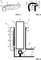
- Figs. 3 and 4 illustrate a third embodiment of an accessory 40, according to the invention. Again, elements that have the same functionality as in the first embodiment are designated with the same reference signs as in Fig. 1 .
- the fastening structure 42 is designed as a ring for attachment to the inlet end of the inhaler, more specifically, to the upper end 22 of the receiving portion of the inhaler housing.
- the accessory housing 41 forms an axial stop with the upper end face of the inhaler housing to define the correct axial position of the accessory 40 on the inhaler housing.
- the housing 41 of the accessory 40 according to the third embodiment has a plurality of openings, in particular, four openings, arranged along the circumference of the open end 22 of the receiving portion of the inhaler housing.
- all openings communicate pneumatically with a common duct 44, which in turn communicates pneumatically with the electronic sensor 45.
- all openings together form the pressure port 43 of the third embodiment.
- Each opening has a sufficiently small individual cross-sectional area that dust or drops of liquid cannot easily enter the duct 44.
- the openings together have a total cross-sectional area that gas exchange is possible between the inside and the outside of the duct 44 at a sufficiently high rate for ensuring proper operation of the electronic sensor 45.
- the electronic sensor 45 can be a differential pressure sensor or flow sensor, having two sensor ports 53, 54, the first sensor port being connected in a fluid-tight manner to the duct 44, while the second sensor port is in pneumatic communication with the environment via the reference port 46.
- Fig. 5 illustrates a fourth embodiment of an accessory 40, which is not part of the claimed invention, together with a correspondingly configured inhaler 10. Again, elements that have the same functionality as in the first embodiment are designated with the same reference signs as in Fig. 1 .
- the accessory 40 is attached to the outside of the inhaler housing 20 and can be easily removed from the inhaler.
- the circumferential wall 21 of the inhaler housing 20 is provided with a through-hole upstream from nozzle orifice 32, and the pressure port 43 is formed by the open end of a short pipe that extends into this through-hole to measure the flow rate of the air flow F1 without significantly disturbing the air flow.
- the accessory 40 or the inhaler housing 20 is provided with a flow-modifying structure adjacent to the pressure port 43 inside the inhaler housing 20 in order to be able to distinguish between inhalation and exhalation, as discussed above in conjunction with the second embodiment.
- the inhaler of the fourth embodiment may require adaptation to the intended use by providing the inhaler housing 20 with the through-hole for the pressure port 43.
- the electronic sensor can be of a different type than described above.
- the electronic sensor can be any other type of pressure sensor, for instance an absolute pressure sensor or a relative pressure sensor that is based on a different measurement principle than a flow measurement.
- the pressure sensor can be a barometric pressure sensor.
- the accessory can be fastened to the inhaler in a different manner than described. For instance, the accessory can be clamped to the inhaler body by two prong-like arms.
- the accessory of the present invention can also be used with other types of inhalers than the pMDI shown.
Landscapes
- Health & Medical Sciences (AREA)
- Engineering & Computer Science (AREA)
- Biomedical Technology (AREA)
- General Health & Medical Sciences (AREA)
- Public Health (AREA)
- Bioinformatics & Cheminformatics (AREA)
- Anesthesiology (AREA)
- Life Sciences & Earth Sciences (AREA)
- Veterinary Medicine (AREA)
- Animal Behavior & Ethology (AREA)
- Hematology (AREA)
- Pulmonology (AREA)
- Heart & Thoracic Surgery (AREA)
- Medical Informatics (AREA)
- Epidemiology (AREA)
- Primary Health Care (AREA)
- Business, Economics & Management (AREA)
- General Business, Economics & Management (AREA)
- Physics & Mathematics (AREA)
- Fluid Mechanics (AREA)
- General Physics & Mathematics (AREA)
- Chemical & Material Sciences (AREA)
- Medicinal Chemistry (AREA)
- Measurement Of The Respiration, Hearing Ability, Form, And Blood Characteristics Of Living Organisms (AREA)
Claims (14)
- Un accessoire (40) pour un inhalateur (10), l'inhalateur (10) ayant une entrée d'air pour l'entrée d'air dans l'inhalateur (10) et une sortie d'air pour communiquer avec la bouche d'un patient, de sorte que l'inhalation par un le patient à travers la sortie d'air provoque un flux d'air d'inhalation (F1) à travers l'inhalateur (10) de l'entrée d'air à la sortie d'air, l'inhalateur (10) définissant en outre une zone de mélange (33) entre l'entrée d'air et la sortie d'air pour mélanger le flux d'air (F1) avec un médicament, l'accessoire (40) comprenant:un boitier d'accessoire (41);un orifice de pression (43);un capteur électronique (45) pour déterminer un débit du flux d'air d'inhalation (F1), le capteur électronique (45) étant logé dans le boitier d'accessoire (41), le capteur électronique (45) étant en communication avec l'orifice de pression (43), le capteur électronique (45) étant sensible à un changement de pression au niveau de l'orifice de pression (43) provoqué par le flux d'air d'inhalation (F1); etune structure de fixation (42) pour fixer l'accessoire (40) à l'extérieur de l'inhalateur (10), la structure de fixation (42) étant configurée pour fixer l'accessoire (40) à un extérieur de l'inhalateur (10) de telle manière que l'orifice de pression (43) est disposé en amont de l'entrée d'air de l'inhalateur (10) et de la zone de mélange (33) par rapport au flux d'air d'inhalation (F1),caractérisé en ce que l'orifice de pression (43) est formé par une pluralité d'ouvertures dans le boîtier accessoire (41), les ouvertures étant distribuées de manière circonférentielle le long d'une circonférence de l'entrée d'air de l'inhalateur (10) lorsque l'accessoire (40) est fixé à l'inhalateur (10).
- L'accessoire (40) selon la revendication 1, étant configuré pour modifier le flux d'air d'inhalation (F1) adjacent à l'orifice de pression (43) de telle manière qu'un flux d'air inversé (F2) dû à l'expiration du patient à travers l'inhalateur (10) provoque un changement de pression au niveau de l'orifice de pression (43) avec un signe opposé par rapport au changement de pression provoqué par le flux d'air d'inhalation (F1) dû à l'inhalation, dans lequel la modification du flux d'air d'inhalation (F1) est engendrée par une structure modifiant le flux de l'accessoire causant une pression dynamique positive au niveau de l'orifice de pression (43) pour uniquement une des directions de flux du flux d'air d'inhalation (F1) et du flux d'air inversé (F2).
- L'accessoire selon la revendication 1 ou 2, dans lequel le boitier d'accessoire (41) définit une structure d'arrêt axiale configurée pour venir en butée avec une face d'extrémité proximale d'une paroi de boîtier (21) d'un boîtier (20) de l'inhalateur (10), lorsque l'accessoire (40) est fixé à l'inhalateur (10), et dans lequel une partie de la paroi du boitier d'accessoire (41) dans lequel l'orifice de pression (43) est disposé est adjacent à la structure d'arrêt.
- L'accessoire (40) selon l'une quelconque des revendications précédentes, dans lequel la structure de fixation (42) comprend un anneau configuré pour être agencé autour d'un boîtier d'inhalateur (20) de l'inhalateur (10).
- L'accessoire (40) selon l'une quelconque des revendications précédentes, dans lequel le capteur électronique est un capteur de pression absolue, un capteur de pression barométrique, un capteur de pression différentielle ou un capteur de flux.
- L'accessoire (40) selon l'une quelconque des revendications précédentes,dans lequel le capteur électronique (45) est un capteur de pression différentielle ou un capteur de flux, le capteur électronique ayant un premier et un second orifice de capteur (53, 54), le premier orifice de capteur (53) étant en communication avec l'orifice de pression (43),dans lequel l'accessoire (40) comprend un orifice de référence (46), le second orifice de capteur (54) étant en communication avec l'orifice de référence (46), etdans lequel l'orifice de référence (46) est agencé de telle sorte que le flux d'air d'inhalation (F1) ne provoque pas de changement de pression au niveau de l'orifice de référence (46) ou provoque un changement de pression de signe et / ou de grandeur différents au niveau de l'orifice de référence (46) qu'au niveau de l'orifice de pression (43) lorsque l'accessoire (40) est fixé à l'inhalateur (10).
- L'accessoire (40) selon l'une quelconque des revendications précédentes, comprenant en outre un circuits électronique (47) connecté au capteur électronique (45), le circuit électronique (47) étant opérables pour recevoir des signaux de capteur du capteur électronique (45) et pour dériver un signal de sortie basé sur les signaux du capteur.
- L'accessoire selon la revendication 7, dans lequel le circuit électronique (47) est configuré pour transmettre le signal de sortie via une liaison sans fil à un dispositif distant (60).
- Un système d'inhalation comprenant:un inhalateur (10) ayant une entrée d'air pour l'entrée d'air dans l'inhalateur (10) et une sortie d'air pour communiquer avec la bouche d'un patient, l'inhalateur (10) étant configuré de telle sorte que l'inhalation par un patient à travers la sortie d'air provoque un flux d'air d'inhalation (F1) à travers l'inhalateur (10) de l'entrée d'air à la sortie d'air, l'inhalateur (10) définissant en outre une zone de mélange entre l'entrée d'air et la sortie d'air pour mélanger le flux d'air avec un médicament,dans lequel le système d'inhalation comprend en outre un accessoire (40) selon l'une quelconque des revendications précédentes.
- Le système d'inhalation selon la revendication 9, dans lequel l'inhalateur (10) comprend en outre:un boîtier d'inhalateur (20); etun réservoir de médicament (11) logé dans le boîtier d'inhalateur (20), le réservoir de médicament (11) étant configuré pour libérer un médicament en aérosol dans un trajet de flux d'air entre l'entrée d'air et la sortie d'air,dans lequel la structure de fixation (42) de l'accessoire (40) est configurée pour fixer l'accessoire (40) au boîtier d'inhalateur (20).
- Le système d'inhalation de la revendication 9 ou 10, dans lequel l'orifice de pression (43) de l'accessoire est disposé dans une partie de la paroi du boitier d'accessoire (41) de l'accessoire qui est sensiblement cohérente avec la paroi de boitier de l'inhalateur du boitier d'inhalateur (20) lorsque l'accessoire (40) est fixé à l'inhalateur (10), la partie de la paroi du boitier d'accessoire (41) et la paroi de boitier du boitier d'inhalateur (20) délimitant un trajet de flux du flux d'air d'inhalation.
- Un procédé consistant de l'étape suivante:
fixer un accessoire selon l'une quelconque des revendications 1 à 8 à un inhalateur (10) ayant une entrée d'air pour l'entrée d'air dans l'inhalateur (10) et une sortie d'air pour communiquer avec la bouche d'un patient, l'inhalateur définissant une zone de mélange (33) entre l'entrée d'air et la sortie d'air pour mélanger un flux d'air à travers l'inhalateur de l'entrée d'air vers la sortie d'air avec un médicament; de sorte que:le capteur électronique (45) de l'accessoire (40) est configuré pour mesurer un paramètre de pression indicatif d'un changement de pression au niveau de l'orifice de pression (43) provoqué par l'écoulement d'air (F1); etun paramètre de débit qui est indicatif du débit à travers l'inhalateur (10) peut être déterminé sur la base du paramètre de pression. - Le procédé selon la revendication 12 dans lequel l'accessoire (40) comprend un circuit électronique (47) connecté au capteur électronique (45), et le circuit électronique (47) est configuré pour déterminer un paramètre de débit.
- Le procédé selon la revendication 13 dans lequel le circuit électronique (47) est configuré en outre pour :sur la base du paramètre de débit déterminé, générer un signal de sortie ettransmettre le signal de sortie généré à un dispositif distant (60) via une liaison sans fil;de sorte que le dispositif distant (60) peut être opéré pour recevoir le signal de sortie transmis.
Priority Applications (2)
| Application Number | Priority Date | Filing Date | Title |
|---|---|---|---|
| EP18207022.7A EP3653247B1 (fr) | 2018-11-19 | 2018-11-19 | Détermination d'un débit d'air à travers un inhalateur |
| US16/687,028 US20200155773A1 (en) | 2018-11-19 | 2019-11-18 | Determination of air flow rate through an inhaler |
Applications Claiming Priority (1)
| Application Number | Priority Date | Filing Date | Title |
|---|---|---|---|
| EP18207022.7A EP3653247B1 (fr) | 2018-11-19 | 2018-11-19 | Détermination d'un débit d'air à travers un inhalateur |
Publications (2)
| Publication Number | Publication Date |
|---|---|
| EP3653247A1 EP3653247A1 (fr) | 2020-05-20 |
| EP3653247B1 true EP3653247B1 (fr) | 2021-03-31 |
Family
ID=64362425
Family Applications (1)
| Application Number | Title | Priority Date | Filing Date |
|---|---|---|---|
| EP18207022.7A Active EP3653247B1 (fr) | 2018-11-19 | 2018-11-19 | Détermination d'un débit d'air à travers un inhalateur |
Country Status (2)
| Country | Link |
|---|---|
| US (1) | US20200155773A1 (fr) |
| EP (1) | EP3653247B1 (fr) |
Cited By (4)
| Publication number | Priority date | Publication date | Assignee | Title |
|---|---|---|---|---|
| US11497867B2 (en) | 2016-12-09 | 2022-11-15 | Trudell Medical International | Smart nebulizer |
| US11666801B2 (en) | 2018-01-04 | 2023-06-06 | Trudell Medical International | Smart oscillating positive expiratory pressure device |
| US11712175B2 (en) | 2019-08-27 | 2023-08-01 | Trudell Medical International | Smart oscillating positive expiratory pressure device with feedback indicia |
| US11839716B2 (en) | 2016-07-08 | 2023-12-12 | Trudell Medical International | Smart oscillating positive expiratory pressure device |
Families Citing this family (8)
| Publication number | Priority date | Publication date | Assignee | Title |
|---|---|---|---|---|
| IL291998B2 (en) * | 2019-11-18 | 2025-02-01 | Vectura Delivery Devices Ltd | Inhaler for use with a compliance monitor |
| MX2022007103A (es) | 2019-12-10 | 2022-09-02 | Trudell Medical Int | Contador de dosis integrado. |
| US11464923B2 (en) | 2020-06-19 | 2022-10-11 | Norton (Waterford) Limited | Inhaler system |
| US12233201B2 (en) | 2020-06-19 | 2025-02-25 | Norton (Waterford) Limited | Inhaler system |
| CN112156291B (zh) * | 2020-08-05 | 2022-12-13 | 湖南人文科技学院 | 口吸式雾化器 |
| DE102020214414A1 (de) | 2020-11-17 | 2022-05-19 | Robert Bosch Gesellschaft mit beschränkter Haftung | Unterstützungsvorrichtung zum Unterstützen eines Patienten während eines Anwendungsvorgangs einer Medikamentenabgabevorrichtung und Verfahren zum Betreiben einer Unterstützungsvorrichtung |
| CN116510139B (zh) * | 2023-04-04 | 2025-12-12 | 深圳雾芯科技有限公司 | 用于吸入器的测速装置及具有其的吸入器套装 |
| WO2025021887A1 (fr) | 2023-07-27 | 2025-01-30 | Chiesi Farmaceutici S.P.A. | Module électronique pour inhalateur doseur et ensemble inhalateur doseur comprenant le module électronique |
Family Cites Families (15)
| Publication number | Priority date | Publication date | Assignee | Title |
|---|---|---|---|---|
| US5392768A (en) * | 1991-03-05 | 1995-02-28 | Aradigm | Method and apparatus for releasing a controlled amount of aerosol medication over a selectable time interval |
| DE69424992T2 (de) * | 1994-02-14 | 2000-10-26 | Aradigm Corp., Hayward | Inhalationsübungsgerät |
| US5809997A (en) * | 1995-05-18 | 1998-09-22 | Medtrac Technologies, Inc. | Electronic medication chronolog device |
| GB9814717D0 (en) | 1998-02-23 | 1998-09-02 | Bespak Plc | Improvements in drug delivery devices |
| GB9911388D0 (en) * | 1999-05-18 | 1999-07-14 | Glaxo Group Ltd | Dispenser |
| WO2011157561A1 (fr) * | 2010-06-18 | 2011-12-22 | Boehringer Ingelheim International Gmbh | Inhalateur |
| GB201107103D0 (en) | 2011-04-27 | 2011-06-08 | Clement Clarke Int Ltd | Improvements in drug delivery inhaler devices |
| WO2015109259A1 (fr) * | 2014-01-16 | 2015-07-23 | Focusstart Respiratory Llc | Systèmes et procédés pour gérer une administration de médicament pulmonaire |
| MX379352B (es) * | 2014-08-28 | 2025-03-11 | Norton Waterford Ltd | Módulo de monitoreo de cumplimiento para un inhalador. |
| AU2015350319A1 (en) * | 2014-11-20 | 2017-06-15 | Cognita Labs, LLC | Method and apparatus to measure, aid and correct the use of inhalers |
| EP3032227B1 (fr) | 2014-12-08 | 2020-10-21 | Sensirion AG | Package de capteur de débit |
| MX2018012419A (es) * | 2016-04-12 | 2019-03-07 | Biocorp Production SA | Dispositivo accesorio de inhalador de dosis medida, sistema de mejora de la observancia y metodo para mejorar la observancia de uso en inhaladores de dosis medida. |
| JP2019516485A (ja) * | 2016-05-19 | 2019-06-20 | マンカインド コーポレイション | 吸入を検出および監視するための機器、システム、および方法 |
| ES2929335T3 (es) * | 2016-05-27 | 2022-11-28 | Proveris Scient Corporation | Dispositivos para el uso de dispositivos de medicamento |
| EP3338842A1 (fr) * | 2016-12-22 | 2018-06-27 | Bernhard Schulz | Nébuliseur pour l'inhalation à flux laminaire d'un aérosol |
-
2018
- 2018-11-19 EP EP18207022.7A patent/EP3653247B1/fr active Active
-
2019
- 2019-11-18 US US16/687,028 patent/US20200155773A1/en not_active Abandoned
Non-Patent Citations (1)
| Title |
|---|
| None * |
Cited By (8)
| Publication number | Priority date | Publication date | Assignee | Title |
|---|---|---|---|---|
| US11839716B2 (en) | 2016-07-08 | 2023-12-12 | Trudell Medical International | Smart oscillating positive expiratory pressure device |
| US12514997B2 (en) | 2016-07-08 | 2026-01-06 | Trudell Medical International Inc. | Smart oscillating positive expiratory pressure device |
| US11497867B2 (en) | 2016-12-09 | 2022-11-15 | Trudell Medical International | Smart nebulizer |
| US12465705B2 (en) | 2016-12-09 | 2025-11-11 | Trudell Medical International Inc. | Smart nebulizer |
| US11666801B2 (en) | 2018-01-04 | 2023-06-06 | Trudell Medical International | Smart oscillating positive expiratory pressure device |
| US11964185B2 (en) | 2018-01-04 | 2024-04-23 | Trudell Medical International | Smart oscillating positive expiratory pressure device |
| US12214252B2 (en) | 2018-01-04 | 2025-02-04 | Trudell Medical International Inc. | Smart oscillating positive expiratory pressure device |
| US11712175B2 (en) | 2019-08-27 | 2023-08-01 | Trudell Medical International | Smart oscillating positive expiratory pressure device with feedback indicia |
Also Published As
| Publication number | Publication date |
|---|---|
| EP3653247A1 (fr) | 2020-05-20 |
| US20200155773A1 (en) | 2020-05-21 |
Similar Documents
| Publication | Publication Date | Title |
|---|---|---|
| EP3653247B1 (fr) | Détermination d'un débit d'air à travers un inhalateur | |
| US11944425B2 (en) | Compliance monitoring module for an inhaler | |
| JP6931108B2 (ja) | 呼吸作動式の吸入器用のコンプライアンス監視モジュール | |
| US6192876B1 (en) | Inhalation apparatus and method | |
| AU741727B2 (en) | Inhalation apparatus and method | |
| US9155846B2 (en) | Dosage inhaler | |
| CN101687086B (zh) | 具有气体标识装置的患者通气系统 | |
| EP1058570B1 (fr) | Appareil de surveillance d'un patient | |
| CN106687034B (zh) | 具有微型压力传感器激活的潮式干粉吸入器 | |
| AU2017219695B2 (en) | Device with flow rate indicator | |
| GB2547549A (en) | Device with flow rate indicator | |
| JP2021035441A (ja) | 呼吸流量測定装置 | |
| HK1235653A1 (en) | Tidal dry powder inhaler with miniature pressure sensor activation | |
| HK1236079B (en) | Compliance monitoring module for an inhaler |
Legal Events
| Date | Code | Title | Description |
|---|---|---|---|
| PUAI | Public reference made under article 153(3) epc to a published international application that has entered the european phase |
Free format text: ORIGINAL CODE: 0009012 |
|
| STAA | Information on the status of an ep patent application or granted ep patent |
Free format text: STATUS: THE APPLICATION HAS BEEN PUBLISHED |
|
| AK | Designated contracting states |
Kind code of ref document: A1 Designated state(s): AL AT BE BG CH CY CZ DE DK EE ES FI FR GB GR HR HU IE IS IT LI LT LU LV MC MK MT NL NO PL PT RO RS SE SI SK SM TR |
|
| AX | Request for extension of the european patent |
Extension state: BA ME |
|
| STAA | Information on the status of an ep patent application or granted ep patent |
Free format text: STATUS: REQUEST FOR EXAMINATION WAS MADE |
|
| 17P | Request for examination filed |
Effective date: 20200609 |
|
| RBV | Designated contracting states (corrected) |
Designated state(s): AL AT BE BG CH CY CZ DE DK EE ES FI FR GB GR HR HU IE IS IT LI LT LU LV MC MK MT NL NO PL PT RO RS SE SI SK SM TR |
|
| GRAP | Despatch of communication of intention to grant a patent |
Free format text: ORIGINAL CODE: EPIDOSNIGR1 |
|
| STAA | Information on the status of an ep patent application or granted ep patent |
Free format text: STATUS: GRANT OF PATENT IS INTENDED |
|
| RIC1 | Information provided on ipc code assigned before grant |
Ipc: A61B 5/087 20060101ALN20200922BHEP Ipc: A61M 16/08 20060101ALN20200922BHEP Ipc: A61B 5/00 20060101ALN20200922BHEP Ipc: G16H 40/67 20180101ALI20200922BHEP Ipc: G16H 20/13 20180101ALI20200922BHEP Ipc: G16H 40/63 20180101ALI20200922BHEP Ipc: A61M 15/00 20060101AFI20200922BHEP Ipc: A61M 16/00 20060101ALN20200922BHEP |
|
| RIC1 | Information provided on ipc code assigned before grant |
Ipc: A61B 5/00 20060101ALN20201001BHEP Ipc: G16H 40/67 20180101ALI20201001BHEP Ipc: G16H 40/63 20180101ALI20201001BHEP Ipc: G01F 15/06 20060101ALI20201001BHEP Ipc: G16H 20/13 20180101ALI20201001BHEP Ipc: G01F 1/34 20060101ALI20201001BHEP Ipc: A61M 16/08 20060101ALN20201001BHEP Ipc: A61M 16/00 20060101ALN20201001BHEP Ipc: A61B 5/087 20060101ALN20201001BHEP Ipc: G01F 15/14 20060101ALN20201001BHEP Ipc: A61M 15/00 20060101AFI20201001BHEP |
|
| INTG | Intention to grant announced |
Effective date: 20201016 |
|
| GRAS | Grant fee paid |
Free format text: ORIGINAL CODE: EPIDOSNIGR3 |
|
| GRAA | (expected) grant |
Free format text: ORIGINAL CODE: 0009210 |
|
| STAA | Information on the status of an ep patent application or granted ep patent |
Free format text: STATUS: THE PATENT HAS BEEN GRANTED |
|
| AK | Designated contracting states |
Kind code of ref document: B1 Designated state(s): AL AT BE BG CH CY CZ DE DK EE ES FI FR GB GR HR HU IE IS IT LI LT LU LV MC MK MT NL NO PL PT RO RS SE SI SK SM TR |
|
| REG | Reference to a national code |
Ref country code: GB Ref legal event code: FG4D Ref country code: CH Ref legal event code: EP |
|
| REG | Reference to a national code |
Ref country code: DE Ref legal event code: R096 Ref document number: 602018014667 Country of ref document: DE Ref country code: AT Ref legal event code: REF Ref document number: 1376227 Country of ref document: AT Kind code of ref document: T Effective date: 20210415 |
|
| REG | Reference to a national code |
Ref country code: IE Ref legal event code: FG4D |
|
| REG | Reference to a national code |
Ref country code: LT Ref legal event code: MG9D |
|
| PG25 | Lapsed in a contracting state [announced via postgrant information from national office to epo] |
Ref country code: NO Free format text: LAPSE BECAUSE OF FAILURE TO SUBMIT A TRANSLATION OF THE DESCRIPTION OR TO PAY THE FEE WITHIN THE PRESCRIBED TIME-LIMIT Effective date: 20210630 Ref country code: BG Free format text: LAPSE BECAUSE OF FAILURE TO SUBMIT A TRANSLATION OF THE DESCRIPTION OR TO PAY THE FEE WITHIN THE PRESCRIBED TIME-LIMIT Effective date: 20210630 Ref country code: HR Free format text: LAPSE BECAUSE OF FAILURE TO SUBMIT A TRANSLATION OF THE DESCRIPTION OR TO PAY THE FEE WITHIN THE PRESCRIBED TIME-LIMIT Effective date: 20210331 Ref country code: FI Free format text: LAPSE BECAUSE OF FAILURE TO SUBMIT A TRANSLATION OF THE DESCRIPTION OR TO PAY THE FEE WITHIN THE PRESCRIBED TIME-LIMIT Effective date: 20210331 |
|
| PG25 | Lapsed in a contracting state [announced via postgrant information from national office to epo] |
Ref country code: SE Free format text: LAPSE BECAUSE OF FAILURE TO SUBMIT A TRANSLATION OF THE DESCRIPTION OR TO PAY THE FEE WITHIN THE PRESCRIBED TIME-LIMIT Effective date: 20210331 Ref country code: LV Free format text: LAPSE BECAUSE OF FAILURE TO SUBMIT A TRANSLATION OF THE DESCRIPTION OR TO PAY THE FEE WITHIN THE PRESCRIBED TIME-LIMIT Effective date: 20210331 Ref country code: RS Free format text: LAPSE BECAUSE OF FAILURE TO SUBMIT A TRANSLATION OF THE DESCRIPTION OR TO PAY THE FEE WITHIN THE PRESCRIBED TIME-LIMIT Effective date: 20210331 |
|
| REG | Reference to a national code |
Ref country code: NL Ref legal event code: MP Effective date: 20210331 |
|
| REG | Reference to a national code |
Ref country code: AT Ref legal event code: MK05 Ref document number: 1376227 Country of ref document: AT Kind code of ref document: T Effective date: 20210331 |
|
| PG25 | Lapsed in a contracting state [announced via postgrant information from national office to epo] |
Ref country code: CZ Free format text: LAPSE BECAUSE OF FAILURE TO SUBMIT A TRANSLATION OF THE DESCRIPTION OR TO PAY THE FEE WITHIN THE PRESCRIBED TIME-LIMIT Effective date: 20210331 Ref country code: EE Free format text: LAPSE BECAUSE OF FAILURE TO SUBMIT A TRANSLATION OF THE DESCRIPTION OR TO PAY THE FEE WITHIN THE PRESCRIBED TIME-LIMIT Effective date: 20210331 Ref country code: LT Free format text: LAPSE BECAUSE OF FAILURE TO SUBMIT A TRANSLATION OF THE DESCRIPTION OR TO PAY THE FEE WITHIN THE PRESCRIBED TIME-LIMIT Effective date: 20210331 Ref country code: SM Free format text: LAPSE BECAUSE OF FAILURE TO SUBMIT A TRANSLATION OF THE DESCRIPTION OR TO PAY THE FEE WITHIN THE PRESCRIBED TIME-LIMIT Effective date: 20210331 Ref country code: NL Free format text: LAPSE BECAUSE OF FAILURE TO SUBMIT A TRANSLATION OF THE DESCRIPTION OR TO PAY THE FEE WITHIN THE PRESCRIBED TIME-LIMIT Effective date: 20210331 Ref country code: AT Free format text: LAPSE BECAUSE OF FAILURE TO SUBMIT A TRANSLATION OF THE DESCRIPTION OR TO PAY THE FEE WITHIN THE PRESCRIBED TIME-LIMIT Effective date: 20210331 |
|
| PG25 | Lapsed in a contracting state [announced via postgrant information from national office to epo] |
Ref country code: IS Free format text: LAPSE BECAUSE OF FAILURE TO SUBMIT A TRANSLATION OF THE DESCRIPTION OR TO PAY THE FEE WITHIN THE PRESCRIBED TIME-LIMIT Effective date: 20210731 Ref country code: PL Free format text: LAPSE BECAUSE OF FAILURE TO SUBMIT A TRANSLATION OF THE DESCRIPTION OR TO PAY THE FEE WITHIN THE PRESCRIBED TIME-LIMIT Effective date: 20210331 Ref country code: PT Free format text: LAPSE BECAUSE OF FAILURE TO SUBMIT A TRANSLATION OF THE DESCRIPTION OR TO PAY THE FEE WITHIN THE PRESCRIBED TIME-LIMIT Effective date: 20210802 Ref country code: RO Free format text: LAPSE BECAUSE OF FAILURE TO SUBMIT A TRANSLATION OF THE DESCRIPTION OR TO PAY THE FEE WITHIN THE PRESCRIBED TIME-LIMIT Effective date: 20210331 Ref country code: SK Free format text: LAPSE BECAUSE OF FAILURE TO SUBMIT A TRANSLATION OF THE DESCRIPTION OR TO PAY THE FEE WITHIN THE PRESCRIBED TIME-LIMIT Effective date: 20210331 |
|
| REG | Reference to a national code |
Ref country code: DE Ref legal event code: R097 Ref document number: 602018014667 Country of ref document: DE |
|
| PG25 | Lapsed in a contracting state [announced via postgrant information from national office to epo] |
Ref country code: ES Free format text: LAPSE BECAUSE OF FAILURE TO SUBMIT A TRANSLATION OF THE DESCRIPTION OR TO PAY THE FEE WITHIN THE PRESCRIBED TIME-LIMIT Effective date: 20210331 Ref country code: DK Free format text: LAPSE BECAUSE OF FAILURE TO SUBMIT A TRANSLATION OF THE DESCRIPTION OR TO PAY THE FEE WITHIN THE PRESCRIBED TIME-LIMIT Effective date: 20210331 Ref country code: AL Free format text: LAPSE BECAUSE OF FAILURE TO SUBMIT A TRANSLATION OF THE DESCRIPTION OR TO PAY THE FEE WITHIN THE PRESCRIBED TIME-LIMIT Effective date: 20210331 |
|
| PLBE | No opposition filed within time limit |
Free format text: ORIGINAL CODE: 0009261 |
|
| STAA | Information on the status of an ep patent application or granted ep patent |
Free format text: STATUS: NO OPPOSITION FILED WITHIN TIME LIMIT |
|
| 26N | No opposition filed |
Effective date: 20220104 |
|
| PG25 | Lapsed in a contracting state [announced via postgrant information from national office to epo] |
Ref country code: IS Free format text: LAPSE BECAUSE OF FAILURE TO SUBMIT A TRANSLATION OF THE DESCRIPTION OR TO PAY THE FEE WITHIN THE PRESCRIBED TIME-LIMIT Effective date: 20210731 |
|
| PG25 | Lapsed in a contracting state [announced via postgrant information from national office to epo] |
Ref country code: MC Free format text: LAPSE BECAUSE OF FAILURE TO SUBMIT A TRANSLATION OF THE DESCRIPTION OR TO PAY THE FEE WITHIN THE PRESCRIBED TIME-LIMIT Effective date: 20210331 |
|
| PG25 | Lapsed in a contracting state [announced via postgrant information from national office to epo] |
Ref country code: LU Free format text: LAPSE BECAUSE OF NON-PAYMENT OF DUE FEES Effective date: 20211119 Ref country code: IT Free format text: LAPSE BECAUSE OF FAILURE TO SUBMIT A TRANSLATION OF THE DESCRIPTION OR TO PAY THE FEE WITHIN THE PRESCRIBED TIME-LIMIT Effective date: 20210331 Ref country code: BE Free format text: LAPSE BECAUSE OF NON-PAYMENT OF DUE FEES Effective date: 20211130 |
|
| REG | Reference to a national code |
Ref country code: BE Ref legal event code: MM Effective date: 20211130 |
|
| PG25 | Lapsed in a contracting state [announced via postgrant information from national office to epo] |
Ref country code: IE Free format text: LAPSE BECAUSE OF NON-PAYMENT OF DUE FEES Effective date: 20211119 |
|
| PG25 | Lapsed in a contracting state [announced via postgrant information from national office to epo] |
Ref country code: FR Free format text: LAPSE BECAUSE OF NON-PAYMENT OF DUE FEES Effective date: 20211130 |
|
| PG25 | Lapsed in a contracting state [announced via postgrant information from national office to epo] |
Ref country code: CY Free format text: LAPSE BECAUSE OF FAILURE TO SUBMIT A TRANSLATION OF THE DESCRIPTION OR TO PAY THE FEE WITHIN THE PRESCRIBED TIME-LIMIT Effective date: 20210331 |
|
| P01 | Opt-out of the competence of the unified patent court (upc) registered |
Effective date: 20230602 |
|
| PG25 | Lapsed in a contracting state [announced via postgrant information from national office to epo] |
Ref country code: HU Free format text: LAPSE BECAUSE OF FAILURE TO SUBMIT A TRANSLATION OF THE DESCRIPTION OR TO PAY THE FEE WITHIN THE PRESCRIBED TIME-LIMIT; INVALID AB INITIO Effective date: 20181119 Ref country code: GR Free format text: LAPSE BECAUSE OF FAILURE TO SUBMIT A TRANSLATION OF THE DESCRIPTION OR TO PAY THE FEE WITHIN THE PRESCRIBED TIME-LIMIT Effective date: 20210331 |
|
| PG25 | Lapsed in a contracting state [announced via postgrant information from national office to epo] |
Ref country code: MK Free format text: LAPSE BECAUSE OF FAILURE TO SUBMIT A TRANSLATION OF THE DESCRIPTION OR TO PAY THE FEE WITHIN THE PRESCRIBED TIME-LIMIT Effective date: 20210331 |
|
| PG25 | Lapsed in a contracting state [announced via postgrant information from national office to epo] |
Ref country code: MT Free format text: LAPSE BECAUSE OF FAILURE TO SUBMIT A TRANSLATION OF THE DESCRIPTION OR TO PAY THE FEE WITHIN THE PRESCRIBED TIME-LIMIT Effective date: 20210331 |
|
| REG | Reference to a national code |
Ref country code: CH Ref legal event code: U11 Free format text: ST27 STATUS EVENT CODE: U-0-0-U10-U11 (AS PROVIDED BY THE NATIONAL OFFICE) Effective date: 20251201 |
|
| PG25 | Lapsed in a contracting state [announced via postgrant information from national office to epo] |
Ref country code: TR Free format text: LAPSE BECAUSE OF FAILURE TO SUBMIT A TRANSLATION OF THE DESCRIPTION OR TO PAY THE FEE WITHIN THE PRESCRIBED TIME-LIMIT Effective date: 20210331 |
|
| PGFP | Annual fee paid to national office [announced via postgrant information from national office to epo] |
Ref country code: DE Payment date: 20251118 Year of fee payment: 8 |
|
| PGFP | Annual fee paid to national office [announced via postgrant information from national office to epo] |
Ref country code: GB Payment date: 20251120 Year of fee payment: 8 |
|
| PGFP | Annual fee paid to national office [announced via postgrant information from national office to epo] |
Ref country code: CH Payment date: 20251201 Year of fee payment: 8 |