EP3653372A1 - Verfahren zur herstellung eines mehrrippigen flügelkastens aus verbundstoffmaterial mit integrierten versteiften platten und kommunikationsschächten - Google Patents
Verfahren zur herstellung eines mehrrippigen flügelkastens aus verbundstoffmaterial mit integrierten versteiften platten und kommunikationsschächten Download PDFInfo
- Publication number
- EP3653372A1 EP3653372A1 EP19208436.6A EP19208436A EP3653372A1 EP 3653372 A1 EP3653372 A1 EP 3653372A1 EP 19208436 A EP19208436 A EP 19208436A EP 3653372 A1 EP3653372 A1 EP 3653372A1
- Authority
- EP
- European Patent Office
- Prior art keywords
- panel
- rib
- ribs
- wing
- inserts
- Prior art date
- Legal status (The legal status is an assumption and is not a legal conclusion. Google has not performed a legal analysis and makes no representation as to the accuracy of the status listed.)
- Granted
Links
Images


Classifications
-
- B—PERFORMING OPERATIONS; TRANSPORTING
- B32—LAYERED PRODUCTS
- B32B—LAYERED PRODUCTS, i.e. PRODUCTS BUILT-UP OF STRATA OF FLAT OR NON-FLAT, e.g. CELLULAR OR HONEYCOMB, FORM
- B32B37/00—Methods or apparatus for laminating, e.g. by curing or by ultrasonic bonding
- B32B37/0076—Methods or apparatus for laminating, e.g. by curing or by ultrasonic bonding characterised in that the layers are not bonded on the totality of their surfaces
-
- B—PERFORMING OPERATIONS; TRANSPORTING
- B29—WORKING OF PLASTICS; WORKING OF SUBSTANCES IN A PLASTIC STATE IN GENERAL
- B29D—PRODUCING PARTICULAR ARTICLES FROM PLASTICS OR FROM SUBSTANCES IN A PLASTIC STATE
- B29D99/00—Subject matter not provided for in other groups of this subclass
- B29D99/001—Producing wall or panel-like structures, e.g. for hulls, fuselages, or buildings
- B29D99/0014—Producing wall or panel-like structures, e.g. for hulls, fuselages, or buildings provided with ridges or ribs, e.g. joined ribs
-
- B—PERFORMING OPERATIONS; TRANSPORTING
- B32—LAYERED PRODUCTS
- B32B—LAYERED PRODUCTS, i.e. PRODUCTS BUILT-UP OF STRATA OF FLAT OR NON-FLAT, e.g. CELLULAR OR HONEYCOMB, FORM
- B32B3/00—Layered products comprising a layer with external or internal discontinuities or unevennesses, or a layer of non-planar shape; Layered products comprising a layer having particular features of form
- B32B3/02—Layered products comprising a layer with external or internal discontinuities or unevennesses, or a layer of non-planar shape; Layered products comprising a layer having particular features of form characterised by features of form at particular places, e.g. in edge regions
- B32B3/08—Layered products comprising a layer with external or internal discontinuities or unevennesses, or a layer of non-planar shape; Layered products comprising a layer having particular features of form characterised by features of form at particular places, e.g. in edge regions characterised by added members at particular parts
- B32B3/085—Layered products comprising a layer with external or internal discontinuities or unevennesses, or a layer of non-planar shape; Layered products comprising a layer having particular features of form characterised by features of form at particular places, e.g. in edge regions characterised by added members at particular parts spaced apart pieces on the surface of a layer
-
- B—PERFORMING OPERATIONS; TRANSPORTING
- B32—LAYERED PRODUCTS
- B32B—LAYERED PRODUCTS, i.e. PRODUCTS BUILT-UP OF STRATA OF FLAT OR NON-FLAT, e.g. CELLULAR OR HONEYCOMB, FORM
- B32B37/00—Methods or apparatus for laminating, e.g. by curing or by ultrasonic bonding
- B32B37/10—Methods or apparatus for laminating, e.g. by curing or by ultrasonic bonding characterised by the pressing technique, e.g. using action of vacuum or fluid pressure
-
- B—PERFORMING OPERATIONS; TRANSPORTING
- B32—LAYERED PRODUCTS
- B32B—LAYERED PRODUCTS, i.e. PRODUCTS BUILT-UP OF STRATA OF FLAT OR NON-FLAT, e.g. CELLULAR OR HONEYCOMB, FORM
- B32B37/00—Methods or apparatus for laminating, e.g. by curing or by ultrasonic bonding
- B32B37/12—Methods or apparatus for laminating, e.g. by curing or by ultrasonic bonding characterised by using adhesives
-
- B—PERFORMING OPERATIONS; TRANSPORTING
- B32—LAYERED PRODUCTS
- B32B—LAYERED PRODUCTS, i.e. PRODUCTS BUILT-UP OF STRATA OF FLAT OR NON-FLAT, e.g. CELLULAR OR HONEYCOMB, FORM
- B32B7/00—Layered products characterised by the relation between layers; Layered products characterised by the relative orientation of features between layers, or by the relative values of a measurable parameter between layers, i.e. products comprising layers having different physical, chemical or physicochemical properties; Layered products characterised by the interconnection of layers
- B32B7/04—Interconnection of layers
- B32B7/12—Interconnection of layers using interposed adhesives or interposed materials with bonding properties
-
- B—PERFORMING OPERATIONS; TRANSPORTING
- B64—AIRCRAFT; AVIATION; COSMONAUTICS
- B64C—AEROPLANES; HELICOPTERS
- B64C1/00—Fuselages; Constructional features common to fuselages, wings, stabilising surfaces or the like
-
- B—PERFORMING OPERATIONS; TRANSPORTING
- B64—AIRCRAFT; AVIATION; COSMONAUTICS
- B64C—AEROPLANES; HELICOPTERS
- B64C3/00—Wings
- B64C3/18—Spars; Ribs; Stringers
- B64C3/182—Stringers, longerons
-
- B—PERFORMING OPERATIONS; TRANSPORTING
- B64—AIRCRAFT; AVIATION; COSMONAUTICS
- B64C—AEROPLANES; HELICOPTERS
- B64C3/00—Wings
- B64C3/18—Spars; Ribs; Stringers
- B64C3/187—Ribs
-
- B—PERFORMING OPERATIONS; TRANSPORTING
- B64—AIRCRAFT; AVIATION; COSMONAUTICS
- B64C—AEROPLANES; HELICOPTERS
- B64C3/00—Wings
- B64C3/26—Construction, shape, or attachment of separate skins, e.g. panels
-
- B—PERFORMING OPERATIONS; TRANSPORTING
- B64—AIRCRAFT; AVIATION; COSMONAUTICS
- B64F—GROUND OR AIRCRAFT-CARRIER-DECK INSTALLATIONS SPECIALLY ADAPTED FOR USE IN CONNECTION WITH AIRCRAFT; DESIGNING, MANUFACTURING, ASSEMBLING, CLEANING, MAINTAINING OR REPAIRING AIRCRAFT, NOT OTHERWISE PROVIDED FOR; HANDLING, TRANSPORTING, TESTING OR INSPECTING AIRCRAFT COMPONENTS, NOT OTHERWISE PROVIDED FOR
- B64F5/00—Designing, manufacturing, assembling, cleaning, maintaining or repairing aircraft, not otherwise provided for; Handling, transporting, testing or inspecting aircraft components, not otherwise provided for
- B64F5/10—Manufacturing or assembling aircraft, e.g. jigs therefor
-
- B—PERFORMING OPERATIONS; TRANSPORTING
- B29—WORKING OF PLASTICS; WORKING OF SUBSTANCES IN A PLASTIC STATE IN GENERAL
- B29L—INDEXING SCHEME ASSOCIATED WITH SUBCLASS B29C, RELATING TO PARTICULAR ARTICLES
- B29L2031/00—Other particular articles
- B29L2031/30—Vehicles, e.g. ships or aircraft, or body parts thereof
- B29L2031/3076—Aircrafts
- B29L2031/3085—Wings
-
- B—PERFORMING OPERATIONS; TRANSPORTING
- B32—LAYERED PRODUCTS
- B32B—LAYERED PRODUCTS, i.e. PRODUCTS BUILT-UP OF STRATA OF FLAT OR NON-FLAT, e.g. CELLULAR OR HONEYCOMB, FORM
- B32B2260/00—Layered product comprising an impregnated, embedded, or bonded layer wherein the layer comprises an impregnation, embedding, or binder material
- B32B2260/02—Composition of the impregnated, bonded or embedded layer
- B32B2260/021—Fibrous or filamentary layer
-
- B—PERFORMING OPERATIONS; TRANSPORTING
- B32—LAYERED PRODUCTS
- B32B—LAYERED PRODUCTS, i.e. PRODUCTS BUILT-UP OF STRATA OF FLAT OR NON-FLAT, e.g. CELLULAR OR HONEYCOMB, FORM
- B32B2260/00—Layered product comprising an impregnated, embedded, or bonded layer wherein the layer comprises an impregnation, embedding, or binder material
- B32B2260/04—Impregnation, embedding, or binder material
- B32B2260/046—Synthetic resin
-
- B—PERFORMING OPERATIONS; TRANSPORTING
- B32—LAYERED PRODUCTS
- B32B—LAYERED PRODUCTS, i.e. PRODUCTS BUILT-UP OF STRATA OF FLAT OR NON-FLAT, e.g. CELLULAR OR HONEYCOMB, FORM
- B32B2262/00—Composition or structural features of fibres which form a fibrous or filamentary layer or are present as additives
- B32B2262/10—Inorganic fibres
- B32B2262/101—Glass fibres
-
- B—PERFORMING OPERATIONS; TRANSPORTING
- B32—LAYERED PRODUCTS
- B32B—LAYERED PRODUCTS, i.e. PRODUCTS BUILT-UP OF STRATA OF FLAT OR NON-FLAT, e.g. CELLULAR OR HONEYCOMB, FORM
- B32B2262/00—Composition or structural features of fibres which form a fibrous or filamentary layer or are present as additives
- B32B2262/10—Inorganic fibres
- B32B2262/106—Carbon fibres, e.g. graphite fibres
-
- B—PERFORMING OPERATIONS; TRANSPORTING
- B32—LAYERED PRODUCTS
- B32B—LAYERED PRODUCTS, i.e. PRODUCTS BUILT-UP OF STRATA OF FLAT OR NON-FLAT, e.g. CELLULAR OR HONEYCOMB, FORM
- B32B2605/00—Vehicles
- B32B2605/18—Aircraft
-
- B—PERFORMING OPERATIONS; TRANSPORTING
- B64—AIRCRAFT; AVIATION; COSMONAUTICS
- B64C—AEROPLANES; HELICOPTERS
- B64C1/00—Fuselages; Constructional features common to fuselages, wings, stabilising surfaces or the like
- B64C2001/0054—Fuselage structures substantially made from particular materials
- B64C2001/0072—Fuselage structures substantially made from particular materials from composite materials
-
- B—PERFORMING OPERATIONS; TRANSPORTING
- B64—AIRCRAFT; AVIATION; COSMONAUTICS
- B64C—AEROPLANES; HELICOPTERS
- B64C3/00—Wings
- B64C3/18—Spars; Ribs; Stringers
- B64C3/185—Spars
-
- B—PERFORMING OPERATIONS; TRANSPORTING
- B64—AIRCRAFT; AVIATION; COSMONAUTICS
- B64C—AEROPLANES; HELICOPTERS
- B64C3/00—Wings
- B64C3/34—Tanks constructed integrally with wings, e.g. for fuel or water
Definitions
- the present invention relates in general to a method for manufacturing a structural part for aircraft.
- the invention relates to a method for manufacturing a multi-ribbed wing-box of composite material with integrated stiffened panels and communicating bays, that may be used in particular as a structural wing-box in a so called 'wet wing', that is a wing used also as a fuel tank, or in a vertical or horizontal empennage.
- the configuration currently adopted for aeronautical boxes - for wings or empennages of fixed-wing aircraft - consists of a set of different primary structural components, such as, typically, two stiffened panels with longitudinal stringers, two longitudinal spars, a certain number of transverse ribs, angular elements and conventional mechanical fastening elements.
- the so-called build-up configuration also entails significant drawbacks in the weight of the structure, which are badly tolerated in aeronautical applications, especially due to the increase in the operating cost of the aircraft, i.e. in fuel consumption.
- the weight increase for these assemblies is essentially due to the unavoidable presence of holes in the coupling areas between the various elements. Indeed, the holes, being a localized weakening of the component, require a thickening of the areas concerned, in order to safely withstand the design load.
- the weight of the fastening members also has a negative effect, since it is greater than the weight of the portion of material removed.
- wing boxes with highly curved aerodynamic profiles and/or with inner thickening or stiffening elements in the transverse direction (i.e., that extend in the direction of the length of the wing profile), or with the stringers interrupted in the longitudinal direction (i.e., perpendicular to the direction of the length of the wing profile) of the wing box, nor make a wing-box for a "wet wing", that is a wing-box provided with openings between adjacent bays to allow passage of fuel between them.
- the object of the present invention is to provide a method for manufacturing a wing-box for aircraft that overcomes the drawbacks and limitations of applicability of the known prior art, and allows manufacturing of a multi-ribbed wing-box of composite material suitable for a so called "wet wing", that is a wing-box whose bays are used as fuel tanks and wherein two adjacent bays are in fluid communication, without thus causing structural and quality defects like local thinning or resin accumulation at the communication openings between the bays.
- the invention is based on the idea of providing a method for manufacturing a wing-box for aircraft wherein the wing-box comprises a first panel, stiffened with a plurality of longitudinal stiffening stringers, and a plurality of ribs, arranged transversally, which are subjected jointly to a single curing process, wherein a plurality of support inserts is arranged in openings of each rib and in contact with respective caul plates to ensure the stability of the openings during the curing process. It is also possible to use a plurality of tools, that is of auxiliary tools, to ensure precise relative positioning of the components, each of said tools comprising, for example, a central removable part, which allows the removal of the tools even when the main body is fully assembled.
- a pair of spars may be mechanically assembled to the wing-box, in a known-per-se manner, with external closure on the long sides of the wing box.
- the first panel is supplied already polymerized, and the plurality of ribs is assembled to it by means of a co-bonding process, i.e. a ply of adhesive material is placed between the first panel and the ribs before curing.
- a co-bonding process i.e. a ply of adhesive material is placed between the first panel and the ribs before curing.
- the support inserts are made in a plastic material resistant to the specific pressure and temperature cycle of the curing process according, for example thermoplastic resin or pre-cured silicon rubber.
- the term 'longitudinal' indicates a direction substantially coincident or parallel with that of the main extension of the wing or of the empennage
- the term 'transverse' indicates a direction substantially perpendicular thereto, identifiable, in general, with a direction substantially coincident or parallel with that of a wing or empennage profile.
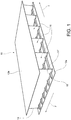
- a wing-box for aircraft as a whole is indicated with 10.
- the wing-box 10 comprises a first panel 12a and a plurality of ribs 14 that separate different bays 11 from each other.
- the wing-box may be completed with a second panel 12b, placed on top of the bays 11 to close them, and that may be mechanically assembled in a known-per-se manner at the end of the process, or be connected by means of a curing process or of a "co-bonding" process by means of a supplementary adhesive ply.
- the first panel 12a, the second panel 12b and the ribs 14 are made of composite material.
- the composite material comprises a matrix in thermoset resin or bismaleimide and/or a carbon and/or glass fibre reinforcement.
- the first panel 12a and the second panel 12b may be made in a similar way.
- first panel 12a for the sake of brevity, only the first panel 12a will be described, it being understood that the second panel 12b is generally made up of elements similar or identical to those of the first panel 12a, obtained by means of similar manufacturing processes.
- the first panel 12a comprises a skin 16 and a plurality of reinforcement stringers 18.
- the skin 16 comprises a sequence of plies of composite material, preferably of an epoxy resin matrix composite material with long carbon fibre reinforcement.
- the skin 16 may be obtained, for example, by means of lamination by hand or with automated systems according to the guidelines defined by the design of the component, or by means any other known process for laminating layers of composite material.
- vacuum bag compaction with or without heat application may be carried out in a manner known per se.
- the stringers 18 may have a closed cross-section of the omega type, trapezoidal type, or according to other geometries. Preferably, the stringers 18 have an omega-type cross-section.
- the stringers 18 may be obtained by any known procedure for processing composite materials.
- the stringers 18 may initially be flat-laminated, similarly to the skin 16, and then cut with a clean profile along an edge thereof, and subjected to a forming process, in accordance with different operating methods according to the known art.
- the stringers 18 may be formed on a male mould with membrane and vacuum application, or on a female mould with moulding, with or without heat application, etc.
- the stringers 18 may be laminated directly onto a mould, one ply at a time.
- the fresh, i.e., as of yet non-polymerized, stringers 18 may then be precisely positioned on the skin 16 by the use of auxiliary tools to support the stringers 18, and tilting systems coordinated with a lamination surface (not shown, but known per se) of the skin 16.
- elongated stabilization inserts 17 preferably made of solid cross-section silicone rubber, may be positioned in the space defined between each stringer 18 and the skin 16.
- the elongated stabilization inserts 17 placed in this space act as a support, whereon, during the process of polymerization in autoclave, the plies of composite material of each stringer 18 are consolidated, acquiring the final design shape.
- the advantage of the elongated stabilization inserts 17 is that they are flexible enough to adapt to any ramps and steps that may be envisaged on the skin 16 underneath the stringers 18.
- the elongated stabilization inserts 17 are able to tolerate the high temperature and pressure levels expected in the autoclave for the curing process (generally, about 180°C and 6 bar), without deformation and degradation, avoiding geometric defects to the stringers 18.
- the elongated stabilization inserts 17 are made with a silicone rubber compound that ensures the absence of contamination of the matrix of the composite material of the first or second panel 12a or 12b, and their thermal expansion must be controlled to ensure compliance with the geometric requirements and the proper compaction of each stringer 18 after the curing process.
- the elongated stabilization inserts 17 are made of a rubber of the group of basic VMQ elastomers (i.e., vinyl-methyl-polysiloxane, group Q, according to the ISO 1629 standard) having, for example, a hardness of about 70 shore A, a density of about 1.2 g/cm3, and a thermal expansion coefficient of about 250 ⁇ m/m°C.
- Other known methods for obtaining stringers 18 made of composite material according to the invention comprise, for example, the use of inflatable tubular bags.
- a caul plate 23 is typically placed made of carbon fibre or metal, sufficiently flexible, for example consisting of two consecutive layers of composite material, or aluminium layers of 0.5-1 mm. Said caul plate 23 ensures that the shape of the stringers 18 is maintained during the curing process.
- first panel 12a and a second panel 12b that are fresh, i.e. non-polymerized or uncured, each comprising the skin 16, and the plurality of reinforcement stringers 18, arranged on a first side 16' of the skin 16.
- These stringers 18 extend along a longitudinal direction x, i.e., parallel to a main direction of extension of the wing or the empennage.
- the first and second panels 12a and 12b thus obtained are, as known to the person skilled in the art, substantially curved according to the technical specifications of the wing or empennage to be obtained.
- the plurality of ribs 14 may comprise ribs 14 that are identical or similar in shape and proportions. More likely, each rib 14 is different, depending on the variability of the thickness of the wing or empennage to be obtained, and the specific geometric characteristics of the lower or upper surfaces of the airfoil, and the typical tapering of the wing box 10 along the longitudinal direction, in a manner known per se.
- the ribs 14 may, for example, have a double T shape obtained by placing two C-shaped elements side by side, preferably with the addition of fillers made of unidirectional preformed pre-preg material (called ' noodles ', not shown and known per se) in cavities created at the coupling of the two C-shaped elements.
- each C-shaped element may be flat-laminated, and then cut with a clean profile along one of the edges thereof, to then undergo a forming process in accordance with various operating modes according to the known art.
- each C-shaped element may also be laminated directly onto a male mould, one ply at a time, after the numerically-controlled cutting of each of them.
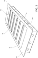
- each C-shaped element must also take into due consideration the presence of a plurality of through openings 14', spaced along an edge 15c of the plate 15 of each rib 14, provided at the points of intersection with the stringers 18 of the first panel 12a and/or the second panel 12b.
- each rib 14, made of composite material comprises a central plate 15, a first pair of flanges 15a and a second pair of flanges 15b, and has a plurality of openings 14', arranged spaced along an edge 15c of the plate 15.
- the first pair of flanges 15a and the second pair of flanges 15b are arranged at opposite ends of the plate 15, so as to obtain a conventional double-T cross-section.
- each rib 14 has a plurality of through openings 14' spaced along two opposed edges 15c of the plate 15, provided at the points of intersection with the stringers 18 of the first panel 12a, along an edge 15c, and of the second panel 12b, along an opposed edge 15c.
- openings 14' By virtue of the openings 14', it is possible to put two adjacent bays 11 in fluid communication with each other.
- the support inserts 20 By means of the support inserts 20, to be positioned in said openings 14', in contact with the ribs 14, as shown by Figure 3 , the stability of the shape of the openings 14' can be ensured even during the curing process, and the presence of resin accumulation or of other defects in their vicinity can be avoided.
- Each support insert 20 as shown in detail by Figure 5 , comprises a bridge element 20a, an extrados surface 20b, a intrados surface 20c and a base portion 20d, arranged to be placed either on the skin 16' of the first panel 12a or on a caul plate 23 placed on a stringer 18.
- the extrados surface 20b is arranged to be put in contact with a respective surface of an opening 14' of a rib 14.
- the shape of the extrados surface 20b will be, preferably, essentially complementary to the one of the opening 14'.
- the intrados surface 20c is, instead, arranged to be placed on a caul plate 23, therefore, preferably, it copies its external shape.
- the transverse cross-section shape of the support insert 20 determines the shape of the passage 14" that will be obtained in the curing process.
- the base portion 20d offers an enlarged support base to keep each support insert 20 correctly oriented.
- the base portion 20d may be provided as a pair of feet, as shown in Fig. 5 , for example shaped as a pair of parallel bars, essentially perpendicular to a plane passing by the middle line of the extrados surface 20b or of the intrados surface 20c, and extending at least partially on each side of such plane.
- the base portion may, alternatively, be provided as an enlarged truncated-pyramid base.
- Said support inserts 20 have, preferably, the same thickness of the rib 14, i.e. a cross-section in a longitudinal direction x at the extrados surface 20b has a thickness essentially equivalent to the one of the plate 15 of the rib 14, either equal or greater than that, and a shape such that it essentially fills the space between the flat cut of the openings 14' and the stringer 18 of the first or second panel 12a or 12b or the caul plate 23 on which they rest.
- the support inserts 20 are made in a plastic material resistant to the temperatures and the pressures typical of the curing process, like for example in a thermoplastic resin, when provided as rigid inserts, or in pre-cured silicon rubber, when provided as flexible inserts, and are free of sharp edges in order to avoid any damage to the film of the curing bag with which they will come in contact.
- a plastic material resistant to the temperatures and the pressures typical of the curing process like for example in a thermoplastic resin, when provided as rigid inserts, or in pre-cured silicon rubber, when provided as flexible inserts, and are free of sharp edges in order to avoid any damage to the film of the curing bag with which they will come in contact.
- a manufacturing process of a multi-ribbed wing box 10 made of composite material from a first and second panel 12a and 12b, and from a plurality of ribs 14, as just described, will now be described.
- the first panel 12a made of composite material, comprising the skin 16 and a plurality of stringers 18, is arranged on a suitable curing surface 22.
- a respective caul plate 23 is arranged on each stringer 18, in a way to cover it.
- each support insert 20 is placed on the first side 16' of the first panel 12a and/or on the caul plate 23.
- Said support inserts 20 are arranged aligned along the transverse direction y, essentially in correspondence of the points in which the subsequent arrangement of the ribs 14 crosses each stringer 18.
- each support insert 20 is arranged so that the respective intrados surface 20c rests on a respective caul plate 23, and each respective base portion 20d rests either on the skin 16' of the first panel 12a or on the caul plate 23 placed on the stringer 18, or on both the parts.
- the plurality of ribs 14, in this example two ribs 14, made of non-polymerized composite material, are placed on the first side 16' of the skin 16 of the first panel 12a.
- the first rib 14 is initially arranged along a transverse direction y, i.e. in a manner substantially perpendicular to the stringers 18.
- the first rib 14 is arranged by placing its respective first pair of flanges 15a in contact with the first side 16' of the skin 16 of the first panel 12a, so that the openings 14' are positioned in correspondence with the stringers 18, which will each extend through a respective opening 14'.
- each rib 14 is arranged so that the openings 14' are arranged in correspondence with the support inserts 20, by placing each opening 14' on the extrados surface 20b of a respective support insert 20.
- each rib 14 accommodates the respective support inserts 20 in the relative openings 14', by placing the intrados surfaces 20c of the support inserts 20 on a respective caul plate 23, and the base portions 20d of the support inserts 20 either on a respective caul plate 23, on the skin 16' of the first panel 12a, or on both the parts.
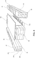
- a tool 24 may preferably be placed on said first side 16' of the skin 16 of the first panel 12a, in contact with the first rib 14.
- the tool 24 may also have the function of supporting the bag materials to be used in the curing process, which are arranged to totally wrap each tool 24, and which, being flexible (being, in effect, films and plastic fabrics) could not otherwise be located within the bays 11 - i.e. the spaces defined between two consecutive ribs 14 - for total and complete coverage of the composite surfaces to be polymerized.
- the tool 24 also has the function of distancing and holding the ribs 14 in the theoretical positions provided by design and allows the transfer of the plurality of ribs 14 (preformed and non-polymerized) onto the first panel 12a.
- the tool 24 has, preferably, dimensions suitably smaller than the theoretical inner surfaces of the bays, in order to guarantee sufficient space for the thickness of the bag materials to cover the tool.
- the tool 24 is provided with grooves 26, shaped to accommodate the stringers 18 and the caul plates 23 thereof.
- a tool provided with grooves 26 both on its top surface 28 and on its bottom surface 30, opposite to its top surface 28, is arranged to accommodate both stringers 18 of the first panel 12a and stringers 18 of the second panel 12b in said grooves 26.
- Said grooves 26 are, in particular, manufactured considering also the presence, in correspondence of the points of intersection of the ribs 14 and the stringers 18, of the respective support inserts 20.
- the tool 24 is made of low-mass density material, in particular, for example, a material having a mass density of less than 1.7 g/cm3, and in a configuration with high bending stiffness, in particular, for example, able to contain the bending strain within one millimetre per meter of length, this being in order to allow easy handling, even manually, of the tool 24, and to avoid any deformations that could be transferred to the ribs 14 in the fresh state during their positioning on the first panel 12a.
- the tools 24 are, preferably, made of resin or by using plastic materials, with or without reinforcements.
- the tool 24 is preferably capable of withstanding a positive pressure of at least 1 bar without collapsing, yielding or deforming, as during the dressing thereof with the bag materials the application of a vacuum may be envisaged.
- the tool 24 may be made of several modular parts, in particular at least three modular parts, to allow the extraction thereof from each bay after the closure with the second panel 12b, this being despite the undercuts offered by the configuration of the wing box 10, resulting both from the presence of stringers 18 on the skin 16 of the first panel 12a and on the skin 16 of the second panel 12b, and from any curved profile that the first and the second panel 12a and 12b may have.
- the tool 24 comprises a central part 24a, a bottom part 24b and a top part 24c, wherein the central part 24a is interposed between said bottom part 24b and said top part 24c, and is extractable along the transverse direction y.
- the constraint element 32 may comprise, for example, a plate which extends partially onto each of the parts of the tool 24, and which is bound to each part by conventional mechanical fastening elements, such as screws or bolts.
- the central part 24a of the tool 24 has, advantageously, a tapered section along the transverse direction y.
- the central part 24a of the tool has a section such that it may be pull out along the transverse direction y, for example a section that decreases linearly from one end of the central part 24a to the other along the transverse direction y.
- At least one among the central part 24a, the bottom part 24b and the top part 24c of the tool 24 has chamfers 34 adapted to improve the handling thereof.
- a second rib 14 is placed, in the same way as the first rib 14, on said skin 16 of the first panel 12a, along the transverse direction y, in contact with the tool 24, on the side opposite to the first rib 14.
- the plurality of ribs 14 and tools 24 may be loaded simultaneously on the side 16' of the skin 16.
- a first tool 24 placing it on its first lateral surface 25 - thus substantially rotating it by 90° - so as to have upwards a second lateral surface 27 thereof, opposite to the first lateral surface 25.
- a rib 14 on said first tool 24 placing the respective plate 15 on said second lateral surface 27.
- This step may, preferably, be carried out along two opposed edges 15c of the plate 15 of each rib 14, i.e. on all the openings 14' of the ribs 14.
- the assembly is then appropriately rotated and subsequently positioned on the skin 16 of the first panel 12a, so that each first pair of flanges 15a rests on said first side 16' of the first panel 12a and either that each opening 14' rests on a respective support insert 20 as previously positioned, or that each support insert 20 already inserted into the respective opening 14' rests on the caul plate 23 previously placed on the stringer.
- This operation may be coordinated with precision by means of suitable metallic systems of engagement arranged both on the curing surface 22 and at the ends of the tools 24.
- a rib 14 and a tool 24 are arranged alternately so that each pair of consecutive ribs 14 is in contact with a same tool 24.
- each tool 24 Before being placed inside a respective bay 11, i.e., in contact between a pair of consecutive ribs 14, each tool 24 may, preferably, be dressed with the bag materials necessary for the curing process in autoclave.
- the dressing may be carried out with bag materials typical of the vacuum bag curing process in autoclave, such as, for example, high-temperature nylon film, surface ventilation nylon or polyester fabric, high-temperature separator film. These may be arranged manually on each tool 24 in sequence, one on top of the other, forming, by using tapes and sealant, a tubular extension that completely wraps each tool 24, like a candy. Alternatively, the necessary bag materials may already be made in a tubular format, and fitted like a sock on each tool 24. After dressing, the vacuum may be applied to the outermost ply of the curing bag to ensure that the bag materials are adapted to the surfaces of each tool 24, avoiding wrinkling and bridging of the same materials.
- bag materials typical of the vacuum bag curing process in autoclave, such as, for example, high-temperature nylon film, surface ventilation nylon or polyester fabric, high-temperature separator film.
- the second panel 12b is arranged.
- the second panel 12b is placed in contact with each second pair of flanges 15b of each respective rib 14, covering each bay 11, i.e., the spaces between each pair of consecutive ribs 14. It is possible to arrange the support inserts 20 in contact with the skin 16 of the second panel 12b and/or with the caul plate 23 placed on the stringers 18 of the second panel 12b also in the openings 14' provided along the edge 15c of the plate 15 of the ribs 14 close to the second panel 12b, in a way similar to what explained with respect to the first panel 12a.
- the correct positioning of the second panel 12b may be ensured, for example, by mechanical coordination systems, such as existing male/female cones, or by other suitable known precision handling systems.
- first panel 12a made of already polymerized composite material, and, thus, to arrange a respective ply of high-temperature structural adhesive between each first pair of flanges 15a of each rib 14 and said first side 16' of the first panel 12a.
- second panel 12b made of already polymerized composite material, and thus to arrange a respective ply of high-temperature structural adhesive between each second pair of flanges 15b of each rib 14 and said first side 16' of the second panel 12b.
- first or second panel 12a or 12b of already polymerized composite material When a first or second panel 12a or 12b of already polymerized composite material is used, the curing process is called co-bonding and the ply of structural adhesive guarantees adhesion between the ribs 14 and the first or second panel 12a or 12b, respectively.
- a respective high-temperature release ply such as, for example, FEP or PTFE
- FEP or PTFE high-temperature release ply
- the second panel 12b may subsequently be mounted on the ribs 14 with traditional methods, taking advantage of the fact that, following the curing process, the profile of the second pair of flanges 15b has been moulded on the second panel 12b (except for the release film, which is generally very thin, for example, having a thickness of about 0.1 mm), facilitating the perfect coupling of the parts.
- a pair of tools 24 externally on said first side 16' of the skin 16 of the first panel 12a, respectively in contact with a first and a last rib 14.
- the process may be completed by sealing the respective ends of the curing bags of each tool 24 together and on the respective surfaces of the curing surface 22 and a respective top curing tool arranged on the second panel 12b, and with two additional strips of bag materials placed outside the wing box 10 on the outer tools 24.
- each tool 24 is pull out from the bays 11 and the external tools 24 are removed.
- the extraction of the tools 24 from the bays 11 is made possible by virtue of the particular configuration of each tool 24. Specifically, it is possible, first of all, to proceed with the extraction of the central part 24a, keeping, preferably, the top part 24c constrained, in order to avoid its fall by gravity. Then, the top part 24c may be removed, and finally the bottom part 24b.
- each tool 24 It is possible to extract or remove the central part 24a of each tool 24 solely by a pulling action in the transverse direction y. Then, the top part 24c and the bottom part 24b of each tool 24 are first moved in a vertical direction to bypass the undercuts inside the bays, and then pulled along the transverse direction y.
- the assembly comprising the first panel 12a, the plurality of ribs 14, and possibly the second panel 12, undergoes a curing process.
- the curing process is known per se and involves the application of a specific temperature and pressure cycle, and will not be described further.
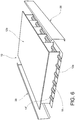
- the monolithic component thus obtained may be fitted with a corresponding front spar 36 and a corresponding rear spar 38 (shown in Figure 6 , known per se), manufactured separately as loose components, by means of a traditional assembly, to complete the wing box 10.
- the support inserts that ensure stability during the curing process and avoid resin accumulation close to the openings, it is possible to manufacture the openings before the curing process by flat cutting, and then maintain the shape of these openings during the curing process.
Landscapes
- Engineering & Computer Science (AREA)
- Aviation & Aerospace Engineering (AREA)
- Mechanical Engineering (AREA)
- Manufacturing & Machinery (AREA)
- Transportation (AREA)
- Fluid Mechanics (AREA)
- Physics & Mathematics (AREA)
- Architecture (AREA)
- Civil Engineering (AREA)
- Structural Engineering (AREA)
- Moulding By Coating Moulds (AREA)
- Casting Or Compression Moulding Of Plastics Or The Like (AREA)
- Laminated Bodies (AREA)
Applications Claiming Priority (1)
| Application Number | Priority Date | Filing Date | Title |
|---|---|---|---|
| IT102018000010326A IT201800010326A1 (it) | 2018-11-14 | 2018-11-14 | Procedimento per la fabbricazione di un cassone multi-centina in materiale composito con pannelli irrigiditi integrati e baie comunicanti |
Publications (2)
| Publication Number | Publication Date |
|---|---|
| EP3653372A1 true EP3653372A1 (de) | 2020-05-20 |
| EP3653372B1 EP3653372B1 (de) | 2022-06-15 |
Family
ID=65496886
Family Applications (1)
| Application Number | Title | Priority Date | Filing Date |
|---|---|---|---|
| EP19208436.6A Active EP3653372B1 (de) | 2018-11-14 | 2019-11-12 | Verfahren zur herstellung eines mehrrippigen flügelkastens aus verbundstoffmaterial mit integrierten versteiften platten und kommunikationsschächten |
Country Status (5)
| Country | Link |
|---|---|
| US (1) | US11097522B2 (de) |
| EP (1) | EP3653372B1 (de) |
| CN (1) | CN111186592A (de) |
| ES (1) | ES2924325T3 (de) |
| IT (1) | IT201800010326A1 (de) |
Families Citing this family (2)
| Publication number | Priority date | Publication date | Assignee | Title |
|---|---|---|---|---|
| GB2615755A (en) * | 2022-02-15 | 2023-08-23 | Airbus Operations Ltd | Fuel tank stringer with flow passage |
| CN121224156B (zh) * | 2025-12-02 | 2026-02-03 | 江苏新扬新材料股份有限公司 | 一种复合材料箱型梁的成型方法 |
Citations (2)
| Publication number | Priority date | Publication date | Assignee | Title |
|---|---|---|---|---|
| US5242523A (en) * | 1992-05-14 | 1993-09-07 | The Boeing Company | Caul and method for bonding and curing intricate composite structures |
| EP3150484A1 (de) * | 2015-09-29 | 2017-04-05 | Airbus Operations, S.L. | Verbundrippe für einen torsionskasten eines luftfahrzeugs und herstellungsverfahren dafür |
Family Cites Families (2)
| Publication number | Priority date | Publication date | Assignee | Title |
|---|---|---|---|---|
| JP5133446B2 (ja) * | 2011-01-21 | 2013-01-30 | 三菱航空機株式会社 | ベントストリンガ、航空機の主翼 |
| EP3210882A1 (de) * | 2016-02-08 | 2017-08-30 | Bell Helicopter Textron Inc. | Verbundflügelstruktur und verfahren zur herstellung |
-
2018
- 2018-11-14 IT IT102018000010326A patent/IT201800010326A1/it unknown
-
2019
- 2019-11-12 US US16/680,863 patent/US11097522B2/en active Active
- 2019-11-12 ES ES19208436T patent/ES2924325T3/es active Active
- 2019-11-12 EP EP19208436.6A patent/EP3653372B1/de active Active
- 2019-11-13 CN CN201911108013.XA patent/CN111186592A/zh active Pending
Patent Citations (2)
| Publication number | Priority date | Publication date | Assignee | Title |
|---|---|---|---|---|
| US5242523A (en) * | 1992-05-14 | 1993-09-07 | The Boeing Company | Caul and method for bonding and curing intricate composite structures |
| EP3150484A1 (de) * | 2015-09-29 | 2017-04-05 | Airbus Operations, S.L. | Verbundrippe für einen torsionskasten eines luftfahrzeugs und herstellungsverfahren dafür |
Also Published As
| Publication number | Publication date |
|---|---|
| ES2924325T3 (es) | 2022-10-06 |
| CN111186592A (zh) | 2020-05-22 |
| EP3653372B1 (de) | 2022-06-15 |
| US20200147947A1 (en) | 2020-05-14 |
| US11097522B2 (en) | 2021-08-24 |
| IT201800010326A1 (it) | 2020-05-14 |
Similar Documents
| Publication | Publication Date | Title |
|---|---|---|
| EP3653371B1 (de) | Verfahren zur herstellung eines mehrrippigen flügelkastens aus verbundwerkstoff mit integrierten versteiften platten | |
| EP2604405B1 (de) | Verfahren und Vorrichtung zum Herstellen von integrierten Tragflächen großer Dimensionen | |
| EP2889214B1 (de) | Hochintegriertes eingegossenes Gehäuse aus Verbundwerkstoff und Verfahren zur Herstellung | |
| CN103507941B (zh) | 复合材料帽形加筋件、复合材料帽形加筋压力腹板及其制造方法 | |
| US6245275B1 (en) | Method for fabricating composite structures | |
| EP0650825A1 (de) | Kompositstrukturen und Verfahren zum Herstellen derselben | |
| US20130115429A1 (en) | Composite structure and method of forming same | |
| EP3365159B1 (de) | Verfahren und vorrichtung für die herstellung einer haut-stringer-faserverbundstruktur | |
| CN102712144A (zh) | 双蒙皮结构 | |
| EP3533705B1 (de) | Stringerverbindung durch eine gemeinsame basis | |
| EP3789191B1 (de) | Verfahren zur herstellung einer verbundmaterialstruktur unter verwendung eines cohärtungsverfahrens | |
| EP3112116B1 (de) | Verfahren zur herstellung von platten aus mit geschlossenen holmen verstärktem verbundstoffmaterial | |
| EP3653372B1 (de) | Verfahren zur herstellung eines mehrrippigen flügelkastens aus verbundstoffmaterial mit integrierten versteiften platten und kommunikationsschächten | |
| CN113335492A (zh) | 用于桁条面板的复合板条支撑件 | |
| EP2774854B1 (de) | Triebwerksverkleidung und dessen Herstellungsverfahren | |
| EP3480002A1 (de) | Systeme und verfahren zur in-situ-herstellung von minimal bearbeiteten holmen | |
| EP4188794B1 (de) | Verfahren zur herstellung eines strukturbauteils aus verbundstoff mit versteifung mit mindestens einem stringer | |
| EP4188793B1 (de) | Verfahren zur herstellung eines strukturbauteils aus verbundstoff mit versteifung mit mindestens einem stringer | |
| JP2024163987A (ja) | 航空機のための複合材料のボックス形状の構造体を製造するための方法 |
Legal Events
| Date | Code | Title | Description |
|---|---|---|---|
| PUAI | Public reference made under article 153(3) epc to a published international application that has entered the european phase |
Free format text: ORIGINAL CODE: 0009012 |
|
| STAA | Information on the status of an ep patent application or granted ep patent |
Free format text: STATUS: THE APPLICATION HAS BEEN PUBLISHED |
|
| AK | Designated contracting states |
Kind code of ref document: A1 Designated state(s): AL AT BE BG CH CY CZ DE DK EE ES FI FR GB GR HR HU IE IS IT LI LT LU LV MC MK MT NL NO PL PT RO RS SE SI SK SM TR |
|
| AX | Request for extension of the european patent |
Extension state: BA ME |
|
| STAA | Information on the status of an ep patent application or granted ep patent |
Free format text: STATUS: REQUEST FOR EXAMINATION WAS MADE |
|
| 17P | Request for examination filed |
Effective date: 20201118 |
|
| RBV | Designated contracting states (corrected) |
Designated state(s): AL AT BE BG CH CY CZ DE DK EE ES FI FR GB GR HR HU IE IS IT LI LT LU LV MC MK MT NL NO PL PT RO RS SE SI SK SM TR |
|
| STAA | Information on the status of an ep patent application or granted ep patent |
Free format text: STATUS: EXAMINATION IS IN PROGRESS |
|
| 17Q | First examination report despatched |
Effective date: 20210302 |
|
| GRAP | Despatch of communication of intention to grant a patent |
Free format text: ORIGINAL CODE: EPIDOSNIGR1 |
|
| STAA | Information on the status of an ep patent application or granted ep patent |
Free format text: STATUS: GRANT OF PATENT IS INTENDED |
|
| INTG | Intention to grant announced |
Effective date: 20220111 |
|
| GRAS | Grant fee paid |
Free format text: ORIGINAL CODE: EPIDOSNIGR3 |
|
| GRAA | (expected) grant |
Free format text: ORIGINAL CODE: 0009210 |
|
| STAA | Information on the status of an ep patent application or granted ep patent |
Free format text: STATUS: THE PATENT HAS BEEN GRANTED |
|
| AK | Designated contracting states |
Kind code of ref document: B1 Designated state(s): AL AT BE BG CH CY CZ DE DK EE ES FI FR GB GR HR HU IE IS IT LI LT LU LV MC MK MT NL NO PL PT RO RS SE SI SK SM TR |
|
| REG | Reference to a national code |
Ref country code: CH Ref legal event code: EP Ref country code: GB Ref legal event code: FG4D |
|
| REG | Reference to a national code |
Ref country code: IE Ref legal event code: FG4D |
|
| REG | Reference to a national code |
Ref country code: DE Ref legal event code: R096 Ref document number: 602019015860 Country of ref document: DE |
|
| REG | Reference to a national code |
Ref country code: AT Ref legal event code: REF Ref document number: 1498113 Country of ref document: AT Kind code of ref document: T Effective date: 20220715 |
|
| REG | Reference to a national code |
Ref country code: ES Ref legal event code: FG2A Ref document number: 2924325 Country of ref document: ES Kind code of ref document: T3 Effective date: 20221006 |
|
| REG | Reference to a national code |
Ref country code: LT Ref legal event code: MG9D |
|
| REG | Reference to a national code |
Ref country code: NL Ref legal event code: MP Effective date: 20220615 |
|
| PG25 | Lapsed in a contracting state [announced via postgrant information from national office to epo] |
Ref country code: SE Free format text: LAPSE BECAUSE OF FAILURE TO SUBMIT A TRANSLATION OF THE DESCRIPTION OR TO PAY THE FEE WITHIN THE PRESCRIBED TIME-LIMIT Effective date: 20220615 Ref country code: NO Free format text: LAPSE BECAUSE OF FAILURE TO SUBMIT A TRANSLATION OF THE DESCRIPTION OR TO PAY THE FEE WITHIN THE PRESCRIBED TIME-LIMIT Effective date: 20220915 Ref country code: LT Free format text: LAPSE BECAUSE OF FAILURE TO SUBMIT A TRANSLATION OF THE DESCRIPTION OR TO PAY THE FEE WITHIN THE PRESCRIBED TIME-LIMIT Effective date: 20220615 Ref country code: HR Free format text: LAPSE BECAUSE OF FAILURE TO SUBMIT A TRANSLATION OF THE DESCRIPTION OR TO PAY THE FEE WITHIN THE PRESCRIBED TIME-LIMIT Effective date: 20220615 Ref country code: GR Free format text: LAPSE BECAUSE OF FAILURE TO SUBMIT A TRANSLATION OF THE DESCRIPTION OR TO PAY THE FEE WITHIN THE PRESCRIBED TIME-LIMIT Effective date: 20220916 Ref country code: FI Free format text: LAPSE BECAUSE OF FAILURE TO SUBMIT A TRANSLATION OF THE DESCRIPTION OR TO PAY THE FEE WITHIN THE PRESCRIBED TIME-LIMIT Effective date: 20220615 Ref country code: BG Free format text: LAPSE BECAUSE OF FAILURE TO SUBMIT A TRANSLATION OF THE DESCRIPTION OR TO PAY THE FEE WITHIN THE PRESCRIBED TIME-LIMIT Effective date: 20220915 |
|
| REG | Reference to a national code |
Ref country code: AT Ref legal event code: MK05 Ref document number: 1498113 Country of ref document: AT Kind code of ref document: T Effective date: 20220615 |
|
| PG25 | Lapsed in a contracting state [announced via postgrant information from national office to epo] |
Ref country code: RS Free format text: LAPSE BECAUSE OF FAILURE TO SUBMIT A TRANSLATION OF THE DESCRIPTION OR TO PAY THE FEE WITHIN THE PRESCRIBED TIME-LIMIT Effective date: 20220615 Ref country code: LV Free format text: LAPSE BECAUSE OF FAILURE TO SUBMIT A TRANSLATION OF THE DESCRIPTION OR TO PAY THE FEE WITHIN THE PRESCRIBED TIME-LIMIT Effective date: 20220615 |
|
| PG25 | Lapsed in a contracting state [announced via postgrant information from national office to epo] |
Ref country code: NL Free format text: LAPSE BECAUSE OF FAILURE TO SUBMIT A TRANSLATION OF THE DESCRIPTION OR TO PAY THE FEE WITHIN THE PRESCRIBED TIME-LIMIT Effective date: 20220615 |
|
| PG25 | Lapsed in a contracting state [announced via postgrant information from national office to epo] |
Ref country code: SM Free format text: LAPSE BECAUSE OF FAILURE TO SUBMIT A TRANSLATION OF THE DESCRIPTION OR TO PAY THE FEE WITHIN THE PRESCRIBED TIME-LIMIT Effective date: 20220615 Ref country code: SK Free format text: LAPSE BECAUSE OF FAILURE TO SUBMIT A TRANSLATION OF THE DESCRIPTION OR TO PAY THE FEE WITHIN THE PRESCRIBED TIME-LIMIT Effective date: 20220615 Ref country code: RO Free format text: LAPSE BECAUSE OF FAILURE TO SUBMIT A TRANSLATION OF THE DESCRIPTION OR TO PAY THE FEE WITHIN THE PRESCRIBED TIME-LIMIT Effective date: 20220615 Ref country code: PT Free format text: LAPSE BECAUSE OF FAILURE TO SUBMIT A TRANSLATION OF THE DESCRIPTION OR TO PAY THE FEE WITHIN THE PRESCRIBED TIME-LIMIT Effective date: 20221017 Ref country code: EE Free format text: LAPSE BECAUSE OF FAILURE TO SUBMIT A TRANSLATION OF THE DESCRIPTION OR TO PAY THE FEE WITHIN THE PRESCRIBED TIME-LIMIT Effective date: 20220615 Ref country code: CZ Free format text: LAPSE BECAUSE OF FAILURE TO SUBMIT A TRANSLATION OF THE DESCRIPTION OR TO PAY THE FEE WITHIN THE PRESCRIBED TIME-LIMIT Effective date: 20220615 Ref country code: AT Free format text: LAPSE BECAUSE OF FAILURE TO SUBMIT A TRANSLATION OF THE DESCRIPTION OR TO PAY THE FEE WITHIN THE PRESCRIBED TIME-LIMIT Effective date: 20220615 |
|
| PG25 | Lapsed in a contracting state [announced via postgrant information from national office to epo] |
Ref country code: PL Free format text: LAPSE BECAUSE OF FAILURE TO SUBMIT A TRANSLATION OF THE DESCRIPTION OR TO PAY THE FEE WITHIN THE PRESCRIBED TIME-LIMIT Effective date: 20220615 Ref country code: IS Free format text: LAPSE BECAUSE OF FAILURE TO SUBMIT A TRANSLATION OF THE DESCRIPTION OR TO PAY THE FEE WITHIN THE PRESCRIBED TIME-LIMIT Effective date: 20221015 |
|
| REG | Reference to a national code |
Ref country code: DE Ref legal event code: R097 Ref document number: 602019015860 Country of ref document: DE |
|
| PG25 | Lapsed in a contracting state [announced via postgrant information from national office to epo] |
Ref country code: AL Free format text: LAPSE BECAUSE OF FAILURE TO SUBMIT A TRANSLATION OF THE DESCRIPTION OR TO PAY THE FEE WITHIN THE PRESCRIBED TIME-LIMIT Effective date: 20220615 |
|
| PLBE | No opposition filed within time limit |
Free format text: ORIGINAL CODE: 0009261 |
|
| STAA | Information on the status of an ep patent application or granted ep patent |
Free format text: STATUS: NO OPPOSITION FILED WITHIN TIME LIMIT |
|
| PG25 | Lapsed in a contracting state [announced via postgrant information from national office to epo] |
Ref country code: DK Free format text: LAPSE BECAUSE OF FAILURE TO SUBMIT A TRANSLATION OF THE DESCRIPTION OR TO PAY THE FEE WITHIN THE PRESCRIBED TIME-LIMIT Effective date: 20220615 |
|
| 26N | No opposition filed |
Effective date: 20230316 |
|
| PG25 | Lapsed in a contracting state [announced via postgrant information from national office to epo] |
Ref country code: SI Free format text: LAPSE BECAUSE OF FAILURE TO SUBMIT A TRANSLATION OF THE DESCRIPTION OR TO PAY THE FEE WITHIN THE PRESCRIBED TIME-LIMIT Effective date: 20220615 |
|
| PG25 | Lapsed in a contracting state [announced via postgrant information from national office to epo] |
Ref country code: MC Free format text: LAPSE BECAUSE OF FAILURE TO SUBMIT A TRANSLATION OF THE DESCRIPTION OR TO PAY THE FEE WITHIN THE PRESCRIBED TIME-LIMIT Effective date: 20220615 |
|
| REG | Reference to a national code |
Ref country code: CH Ref legal event code: PL |
|
| REG | Reference to a national code |
Ref country code: BE Ref legal event code: MM Effective date: 20221130 |
|
| PG25 | Lapsed in a contracting state [announced via postgrant information from national office to epo] |
Ref country code: LI Free format text: LAPSE BECAUSE OF NON-PAYMENT OF DUE FEES Effective date: 20221130 Ref country code: CH Free format text: LAPSE BECAUSE OF NON-PAYMENT OF DUE FEES Effective date: 20221130 |
|
| PG25 | Lapsed in a contracting state [announced via postgrant information from national office to epo] |
Ref country code: LU Free format text: LAPSE BECAUSE OF NON-PAYMENT OF DUE FEES Effective date: 20221112 |
|
| PG25 | Lapsed in a contracting state [announced via postgrant information from national office to epo] |
Ref country code: IE Free format text: LAPSE BECAUSE OF NON-PAYMENT OF DUE FEES Effective date: 20221112 |
|
| PG25 | Lapsed in a contracting state [announced via postgrant information from national office to epo] |
Ref country code: BE Free format text: LAPSE BECAUSE OF NON-PAYMENT OF DUE FEES Effective date: 20221130 |
|
| PG25 | Lapsed in a contracting state [announced via postgrant information from national office to epo] |
Ref country code: HU Free format text: LAPSE BECAUSE OF FAILURE TO SUBMIT A TRANSLATION OF THE DESCRIPTION OR TO PAY THE FEE WITHIN THE PRESCRIBED TIME-LIMIT; INVALID AB INITIO Effective date: 20191112 |
|
| PG25 | Lapsed in a contracting state [announced via postgrant information from national office to epo] |
Ref country code: CY Free format text: LAPSE BECAUSE OF FAILURE TO SUBMIT A TRANSLATION OF THE DESCRIPTION OR TO PAY THE FEE WITHIN THE PRESCRIBED TIME-LIMIT Effective date: 20220615 |
|
| PG25 | Lapsed in a contracting state [announced via postgrant information from national office to epo] |
Ref country code: MK Free format text: LAPSE BECAUSE OF FAILURE TO SUBMIT A TRANSLATION OF THE DESCRIPTION OR TO PAY THE FEE WITHIN THE PRESCRIBED TIME-LIMIT Effective date: 20220615 |
|
| PG25 | Lapsed in a contracting state [announced via postgrant information from national office to epo] |
Ref country code: TR Free format text: LAPSE BECAUSE OF FAILURE TO SUBMIT A TRANSLATION OF THE DESCRIPTION OR TO PAY THE FEE WITHIN THE PRESCRIBED TIME-LIMIT Effective date: 20220615 |
|
| PG25 | Lapsed in a contracting state [announced via postgrant information from national office to epo] |
Ref country code: MT Free format text: LAPSE BECAUSE OF FAILURE TO SUBMIT A TRANSLATION OF THE DESCRIPTION OR TO PAY THE FEE WITHIN THE PRESCRIBED TIME-LIMIT Effective date: 20220615 |
|
| PG25 | Lapsed in a contracting state [announced via postgrant information from national office to epo] |
Ref country code: BG Free format text: LAPSE BECAUSE OF FAILURE TO SUBMIT A TRANSLATION OF THE DESCRIPTION OR TO PAY THE FEE WITHIN THE PRESCRIBED TIME-LIMIT Effective date: 20220615 |
|
| PG25 | Lapsed in a contracting state [announced via postgrant information from national office to epo] |
Ref country code: BG Free format text: LAPSE BECAUSE OF FAILURE TO SUBMIT A TRANSLATION OF THE DESCRIPTION OR TO PAY THE FEE WITHIN THE PRESCRIBED TIME-LIMIT Effective date: 20220615 |
|
| PGFP | Annual fee paid to national office [announced via postgrant information from national office to epo] |
Ref country code: IT Payment date: 20250908 Year of fee payment: 7 |
|
| PGFP | Annual fee paid to national office [announced via postgrant information from national office to epo] |
Ref country code: DE Payment date: 20251125 Year of fee payment: 7 |
|
| PGFP | Annual fee paid to national office [announced via postgrant information from national office to epo] |
Ref country code: GB Payment date: 20251121 Year of fee payment: 7 |
|
| PGFP | Annual fee paid to national office [announced via postgrant information from national office to epo] |
Ref country code: FR Payment date: 20251107 Year of fee payment: 7 |
|
| PGFP | Annual fee paid to national office [announced via postgrant information from national office to epo] |
Ref country code: ES Payment date: 20251201 Year of fee payment: 7 |