EP3653780A1 - Appareil électroménager comportant une carrosserie, une porte et un dispositif de liaison reliant la porte à la carrosserie - Google Patents
Appareil électroménager comportant une carrosserie, une porte et un dispositif de liaison reliant la porte à la carrosserie Download PDFInfo
- Publication number
- EP3653780A1 EP3653780A1 EP19208762.5A EP19208762A EP3653780A1 EP 3653780 A1 EP3653780 A1 EP 3653780A1 EP 19208762 A EP19208762 A EP 19208762A EP 3653780 A1 EP3653780 A1 EP 3653780A1
- Authority
- EP
- European Patent Office
- Prior art keywords
- door
- opening
- household appliance
- plane
- angle
- Prior art date
- Legal status (The legal status is an assumption and is not a legal conclusion. Google has not performed a legal analysis and makes no representation as to the accuracy of the status listed.)
- Granted
Links
Images


Classifications
-
- D—TEXTILES; PAPER
- D06—TREATMENT OF TEXTILES OR THE LIKE; LAUNDERING; FLEXIBLE MATERIALS NOT OTHERWISE PROVIDED FOR
- D06F—LAUNDERING, DRYING, IRONING, PRESSING OR FOLDING TEXTILE ARTICLES
- D06F39/00—Details of washing machines not specific to a single type of machines covered by groups D06F9/00 - D06F27/00
- D06F39/12—Casings; Tubs
- D06F39/14—Doors or covers; Securing means therefor
-
- E—FIXED CONSTRUCTIONS
- E05—LOCKS; KEYS; WINDOW OR DOOR FITTINGS; SAFES
- E05D—HINGES OR SUSPENSION DEVICES FOR DOORS, WINDOWS OR WINGS
- E05D3/00—Hinges with pins
- E05D3/06—Hinges with pins with two or more pins
- E05D3/10—Hinges with pins with two or more pins with non-parallel pins
-
- E—FIXED CONSTRUCTIONS
- E05—LOCKS; KEYS; WINDOW OR DOOR FITTINGS; SAFES
- E05Y—INDEXING SCHEME ASSOCIATED WITH SUBCLASSES E05D AND E05F, RELATING TO CONSTRUCTION ELEMENTS, ELECTRIC CONTROL, POWER SUPPLY, POWER SIGNAL OR TRANSMISSION, USER INTERFACES, MOUNTING OR COUPLING, DETAILS, ACCESSORIES, AUXILIARY OPERATIONS NOT OTHERWISE PROVIDED FOR, APPLICATION THEREOF
- E05Y2201/00—Constructional elements; Accessories therefor
- E05Y2201/60—Suspension or transmission members; Accessories therefor
- E05Y2201/622—Suspension or transmission members elements
- E05Y2201/624—Arms
-
- E—FIXED CONSTRUCTIONS
- E05—LOCKS; KEYS; WINDOW OR DOOR FITTINGS; SAFES
- E05Y—INDEXING SCHEME ASSOCIATED WITH SUBCLASSES E05D AND E05F, RELATING TO CONSTRUCTION ELEMENTS, ELECTRIC CONTROL, POWER SUPPLY, POWER SIGNAL OR TRANSMISSION, USER INTERFACES, MOUNTING OR COUPLING, DETAILS, ACCESSORIES, AUXILIARY OPERATIONS NOT OTHERWISE PROVIDED FOR, APPLICATION THEREOF
- E05Y2800/00—Details, accessories and auxiliary operations not otherwise provided for
- E05Y2800/26—Form or shape
- E05Y2800/266—Form or shape curved
-
- E—FIXED CONSTRUCTIONS
- E05—LOCKS; KEYS; WINDOW OR DOOR FITTINGS; SAFES
- E05Y—INDEXING SCHEME ASSOCIATED WITH SUBCLASSES E05D AND E05F, RELATING TO CONSTRUCTION ELEMENTS, ELECTRIC CONTROL, POWER SUPPLY, POWER SIGNAL OR TRANSMISSION, USER INTERFACES, MOUNTING OR COUPLING, DETAILS, ACCESSORIES, AUXILIARY OPERATIONS NOT OTHERWISE PROVIDED FOR, APPLICATION THEREOF
- E05Y2900/00—Application of doors, windows, wings or fittings thereof
- E05Y2900/30—Application of doors, windows, wings or fittings thereof for domestic appliances
- E05Y2900/312—Application of doors, windows, wings or fittings thereof for domestic appliances for washing machines or laundry dryers
Definitions
- the present invention relates to a household appliance comprising a body, a door and a connection device connecting the door to the body.
- the opening is formed in an external wall extending in a first vertical plane.
- the opening is closed, at least part of the door bears against the bodywork either directly against the external wall, or against a protruding part or prominent part of constant thickness which can be placed on the external wall of the bodywork around the opening and extending in a plane parallel to the first vertical plane of the external wall of the bodywork.
- the door is configured to ensure the correct closing of the opening.
- a connecting device generally connects the body to the door and allows the door to rotate relative to the body.
- connection device described in this document comprises a first fixing support fixed to the door, a second fixing support fixed to the body and a central part connecting the first and second fixing supports.
- the first and second fixing supports respectively comprise a first pivot link along a front axis and a second pivot link along a rear axis allowing the door to rotate relative to the body.
- the two front and rear axes extend in two directions parallel to each other.
- connection device allows good sealing of the opening when the door, once in the closed position, extends parallel to the external wall of the bodywork and to the projecting part when the latter is formed on the external wall around the opening.
- the present invention aims to provide such a connecting device.
- the invention relates to a household appliance comprising a body, a door and a connecting device connecting the door to the body.
- the body includes an outer wall extending in a first vertical plane and in which an opening is formed.
- the connection device is fixed to the door by a first pivot connection around a first axis called the front axis and to the bodywork by a second pivot connection around a second axis called the rear axis, the door being configured to pivot relative to to the bodywork between a closed position in which the opening is closed and a maximum opening position.
- the rear axis extends in a first vertical direction and the front axis extends in a second inclined direction not parallel to the first direction, the first direction and the second direction forming between them a first non-zero angle.
- the inclination of the front axis with respect to the vertical rear axis allows the door not to be hindered by a prominent part disposed on the external wall at the periphery of the opening. The correct closing of the opening is thus ensured.
- the second direction when the door is in the closed position, the second direction extends in a vertical plane perpendicular to the first plane.
- the body includes a prominent part disposed at the periphery of the opening.
- the first angle is greater than or equal to a second angle formed by the intersection of the first plane and a second plane tangent to the part.
- the first angle formed between the axes being at least equal to the second angle formed between the planes makes it possible to compensate for the inclination of the second plane and thus guarantee a good closure of the opening.
- the first angle and the second angle are between 1 ° and 5 °, and preferably equal to 2.5 °.
- the part forms a continuous frame over the entire periphery of the opening.
- the part is arranged only on a part of the periphery of the opening.
- the part has a variable thickness and comprises a first part having a maximum thickness and a second part having a minimum thickness.
- the first part is formed in a lower part of the opening and the second part is formed in a upper part of the opening.
- the second direction is parallel to a second plane tangent to the first part and to the second part of the room.
- the second direction being parallel to the second plane, the first angle and the second angle are thus equal.
- connection device comprises a central part connecting the first pivot connection to the second pivot connection.
- the thickness of the part of variable thickness varies linearly between the first part and the second part.
- the household appliance is a washing machine.
- the figure 1 represents a washing machine 1 with front loading or household appliance 1 according to an embodiment according to the invention.
- the washing machine 1 has a body 2 and a door 3.
- the bodywork 2 constitutes an external envelope of a washing tank.
- the body 2 has a substantially parallelepiped shape.
- the body has external walls, and in particular a front external wall.
- the external wall 20 comprises a lower edge 201, an upper edge 202 and two lateral edges 203, 204.
- the external wall 20 here extends in a first plane P1.
- the first plane P1 is substantially vertical.
- the outer wall 20 is slightly curved.
- the external wall 20 includes an opening 21, visible in particular at the figure 2 .
- the opening 21 is here circular.
- the opening 21 gives access to a frame 22 and to a drum 23 in which linen is treated.
- the frame 22 is formed upstream of the drum 23.
- the frame 22 of the body 2 is here annular.
- the drum 23 has a cylindrical shape and comprises an annular edge 231 forming the inlet of the drum 23.
- the frame 22 and the annular edge 231 of the drum 23 have substantially the same diameter.
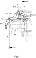
- the body 2 comprises on the external wall 20 a part 24, clearly visible at the figure 3 .
- the part 24 is formed at the periphery of the opening 21, that is to say near the opening.
- the part 24 is here formed around the opening 21.
- the part 24 is prominent from the external wall 20.
- the part 24 has a variable thickness depending on the parts.
- the part 24 comprises at least a first part 241 or thick part having a maximum thickness and at least a second part 242 or thin part having a minimum thickness.
- the thickness of the part of variable thickness here varies linearly between the first part 241 and the second part 242.
- thickness is meant the dimension of the part in a direction perpendicular to the first plane P1.
- the thickness is measured from the external wall 20.
- the maximum thickness is understood to mean the greatest thickness formed in the part 24 and by minimum thickness the smallest thickness formed in the part 24.
- the first part has a thickness greater than the thickness of the second part.
- the part 24 extends in a second plane P2.
- the second plane P2 is defined as being a plane tangent to the part 24.
- the second plane P2 is here tangent to the thick part and to the thin part of the part 24.
- the second plane P2 is inclined relative to the first vertical plane P1 .
- the first plane P1 and the second plane P2 are intersecting.
- the first plane P1 is inclined relative to the second plane P2 at an angle called the second angle ⁇ .
- the first part 241 or thick part of the part 24 is here formed in a lower part of the opening 21.
- the second part 242 or thin part is here formed in an upper part of the opening 21.
- the part 24 here forms a frame around the opening 21.
- the part 24 is therefore a continuous part.
- the part 24 has an annular shape.
- the opening 21 and the part 24 have substantially the same diameter.
- the part 24 has the same internal diameter as a diameter of the opening 21.
- the part 24 can have different shapes and dimensions and can be arranged otherwise.
- the part 24 may not completely surround the opening 21.
- the part 24 disposed only at a part of the periphery of the opening can either have a variable thickness or a constant thickness.
- the part 24 may be discontinuous, for example in the form of two separate parts, each having a different thickness.
- the door 3 has the shape of a porthole comprising a transparent glass 31 and a frame 32.
- the frame 32 has an annular shape and has an external face 321 and an internal face 322.
- the glass 31 is secured to the frame 32 at the periphery of the internal face 322.
- the glass 31 has the shape of a re-entrant bowl in direction of the interior of the drum 23 when the door 3 is closed.
- the glass 31 includes a lower rounded edge 311 and a curved portion 312. The door 3 takes a closed position when the opening 21 is closed.
- the washing machine 1 has a seal commonly called a cuff 4, disposed at the inlet of the drum 23.
- the cuff 4 has a substantially annular shape.
- the cuff 4 is made of flexible material.
- the cuff 4 is dimensioned so as to match the annular edge 231 of the drum 23.
- the cuff 4 is also dimensioned to conform to the shape of the rounded lower edge 311 when the door 3 is closed. When the door 3 is closed, the lower rounded edge 311 bears against the cuff 4.
- the cuff 4 is configured to seal the washing machine.
- the washing machine 1 comprises a connection device 5 making it possible to connect the bodywork 2 to the door 3.
- the connecting device 5 comprises a first fixing support 51 fixed to the door 3, a second fixing support 52 fixed to the body 2 and a central part 53 connecting the first fixing support 51 to the second fixing support 52.
- the first fixing support 51 is fixed to the frame 32 of the door 3.
- the first fixing support 51 is here fixed to the internal face 322.
- the first fixing support 51 is fixed to the frame 32 by any means already known in the prior art, for example by means of screws.
- the first fixing support 51 comprises a first front orifice 511.
- the second fixing support 52 is fixed to the bodywork 2.
- the second fixing support 52 is here fixed to the frame 22.
- the second fixing support 52 is fixed to the bodywork by any means conventionally used and known in the prior art.
- the second fixing support 52 comprises a first rear opening 521.
- the central part 53 here has a C shape.
- the central part 53 comprises a second front port 531 and a second rear port 532.
- the second front ports 531 and rear 532 are here formed on either side of the central part.
- the central part 53 is assembled on the one hand to the first fixing support 51 so that the first front orifice 511 of the first fixing support 51 is disposed opposite the second front orifice 531 of the central part 53. And on the other hand, the central part 53 is assembled to the second fixing support 52 so that the first rear opening 521 of the second fixing support 52 is arranged opposite the second rear opening 532 of the central part 53.
- the first and second front holes 511, 531 of the first fixing support 51 and of the central part 53 are configured to receive a front pivot axis, also called first axis or front axis 512.
- the first and second rear holes 521, 532 of the second fixing support 52 and central part 53 are configured to receive a rear pivot axis, also called second axis or rear axis 522.
- the connecting device 5 thus formed is a hinge with two pivot axes, the front axis 512 and the rear axis 522.
- the first fixing support 51 and the front axis 512 form a first pivot connection.
- the second fixing support 52 and the rear axle 522 form a second pivot link.
- the connecting device 5 allows the door 3 to rotate relative to the bodywork 2.
- the central part 53 moves in a horizontal plane.
- the frame 22 comprises a cavity 221.
- the cavity 221 allows the passage of the central part 53.
- the cavity 221 has dimensions at least equal to those of the central part 53 in order to allow its passage and its rotation.
- the connecting device 5 allows the rotation of the door 3 between the closed position or closed position and a maximum open position.
- maximum opening position is meant the position in which the central part 53 can no longer move horizontally.
- the door 3 can pivot up to 55 ° along the front axis 512. In other words, the door 3 can pivot by 55 ° relative to the central part 53.
- the central part 53 can pivot up to 70 ° along the rear axis 522. In other words, the central part 53 can pivot by 70 ° relative to the body 2. In other words, the door 3 can pivot by 125 ° by compared to bodywork 2.
- the rear axis 522 extends in a first vertical direction D1 and the front axis 512 extends in a second inclined direction D2.
- the second direction D2 is inclined towards the thin part having the smallest thickness of the part 24.
- the second direction D2 is here inclined towards the upper part 242 of the part 24.
- the first direction of the rear axis 522 and the second direction D2 of the front axis 512 form an angle called the first angle ⁇ .
- the first angle ⁇ is not zero.
- the first angle ⁇ is at least equal to the second angle ⁇ formed by the first plane P1 and the second plane P2.
- the second direction D2 is here parallel to the second plane P2.
- the first angle ⁇ is in this embodiment equal to the second angle ⁇ .
- the first angle ⁇ and the second angle ⁇ are between 1 ° and 5 °. Preferably, the first angle ⁇ and the second angle ⁇ are equal to 2.5 °.
- the device thus formed allows the complete closing of the door 3 and thus the perfect sealing of the opening 21.
- the first angle ⁇ being greater than or equal to the second angle ⁇ and the front axis being inclined towards the thin part of the part 24, the closing of the door is not hampered by the presence of the part 24 of variable thickness.
- the inclination of the front axis 512 along the first angle ⁇ greater than or equal to the second angle ⁇ makes it possible to compensate for the inclination of the part 24.
- this allows the vertical plane of the door 3 to rest against the cuff 4.
- the lower rounded edge 311 bears against the cuff 4.
- a sealed closure of the opening 21 is thus ensured. Sealing the opening 21 is particularly important for devices appliances such as washing machines involving the use of water which may cause leaks.
- the present invention is not limited to the embodiment described above.
- the prominent part has been described as having a variable thickness.
- the protruding part can indeed have a constant thickness and be formed only at a part of the periphery of the opening.
- the second angle ⁇ is formed between a plane tangent to the protruding part and inclined towards the external wall.
- the first angle ⁇ formed by the first and second directions is greater than or equal to the second angle ⁇ .
- the front axle is inclined so as to allow the door to close. The door is no longer hampered by the prominent part.
- the prominent part of constant thickness can be formed in the lower part of the opening.
- the second direction D2 and the second plane P2 both have an inclination of the protruding part towards the upper part of the opening.
Landscapes
- Engineering & Computer Science (AREA)
- Mechanical Engineering (AREA)
- Textile Engineering (AREA)
- Main Body Construction Of Washing Machines And Laundry Dryers (AREA)
- Extensible Doors And Revolving Doors (AREA)
- Specific Sealing Or Ventilating Devices For Doors And Windows (AREA)
- Securing Of Glass Panes Or The Like (AREA)
- Door And Window Frames Mounted To Openings (AREA)
Abstract
Description
- La présente invention concerne un appareil électroménager comportant une carrosserie, une porte et un dispositif de liaison reliant la porte à la carrosserie.
- De manière générale, un appareil électroménager tel qu'un appareil à traiter le linge comporte une carrosserie dans laquelle est formée une ouverture, et une porte permettant d'obturer l'ouverture.
- Classiquement, l'ouverture est formée dans une paroi externe s'étendant dans un premier plan vertical. Lors de l'obturation de l'ouverture, au moins une partie de la porte est en appui contre la carrosserie soit directement contre la paroi externe, soit contre une pièce saillante ou pièce proéminente d'épaisseur constante pouvant être disposée sur la paroi externe de la carrosserie autour de l'ouverture et s'étendant dans un plan parallèle au premier plan vertical de la paroi externe de la carrosserie. La porte est configurée pour assurer la bonne obturation de l'ouverture.
- Un dispositif de liaison relie généralement la carrosserie à la porte et permet la rotation de la porte par rapport à la carrosserie.
- En particulier, on connait dans l'art antérieur un dispositif de liaison décrit dans le document
EP 3 124 669 et formé d'une charnière à deux axes reliant une porte d'un appareil lave-linge à sa carrosserie et permettant la rotation de la porte par rapport à la carrosserie. - Plus précisément, le dispositif de liaison décrit dans ce document comprend un premier support de fixation fixé à la porte, un deuxième support de fixation fixé à la carrosserie et une pièce centrale reliant les premier et deuxième supports de fixation. Les premier et deuxième supports de fixation comprennent respectivement une première liaison pivot selon un axe avant et une deuxième liaison pivot selon un axe arrière permettant la rotation de la porte par rapport à la carrosserie. Les deux axes avant et arrière s'étendent suivant deux directions parallèles entre elles.
- Ce type de dispositif de liaison permet une bonne obturation de l'ouverture lorsque la porte une fois en position fermée s'étend parallèlement à la paroi externe de la carrosserie et à la pièce saillante lorsque celle-ci est formée sur la paroi externe autour de l'ouverture.
- Cependant, pour diverses raisons, il peut être intéressant de disposer uniquement sur une partie de la périphérie de l'ouverture, une pièce proéminente. En l'occurrence, on peut vouloir intégrer à la paroi externe de la carrosserie un dispositif spécifique, par exemple un dispositif d'éclairage et/ou de détection de linge qui formerait la pièce proéminente à la périphérie de l'ouverture d'une machine à traiter le linge. Ou encore, pour des raisons esthétiques par exemple, il peut être intéressant de former une pièce d'épaisseur variable à la périphérie de l'ouverture de la carrosserie de l'appareil électroménager.
- L'existence de telles pièces proéminentes rend alors impossible l'utilisation d'un dispositif de liaison tel que celui décrit dans le document
EP 3 124 669 . En effet, la porte serait gênée par la pièce proéminente lors de l'obturation de l'ouverture. - Aussi, il existe un besoin d'un dispositif de liaison entre la carrosserie et la porte d'appareil électroménager permettant la bonne fermeture de la porte et ainsi une parfaite obturation de l'ouverture lorsqu'une pièce proéminente est disposée à proximité de l'ouverture ou lorsqu'une pièce d'épaisseur variable est formée sur toute la périphérie de l'ouverture.
- La présente invention a pour but de proposer un tel dispositif de liaison.
- Ainsi, l'invention concerne un appareil électroménager comportant une carrosserie, une porte et un dispositif de liaison reliant la porte à la carrosserie. La carrosserie comprend une paroi externe s'étendant dans un premier plan vertical et dans laquelle est formée une ouverture. Le dispositif de liaison est fixé à la porte par une première liaison pivot autour d'un premier axe dit axe avant et à la carrosserie par une deuxième liaison pivot autour d'un deuxième axe dit axe arrière, la porte étant configurée pour pivoter par rapport à la carrosserie entre une position fermée dans laquelle l'ouverture est obturée et une position d'ouverture maximale. L'axe arrière s'étend suivant une première direction verticale et l'axe avant s'étend suivant une deuxième direction inclinée non parallèle à la première direction, la première direction et la deuxième direction formant entre elles un premier angle non nul.
- L'inclinaison de l'axe avant par rapport à l'axe arrière vertical permet à la porte de ne pas être gênée par une pièce proéminente disposée sur la paroi externe à la périphérie de l'ouverture. La bonne obturation de l'ouverture est ainsi assurée.
- Selon une caractéristique, lorsque la porte est en position fermée, la deuxième direction s'étend dans un plan vertical perpendiculaire au premier plan.
- En position fermée, la porte s'étend ainsi verticalement et l'ouverture est donc bien obturée.
- Selon une autre caractéristique, la carrosserie comporte une pièce proéminente disposée à la périphérie de l'ouverture.
- Selon une autre caractéristique, le premier angle est supérieur ou égal à un deuxième angle formé par l'intersection du premier plan et d'un deuxième plan tangent à la pièce.
- Le premier angle formé entre les axes étant au moins égal au deuxième angle formé entre les plans permet de compenser l'inclinaison du deuxième plan et garantir ainsi une bonne obturation de l'ouverture.
- Selon une caractéristique, le premier angle et le deuxième angle sont compris entre 1° et 5°, et de préférence égaux à 2,5°.
- Selon une caractéristique, la pièce forme un cadre continu sur toute la périphérie de l'ouverture.
- Selon une autre caractéristique, la pièce est disposée uniquement sur une partie de la périphérie de l'ouverture.
- Selon une caractéristique, la pièce présente une épaisseur variable et comporte une première partie présentant une épaisseur maximale et une deuxième partie présentant une épaisseur minimale.
- Selon une autre caractéristique, la première partie est formée dans une partie inférieure de l'ouverture et la deuxième partie est formée dans une partie supérieure de l'ouverture. Lorsque la porte est en position fermée, la deuxième direction est parallèle à un deuxième plan tangent à la première partie et à la deuxième partie de la pièce.
- La deuxième direction étant parallèle au deuxième plan, le premier angle et le deuxième angle sont ainsi égaux.
- Selon une caractéristique, le dispositif de liaison comporte une pièce centrale reliant la première liaison pivot à la deuxième liaison pivot.
- Selon une caractéristique, l'épaisseur de la pièce d'épaisseur variable varie linéairement entre la première partie et la deuxième partie.
- Selon une caractéristique, l'appareil électroménager est un appareil lave-linge.
- D'autres particularités et avantages de l'invention apparaîtront encore dans la description ci-après en référence aux dessins annexés, donnés à titre d'exemples non limitatifs :
- [
Fig. 1 ] lafigure 1 est une vue en perspective d'un appareil lave-linge selon un mode de réalisation conforme à l'invention ; - [
Fig. 2 ] lafigure 2 est une vue en perspective d'une face avant de l'appareil lave-linge de lafigure 1 comportant un dispositif de liaison reliant une carrosserie à une porte ouverte de l'appareil lave-linge ; - [
Fig. 3 ] lafigure 3 est une vue de détail du dispositif de liaison ; - [
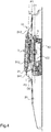
Fig. 4 ] lafigure 4 est une vue en coupe brisée selon le plan A-A de lafigure 3 représentant le dispositif de liaison et la porte dans une position d'obturation d'une ouverture de l'appareil lave-linge ; - [
Fig. 5 ] lafigure 5 est une vue en coupe de la porte de l'appareil lave-linge en position d'obturation ; et - [
Fig. 6 ] lafigure 6 est une vue de détail, en coupe, du dispositif de liaison et de la porte en cours de fermeture. - La
figure 1 représente un appareil lave-linge 1 à chargement frontal ou appareil électroménager 1 selon un mode de réalisation conforme à l'invention. - L'appareil lave-linge 1 comporte une carrosserie 2 et une porte 3.
- La carrosserie 2 constitue une enveloppe externe d'une cuve de lavage.
- La carrosserie 2 présente une forme sensiblement parallélépipédique. La carrosserie comporte des parois externes, et en particulier une paroi externe 20 frontale.
- La paroi externe 20 comprend un bord inférieur 201, un bord supérieur 202 et deux bords latéraux 203, 204. La paroi externe 20 s'étend ici dans un premier plan P1. Le premier plan P1 est sensiblement vertical. Dans le mode de réalisation illustré, la paroi externe 20 est légèrement bombée.
- La paroi externe 20 comprend une ouverture 21, visible notamment à la
figure 2 . L'ouverture 21 est ici circulaire. - L'ouverture 21 donne accès à un dormant 22 et à un tambour 23 dans lequel est traité du linge.
- Le dormant 22 est formée en amont du tambour 23. Le dormant 22 de la carrosserie 2 est ici annulaire. Le tambour 23 présente une forme cylindrique et comprend un bord annulaire 231 formant l'entrée du tambour 23. Le dormant 22 et le bord annulaire 231 du tambour 23 présentent sensiblement le même diamètre.
- La carrosserie 2 comporte sur la paroi externe 20 une pièce 24, bien visible à la
figure 3 . La pièce 24 est formée à la périphérie de l'ouverture 21, c'est-à-dire à proximité de l'ouverture. La pièce 24 est ici formée autour de l'ouverture 21. La pièce 24 est proéminente de la paroi externe 20. Dans le mode de réalisation illustré, la pièce 24 présente une épaisseur variable selon les parties. En d'autres termes, la pièce 24 comprend au moins une première partie 241 ou partie épaisse présentant une épaisseur maximale et au moins une deuxième partie 242 ou partie mince présentant une épaisseur minimale. L'épaisseur de la pièce d'épaisseur variable varie ici linéairement entre la première partie 241 et la deuxième partie 242. - On entend par épaisseur la dimension de la pièce selon une direction perpendiculaire au premier plan P1. L'épaisseur est mesurée à partir de la paroi externe 20. On entend par épaisseur maximale la plus grande épaisseur formée dans la pièce 24 et par épaisseur minimale la plus petite épaisseur formée dans la pièce 24. La première partie présente une épaisseur plus importante que l'épaisseur de la deuxième partie.
- Dans cet exemple de réalisation, la pièce 24 s'étend dans un deuxième plan P2. On définit le deuxième plan P2 comme étant un plan tangent à la pièce 24. Le deuxième plan P2 est ici tangent à la partie épaisse et à la partie mince de la pièce 24. Le deuxième plan P2 est incliné par rapport au premier plan P1 vertical. En d'autres termes, le premier plan P1 et le deuxième plan P2 sont sécants. Le premier plan P1 est incliné par rapport au deuxième plan P2 selon un angle dit deuxième angle α.
- La première partie 241 ou partie épaisse de la pièce 24 est ici formée dans une partie inférieure de l'ouverture 21. La deuxième partie 242 ou partie mince est ici formée dans une partie supérieure de l'ouverture 21.
- La pièce 24 forme ici un cadre autour de l'ouverture 21. La pièce 24 est donc une pièce continue. La pièce 24 présente une forme annulaire. L'ouverture 21 et la pièce 24 présentent sensiblement le même diamètre. En particulier, la pièce 24 présente un même diamètre interne qu'un diamètre de l'ouverture 21.
- Bien entendu, la pièce 24 peut présenter des formes et dimensions différentes et peut être disposée autrement. Dans un autre mode de réalisation, la pièce 24 peut ne pas entourer complètement l'ouverture 21. La pièce 24 disposée uniquement au niveau d'une partie de la périphérie de l'ouverture peut soit présenter une épaisseur variable soit une épaisseur constante. Ou encore, dans un autre mode de réalisation, la pièce 24 peut être discontinue, par exemple sous forme de deux pièces disjointes ayant chacune une épaisseur différente.
- La porte 3 présente la forme d'un hublot comportant un verre 31 transparent et un cadre 32.
- Le cadre 32 présente une forme annulaire et comporte une face externe 321 et une face interne 322.
- Le verre 31 est solidarisé au cadre 32 au niveau du pourtour de la face interne 322. Le verre 31 présente la forme d'une cuvette rentrante en direction de l'intérieur du tambour 23 lorsque la porte 3 est fermée. Le verre 31 comprend un bord arrondi inférieur 311 et une portion incurvée 312. La porte 3 prend une position fermée lorsque l'ouverture 21 est obturée.
- L'appareil lave-linge 1 comporte un joint couramment appelé manchette 4, disposé à l'entrée du tambour 23. La manchette 4 présente une forme sensiblement annulaire. La manchette 4 est réalisée en matière flexible.
- La manchette 4 est dimensionnée de sorte à épouser le bord annulaire 231 du tambour 23. La manchette 4 est également dimensionnée pour épouser la forme du bord inférieur arrondi 311 lorsque la porte 3 est fermée. Lorsque la porte 3 est fermée, le bord arrondi inférieur 311 est en appui contre la manchette 4. La manchette 4 est configurée pour assurer l'étanchéité de l'appareil lave-linge.
- L'appareil lave-linge 1 comporte un dispositif de liaison 5 permettant de relier la carrosserie 2 à la porte 3.
- Dans l'exemple de réalisation décrit et comme visible aux
figures 4 et5 , le dispositif de liaison 5 comporte un premier support de fixation 51 fixé à la porte 3, un deuxième support de fixation 52 fixé à la carrosserie 2 et une pièce centrale 53 reliant le premier support de fixation 51 au deuxième support de fixation 52. - Le premier support de fixation 51 est fixé au cadre 32 de la porte 3. Le premier support de fixation 51 est ici fixé à la face interne 322. La fixation du premier support de fixation 51 au cadre 32 est réalisée par tout moyen déjà connu dans l'art antérieur, par exemple au moyen de vis.
- Le premier support de fixation 51 comprend un premier orifice avant 511.
- Le deuxième support de fixation 52 est fixé à la carrosserie 2. Le deuxième support de fixation 52 est ici fixé au dormant 22. De même que pour le premier support de fixation 51, la fixation du deuxième support de fixation 52 à la carrosserie est réalisée par tout moyen classiquement utilisé et connu dans l'art antérieur.
- Le deuxième support de fixation 52 comprend un premier orifice arrière 521.
- La partie centrale 53 présente ici une forme en C. La partie centrale 53 comprend un deuxième orifice avant 531 et un deuxième orifice arrière 532. Les deuxièmes orifices avant 531 et arrière 532 sont ici formés de part et d'autre de la partie centrale.
- La partie centrale 53 est assemblée d'une part au premier support de fixation 51 de sorte à ce que le premier orifice avant 511 du premier support de fixation 51 soit disposé en regard du deuxième orifice avant 531 de la partie centrale 53. Et d'autre part, la partie centrale 53 est assemblée au deuxième support de fixation 52 de sorte à ce que le premier orifice arrière 521 du deuxième support de fixation 52 soit disposé en regard du deuxième orifice arrière 532 de la partie centrale 53.
- Les premier et deuxième orifices avant 511, 531 du premier support de fixation 51 et de la partie centrale 53 sont configurés pour recevoir un axe pivot avant, également appelé premier axe ou axe avant 512. Les premier et deuxième orifices arrière 521, 532 du deuxième support de fixation 52 et de la partie centrale 53 sont configurés pour recevoir un axe pivot arrière, également appelé deuxième axe ou axe arrière 522.
- Le dispositif de liaison 5 ainsi constitué est une charnière à deux axes pivots, l'axe avant 512 et l'axe arrière 522. Le premier support de fixation 51 et l'axe avant 512 forment une première liaison pivot. Le deuxième support de fixation 52 et l'axe arrière 522, forment une deuxième liaison pivot.
- Le dispositif de liaison 5 permet la rotation de la porte 3 par rapport à la carrosserie 2. Lors de l'ouverture et la fermeture de la porte 3, la partie centrale 53 se déplace suivant un plan horizontal. Dans cet exemple de réalisation, le dormant 22 comprend une cavité 221. La cavité 221 permet le passage de la partie centrale 53. Avantageusement, la cavité 221 présente des dimensions au moins égales à celles de la partie centrale 53 afin de permettre son passage et sa rotation.
- Le dispositif de liaison 5 permet la rotation de la porte 3 entre la position fermée ou position d'obturation et une position d'ouverture maximale. On entend par position d'ouverture maximale la position dans laquelle la partie centrale 53 ne peut plus se déplacer horizontalement.
- Dans cet exemple de réalisation, la porte 3 peut pivoter jusqu'à 55° selon l'axe avant 512. En d'autres termes, la porte 3 peut pivoter de 55° par rapport à la partie centrale 53. La partie centrale 53 peut pivoter jusqu'à 70° selon l'axe arrière 522. En d'autres termes, la partie centrale 53 peut pivoter de 70° par rapport à la carrosserie 2. En d'autres termes, la porte 3 peut pivoter de 125° par rapport à la carrosserie 2.
- Comme cela est visible à la
figure 3 , l'axe arrière 522 s'étend suivant une première direction D1 verticale et l'axe avant 512 s'étend suivant une deuxième direction D2 inclinée. La deuxième direction D2 est inclinée vers la partie mince présentant la plus petite épaisseur de la pièce 24. La deuxième direction D2 est ici inclinée vers la partie supérieure 242 de la pièce 24. Lorsque la porte est en position fermée, la deuxième direction D2 s'étend dans un plan vertical perpendiculaire au premier plan P1. - La première direction de l'axe arrière 522 et la deuxième direction D2 de l'axe avant 512 forment un angle dit premier angle β. Le premier angle β est non nul. Le premier angle β est au moins égal au deuxième angle α formé par le premier plan P1 et le deuxième plan P2.
- La deuxième direction D2 est ici parallèle au deuxième plan P2. Le premier angle β est dans ce mode de réalisation égal au deuxième angle α.
- Le premier angle β et le deuxième angle α sont compris entre 1° et 5°. De préférence, le premier angle β et le deuxième angle α sont égaux à 2,5°.
- Le dispositif ainsi constitué permet la fermeture totale de la porte 3 et ainsi la parfaite obturation de l'ouverture 21. En effet, le premier angle β étant supérieur ou égal au deuxième angle α et l'axe avant étant incliné vers la partie mince de la pièce 24, la fermeture de la porte n'est pas gênée par la présence de la pièce 24 d'épaisseur variable.
- L'inclinaison de l'axe avant 512 suivant le premier angle β supérieur ou égal au deuxième angle α permet de compenser l'inclinaison de la pièce 24. De plus, cela permet un appui plan vertical de la porte 3 contre la manchette 4. En particulier, le bord arrondi inférieur 311 est en appui contre la manchette 4. Une obturation étanche de l'ouverture 21 est ainsi assurée. L'obturation étanche de l'ouverture 21 est particulièrement importante pour les appareils électroménagers tels que les lave-linge impliquant l'utilisation d'eau pouvant générer des fuites.
- Bien entendu, la présente invention n'est pas limitée au mode de réalisation décrit ci-avant. En particulier, la pièce proéminente a été décrite comme ayant une épaisseur variable. La pièce proéminente peut en effet présenter une épaisseur constante et être formée uniquement au niveau d'une partie de la périphérie de l'ouverture. Dans un tel exemple de réalisation, le deuxième angle α est formé entre un plan tangent à la pièce proéminente et incliné vers la paroi externe. Le premier angle β formé par les première et deuxième directions est supérieur ou égal au deuxième angle α. L'axe avant est incliné de telle façon à permettre la fermeture de la porte. La porte n'est en effet plus gênée par la pièce proéminente.
- A titre d'exemple non limitatif, la pièce proéminente d'épaisseur constante peut être formée dans la partie inférieure de l'ouverture. Dans ce cas, la deuxième direction D2 et le deuxième plan P2 présentent tous les deux une inclinaison de la pièce proéminente vers la partie supérieure de l'ouverture.
- La présente description a été faite pour un appareil lave-linge. Bien entendu, cette description reste valable pour tout appareil comportant une carrosserie et une porte devant être reliés entre elles. En particulier, la description est valable pour tout appareil destiné à traiter le linge tel qu'un appareil sèche-linge ou un appareil lave-linge séchant.
Claims (10)
- Appareil électroménager (1) comportant une carrosserie (2), une porte (3) et un dispositif de liaison (5) reliant ladite porte (3) à ladite carrosserie (2), ladite carrosserie (2) comprenant une paroi externe (20) s'étendant dans un premier plan (P1) vertical et dans laquelle est formée une ouverture (21), le dispositif de liaison (5) étant fixé à la porte (3) par une première liaison pivot autour d'un premier axe dit axe avant (512) et à la carrosserie (2) par une deuxième liaison pivot autour d'un deuxième axe dit axe arrière (522), ladite porte (3) étant configurée pour pivoter par rapport à la carrosserie (2) entre une position fermée dans laquelle l'ouverture (21) est obturée et une position d'ouverture maximale, l'appareil électroménager (1) étant caractérisé en ce que ledit axe arrière (522) s'étend suivant une première direction (D1) verticale et ledit axe avant (512) s'étend suivant une deuxième direction (D2) inclinée non parallèle à ladite première direction (D1), ladite première direction (D1) et ladite deuxième direction (D2) formant entre elles un premier angle (β) non nul.
- Appareil électroménager (1) selon la revendication 1, dans lequel lorsque la porte est en position fermée, la deuxième direction (D2) s'étend dans un plan vertical perpendiculaire au premier plan (P1).
- Appareil électroménager (1) selon l'une des revendications 1 ou 2, dans lequel la carrosserie (2) comporte une pièce (24) proéminente disposée à la périphérie de l'ouverture (21).
- Appareil électroménager (1) selon la revendication 3, dans lequel le premier angle (β) est supérieur ou égal à un deuxième angle (α) formé par l'intersection du premier plan (P1) et d'un deuxième plan (P2) tangent à la pièce (24).
- Appareil électroménager (1) selon la revendication 4, dans lequel le premier angle (β) et le deuxième angle (α) sont compris entre 1° et 5°, et de préférence égaux à 2,5°.
- Appareil électroménager (1) selon l'une des revendications 3 à 5, dans lequel la pièce (24) forme un cadre continu sur toute la périphérie de l'ouverture (21).
- Appareil électroménager (1) selon l'une des revendications 3 à 5, dans lequel la pièce (24) est disposée uniquement sur une partie de la périphérie de l'ouverture (21).
- Appareil électroménager (1) selon l'une des revendications 3 à 7, dans lequel la pièce (24) présente une épaisseur variable et comporte une première partie (241) présentant une épaisseur maximale et une deuxième partie (242) présentant une épaisseur minimale.
- Appareil électroménager (1) selon la revendication 8, dans lequel la première partie (241) est formée dans une partie inférieure de l'ouverture (21) et la deuxième partie (242) est formée dans une partie supérieure de l'ouverture (21), et en ce que lorsque la porte (3) est en position fermée, la deuxième direction (D2) est parallèle à un deuxième plan (P2) tangent à la première partie (241) et à la deuxième partie (242) de la pièce (24).
- Appareil électroménager (1) selon l'une des revendications précédentes, dans lequel l'appareil électroménager (1) est un appareil lave-linge.
Applications Claiming Priority (1)
| Application Number | Priority Date | Filing Date | Title |
|---|---|---|---|
| FR1871534A FR3088654B1 (fr) | 2018-11-15 | 2018-11-15 | Appareil electromenager comportant une carrosserie, une porte et un dispositif de liaison reliant la porte a la carrosserie |
Publications (2)
| Publication Number | Publication Date |
|---|---|
| EP3653780A1 true EP3653780A1 (fr) | 2020-05-20 |
| EP3653780B1 EP3653780B1 (fr) | 2022-12-21 |
Family
ID=66041576
Family Applications (1)
| Application Number | Title | Priority Date | Filing Date |
|---|---|---|---|
| EP19208762.5A Active EP3653780B1 (fr) | 2018-11-15 | 2019-11-13 | Appareil électroménager comportant une carrosserie, une porte et un dispositif de liaison reliant la porte à la carrosserie |
Country Status (3)
| Country | Link |
|---|---|
| EP (1) | EP3653780B1 (fr) |
| ES (1) | ES2939746T3 (fr) |
| FR (1) | FR3088654B1 (fr) |
Citations (2)
| Publication number | Priority date | Publication date | Assignee | Title |
|---|---|---|---|---|
| EP0859079A1 (fr) * | 1997-02-17 | 1998-08-19 | CANDY S.p.A. | Charnière pour une porte d'un appareil électroménager, en particulier pour machine à laver ou séchoir à linge |
| EP3124669A1 (fr) | 2014-03-28 | 2017-02-01 | Samsung Electronics Co., Ltd. | Machine à laver à tambour |
-
2018
- 2018-11-15 FR FR1871534A patent/FR3088654B1/fr not_active Expired - Fee Related
-
2019
- 2019-11-13 ES ES19208762T patent/ES2939746T3/es active Active
- 2019-11-13 EP EP19208762.5A patent/EP3653780B1/fr active Active
Patent Citations (2)
| Publication number | Priority date | Publication date | Assignee | Title |
|---|---|---|---|---|
| EP0859079A1 (fr) * | 1997-02-17 | 1998-08-19 | CANDY S.p.A. | Charnière pour une porte d'un appareil électroménager, en particulier pour machine à laver ou séchoir à linge |
| EP3124669A1 (fr) | 2014-03-28 | 2017-02-01 | Samsung Electronics Co., Ltd. | Machine à laver à tambour |
Also Published As
| Publication number | Publication date |
|---|---|
| EP3653780B1 (fr) | 2022-12-21 |
| ES2939746T3 (es) | 2023-04-26 |
| FR3088654A1 (fr) | 2020-05-22 |
| FR3088654B1 (fr) | 2021-03-05 |
Similar Documents
| Publication | Publication Date | Title |
|---|---|---|
| WO1994025802A1 (fr) | Porte de four | |
| FR3067576A1 (fr) | Boitier pour produit cosmetique | |
| FR2521182A3 (fr) | Machine a laver le linge integrable dans un ensemble de meubles | |
| FR3012586A1 (fr) | Systeme de maintien d'au moins un panneau solaire sur un module solaire et module solaire le comportant | |
| FR2966424A1 (fr) | Panneau d'aeronef comprenant une ouverture equipee d'un encadrement | |
| CH636271A5 (fr) | Dispositif pour regler le debit d'un liquide dans un tuyau. | |
| EP3653780B1 (fr) | Appareil électroménager comportant une carrosserie, une porte et un dispositif de liaison reliant la porte à la carrosserie | |
| FR2563098A1 (fr) | Paroi de baignoire pivotable et relevable au-dessus de la robinetterie | |
| EP1071182B1 (fr) | Boîtier d'isolation pour appareil à rapporter sur le socle d'une goulotte par l'intermédiaire d'un support | |
| FR2954794A1 (fr) | Dispositif d'obturation et ensemble correspondant | |
| EP0925742A1 (fr) | Meuble sous évier dépliable | |
| FR2585799A1 (fr) | Joint d'etancheite multifonction notamment pour portiere d'automobile et garniture de baie de portiere automobile constituee de ce joint | |
| FR2938500A1 (fr) | Structure de panneau ouvrant, notamment pour pont de bateau, pont de bateau et bateau correspondants | |
| FR2883910A1 (fr) | Porte, fenetre, ou analogue, a chassis de type battant, comportant un joint d'etancheite centrale tournant | |
| FR2993304A1 (fr) | Dispositif de montage d'un panneau vitre dans une menuiserie | |
| FR2818684A3 (fr) | Organe couvre-charniere pour appareil electromenager | |
| WO1993010699A1 (fr) | Panneau pare-douche en coquille | |
| FR2705138A1 (fr) | Four à porte relevable. | |
| FR2967443A1 (fr) | Huisserie pour porte ou fenetre composee de deux plaques de platre | |
| EP0094437A1 (fr) | Panneau ouvrant, notamment toit ouvrant pour véhicule automobile, entièrement réglable | |
| FR3115759A1 (fr) | Fenêtre vitrée pour navire équipée d’une ouverture se fermant à l’aide d’un panneau vitré basculant. | |
| EP3581437A1 (fr) | Procede de fabrication d'une porte de vehicule | |
| FR2582715A1 (fr) | Lame profilee pour fermeture a rideau et rideau resultant de l'assemblage de telles lames | |
| FR2955351A1 (fr) | Porte a portillon a.p.d. | |
| FR2770574A1 (fr) | Dispositif d'etancheite pour chassis a frappe a ouvrant a deux vantaux |
Legal Events
| Date | Code | Title | Description |
|---|---|---|---|
| PUAI | Public reference made under article 153(3) epc to a published international application that has entered the european phase |
Free format text: ORIGINAL CODE: 0009012 |
|
| STAA | Information on the status of an ep patent application or granted ep patent |
Free format text: STATUS: THE APPLICATION HAS BEEN PUBLISHED |
|
| AK | Designated contracting states |
Kind code of ref document: A1 Designated state(s): AL AT BE BG CH CY CZ DE DK EE ES FI FR GB GR HR HU IE IS IT LI LT LU LV MC MK MT NL NO PL PT RO RS SE SI SK SM TR |
|
| AX | Request for extension of the european patent |
Extension state: BA ME |
|
| STAA | Information on the status of an ep patent application or granted ep patent |
Free format text: STATUS: REQUEST FOR EXAMINATION WAS MADE |
|
| 17P | Request for examination filed |
Effective date: 20200924 |
|
| RBV | Designated contracting states (corrected) |
Designated state(s): AL AT BE BG CH CY CZ DE DK EE ES FI FR GB GR HR HU IE IS IT LI LT LU LV MC MK MT NL NO PL PT RO RS SE SI SK SM TR |
|
| REG | Reference to a national code |
Ref country code: DE Ref legal event code: R079 Ref document number: 602019023348 Country of ref document: DE Free format text: PREVIOUS MAIN CLASS: D06F0039140000 Ipc: E05D0003100000 |
|
| GRAP | Despatch of communication of intention to grant a patent |
Free format text: ORIGINAL CODE: EPIDOSNIGR1 |
|
| STAA | Information on the status of an ep patent application or granted ep patent |
Free format text: STATUS: GRANT OF PATENT IS INTENDED |
|
| RIC1 | Information provided on ipc code assigned before grant |
Ipc: D06F 39/14 20060101ALI20220607BHEP Ipc: E05D 3/10 20060101AFI20220607BHEP |
|
| INTG | Intention to grant announced |
Effective date: 20220624 |
|
| GRAS | Grant fee paid |
Free format text: ORIGINAL CODE: EPIDOSNIGR3 |
|
| GRAA | (expected) grant |
Free format text: ORIGINAL CODE: 0009210 |
|
| STAA | Information on the status of an ep patent application or granted ep patent |
Free format text: STATUS: THE PATENT HAS BEEN GRANTED |
|
| AK | Designated contracting states |
Kind code of ref document: B1 Designated state(s): AL AT BE BG CH CY CZ DE DK EE ES FI FR GB GR HR HU IE IS IT LI LT LU LV MC MK MT NL NO PL PT RO RS SE SI SK SM TR |
|
| REG | Reference to a national code |
Ref country code: GB Ref legal event code: FG4D Free format text: NOT ENGLISH |
|
| REG | Reference to a national code |
Ref country code: CH Ref legal event code: EP |
|
| REG | Reference to a national code |
Ref country code: DE Ref legal event code: R096 Ref document number: 602019023348 Country of ref document: DE |
|
| REG | Reference to a national code |
Ref country code: AT Ref legal event code: REF Ref document number: 1539148 Country of ref document: AT Kind code of ref document: T Effective date: 20230115 |
|
| REG | Reference to a national code |
Ref country code: IE Ref legal event code: FG4D Free format text: LANGUAGE OF EP DOCUMENT: FRENCH |
|
| REG | Reference to a national code |
Ref country code: LT Ref legal event code: MG9D |
|
| REG | Reference to a national code |
Ref country code: NL Ref legal event code: MP Effective date: 20221221 Ref country code: ES Ref legal event code: FG2A Ref document number: 2939746 Country of ref document: ES Kind code of ref document: T3 Effective date: 20230426 |
|
| PG25 | Lapsed in a contracting state [announced via postgrant information from national office to epo] |
Ref country code: SE Free format text: LAPSE BECAUSE OF FAILURE TO SUBMIT A TRANSLATION OF THE DESCRIPTION OR TO PAY THE FEE WITHIN THE PRESCRIBED TIME-LIMIT Effective date: 20221221 Ref country code: NO Free format text: LAPSE BECAUSE OF FAILURE TO SUBMIT A TRANSLATION OF THE DESCRIPTION OR TO PAY THE FEE WITHIN THE PRESCRIBED TIME-LIMIT Effective date: 20230321 Ref country code: LT Free format text: LAPSE BECAUSE OF FAILURE TO SUBMIT A TRANSLATION OF THE DESCRIPTION OR TO PAY THE FEE WITHIN THE PRESCRIBED TIME-LIMIT Effective date: 20221221 Ref country code: FI Free format text: LAPSE BECAUSE OF FAILURE TO SUBMIT A TRANSLATION OF THE DESCRIPTION OR TO PAY THE FEE WITHIN THE PRESCRIBED TIME-LIMIT Effective date: 20221221 |
|
| REG | Reference to a national code |
Ref country code: AT Ref legal event code: MK05 Ref document number: 1539148 Country of ref document: AT Kind code of ref document: T Effective date: 20221221 |
|
| PG25 | Lapsed in a contracting state [announced via postgrant information from national office to epo] |
Ref country code: RS Free format text: LAPSE BECAUSE OF FAILURE TO SUBMIT A TRANSLATION OF THE DESCRIPTION OR TO PAY THE FEE WITHIN THE PRESCRIBED TIME-LIMIT Effective date: 20221221 Ref country code: LV Free format text: LAPSE BECAUSE OF FAILURE TO SUBMIT A TRANSLATION OF THE DESCRIPTION OR TO PAY THE FEE WITHIN THE PRESCRIBED TIME-LIMIT Effective date: 20221221 Ref country code: HR Free format text: LAPSE BECAUSE OF FAILURE TO SUBMIT A TRANSLATION OF THE DESCRIPTION OR TO PAY THE FEE WITHIN THE PRESCRIBED TIME-LIMIT Effective date: 20221221 Ref country code: GR Free format text: LAPSE BECAUSE OF FAILURE TO SUBMIT A TRANSLATION OF THE DESCRIPTION OR TO PAY THE FEE WITHIN THE PRESCRIBED TIME-LIMIT Effective date: 20230322 |
|
| PG25 | Lapsed in a contracting state [announced via postgrant information from national office to epo] |
Ref country code: NL Free format text: LAPSE BECAUSE OF FAILURE TO SUBMIT A TRANSLATION OF THE DESCRIPTION OR TO PAY THE FEE WITHIN THE PRESCRIBED TIME-LIMIT Effective date: 20221221 |
|
| PG25 | Lapsed in a contracting state [announced via postgrant information from national office to epo] |
Ref country code: SM Free format text: LAPSE BECAUSE OF FAILURE TO SUBMIT A TRANSLATION OF THE DESCRIPTION OR TO PAY THE FEE WITHIN THE PRESCRIBED TIME-LIMIT Effective date: 20221221 Ref country code: RO Free format text: LAPSE BECAUSE OF FAILURE TO SUBMIT A TRANSLATION OF THE DESCRIPTION OR TO PAY THE FEE WITHIN THE PRESCRIBED TIME-LIMIT Effective date: 20221221 Ref country code: PT Free format text: LAPSE BECAUSE OF FAILURE TO SUBMIT A TRANSLATION OF THE DESCRIPTION OR TO PAY THE FEE WITHIN THE PRESCRIBED TIME-LIMIT Effective date: 20230421 Ref country code: EE Free format text: LAPSE BECAUSE OF FAILURE TO SUBMIT A TRANSLATION OF THE DESCRIPTION OR TO PAY THE FEE WITHIN THE PRESCRIBED TIME-LIMIT Effective date: 20221221 Ref country code: CZ Free format text: LAPSE BECAUSE OF FAILURE TO SUBMIT A TRANSLATION OF THE DESCRIPTION OR TO PAY THE FEE WITHIN THE PRESCRIBED TIME-LIMIT Effective date: 20221221 Ref country code: AT Free format text: LAPSE BECAUSE OF FAILURE TO SUBMIT A TRANSLATION OF THE DESCRIPTION OR TO PAY THE FEE WITHIN THE PRESCRIBED TIME-LIMIT Effective date: 20221221 |
|
| PG25 | Lapsed in a contracting state [announced via postgrant information from national office to epo] |
Ref country code: SK Free format text: LAPSE BECAUSE OF FAILURE TO SUBMIT A TRANSLATION OF THE DESCRIPTION OR TO PAY THE FEE WITHIN THE PRESCRIBED TIME-LIMIT Effective date: 20221221 Ref country code: PL Free format text: LAPSE BECAUSE OF FAILURE TO SUBMIT A TRANSLATION OF THE DESCRIPTION OR TO PAY THE FEE WITHIN THE PRESCRIBED TIME-LIMIT Effective date: 20221221 Ref country code: IS Free format text: LAPSE BECAUSE OF FAILURE TO SUBMIT A TRANSLATION OF THE DESCRIPTION OR TO PAY THE FEE WITHIN THE PRESCRIBED TIME-LIMIT Effective date: 20230421 Ref country code: AL Free format text: LAPSE BECAUSE OF FAILURE TO SUBMIT A TRANSLATION OF THE DESCRIPTION OR TO PAY THE FEE WITHIN THE PRESCRIBED TIME-LIMIT Effective date: 20221221 |
|
| REG | Reference to a national code |
Ref country code: DE Ref legal event code: R097 Ref document number: 602019023348 Country of ref document: DE |
|
| PLBE | No opposition filed within time limit |
Free format text: ORIGINAL CODE: 0009261 |
|
| STAA | Information on the status of an ep patent application or granted ep patent |
Free format text: STATUS: NO OPPOSITION FILED WITHIN TIME LIMIT |
|
| PG25 | Lapsed in a contracting state [announced via postgrant information from national office to epo] |
Ref country code: DK Free format text: LAPSE BECAUSE OF FAILURE TO SUBMIT A TRANSLATION OF THE DESCRIPTION OR TO PAY THE FEE WITHIN THE PRESCRIBED TIME-LIMIT Effective date: 20221221 |
|
| 26N | No opposition filed |
Effective date: 20230922 |
|
| PG25 | Lapsed in a contracting state [announced via postgrant information from national office to epo] |
Ref country code: SI Free format text: LAPSE BECAUSE OF FAILURE TO SUBMIT A TRANSLATION OF THE DESCRIPTION OR TO PAY THE FEE WITHIN THE PRESCRIBED TIME-LIMIT Effective date: 20221221 |
|
| PG25 | Lapsed in a contracting state [announced via postgrant information from national office to epo] |
Ref country code: IT Free format text: LAPSE BECAUSE OF FAILURE TO SUBMIT A TRANSLATION OF THE DESCRIPTION OR TO PAY THE FEE WITHIN THE PRESCRIBED TIME-LIMIT Effective date: 20221221 |
|
| REG | Reference to a national code |
Ref country code: CH Ref legal event code: PL |
|
| PG25 | Lapsed in a contracting state [announced via postgrant information from national office to epo] |
Ref country code: MC Free format text: LAPSE BECAUSE OF FAILURE TO SUBMIT A TRANSLATION OF THE DESCRIPTION OR TO PAY THE FEE WITHIN THE PRESCRIBED TIME-LIMIT Effective date: 20221221 |
|
| PG25 | Lapsed in a contracting state [announced via postgrant information from national office to epo] |
Ref country code: LU Free format text: LAPSE BECAUSE OF NON-PAYMENT OF DUE FEES Effective date: 20231113 |
|
| PG25 | Lapsed in a contracting state [announced via postgrant information from national office to epo] |
Ref country code: CH Free format text: LAPSE BECAUSE OF NON-PAYMENT OF DUE FEES Effective date: 20231130 |
|
| GBPC | Gb: european patent ceased through non-payment of renewal fee |
Effective date: 20231113 |
|
| PG25 | Lapsed in a contracting state [announced via postgrant information from national office to epo] |
Ref country code: MC Free format text: LAPSE BECAUSE OF FAILURE TO SUBMIT A TRANSLATION OF THE DESCRIPTION OR TO PAY THE FEE WITHIN THE PRESCRIBED TIME-LIMIT Effective date: 20221221 Ref country code: LU Free format text: LAPSE BECAUSE OF NON-PAYMENT OF DUE FEES Effective date: 20231113 Ref country code: CH Free format text: LAPSE BECAUSE OF NON-PAYMENT OF DUE FEES Effective date: 20231130 |
|
| REG | Reference to a national code |
Ref country code: BE Ref legal event code: MM Effective date: 20231130 |
|
| REG | Reference to a national code |
Ref country code: IE Ref legal event code: MM4A |
|
| PG25 | Lapsed in a contracting state [announced via postgrant information from national office to epo] |
Ref country code: IE Free format text: LAPSE BECAUSE OF NON-PAYMENT OF DUE FEES Effective date: 20231113 |
|
| PG25 | Lapsed in a contracting state [announced via postgrant information from national office to epo] |
Ref country code: GB Free format text: LAPSE BECAUSE OF NON-PAYMENT OF DUE FEES Effective date: 20231113 |
|
| PG25 | Lapsed in a contracting state [announced via postgrant information from national office to epo] |
Ref country code: BE Free format text: LAPSE BECAUSE OF NON-PAYMENT OF DUE FEES Effective date: 20231130 |
|
| PG25 | Lapsed in a contracting state [announced via postgrant information from national office to epo] |
Ref country code: IE Free format text: LAPSE BECAUSE OF NON-PAYMENT OF DUE FEES Effective date: 20231113 Ref country code: GB Free format text: LAPSE BECAUSE OF NON-PAYMENT OF DUE FEES Effective date: 20231113 Ref country code: BE Free format text: LAPSE BECAUSE OF NON-PAYMENT OF DUE FEES Effective date: 20231130 |
|
| PG25 | Lapsed in a contracting state [announced via postgrant information from national office to epo] |
Ref country code: BG Free format text: LAPSE BECAUSE OF FAILURE TO SUBMIT A TRANSLATION OF THE DESCRIPTION OR TO PAY THE FEE WITHIN THE PRESCRIBED TIME-LIMIT Effective date: 20221221 |
|
| PG25 | Lapsed in a contracting state [announced via postgrant information from national office to epo] |
Ref country code: BG Free format text: LAPSE BECAUSE OF FAILURE TO SUBMIT A TRANSLATION OF THE DESCRIPTION OR TO PAY THE FEE WITHIN THE PRESCRIBED TIME-LIMIT Effective date: 20221221 |
|
| PG25 | Lapsed in a contracting state [announced via postgrant information from national office to epo] |
Ref country code: CY Free format text: LAPSE BECAUSE OF FAILURE TO SUBMIT A TRANSLATION OF THE DESCRIPTION OR TO PAY THE FEE WITHIN THE PRESCRIBED TIME-LIMIT; INVALID AB INITIO Effective date: 20191113 |
|
| PG25 | Lapsed in a contracting state [announced via postgrant information from national office to epo] |
Ref country code: HU Free format text: LAPSE BECAUSE OF FAILURE TO SUBMIT A TRANSLATION OF THE DESCRIPTION OR TO PAY THE FEE WITHIN THE PRESCRIBED TIME-LIMIT; INVALID AB INITIO Effective date: 20191113 |
|
| PG25 | Lapsed in a contracting state [announced via postgrant information from national office to epo] |
Ref country code: TR Free format text: LAPSE BECAUSE OF FAILURE TO SUBMIT A TRANSLATION OF THE DESCRIPTION OR TO PAY THE FEE WITHIN THE PRESCRIBED TIME-LIMIT Effective date: 20221221 |
|
| PGFP | Annual fee paid to national office [announced via postgrant information from national office to epo] |
Ref country code: DE Payment date: 20251117 Year of fee payment: 7 |
|
| PGFP | Annual fee paid to national office [announced via postgrant information from national office to epo] |
Ref country code: FR Payment date: 20251127 Year of fee payment: 7 |
|
| PGFP | Annual fee paid to national office [announced via postgrant information from national office to epo] |
Ref country code: ES Payment date: 20251210 Year of fee payment: 7 |