EP3653977B1 - Kühlschrank - Google Patents
Kühlschrank Download PDFInfo
- Publication number
- EP3653977B1 EP3653977B1 EP18849569.1A EP18849569A EP3653977B1 EP 3653977 B1 EP3653977 B1 EP 3653977B1 EP 18849569 A EP18849569 A EP 18849569A EP 3653977 B1 EP3653977 B1 EP 3653977B1
- Authority
- EP
- European Patent Office
- Prior art keywords
- inner door
- coupling
- door
- coupled
- handle
- Prior art date
- Legal status (The legal status is an assumption and is not a legal conclusion. Google has not performed a legal analysis and makes no representation as to the accuracy of the status listed.)
- Active
Links
Images









Classifications
-
- E—FIXED CONSTRUCTIONS
- E05—LOCKS; KEYS; WINDOW OR DOOR FITTINGS; SAFES
- E05B—LOCKS; ACCESSORIES THEREFOR; HANDCUFFS
- E05B1/00—Knobs or handles for wings; Knobs, handles, or press buttons for locks or latches on wings
- E05B1/0015—Knobs or handles which do not operate the bolt or lock, e.g. non-movable; Mounting thereof
-
- E—FIXED CONSTRUCTIONS
- E05—LOCKS; KEYS; WINDOW OR DOOR FITTINGS; SAFES
- E05B—LOCKS; ACCESSORIES THEREFOR; HANDCUFFS
- E05B1/00—Knobs or handles for wings; Knobs, handles, or press buttons for locks or latches on wings
- E05B1/0038—Sliding handles, e.g. push buttons
-
- E—FIXED CONSTRUCTIONS
- E05—LOCKS; KEYS; WINDOW OR DOOR FITTINGS; SAFES
- E05C—BOLTS OR FASTENING DEVICES FOR WINGS, SPECIALLY FOR DOORS OR WINDOWS
- E05C7/00—Fastening devices specially adapted for two wings
- E05C7/02—Fastening devices specially adapted for two wings for wings which lie one behind the other when closed
-
- F—MECHANICAL ENGINEERING; LIGHTING; HEATING; WEAPONS; BLASTING
- F25—REFRIGERATION OR COOLING; COMBINED HEATING AND REFRIGERATION SYSTEMS; HEAT PUMP SYSTEMS; MANUFACTURE OR STORAGE OF ICE; LIQUEFACTION SOLIDIFICATION OF GASES
- F25D—REFRIGERATORS; COLD ROOMS; ICE-BOXES; COOLING OR FREEZING APPARATUS NOT OTHERWISE PROVIDED FOR
- F25D23/00—General constructional features
- F25D23/02—Doors; Covers
- F25D23/028—Details
-
- E—FIXED CONSTRUCTIONS
- E05—LOCKS; KEYS; WINDOW OR DOOR FITTINGS; SAFES
- E05Y—INDEXING SCHEME ASSOCIATED WITH SUBCLASSES E05D AND E05F, RELATING TO CONSTRUCTION ELEMENTS, ELECTRIC CONTROL, POWER SUPPLY, POWER SIGNAL OR TRANSMISSION, USER INTERFACES, MOUNTING OR COUPLING, DETAILS, ACCESSORIES, AUXILIARY OPERATIONS NOT OTHERWISE PROVIDED FOR, APPLICATION THEREOF
- E05Y2900/00—Application of doors, windows, wings or fittings thereof
- E05Y2900/30—Application of doors, windows, wings or fittings thereof for domestic appliances
- E05Y2900/31—Application of doors, windows, wings or fittings thereof for domestic appliances for refrigerators
-
- F—MECHANICAL ENGINEERING; LIGHTING; HEATING; WEAPONS; BLASTING
- F25—REFRIGERATION OR COOLING; COMBINED HEATING AND REFRIGERATION SYSTEMS; HEAT PUMP SYSTEMS; MANUFACTURE OR STORAGE OF ICE; LIQUEFACTION SOLIDIFICATION OF GASES
- F25D—REFRIGERATORS; COLD ROOMS; ICE-BOXES; COOLING OR FREEZING APPARATUS NOT OTHERWISE PROVIDED FOR
- F25D2201/00—Insulation
- F25D2201/10—Insulation with respect to heat
- F25D2201/12—Insulation with respect to heat using an insulating packing material
- F25D2201/126—Insulation with respect to heat using an insulating packing material of cellular type
-
- F—MECHANICAL ENGINEERING; LIGHTING; HEATING; WEAPONS; BLASTING
- F25—REFRIGERATION OR COOLING; COMBINED HEATING AND REFRIGERATION SYSTEMS; HEAT PUMP SYSTEMS; MANUFACTURE OR STORAGE OF ICE; LIQUEFACTION SOLIDIFICATION OF GASES
- F25D—REFRIGERATORS; COLD ROOMS; ICE-BOXES; COOLING OR FREEZING APPARATUS NOT OTHERWISE PROVIDED FOR
- F25D23/00—General constructional features
- F25D23/02—Doors; Covers
- F25D23/025—Secondary closures
-
- F—MECHANICAL ENGINEERING; LIGHTING; HEATING; WEAPONS; BLASTING
- F25—REFRIGERATION OR COOLING; COMBINED HEATING AND REFRIGERATION SYSTEMS; HEAT PUMP SYSTEMS; MANUFACTURE OR STORAGE OF ICE; LIQUEFACTION SOLIDIFICATION OF GASES
- F25D—REFRIGERATORS; COLD ROOMS; ICE-BOXES; COOLING OR FREEZING APPARATUS NOT OTHERWISE PROVIDED FOR
- F25D2323/00—General constructional features not provided for in other groups of this subclass
- F25D2323/02—Details of doors or covers not otherwise covered
- F25D2323/021—French doors
-
- F—MECHANICAL ENGINEERING; LIGHTING; HEATING; WEAPONS; BLASTING
- F25—REFRIGERATION OR COOLING; COMBINED HEATING AND REFRIGERATION SYSTEMS; HEAT PUMP SYSTEMS; MANUFACTURE OR STORAGE OF ICE; LIQUEFACTION SOLIDIFICATION OF GASES
- F25D—REFRIGERATORS; COLD ROOMS; ICE-BOXES; COOLING OR FREEZING APPARATUS NOT OTHERWISE PROVIDED FOR
- F25D2323/00—General constructional features not provided for in other groups of this subclass
- F25D2323/02—Details of doors or covers not otherwise covered
- F25D2323/023—Door in door constructions
Definitions
- the present disclosure relates to a refrigerator, and more particularly, to a refrigerator in which the structure of a door is improved.
- a refrigerator is a home appliance capable of keeping foods fresh by providing a storage compartment configured to store the foods and a cold air supply device configured to supply cold air to the storage compartment.
- the refrigerator includes components for a refrigeration cycle therein, and is a device that refrigerates or freezes an object stored in the storage compartment through the cool air generated from the components for the refrigeration cycle.
- the refrigerator may be classified according to the type of storage compartment and type of door.
- top mounted freezer (TMP) type refrigerators in which a storage compartment is divided into an upper portion and a lower portion by a horizontal partition wall to form a freezing compartment at an upper side of the storage compartment and a refrigerating compartment at a lower side thereof
- BMF bottom mounted freezer
- FDR French door type refrigerator
- BMF bottom mounted freezer
- SBS side-by-side
- a storage compartment is divided into left and right sides by a vertical partition wall to form a freezing compartment at one of the left and right sides and a refrigerating compartment chamber at the other side thereof.
- KR 2008 0100622 A discloses a refrigerator having a door frame, a coupling member coupled to the door frame and a door handle coupled with the coupling member in a sliding manner.
- US 8 732 910 B1 discloses a handle assembly for a refrigerator.
- KR 2016 0023741 A discloses a door frame coupling structure.
- the convenience of assembling the door handle may be increased, and the quality of the appearance of the door handle may be improved.
- the door may be easily opened and closed because the user may intuitively distinguish the door handle of the double door.
- the double door may be opened smoothly.
- the insulation of the storage compartment may be efficiently performed because an insulating material may be uniformly filled in an insulating partition wall provided to seal between the upper door and the lower door.
- FIG. 1 is a perspective view of a refrigerator according to an embodiment of the present disclosure.
- FIG. 2 is a view illustrating a state in which a door is opened in the refrigerator according to an embodiment of the present disclosure.
- FIG. 3 is a view illustrating a state in which an outer door is opened in the refrigerator according to an embodiment of the present disclosure.
- a refrigerator 1 includes a main body 10, and a storage compartment 20 formed inside the main body 10.
- the refrigerator 1 includes a door 30 configured to open and close the storage compartment 20, and a cold air supply unit (not shown) configured to supply cold air to the storage compartment 20.
- the main body 10 may include an inner case 12 configured to form the storage compartment 20, and an outer case 11 connected to the outside of the inner case 12 to form an exterior of the main body 10.
- the main body 10 may include insulation (not shown) to be foamed between the inner case 12 and the outer case 11 to insulate the storage compartment 20.
- the cold air supply unit may generate cold air using a cooling cycle that compresses, condenses, expands, and evaporates a refrigerant.
- a front surface of the storage compartment 20 may be provided to be opened, and the storage compartment 20 may be divided into a refrigerating compartment 20a at a right side thereof and a freezing compartment 20b at a left side thereof by a vertical partition wall 14.
- the present disclosure is not limited thereto, and the positions of the refrigerating compartment 20a and the freezing compartment 20b may be variously provided.
- the storage compartment 20 may include a plurality of shelves 15.
- the storage compartment 20 may be opened and closed by the door 30 rotatably coupled to the main body 10.
- the door 30 configured to open and close the storage compartment 20 may be laterally disposed thereat.
- the refrigerating compartment 20a may be opened and closed by a first door 40 rotatably coupled to the main body 10, and the freezing compartment 20b may be opened and closed by a second door 50 rotatably coupled to the main body 10.
- the second door 50 may include an upper door 51 rotatably coupled to the upper portion of the main body 10, and a lower door 52 disposed at the lower portion of the upper door 51.
- the main body 10 may include an insulating partition wall 400 to be coupled with the inner case 12 to be positioned between the upper door 51 and the lower door 52.
- the insulating partition wall 400 may not divide the freezing compartment 20b up and down.
- the insulating partition wall 400 may be formed only partially in the front portion of the inner case 12 to have a surface to which a gasket 63 of the upper door 51 and the lower door 52 may be in close contact.
- a space between a rear end of the insulating partition wall 400 and a rear wall of the freezing compartment 20b may be empty.
- the shelf 15 may be mounted in the empty space between the rear end of the insulating partition wall 400 and the rear wall of the freezing chamber 20b.
- a detailed description of the detailed structure of the insulating partition wall 400 is given below.
- the first door 40 includes an inner door 41 arranged in a double and rotatably coupled to the main body 10, and a second door 50 rotatably coupled to the inner door 41 to cover the inner door 41.
- An outer door 42 may include a first outer door 43 rotatably coupled to an upper portion of the inner door 41 and a second outer door 44 rotatably coupled to a lower portion of the inner door 41 to be disposed at the lower portion of the first outer door 43.
- the door 30 includes a door handle 100 that can be gripped by the user to open and close the door 30.
- the door handle 100 may include a first door handle 110 arranged to grip the first door 40 and a second door handle 120 arranged to grip the second door 50.
- the second door handle 120 may include an upper door handle 121 arranged to grip the upper door 51 and a lower door handle 122 arranged to grip the lower door 52.
- the first door handle 110 includes an inner door handle 111 arranged to grip the inner door 41 and an outer door handle 112 arranged to grip the outer door 42.
- the outer door handle 112 may include a first outer door handle 113 arranged to grip the first outer door 43 and a second outer door handle 114 arranged to grip the second outer door 44.
- a door guard 61 may be provided at a rear surface of each of the first door 30 and the second door 50 to receive foods.
- the door 30 may include a guard supporting portion 62 extending vertically from the door 30 to support the door guard 61 at left and right sides thereof.
- the guard supporting portion 62 may be separably provided at the door 30 as a separate configuration.
- the gasket 63 may be provided at an edge of the rear surface of the door 30 to seal a gap between the main body 10 and the door 30 in a state in which the door 30 is closed.
- the gasket 63 may be installed in a form of a loop along the edge of the rear surface of the door 30, and a magnet (not shown) may be contained in the gasket 63.
- the inner door 41 may include a door opening 64 having an open interior.
- the outer door 42 may be configured to cover the door opening 64 of the inner door 41.
- the refrigerator 1 may include a display 80 having an input and output function.
- the display 80 may be installed at the front surface of the door 30.
- the display 80 may be provided at the first outer door 43.
- a display mounting portion 65 may be formed to be recessed at the front surface of the first door 43 to allow the display 80 to be installed thereon. Since the display 80 is formed in a substantially quadrangular shape, the display mounting portion 65 may also be formed in a quadrangular shape.
- the refrigerator 1 may include an electric wire (not shown) connecting the door 30 to the main body 10 for an electronic device installed at the door 30.
- the electric wire may be connected to the display 80 to transmit information between the display 80 and the controller, or to supply power to the display 80.
- the main body 10 may include a hinge 67.
- the hinge 67 By the hinge 67, the inner door 41 and the outer door 42 can be operated in an open state with respect to the main body 10.
- the outer door 42 can be operated in an open state with respect to the inner door 41 by the hinge 67.
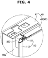
- FIG. 4 is an enlarged view illustrating a portion A in the refrigerator shown in the FIG. 1 .
- FIG. 5 is an enlarged cross-sectional view illustrating a portion A in the refrigerator shown in the FIG. 1 .
- the first door handle 110 includes the inner door handle 111 coupled to an inner door frame 69a provided at the inner door 41 to open the inner door 41 together with the outer door 42.
- the first door handle 110 includes the outer door handle 112 provided at the outer door 42 to only open the outer door 42.
- the first door handle 110 includes a grip portion 140 extending toward the outside of the first door 40 when the first door 40 is closed.
- the inner door handle 111 includes a first grip portion 141 extending toward the outside of the inner door 41 when the inner door 41 is closed.
- the outer door handle 112 includes a second grip portion 142 extending toward the outside of the outer door 42 when the outer door 42 is closed.
- the second grip portion 142 of the outer door handle 112 protrudes more than the first grip portion 141 of the inner door handle 111.
- the second grip portion 142 and the inner door 41 may have the same position in the direction toward the vertical partition wall 14. That is, the second grip portion 142 may have a position corresponding to one side edge of the inner door 41.
- the inner door handle 111 is covered by the outer door handle 112 so as not to be exposed to the outside when viewed from the front of the refrigerator 1.
- the inner door handle 111 includes a first receiving groove 115 to receive a user's hand
- the outer door handle 112 includes a second receiving groove 116 to receive a user's hand.
- the user can open the inner door 41 together with the outer door 42 by putting his or her hand into the first receiving groove 115, approaching the inner door handle 111, and gripping the first grip portion 141.
- the user can open only the outer door 42 by putting his or her hand into the second receiving groove 116, approaching the outer door handle 112, and gripping the second grip portion 142.
- the user can distinguish intuitively the inner door handle 111 and the outer door handle 112 by the depth difference of the finger of the user when the user grasps the first door handle 110.
- the gasket 63 may be disposed between the inner door 41 and the outer door 42 to maintain sealing.
- the refrigerator 1 may include a locking unit 300 to lock the outer door 42 and the inner door 41 and a latch cover 330 provided at the inner door frame 69a to cover the locking unit 300.
- a locking unit 300 to lock the outer door 42 and the inner door 41
- a latch cover 330 provided at the inner door frame 69a to cover the locking unit 300.
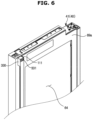
- FIG. 6 is an enlarged perspective view illustrating an inner door in the refrigerator according to an embodiment of the present disclosure.
- FIG. 7 is an exploded view illustrating the inner door in the refrigerator according to an embodiment of the present disclosure.
- the inner door 41 includes the inner door handle 111 coupled to the inner door frame 69a.
- the inner door 41 includes a coupling member 200 coupled to the inner door frame 69a provided at the inner door 41 in a sliding manner and the inner door handle 111 coupled to the coupling member 200 in a sliding manner.
- the user can freely grasp the first grip portion 141 of the inner door handle 111 from the upper portion to the lower portion of the inner door handle 111.
- the inner door frame 69a includes a coupling hole 70 provided at the front surface of the inner door frame 69a to be coupled with the coupling member 200.
- the coupling holes 70 are illustrated as four in FIG. 7 , the number of the coupling holes 70 is not limited thereto, and the number of the coupling holes 70 may be variously provided.
- the coupling member 200 includes a first coupling portion 210 and a second coupling portion 220 extending upward from the first coupling portion 210 and having a smaller length protruding forward than the first coupling portion 210.
- the inner door handle 111 may include a fixing member 160 provided to fix the inner door handle 111 to the coupling member 200 and a fixing hole 170 provided to allow the fixing member 160 to be inserted .
- the movement of the inner door handle 111 in the front-rear direction may be prevented because the inner door handle is inserted from the front to the rear of the inner door 41 and then coupled from the upper portion to the lower portion of the inner door 41 in a sliding manner.
- the fixing member 160 configured to fix the inner door handle 111 to the inner door 41 may be required only to prevent the inner door handle 111 from moving in the vertical direction. Accordingly, the refrigerator 1 according to an embodiment of the present disclosure may reduce the production cost by reducing the number of fixing members 160 configured to fix the inner door handle 111 to the inner door 41.
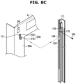
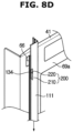
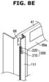
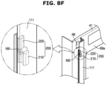
- FIGS. 8A to 8F are a view illustrating a process in which an inner door handle is coupled to an inner door frame in the refrigerator according to an embodiment of the present disclosure.
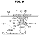
- FIG. 9 is a cross-sectional view illustrating the inner door handle coupled to the inner door frame in the refrigerator according to an embodiment of the present disclosure.
- the inner door frame 69a includes the coupling hole 70 having a first coupling hole 71 provided at the front surface of the inner door frame 69a to be coupled with the coupling member 200 and a second coupling hole 72 extending from the first coupling hole 71 and having a size larger than the first coupling hole 71.
- the coupling member 200 includes a first coupling portion 210 coupled to the first coupling hole 71 and a second coupling portion 220 coupled to the second coupling hole 72 and provided at the upper side of the first coupling portion 210.
- the coupling member 200 may be inserted from the rear to the front of the inner door 41 toward the coupling hole 70 so that the first coupling portion 210 corresponds to the second coupling hole 72.
- the first coupling portion 210 may be inserted directly into the second coupling hole 72 from the rear to the front of the second coupling hole 72, but the first coupling portion 210 may not be inserted directly into the first coupling hole 71 from the rear to the front of the first coupling hole 71.
- the width of a frame engaging portion 202 (see FIG. 9 ) of the engaging member 200 may be smaller than the width of the second coupling hole 72, but larger than the width of the first coupling hole 71.
- the second coupling portion 220 extending from the upper side of the first coupling portion 210 may interfere with the rear surface of the inner door frame 69a, when the first coupling portion 210 is inserted into the second coupling hole 72.
- the coupling member 200 may be inserted into the coupling hole 70 because interference between the coupling member 200 and the inner door frame 69a is reduced by the elasticity of the coupling member 200 and the inner door frame 69a.
- the first coupling portion 210 and the second coupling portion 220 of the coupling member 200 are formed integrally with each other.
- the coupling member 200 may be formed by assembling the first coupling portion 210 and the second coupling portion 220.
- the coupling member 200 inserted into the second coupling hole 72 is coupled to the first coupling hole 71 because the coupling member 200 is slid to the second coupling hole 72 down toward the first coupling hole 71.
- the empty space of the second coupling hole 72, which is covered by the first coupling portion 210, may be covered again by the second coupling portion 220.
- the second coupling hole 72 affects the appearance and it is possible to prevent the insulating material (not shown) from leaking through the second coupling hole 72.
- a supporting portion 201 (see FIG. 9 ) of the coupling member 200 coupled to the inner door frame 69a may be supported by the insulating material (not shown) foamed inside the inner door 41.
- the inner door handle 111 may be coupled to the coupling member 200 from the front to the rear of the inner door 41 so as to be coupled to the coupling member 200.
- the inner door handle 111 may include protruding portions 133 protruding inward of the inner door handle 111 and a receiving groove 134 provided between the protruding portions 133.
- the first coupling portion 210 may include a handle assembling portion 213 (see FIG. 9 ) extending forward from the frame engaging portion 202 and a handle engaging portion 212 (see FIG. 9 ) extending forward from the handle assembling portion 213 .
- the width of the handle engaging portion 212 may be larger than the width of the handle assembling portion 213.
- the width of the handle engaging portion 212 may be larger than the distance between the protruding portions 133 provided to opposite of the inner door handle 111.
- the inner door handle 111 may be coupled to the coupling member 200 from the front to the rear of the inner door 41 at a position where the handle engaging portion 212 of the first coupling portion 210 and the receiving groove 134 correspond to each other.
- the inner door handle 111 when the inner door handle 111 is coupled to the coupling member 200 so that the receiving groove 134 corresponds to the handle engaging portion 212, the inner door handle 111 may be protruded upward than the inner door 41.
- the inner door handle 111 may be fully coupled to the coupling member 200 because the inner door handle protruding upward from the inner door 41 is slid toward the lower side of the inner door 41.
- the inner door handle 111 is not only coupled to the inner door 41 from the front to the rear of the inner door 41, but after the inner door handle 111 is coupled to the inner door 41 from the front to the rear of the inner door 41, the inner door handle 111 is also coupled to the inner door 41 from the upper portion to the lower portion of the inner door 41 in a sliding manner. Therefore, it is possible to prevent the inner door handle 111 from moving in the front-rear direction.
- the inner door handle 111 is not integrally formed, and may be coupled with each other by dividing into a plurality of parts.
- the inner door handle 111 may be coupled with each other by dividing into two.
- the method that the two inner door handles 111 are coupled to the inner door 41 through the coupling member 200 may most be similar to the method that the inner door handle 111 integrally formed is coupled to the inner door 41 through the coupling member 200, however, the two inner door handles 111 may be slidably coupled up and down, respectively.
- one inner door handle 111 may be slidably downwardly coupled to the inner door 41 after inserted from the front to the rear of the inner door 41, and the other inner door handle 111 may be slidably upwardly coupled to the inner door 41 after inserted from the front to the rear of the inner door 41.
- Each of the inner door handles 111 slidably coupled to the upper side and the lower side of the inner door 41 may be fully coupled to the inner door 41 by being coupled to each other.
- the fixing member 160 may be fastened to prevent the inner door handle 111 from being detached downward from the coupling member 200.
- the fixing member 160 may be disposed to be positioned at upper portion of the first coupling portion 210 and in front of the second coupling portion 220 when the inner door handle 111 is coupled to the coupling member 200.
- the fixing member 160 may be in contact with the upper portion of the first coupling portion 210.
- the present disclosure is not limited thereto, and the fixing member 160 may be disposed at various positions as long as that the inner door handle 111 is prevented from being detached from the coupling member 200 downwardly.
- the refrigerator 1 may reduce the production cost because the number of separate fixing members is reduced by fastening one fixing member 160 to one fixing hole 170 provided in the inner door handle 111.
- the coupling member 200 may include the supporting portion 201 and the frame engaging portion 202.
- the supporting portion 210 is coupled to the rear surface of the inner door frame 69a.
- the frame engaging portion 202 extends forward from the supporting portion 201 and is disposed at the front surface of the inner door frame 69a so that the coupling member 200 is coupled to the inner door frame 69a.
- the supporting portion 201 may be provided to prevent the coupling member 200 from being detached forward from the coupling hole 70, and the frame engaging portion 202 may be provided to prevent the first coupling portion 210 from being detached rearward from the first coupling hole 71.
- the width of the supporting portion 201 may be larger than the width of the coupling portion 70.
- the width of the frame engaging portion 202 may be larger than the width of the first coupling hole 71 and smaller than the width of the second coupling hole 72.
- the first coupling portion 210 may include the handle assembling portion 213 extending forward from the frame engaging portion 202 and the handle engaging portion 212 extending forward from the handle assembling portion 213.
- the cross section of the first coupling portion 210 may include the shape of the approximate capital letter 'I' by the frame engaging portion 202, the handle assembling portion 213, and the handle engaging portion 212. However, it is not limited thereto.
- the coupling member 200 may include a frame assembling portion 211 provided between the supporting portion 201 and the frame engaging portion 202.
- the width of the frame assembling portion 211 may be smaller than the width of the first coupling hole 71.
- the coupling member 200 When the coupling member 200 is coupled to the inner door frame 69a, the frame assembling portion 211 and the inner door frame 69a may be coupled. Meanwhile, the coupling member 200 may be coupled to the inner door frame 69a without being detached from the inner door frame 69a by the interference between the inner door frame 69a and the frame engaging portion 202.
- the inner door handle 111 may include a receiving portion 130 coupled with the coupling member 200 and the first grip portion 141 bent and extended from the receiving portion 130 and provided to grip the inner door 41.
- the receiving portion 130 may include a first receiving portion 131 in which the frame engaging portion 202 is received and a second receiving portion 132 in which the handle engaging portion 212 is received.
- the receiving portion 130 may include the protruding portion 133 protruding inward of the receiving portion 130 between the first receiving portion 131 and the second receiving portion 132 to prevent the inner door handle 111 from being detached from the coupling member 200 forward.
- the inner door handle 111 may be coupled without being detached from the coupling member 200 because the protruding portion 133 interferes with the handle engaging portion 212.
- the shapes of the frame engaging portion 202, the handle engaging portion 212, the first receiving portion 131, the second receiving portion 132, and the protruding portion 133 are not limited and may be variously provided as long as that the inner door frame 69a, the coupling member 200, and the inner door handle 111 are maintained in engagement.
- FIG. 10 is a view illustrating the structure of a locking unit in the refrigerator according to an embodiment of the present disclosure.
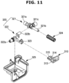
- FIG. 11 is an exploded view illustrating the structure of the locking unit in the refrigerator shown in the FIG. 10 .
- the refrigerator 1 may include the locking unit 300 provided to couple or detach the inner door 41 and the outer door 42.
- the locking unit 300 may include an upper locking unit disposed at the upper portion of the first door 40 to couple or detach the inner door 41 and the first outer door 43 , and a lower locking unit disposed at the lower portion of the first door 40 to couple or detach the inner door 41 and the second outer door 44 and.
- the locking unit 300 provided at the upper portion of the first door 40 is mainly described.
- the inner door frame 69a may include a latch hole 66 through which the locking unit 300 passes.
- the inner door handle 111 may include a first striker hole 311 through which the locking unit 300 passes.
- the latch cover 330 to cover the latch hole 66 may include a second striker hole 312 through which the locking unit 300 penetrating the latch hole 66 passes and a cover cap 331 to cover the second striker hole 312 and the first striker hole 311.
- the cover cap 331 may prevent the beauty from being hindered by the first striker hole 311 and the second striker hole 312 when the outer door 42 is opened only, and at the same time, the cover cap 331 may include a substantially cross-shaped insertion hole so that a striker 310 provided at the outer door 42 is inserted. However, it is not limited thereto.
- the cover cap 331 may include a rubber material.
- the latch cover 330 to cover the latch hole 66 may not be exposed to the outside when viewed from the front.
- the locking unit 300 may prevent the outer door 42 from being opened unintentionally due to inertia when the inner door 41 is opened.
- the locking unit 300 may allow the outer door 42 to be opened although the inner door 41 is closed and prevent the outer door 42 from being opened when the inner door 42 is opened.
- the locking unit 300 may include the striker 310 coupled to the upper portion of the outer door 42, and a latch 320 coupled to the upper portion of the inner door 41 and engaged with or disengaged from the striker 310 in accordance with opening or closing of the inner door 41.
- the latch 320 may include an actuating bar 321 to be pressed by the main body 10 such that the actuating bar 321 is rectilinearly movable, and a rotating bar 322 to perform rotation in accordance with rectilinear movement of the actuating bar 321.
- the rotating bar 322 is provided with an engaging hook 323 formed at one end thereof.
- the latch 320 may include a returning spring 324 to return the actuating bar 321 to an original position thereof when a pressing force from the main body 10 to the actuating bar 321 is released.
- the actuating bar 321 may include a head portion 321a to which the pressing force from the main body 10 is directly applied, and a body portion 321b connected to the head portion 321a.
- the rotating bar 322 may include a rotating shaft 322a as a rotation center, and a connecting shaft 322b connected to the actuating bar 321 to receive drive force from the actuating bar 321.
- the connecting shaft 322b may be arranged to be eccentric from the rotating shaft 322a.
- a connecting hole 321c may be formed at the actuating bar 321 and, as such, the connecting shaft 322b of the rotating bar 322 may be rotatably inserted into the connecting hole 321c.
- the locking unit 300 may include a housing 325 to receive the actuating bar 321, rotating bar 322, and the returning spring 324.
- the housing 325 may be coupled to the upper portion of the inner door 41.
- the striker 310 may include a coupling plate 313 to be coupled to the upper portion of the outer door 42, and an arm bar 315 formed with a coupling hole 314 into which the engaging hook 323 of the latch 320 may be inserted.
- the coupling plate 313 may be coupled to the upper portion of the first outer door 43 by a fastening member (not shown).
- the striker 310 may be formed to have an integrated structure, using stainless steel.
- FIG. 12 is a view illustrating an operation of the locking unit when the inner door and the outer door are opened together in the refrigerator according to an embodiment of the present disclosure.
- FIG. 13 is a view illustrating the operation of the locking unit when only the outer door is opened in the refrigerator according to an embodiment of the present disclosure.
- the actuating bar 321 may be moved in the direction toward the main body 10 by the returning spring 324 to restore the actuating bar 321 to its original position because the pressure applied to the head portion 321a by the main body 10 disappears.
- the engaging hook 323 may be engaged with the engaging groove 314 as the rotating bar 322 is rotated upward in conjunction with the movement of the actuating bar 321.
- the outer door 42 and the inner door 41 may be opened together as the rotating bar 322 and the striker 310 are coupled because the engaging hook 323 is engaged with the engaging groove 314.
- the actuating bar 321 may maintain the position shifted away from the main body 10 because the pressure of the head 321a by the main body 10 is continuously maintained.
- the engaging hook 323 may be released from the engaging groove 314 because the rotating bar 322 may be maintained in a state of being rotated downward by the maintenance position of the actuating bar 321.
- the rotating bar 322 and the striker 310 may be released since the engaging hook 323 is released from the engaging groove 314.
- the outer door 42 may be opened regardless of the inner door 41.
- FIG. 14 is a view illustrating a filling inlet and a rib of an insulating partition wall in the refrigerator according to an embodiment of the present disclosure.
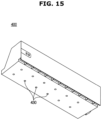
- FIG. 15 is a view illustrating an outlet of the insulating partition wall in the refrigerator shown in the FIG. 14 .
- the refrigerator 1 may include the insulating partition wall 400 positioned between the upper door 51 and the lower door 52 to insulate the inside and the outside of the freezing compartment 20b.
- FIGS. 14 and 15 are an exploded view illustrating the structure of the insulating partition 400 disposed between the upper door 51 and the lower door 52.
- the insulating partition wall 400 may be coupled to the inner case 12 to be filled together with the insulating material (not shown) filled between the inner case 12 and the outer case 11.
- the temperature difference between the inside and the outside of the freezing chamber 20b may be large since the temperature of the freezing chamber 20b is relatively lower than the temperature of the refrigerating chamber 20a. That is, the seal of the insulating partition wall 400 may be required to be larger than that of the refrigerating chamber 20a.
- the insulating partition wall 400 may provide a surface to which the gasket 63 may be adhered by being disposed between the upper door 51 and the lower door 52 like a normal middle partition wall, and furthermore, the insulating partition wall 400 may have better the seal and the insulating property than a normal middle partition wall.
- the insulating partition wall 400 may include a filling inlet 410 connected to the inner case 12 so that the insulating partition wall 400 is filled with the insulating material (not shown) from the inner case 12, and a rib 420 provided adjacent to the filling inlet 410 to prevent leakage of the insulating material (not shown) filled in the insulating partition wall 400 through the filling inlet 410,.
- the filling inlet 410 shown in FIG. 14 is illustrated as being substantially circular, the present disclosure is not limited thereto, and the filling inlet 410 may have various shapes.
- the rib 420 may be configured in a substantially circular shape to correspond to the shape of the filling inlet 410 and provided to be adjacent to the filling inlet 410.
- the ribs 420 may be provided of two ribs corresponding to a single inner rib and a single outer rib.
- the number and position of the ribs 420 are not limited to the above, and may be variously arranged to prevent the leakage of the insulating material (not shown) filled from the inner case 12 into the filling inlet 410.
- the insulating partition wall 400 may include an outlet 430 provided to discharge the gas of the insulating material (not shown) filled into the insulating partition wall 400 to the outside of the insulating partition wall 400.
- a plurality of outlets 430 may be provided at the lower portion of the insulating partition wall 400.
- the present disclosure is not limited thereto, and the outlet 430 may be variously arranged to discharge the gas, which is generated when the insulating material (not shown) is charged from the inner case 12 to the insulating partition wall 400, to the outside of the insulating partition wall 400.
- the insulating partition wall 400 may be sealed to prevent the leakage of the insulating material (not shown).
- the insulating partition wall 400 may be formed separately from the inner case 12 and the outer case 11 and then coupled to the inner case 12 so as to insulate the freezing compartment 20b from the outside..
- a filling connecting hole (not shown) is provided in the inner case 12 so that the insulating material (not shown) is filled into the insulating partition wall 400 through the filling hole 410 provided at one side of the insulating partition wall 400.
- the insulating material (not shown) filled inside the insulating partition wall 400 through a filling connecting hole (not shown) may be the same as the insulating material (not shown) filled between the inner case 12 and the outer case 11.
Landscapes
- Engineering & Computer Science (AREA)
- Mechanical Engineering (AREA)
- Chemical & Material Sciences (AREA)
- Combustion & Propulsion (AREA)
- Physics & Mathematics (AREA)
- Thermal Sciences (AREA)
- General Engineering & Computer Science (AREA)
- Refrigerator Housings (AREA)
Claims (12)
- Kühlschrank (1), umfassend:einen Hauptkörper (10), der ein Aufbewahrungsfach (20) aufweist;eine innere Tür (41), die drehbar mit dem Hauptkörper (10) gekoppelt ist, um das Aufbewahrungsfach (20) zu öffnen und zu schließen, und die einen inneren Türrahmen (69a) aufweist;eine äußere Tür (42), die drehbar mit der inneren Tür (41) gekoppelt ist,einen inneren Türgriff (111), der mit dem inneren Türrahmen (69a) gekoppelt ist, um die innere Tür (41) zusammen mit der äußeren Tür (42) zu öffnen,einen äußeren Türgriff (112), der an der äußeren Tür (42) bereitgestellt ist, um die äußere Tür (42) zu öffnen, unddazu konfiguriert ist, den inneren Türgriff (111) abzudecken;ein Kopplungselement (200), mit dem der innere Türgriff (111) gleitend gekoppelt ist,wobei der innere Türrahmen (69a) ein erstes Kopplungsloch (71), das an einer vorderen Oberfläche des inneren Türrahmens (69a) bereitgestellt ist, und ein zweites Kopplungsloch (72) umfasst, das sich von dem ersten Kopplungsloch (71) erstreckt und größer als das erste Kopplungsloch (71) ist,wobei das Kopplungselement (200) einen ersten Kopplungsabschnitt (210) und einen zweiten Kopplungsabschnitt (220) umfasst, der an der Oberseite des ersten Kopplungsabschnitts (210) bereitgestellt ist,wobei das Kopplungselement (200) gleitend mit dem inneren Türrahmen (69a) gekoppelt ist, sodass der erste Kopplungsabschnitt (210) mit dem ersten Kopplungsloch (71) gekoppelt ist und der zweite Kopplungsabschnitt (220) mit dem zweiten Kopplungsloch (72) gekoppelt ist,wobei der innere Türgriff (111) einen ersten Griffabschnitt (141) beinhaltet, der sich in einer Richtung zum Äußeren der inneren Tür (41) erstreckt, wenn die innere Tür (41) geschlossen ist, wobei der erste Griffabschnitt (141) eine erste Aufnahmenut (115) in dem inneren Türgriff (111) definiert, um die Hand eines Benutzers aufzunehmen,wobei der äußere Türgriff (112) einen zweiten Griffabschnitt (142) beinhaltet, der sich weiter als der erste Griffabschnitt (141) in die eine Richtung zum Äußeren der äußeren Tür (42) hin erstreckt, wenn die äußere Tür (42) geschlossen ist, wobei der zweite Griffabschnitt (142) eine zweite Aufnahmenut (116) in dem äußeren Türgriff (112) definiert, um die Hand eines Benutzers aufzunehmen, um die äußere Tür, die innere Tür ausgenommen, zu öffnen.
- Kühlschrank nach Anspruch 1, wobei das Kopplungselement (200) ferner einen Stützabschnitt (201), der mit einer hinteren Oberfläche des inneren Türrahmens (69a) gekoppelt ist, und einen Rahmeneingriffsabschnitt (202) umfasst, der sich von dem Stützabschnitt (201) nach vorne erstreckt und an der vorderen Oberfläche des inneren Türrahmens (69a) angeordnet ist, sodass das Kopplungselement (200) mit dem inneren Türrahmen (69a) gekoppelt ist.
- Kühlschrank nach Anspruch 2, wobei der Stützabschnitt (201) bereitgestellt ist, um zu verhindern, dass das Kopplungselement (200) von dem ersten Kopplungsloch (71) und dem zweiten Kopplungsloch (72) getrennt wird, und der Rahmeneingriffsabschnitt (202) bereitgestellt ist, um zu verhindern, dass der erste Kopplungsabschnitt (210) von dem ersten Kopplungsloch (71) getrennt wird.
- Kühlschrank nach Anspruch 3, wobei eine Breite des Rahmeneingriffsabschnitts (202) größer als eine Breite des ersten Kopplungslochs (71) und kleiner als eine Breite des zweiten Kopplungslochs (72) ist.
- Kühlschrank nach Anspruch 2, wobei der erste Kopplungsabschnitt (210) einen Griffeingriffsabschnitt (212) umfasst, der sich von dem Rahmeneingriffsabschnitt (202) nach vorne erstreckt, sodass der innere Türgriff (111) mit dem Kopplungselement (200) gekoppelt ist.
- Kühlschrank nach Anspruch 5, wobei der innere Türgriff (111) einen Aufnahmeabschnitt (130) umfasst, der mit dem Kopplungselement (200) gekoppelt ist.
- Kühlschrank nach Anspruch 6, wobei der Aufnahmeabschnitt (130) einen ersten Aufnahmeabschnitt (131), in dem der Rahmeneingriffsabschnitt (202) aufgenommen ist, und einen zweiten Aufnahmeabschnitt (132), in dem der Griffeingriffsabschnitt (212) aufgenommen ist, umfasst.
- Kühlschrank nach Anspruch 7, wobei der Aufnahmeabschnitt (130) ferner einen hervorstehenden Abschnitt (133) umfasst, der nach innen von dem Aufnahmeabschnitt (130) zwischen dem ersten Aufnahmeabschnitt (131) und dem zweiten Aufnahmeabschnitt (132) hervorsteht, um zu verhindern, dass der innere Türgriff (111) von dem Kopplungselement (200) getrennt wird.
- Kühlschrank nach Anspruch 1, wobei der innere Türgriff (111) ein Befestigungselement (160), das bereitgestellt ist, um zu verhindern, dass der innere Türgriff (111) von dem Kopplungselement (200) getrennt wird, und ein Befestigungsloch (170) umfasst, das mit dem Befestigungselement (160) gekoppelt ist.
- Kühlschrank nach Anspruch 9, wobei das Befestigungselement (160) an dem ersten Kopplungsabschnitt (210) und vor dem zweiten Kopplungsabschnitt (220) angeordnet ist, wenn der innere Türgriff (111) mit dem Kopplungselement (200) gekoppelt ist.
- Kühlschrank nach Anspruch 1, wobei die äußere Tür (42) einen Schließbügel (310) umfasst, der an einem oberen Abschnitt der äußeren Tür (42) angeordnet ist, um die äußere Tür (42) mit der inneren Tür (41) zu koppeln oder die äußere Tür (42) von der Inneren (41) zu trennen, und die innere Tür (41) einen Riegel (320), der an dem oberen Abschnitt der inneren Tür (41) bereitgestellt ist und dem Schließbügel (310) entspricht, und eine Riegelabdeckung (330) umfasst, die an einer vorderen Oberfläche des inneren Türrahmens (69a) angeordnet ist, um den Riegel (320) und den Schließbügel (310) aufzunehmen.
- Kühlschrank nach Anspruch 11, wobei der innere Türgriff (111) ein erstes Schließbügelloch (311) umfasst, das an einem oberen Abschnitt des inneren Türgriffs (111) angeordnet ist, sodass der Schließbügel (310) durch das erste Schließbügelloch (311) verläuft, und die Riegelabdeckung (330) ein zweites Schließbügelloch (312), das so bereitgestellt ist, dass es dem ersten Schließbügelloch (311) entspricht, und eine Abdeckkappe (331) umfasst, die so bereitgestellt ist, dass sie das erste Schließbügelloch (311) und das zweite Schließbügelloch (312) abdeckt.
Applications Claiming Priority (2)
| Application Number | Priority Date | Filing Date | Title |
|---|---|---|---|
| KR1020170109599A KR102470041B1 (ko) | 2017-08-29 | 2017-08-29 | 냉장고 |
| PCT/KR2018/009346 WO2019045328A1 (ko) | 2017-08-29 | 2018-08-14 | 냉장고 |
Publications (3)
| Publication Number | Publication Date |
|---|---|
| EP3653977A1 EP3653977A1 (de) | 2020-05-20 |
| EP3653977A4 EP3653977A4 (de) | 2020-08-12 |
| EP3653977B1 true EP3653977B1 (de) | 2024-10-02 |
Family
ID=65525735
Family Applications (1)
| Application Number | Title | Priority Date | Filing Date |
|---|---|---|---|
| EP18849569.1A Active EP3653977B1 (de) | 2017-08-29 | 2018-08-14 | Kühlschrank |
Country Status (5)
| Country | Link |
|---|---|
| US (1) | US11635247B2 (de) |
| EP (1) | EP3653977B1 (de) |
| KR (1) | KR102470041B1 (de) |
| CN (1) | CN111051800B (de) |
| WO (1) | WO2019045328A1 (de) |
Cited By (1)
| Publication number | Priority date | Publication date | Assignee | Title |
|---|---|---|---|---|
| RU2857108C2 (ru) * | 2024-04-01 | 2026-02-25 | Общество с ограниченной ответственностью "Системы и приборы автоматики" (ООО "СПА") | Электромеханический замок для сдвижных дверей |
Families Citing this family (2)
| Publication number | Priority date | Publication date | Assignee | Title |
|---|---|---|---|---|
| DK180889B1 (en) * | 2020-02-14 | 2022-06-14 | Rehau Behr As | Glass door with a handle device |
| KR20210106270A (ko) * | 2020-02-20 | 2021-08-30 | 삼성전자주식회사 | 냉장고 |
Citations (3)
| Publication number | Priority date | Publication date | Assignee | Title |
|---|---|---|---|---|
| US20050161461A1 (en) * | 2004-01-28 | 2005-07-28 | Samsung Electronics Co., Ltd. | Refrigerator |
| US8732910B1 (en) * | 2013-02-28 | 2014-05-27 | General Electric Companmy | Appliance handle assembly |
| KR20160023741A (ko) * | 2016-02-11 | 2016-03-03 | 삼성전자주식회사 | 이중 도어를 갖는 냉장고 |
Family Cites Families (28)
| Publication number | Priority date | Publication date | Assignee | Title |
|---|---|---|---|---|
| US2459658A (en) * | 1947-11-13 | 1949-01-18 | Calorie Stove Corp | Detachable handle |
| US3648411A (en) * | 1970-11-13 | 1972-03-14 | Gen Motors Corp | Refrigerator door trim handles and mounting strip |
| JPS5918277A (ja) | 1982-07-23 | 1984-01-30 | Toyota Motor Corp | デイ−ゼルエンジンのグロ−制御方法および装置 |
| JPS5918277U (ja) * | 1982-07-28 | 1984-02-03 | 日本電気ホームエレクトロニクス株式会社 | 冷蔵庫 |
| JPS6189790A (ja) | 1984-10-08 | 1986-05-07 | Sony Corp | 固体カラ−撮像装置 |
| JPH024392Y2 (de) * | 1984-11-15 | 1990-02-01 | ||
| JPS61153895A (ja) | 1984-12-27 | 1986-07-12 | Toshiba Corp | 半導体記憶装置 |
| JPS61153895U (de) * | 1985-03-14 | 1986-09-24 | ||
| JPS6242661A (ja) | 1985-08-20 | 1987-02-24 | Fujitsu Ltd | 給電電流制限回路 |
| JPS6242661U (de) * | 1985-09-03 | 1987-03-14 | ||
| JPS62152183A (ja) | 1985-12-25 | 1987-07-07 | Kyocera Corp | 太陽電池モジユ−ル |
| JPS62152183U (de) * | 1986-03-19 | 1987-09-26 | ||
| IT218368Z2 (it) | 1989-02-03 | 1992-05-05 | Zanussi A Spa Industrie | Maniglia per porte di apparecchiature refrigeranti. |
| JPH109757A (ja) * | 1996-06-26 | 1998-01-16 | Matsushita Refrig Co Ltd | 冷蔵庫 |
| US6053544A (en) | 1998-05-11 | 2000-04-25 | White Consoldiated Industries, Inc. | Locking handle for refrigerators |
| US6871385B2 (en) * | 2002-07-16 | 2005-03-29 | Maytag Corporation | Refrigerator handle mounting arrangement |
| DE10308629A1 (de) * | 2003-02-27 | 2004-09-09 | BSH Bosch und Siemens Hausgeräte GmbH | Türgriff |
| US7870647B2 (en) * | 2005-03-11 | 2011-01-18 | General Electric Company | Methods and apparatus for assembling a door handle assembly |
| KR20070065743A (ko) * | 2005-12-20 | 2007-06-25 | 주식회사 대우일렉트로닉스 | 냉장고의 도어핸들 고정구조 |
| KR20080100622A (ko) * | 2007-05-14 | 2008-11-19 | 엘지전자 주식회사 | 냉장고의 도어핸들 장착구조 |
| KR102043745B1 (ko) * | 2012-10-26 | 2019-11-12 | 주식회사 위니아딤채 | 냉장고 |
| KR101860718B1 (ko) * | 2013-02-21 | 2018-05-24 | 삼성전자주식회사 | 이중 도어를 갖는 냉장고 |
| KR20140104640A (ko) | 2013-02-21 | 2014-08-29 | 삼성전자주식회사 | 이중 도어를 갖는 냉장고 |
| KR101622228B1 (ko) | 2014-02-21 | 2016-05-18 | 엘지전자 주식회사 | 냉장고 |
| KR102206179B1 (ko) * | 2014-03-11 | 2021-01-22 | 삼성전자주식회사 | 냉장고 |
| KR102098689B1 (ko) * | 2015-07-08 | 2020-04-08 | 삼성전자주식회사 | 냉장고 |
| KR102499268B1 (ko) | 2015-12-02 | 2023-02-13 | 삼성전자주식회사 | 냉장고 |
| CN105546912A (zh) * | 2015-12-21 | 2016-05-04 | 青岛海尔股份有限公司 | 冰箱 |
-
2017
- 2017-08-29 KR KR1020170109599A patent/KR102470041B1/ko active Active
-
2018
- 2018-08-14 EP EP18849569.1A patent/EP3653977B1/de active Active
- 2018-08-14 WO PCT/KR2018/009346 patent/WO2019045328A1/ko not_active Ceased
- 2018-08-14 CN CN201880056262.6A patent/CN111051800B/zh active Active
- 2018-08-14 US US16/643,691 patent/US11635247B2/en active Active
Patent Citations (3)
| Publication number | Priority date | Publication date | Assignee | Title |
|---|---|---|---|---|
| US20050161461A1 (en) * | 2004-01-28 | 2005-07-28 | Samsung Electronics Co., Ltd. | Refrigerator |
| US8732910B1 (en) * | 2013-02-28 | 2014-05-27 | General Electric Companmy | Appliance handle assembly |
| KR20160023741A (ko) * | 2016-02-11 | 2016-03-03 | 삼성전자주식회사 | 이중 도어를 갖는 냉장고 |
Cited By (1)
| Publication number | Priority date | Publication date | Assignee | Title |
|---|---|---|---|---|
| RU2857108C2 (ru) * | 2024-04-01 | 2026-02-25 | Общество с ограниченной ответственностью "Системы и приборы автоматики" (ООО "СПА") | Электромеханический замок для сдвижных дверей |
Also Published As
| Publication number | Publication date |
|---|---|
| US11635247B2 (en) | 2023-04-25 |
| KR102470041B1 (ko) | 2022-11-23 |
| WO2019045328A1 (ko) | 2019-03-07 |
| EP3653977A4 (de) | 2020-08-12 |
| CN111051800B (zh) | 2022-04-12 |
| CN111051800A (zh) | 2020-04-21 |
| US20210156606A1 (en) | 2021-05-27 |
| KR20190023605A (ko) | 2019-03-08 |
| EP3653977A1 (de) | 2020-05-20 |
Similar Documents
| Publication | Publication Date | Title |
|---|---|---|
| EP2431688B1 (de) | Kühlvorrichtung | |
| EP3851777B1 (de) | Kühlschrank | |
| KR101203424B1 (ko) | 냉장고 | |
| EP3008268B1 (de) | Fixiervorrichtung | |
| EP2520885B1 (de) | Kühlschrank | |
| KR20210125379A (ko) | 냉장고 | |
| EP3792573B1 (de) | Kühlschrank | |
| KR20080100553A (ko) | 냉장고의 도어개방구조 | |
| KR20150082065A (ko) | 냉장고 | |
| CN102087068A (zh) | 具有门打开装置的冰箱 | |
| KR20220068124A (ko) | 냉장고 | |
| EP3653977B1 (de) | Kühlschrank | |
| KR20180065633A (ko) | 냉장고 | |
| EP3008409B1 (de) | Kühlschrank | |
| KR101367034B1 (ko) | 트림킷 구조의 냉장고 아웃도어 | |
| KR100839899B1 (ko) | 냉장고용 손잡이 | |
| US11988437B2 (en) | Refrigerator | |
| US12460856B2 (en) | Refrigerator | |
| KR20070012870A (ko) | 냉장고 | |
| KR20250032816A (ko) | 냉장고 | |
| KR200232338Y1 (ko) | 냉장고의열쇠장치 | |
| KR20090105253A (ko) | 냉장고 | |
| KR20150073788A (ko) | 냉장고 |
Legal Events
| Date | Code | Title | Description |
|---|---|---|---|
| STAA | Information on the status of an ep patent application or granted ep patent |
Free format text: STATUS: THE INTERNATIONAL PUBLICATION HAS BEEN MADE |
|
| PUAI | Public reference made under article 153(3) epc to a published international application that has entered the european phase |
Free format text: ORIGINAL CODE: 0009012 |
|
| STAA | Information on the status of an ep patent application or granted ep patent |
Free format text: STATUS: REQUEST FOR EXAMINATION WAS MADE |
|
| 17P | Request for examination filed |
Effective date: 20200214 |
|
| AK | Designated contracting states |
Kind code of ref document: A1 Designated state(s): AL AT BE BG CH CY CZ DE DK EE ES FI FR GB GR HR HU IE IS IT LI LT LU LV MC MK MT NL NO PL PT RO RS SE SI SK SM TR |
|
| AX | Request for extension of the european patent |
Extension state: BA ME |
|
| A4 | Supplementary search report drawn up and despatched |
Effective date: 20200715 |
|
| RIC1 | Information provided on ipc code assigned before grant |
Ipc: E05C 7/02 20060101ALI20200709BHEP Ipc: E05B 1/00 20060101ALI20200709BHEP Ipc: F25D 23/02 20060101AFI20200709BHEP |
|
| DAV | Request for validation of the european patent (deleted) | ||
| DAX | Request for extension of the european patent (deleted) | ||
| STAA | Information on the status of an ep patent application or granted ep patent |
Free format text: STATUS: EXAMINATION IS IN PROGRESS |
|
| 17Q | First examination report despatched |
Effective date: 20220826 |
|
| GRAP | Despatch of communication of intention to grant a patent |
Free format text: ORIGINAL CODE: EPIDOSNIGR1 |
|
| STAA | Information on the status of an ep patent application or granted ep patent |
Free format text: STATUS: GRANT OF PATENT IS INTENDED |
|
| GRAS | Grant fee paid |
Free format text: ORIGINAL CODE: EPIDOSNIGR3 |
|
| INTG | Intention to grant announced |
Effective date: 20240712 |
|
| GRAA | (expected) grant |
Free format text: ORIGINAL CODE: 0009210 |
|
| STAA | Information on the status of an ep patent application or granted ep patent |
Free format text: STATUS: THE PATENT HAS BEEN GRANTED |
|
| AK | Designated contracting states |
Kind code of ref document: B1 Designated state(s): AL AT BE BG CH CY CZ DE DK EE ES FI FR GB GR HR HU IE IS IT LI LT LU LV MC MK MT NL NO PL PT RO RS SE SI SK SM TR |
|
| REG | Reference to a national code |
Ref country code: GB Ref legal event code: FG4D |
|
| REG | Reference to a national code |
Ref country code: CH Ref legal event code: EP |
|
| REG | Reference to a national code |
Ref country code: DE Ref legal event code: R096 Ref document number: 602018075036 Country of ref document: DE |
|
| REG | Reference to a national code |
Ref country code: IE Ref legal event code: FG4D |
|
| REG | Reference to a national code |
Ref country code: LT Ref legal event code: MG9D |
|
| REG | Reference to a national code |
Ref country code: NL Ref legal event code: MP Effective date: 20241002 |
|
| REG | Reference to a national code |
Ref country code: AT Ref legal event code: MK05 Ref document number: 1728773 Country of ref document: AT Kind code of ref document: T Effective date: 20241002 |
|
| PG25 | Lapsed in a contracting state [announced via postgrant information from national office to epo] |
Ref country code: NL Free format text: LAPSE BECAUSE OF FAILURE TO SUBMIT A TRANSLATION OF THE DESCRIPTION OR TO PAY THE FEE WITHIN THE PRESCRIBED TIME-LIMIT Effective date: 20241002 |
|
| PG25 | Lapsed in a contracting state [announced via postgrant information from national office to epo] |
Ref country code: NL Free format text: LAPSE BECAUSE OF FAILURE TO SUBMIT A TRANSLATION OF THE DESCRIPTION OR TO PAY THE FEE WITHIN THE PRESCRIBED TIME-LIMIT Effective date: 20241002 |
|
| PG25 | Lapsed in a contracting state [announced via postgrant information from national office to epo] |
Ref country code: HR Free format text: LAPSE BECAUSE OF FAILURE TO SUBMIT A TRANSLATION OF THE DESCRIPTION OR TO PAY THE FEE WITHIN THE PRESCRIBED TIME-LIMIT Effective date: 20241002 Ref country code: PT Free format text: LAPSE BECAUSE OF FAILURE TO SUBMIT A TRANSLATION OF THE DESCRIPTION OR TO PAY THE FEE WITHIN THE PRESCRIBED TIME-LIMIT Effective date: 20250203 Ref country code: IS Free format text: LAPSE BECAUSE OF FAILURE TO SUBMIT A TRANSLATION OF THE DESCRIPTION OR TO PAY THE FEE WITHIN THE PRESCRIBED TIME-LIMIT Effective date: 20250202 |
|
| PG25 | Lapsed in a contracting state [announced via postgrant information from national office to epo] |
Ref country code: FI Free format text: LAPSE BECAUSE OF FAILURE TO SUBMIT A TRANSLATION OF THE DESCRIPTION OR TO PAY THE FEE WITHIN THE PRESCRIBED TIME-LIMIT Effective date: 20241002 |
|
| PG25 | Lapsed in a contracting state [announced via postgrant information from national office to epo] |
Ref country code: BG Free format text: LAPSE BECAUSE OF FAILURE TO SUBMIT A TRANSLATION OF THE DESCRIPTION OR TO PAY THE FEE WITHIN THE PRESCRIBED TIME-LIMIT Effective date: 20241002 |
|
| PG25 | Lapsed in a contracting state [announced via postgrant information from national office to epo] |
Ref country code: ES Free format text: LAPSE BECAUSE OF FAILURE TO SUBMIT A TRANSLATION OF THE DESCRIPTION OR TO PAY THE FEE WITHIN THE PRESCRIBED TIME-LIMIT Effective date: 20241002 |
|
| PG25 | Lapsed in a contracting state [announced via postgrant information from national office to epo] |
Ref country code: NO Free format text: LAPSE BECAUSE OF FAILURE TO SUBMIT A TRANSLATION OF THE DESCRIPTION OR TO PAY THE FEE WITHIN THE PRESCRIBED TIME-LIMIT Effective date: 20250102 |
|
| PG25 | Lapsed in a contracting state [announced via postgrant information from national office to epo] |
Ref country code: AT Free format text: LAPSE BECAUSE OF FAILURE TO SUBMIT A TRANSLATION OF THE DESCRIPTION OR TO PAY THE FEE WITHIN THE PRESCRIBED TIME-LIMIT Effective date: 20241002 Ref country code: LV Free format text: LAPSE BECAUSE OF FAILURE TO SUBMIT A TRANSLATION OF THE DESCRIPTION OR TO PAY THE FEE WITHIN THE PRESCRIBED TIME-LIMIT Effective date: 20241002 Ref country code: GR Free format text: LAPSE BECAUSE OF FAILURE TO SUBMIT A TRANSLATION OF THE DESCRIPTION OR TO PAY THE FEE WITHIN THE PRESCRIBED TIME-LIMIT Effective date: 20250103 |
|
| PG25 | Lapsed in a contracting state [announced via postgrant information from national office to epo] |
Ref country code: CZ Free format text: LAPSE BECAUSE OF FAILURE TO SUBMIT A TRANSLATION OF THE DESCRIPTION OR TO PAY THE FEE WITHIN THE PRESCRIBED TIME-LIMIT Effective date: 20241002 Ref country code: PL Free format text: LAPSE BECAUSE OF FAILURE TO SUBMIT A TRANSLATION OF THE DESCRIPTION OR TO PAY THE FEE WITHIN THE PRESCRIBED TIME-LIMIT Effective date: 20241002 |
|
| PG25 | Lapsed in a contracting state [announced via postgrant information from national office to epo] |
Ref country code: RS Free format text: LAPSE BECAUSE OF FAILURE TO SUBMIT A TRANSLATION OF THE DESCRIPTION OR TO PAY THE FEE WITHIN THE PRESCRIBED TIME-LIMIT Effective date: 20250102 |
|
| PG25 | Lapsed in a contracting state [announced via postgrant information from national office to epo] |
Ref country code: SM Free format text: LAPSE BECAUSE OF FAILURE TO SUBMIT A TRANSLATION OF THE DESCRIPTION OR TO PAY THE FEE WITHIN THE PRESCRIBED TIME-LIMIT Effective date: 20241002 |
|
| REG | Reference to a national code |
Ref country code: DE Ref legal event code: R097 Ref document number: 602018075036 Country of ref document: DE |
|
| PG25 | Lapsed in a contracting state [announced via postgrant information from national office to epo] |
Ref country code: DK Free format text: LAPSE BECAUSE OF FAILURE TO SUBMIT A TRANSLATION OF THE DESCRIPTION OR TO PAY THE FEE WITHIN THE PRESCRIBED TIME-LIMIT Effective date: 20241002 |
|
| PG25 | Lapsed in a contracting state [announced via postgrant information from national office to epo] |
Ref country code: EE Free format text: LAPSE BECAUSE OF FAILURE TO SUBMIT A TRANSLATION OF THE DESCRIPTION OR TO PAY THE FEE WITHIN THE PRESCRIBED TIME-LIMIT Effective date: 20241002 |
|
| PG25 | Lapsed in a contracting state [announced via postgrant information from national office to epo] |
Ref country code: RO Free format text: LAPSE BECAUSE OF FAILURE TO SUBMIT A TRANSLATION OF THE DESCRIPTION OR TO PAY THE FEE WITHIN THE PRESCRIBED TIME-LIMIT Effective date: 20241002 |
|
| PG25 | Lapsed in a contracting state [announced via postgrant information from national office to epo] |
Ref country code: SK Free format text: LAPSE BECAUSE OF FAILURE TO SUBMIT A TRANSLATION OF THE DESCRIPTION OR TO PAY THE FEE WITHIN THE PRESCRIBED TIME-LIMIT Effective date: 20241002 |
|
| PG25 | Lapsed in a contracting state [announced via postgrant information from national office to epo] |
Ref country code: IT Free format text: LAPSE BECAUSE OF FAILURE TO SUBMIT A TRANSLATION OF THE DESCRIPTION OR TO PAY THE FEE WITHIN THE PRESCRIBED TIME-LIMIT Effective date: 20241002 |
|
| PLBE | No opposition filed within time limit |
Free format text: ORIGINAL CODE: 0009261 |
|
| STAA | Information on the status of an ep patent application or granted ep patent |
Free format text: STATUS: NO OPPOSITION FILED WITHIN TIME LIMIT |
|
| PG25 | Lapsed in a contracting state [announced via postgrant information from national office to epo] |
Ref country code: SE Free format text: LAPSE BECAUSE OF FAILURE TO SUBMIT A TRANSLATION OF THE DESCRIPTION OR TO PAY THE FEE WITHIN THE PRESCRIBED TIME-LIMIT Effective date: 20241002 |
|
| 26N | No opposition filed |
Effective date: 20250703 |
|
| PGFP | Annual fee paid to national office [announced via postgrant information from national office to epo] |
Ref country code: DE Payment date: 20250721 Year of fee payment: 8 |
|
| PGFP | Annual fee paid to national office [announced via postgrant information from national office to epo] |
Ref country code: GB Payment date: 20250722 Year of fee payment: 8 |
|
| REG | Reference to a national code |
Ref country code: CH Ref legal event code: H13 Free format text: ST27 STATUS EVENT CODE: U-0-0-H10-H13 (AS PROVIDED BY THE NATIONAL OFFICE) Effective date: 20260324 |
|
| PG25 | Lapsed in a contracting state [announced via postgrant information from national office to epo] |
Ref country code: MC Free format text: LAPSE BECAUSE OF FAILURE TO SUBMIT A TRANSLATION OF THE DESCRIPTION OR TO PAY THE FEE WITHIN THE PRESCRIBED TIME-LIMIT Effective date: 20241002 |
|
| PG25 | Lapsed in a contracting state [announced via postgrant information from national office to epo] |
Ref country code: LU Free format text: LAPSE BECAUSE OF NON-PAYMENT OF DUE FEES Effective date: 20250814 |
|
| PG25 | Lapsed in a contracting state [announced via postgrant information from national office to epo] |
Ref country code: CH Free format text: LAPSE BECAUSE OF NON-PAYMENT OF DUE FEES Effective date: 20250831 |