EP3655224B1 - Pompe à déplacement positif à membrane rotative - Google Patents
Pompe à déplacement positif à membrane rotative Download PDFInfo
- Publication number
- EP3655224B1 EP3655224B1 EP18745675.1A EP18745675A EP3655224B1 EP 3655224 B1 EP3655224 B1 EP 3655224B1 EP 18745675 A EP18745675 A EP 18745675A EP 3655224 B1 EP3655224 B1 EP 3655224B1
- Authority
- EP
- European Patent Office
- Prior art keywords
- diaphragm
- end cap
- housing
- critical
- plastic
- Prior art date
- Legal status (The legal status is an assumption and is not a legal conclusion. Google has not performed a legal analysis and makes no representation as to the accuracy of the status listed.)
- Active
Links
Images

Classifications
-
- B—PERFORMING OPERATIONS; TRANSPORTING
- B29—WORKING OF PLASTICS; WORKING OF SUBSTANCES IN A PLASTIC STATE IN GENERAL
- B29C—SHAPING OR JOINING OF PLASTICS; SHAPING OF MATERIAL IN A PLASTIC STATE, NOT OTHERWISE PROVIDED FOR; AFTER-TREATMENT OF THE SHAPED PRODUCTS, e.g. REPAIRING
- B29C45/00—Injection moulding, i.e. forcing the required volume of moulding material through a nozzle into a closed mould; Apparatus therefor
- B29C45/0025—Preventing defects on the moulded article, e.g. weld lines, shrinkage marks
-
- B—PERFORMING OPERATIONS; TRANSPORTING
- B29—WORKING OF PLASTICS; WORKING OF SUBSTANCES IN A PLASTIC STATE IN GENERAL
- B29C—SHAPING OR JOINING OF PLASTICS; SHAPING OF MATERIAL IN A PLASTIC STATE, NOT OTHERWISE PROVIDED FOR; AFTER-TREATMENT OF THE SHAPED PRODUCTS, e.g. REPAIRING
- B29C45/00—Injection moulding, i.e. forcing the required volume of moulding material through a nozzle into a closed mould; Apparatus therefor
- B29C45/17—Component parts, details or accessories; Auxiliary operations
- B29C45/26—Moulds
- B29C45/2616—Moulds having annular mould cavities
-
- B—PERFORMING OPERATIONS; TRANSPORTING
- B29—WORKING OF PLASTICS; WORKING OF SUBSTANCES IN A PLASTIC STATE IN GENERAL
- B29C—SHAPING OR JOINING OF PLASTICS; SHAPING OF MATERIAL IN A PLASTIC STATE, NOT OTHERWISE PROVIDED FOR; AFTER-TREATMENT OF THE SHAPED PRODUCTS, e.g. REPAIRING
- B29C45/00—Injection moulding, i.e. forcing the required volume of moulding material through a nozzle into a closed mould; Apparatus therefor
- B29C45/0046—Details relating to the filling pattern or flow paths or flow characteristics of moulding material in the mould cavity
-
- B—PERFORMING OPERATIONS; TRANSPORTING
- B29—WORKING OF PLASTICS; WORKING OF SUBSTANCES IN A PLASTIC STATE IN GENERAL
- B29C—SHAPING OR JOINING OF PLASTICS; SHAPING OF MATERIAL IN A PLASTIC STATE, NOT OTHERWISE PROVIDED FOR; AFTER-TREATMENT OF THE SHAPED PRODUCTS, e.g. REPAIRING
- B29C45/00—Injection moulding, i.e. forcing the required volume of moulding material through a nozzle into a closed mould; Apparatus therefor
- B29C45/17—Component parts, details or accessories; Auxiliary operations
- B29C45/26—Moulds
- B29C45/261—Moulds having tubular mould cavities
-
- B—PERFORMING OPERATIONS; TRANSPORTING
- B29—WORKING OF PLASTICS; WORKING OF SUBSTANCES IN A PLASTIC STATE IN GENERAL
- B29D—PRODUCING PARTICULAR ARTICLES FROM PLASTICS OR FROM SUBSTANCES IN A PLASTIC STATE
- B29D99/00—Subject matter not provided for in other groups of this subclass
- B29D99/0032—Producing rolling bodies, e.g. rollers, wheels, pulleys or pinions
-
- F—MECHANICAL ENGINEERING; LIGHTING; HEATING; WEAPONS; BLASTING
- F04—POSITIVE - DISPLACEMENT MACHINES FOR LIQUIDS; PUMPS FOR LIQUIDS OR ELASTIC FLUIDS
- F04B—POSITIVE-DISPLACEMENT MACHINES FOR LIQUIDS; PUMPS
- F04B43/00—Machines, pumps, or pumping installations having flexible working members
-
- F—MECHANICAL ENGINEERING; LIGHTING; HEATING; WEAPONS; BLASTING
- F04—POSITIVE - DISPLACEMENT MACHINES FOR LIQUIDS; PUMPS FOR LIQUIDS OR ELASTIC FLUIDS
- F04C—ROTARY-PISTON, OR OSCILLATING-PISTON, POSITIVE-DISPLACEMENT MACHINES FOR LIQUIDS; ROTARY-PISTON, OR OSCILLATING-PISTON, POSITIVE-DISPLACEMENT PUMPS
- F04C5/00—Rotary-piston machines or pumps with the working-chamber walls at least partly resiliently deformable
-
- B—PERFORMING OPERATIONS; TRANSPORTING
- B29—WORKING OF PLASTICS; WORKING OF SUBSTANCES IN A PLASTIC STATE IN GENERAL
- B29C—SHAPING OR JOINING OF PLASTICS; SHAPING OF MATERIAL IN A PLASTIC STATE, NOT OTHERWISE PROVIDED FOR; AFTER-TREATMENT OF THE SHAPED PRODUCTS, e.g. REPAIRING
- B29C45/00—Injection moulding, i.e. forcing the required volume of moulding material through a nozzle into a closed mould; Apparatus therefor
- B29C45/0025—Preventing defects on the moulded article, e.g. weld lines, shrinkage marks
- B29C2045/0027—Gate or gate mark locations
-
- B—PERFORMING OPERATIONS; TRANSPORTING
- B29—WORKING OF PLASTICS; WORKING OF SUBSTANCES IN A PLASTIC STATE IN GENERAL
- B29C—SHAPING OR JOINING OF PLASTICS; SHAPING OF MATERIAL IN A PLASTIC STATE, NOT OTHERWISE PROVIDED FOR; AFTER-TREATMENT OF THE SHAPED PRODUCTS, e.g. REPAIRING
- B29C45/00—Injection moulding, i.e. forcing the required volume of moulding material through a nozzle into a closed mould; Apparatus therefor
- B29C45/17—Component parts, details or accessories; Auxiliary operations
- B29C45/26—Moulds
- B29C45/27—Sprue channels ; Runner channels or runner nozzles
- B29C45/2701—Details not specific to hot or cold runner channels
- B29C45/2708—Gates
-
- B—PERFORMING OPERATIONS; TRANSPORTING
- B29—WORKING OF PLASTICS; WORKING OF SUBSTANCES IN A PLASTIC STATE IN GENERAL
- B29K—INDEXING SCHEME ASSOCIATED WITH SUBCLASSES B29B, B29C OR B29D, RELATING TO MOULDING MATERIALS OR TO MATERIALS FOR MOULDS, REINFORCEMENTS, FILLERS OR PREFORMED PARTS, e.g. INSERTS
- B29K2077/00—Use of PA, i.e. polyamides, e.g. polyesteramides or derivatives thereof, as moulding material
-
- B—PERFORMING OPERATIONS; TRANSPORTING
- B29—WORKING OF PLASTICS; WORKING OF SUBSTANCES IN A PLASTIC STATE IN GENERAL
- B29K—INDEXING SCHEME ASSOCIATED WITH SUBCLASSES B29B, B29C OR B29D, RELATING TO MOULDING MATERIALS OR TO MATERIALS FOR MOULDS, REINFORCEMENTS, FILLERS OR PREFORMED PARTS, e.g. INSERTS
- B29K2105/00—Condition, form or state of moulded material or of the material to be shaped
- B29K2105/06—Condition, form or state of moulded material or of the material to be shaped containing reinforcements, fillers or inserts
- B29K2105/12—Condition, form or state of moulded material or of the material to be shaped containing reinforcements, fillers or inserts of short lengths, e.g. chopped filaments, staple fibres or bristles
-
- B—PERFORMING OPERATIONS; TRANSPORTING
- B29—WORKING OF PLASTICS; WORKING OF SUBSTANCES IN A PLASTIC STATE IN GENERAL
- B29L—INDEXING SCHEME ASSOCIATED WITH SUBCLASS B29C, RELATING TO PARTICULAR ARTICLES
- B29L2031/00—Other particular articles
- B29L2031/748—Machines or parts thereof not otherwise provided for
- B29L2031/7496—Pumps
-
- F—MECHANICAL ENGINEERING; LIGHTING; HEATING; WEAPONS; BLASTING
- F04—POSITIVE - DISPLACEMENT MACHINES FOR LIQUIDS; PUMPS FOR LIQUIDS OR ELASTIC FLUIDS
- F04C—ROTARY-PISTON, OR OSCILLATING-PISTON, POSITIVE-DISPLACEMENT MACHINES FOR LIQUIDS; ROTARY-PISTON, OR OSCILLATING-PISTON, POSITIVE-DISPLACEMENT PUMPS
- F04C2230/00—Manufacture
- F04C2230/20—Manufacture essentially without removing material
Definitions
- the present invention relates to a rotary diaphragm positive displacement pump. Such a pump is disclosed in our own earlier EP0819853 .
- Such a rotary pump comprises a housing defining an annular chamber with inlet and outlet ports spaced apart around the chamber, a flexible annular diaphragm forming one side of the chamber spaced opposite an annular wall of the housing, the diaphragm being sealed at its edge to the housing, a partition extending across the chamber from a location between the inlet and outlet ports to the diaphragm; wherein the diaphragm is configured to be pressed progressively against the opposite wall of the housing to force fluid drawn in at the inlet port on one side of the partition around the chamber and to expel it at the outlet port at the other side of the partition.
- a rotary pump will subsequently be described as "of the kind described”.
- JP 2009/243349 , GB2037371 and EP0053868 provide other examples of pumps with end caps.
- US 2013/240528 and EP1457300 disclose gating mechanisms for a mould.
- the rotary pump has a pair of end caps. These have traditionally been machined as the ring is required to have some very tight tolerances. This is particularly so of the radially outer most face which is required to engage with the diaphragm in order to compress the diaphragm against the outer housing and provide the seal between the edge of the diaphragm and the housing.
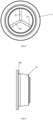
- This method takes the apparently counterintuitive step of forming a cap with a critical radially facing surface which is deliberately not intended to be perfectly circular. Instead, it is deliberately engineered with high points and low points at predetermined locations around the circumference of the critical surface. This is achieved by having a number of substantially equally circumferentially spaced gates around the mould. As these inject simultaneously around the mould, the plastic material will generally travel symmetrically away from each of the gates as it fills the cavity as a result of which low points will be formed at locations which are furthest from the gates while high points will be formed at locations adjacent to the gates.
- the end cap preferably has a wall thickness that is larger at one end than the other.
- the critical radially facing surface with a radius which varies periodically around the circumference provides the benefits mentioned above in relation to the method.
- the radius is at a maximum at at least three portions around a circumference of the critical radially facing surface.
- the radius of the critical radially facing surface should still be controlled to a reasonable extent such that a radius varies by no more than +/- 0.04 mm and preferably +/- 0.03 mm.
- Each end cap is preferably a plastic and is more preferably a hard composite plastic such as glass filled nylon.
- the end cap for the rotary pump according to the second aspect of the present invention is preferably formed according to a method of the first aspect.
- the configuration of the rotary pump is preferably such that the diaphragm does not rotate relative to the housing.
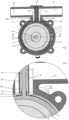
- a tubular part of a rigid housing 1 has an annular groove 2 running around the inner surface, which acts as the pump chamber.
- a flexible diaphragm 3 lies inside the wall of the housing leaving the groove free to contain the pumped fluid.
- a rigid reinforcing ring 4 is moulded into the diaphragm and this ring is at all times in intimate contact with an outer surface of a bearing 5 mounted via an eccentric coupling 6 which extends through and is mounted in the housing in bearings (not shown).
- the shaft 6 is mounted concentrically with the annular groove but eccentrically with regard to the axis 8 of the housing 1 and is powered by a motor (not shown). If the reinforcing ring were not present, the diaphragm would stretch and the performance would be reduced in a similar way to that experienced with peristaltic pumps, when the tubing collapses under vacuum.
- the bearing 5, reinforcing ring 4 and central portion of the diaphragm 3 all orbit together inside the housing.
- the two ends of the diaphragm 3 are clamped to the housing 1 by end caps 9, providing an effective and static seal to atmosphere.
- line contact 10 exists between the diaphragm and the groove providing an abutment which pushes the fluid along towards the outlet port 11 and simultaneously draws fluid in through the inlet port 12.
- the pump thus provides pressure and suction cycles at the output and intake respectively which are symmetrical and which vary sinusoidally. Since the diaphragm does not rotate relative to the housing, there is minimal sliding action between them and therefore almost no wear.
- FIG. 1 it can be seen that another feature of the diaphragm moulding is an elastic partition 13 which prevents communication between the outlet 11 and inlet 12 ports. This is positioned between downwardly depending walls 14, 15 which are part of the housing Since the partition is elastic, it accommodates the reciprocating movement of the diaphragm whilst maintaining a static pressure seal between both ports and atmosphere. In this way, all compliant sealing functions required by the pump are provided by the diaphragm moulding and since none of these are sliding seals, they are not subject to significant wear.
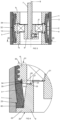
- the end caps 9 are best shown in Fig 4 . These have a first end 20 at the outermost face of the end cap and a second end 21 at the opposite innermost face. At the first end 20 is a radially outwardly extending flange 22 which, clamps the diaphragm 3 to the housing 1 with the cooperation of an annular flange 23 in the housing 1.
- the end cap 9 has a tapered outer face 24 tapering inwardly away from the first end 20. This outer face 24 supports the diaphragm 3 when the diaphragm is in its radially innermost position as shown in the right hand of Fig 3 .
- annular projection 25 At the radially innermost portion of the second end 21 is an annular projection 25.
- the presence of this projection 25 forms a recess 26 which provides a step reduction in the outer diameter of the end cap 9 in the region adjacent to the second end 21.
- the second end 21 is spaced from the bearing 5 by a very small amount creating a first gap 27, in this case less than 0.4 mm and preferably 0.25 mm.
- a second gap 28 is present between the recess 26 and the reinforcing ring 4. Again, this is less than 0.4 mm and preferably 0.25 mm.
- the end cap 9 is located by engagement with the flange 22 against the flexible diaphragm 3.
- the flange 22 cannot over compress the diaphragm 3 otherwise the end cap 9 will be abut against the reinforcing ring 4 and bearing 5. This ensures that the end cap 9 at either end of the assembly can be inserted consistently as both end caps will compress the diaphragm 3 to the same limited amount.
- the small nature of the second gap 28 also ensures that there is only a very small region of the compressible diaphragm 3 which remains unsupported as the diaphragm 3 is pressed against the end cap 9 (as shown in the right hand side of Fig 3 ). In this position, the opposite outer face of the diaphragm is receiving the full pressure within the pump chamber and this would tend it extrude the diaphragm material in any unsupported region on the opposite side.
- the very small nature of this gap 28 significantly limits the potential for extrusion of the diaphragm 3 even when the pressure in the groove 2 is increased.
- the reinforcement ring 4 has a modified shape as best shown in Figs. 3 and 4 .
- This comprises an embedded portion 30 forming the radially outermost portion of ring 4 and a support portion 31 forming the radially inner most portion of the ring 4.
- the embedded portion 30 has a crenulated configuration in this case consisting of four annular ridges which, in cross section, have a curved configuration which is devoid of sharp corners. This is to avoid any stress concentrations in the ring 4. These crenulations are designed to provide a large surface area within a relatively limited axial region.
- the diaphragm 3 is formed as an over mould on the ring 4 and the presence of the crenulations maximises the surface area for bonding between the two.
- the relatively large number of rings 32 combined with their generally curved cross sections effectively spreads the load transmission between the two components thereby avoiding delamination of the two components even under relatively high loads.
- the support portion 31 of the ring 4 extends axially beyond the crenulations 32 forming diaphragm support portions 34. These have a radially outwardly facing surface 35 which directly faces an inner face of the diaphragm 3.
- the diaphragm 3 is not bonded to the face 35. However, in the position in which the diaphragm 3 is furthest from the housing 1, the diaphragm is supported in this region by the face 35.
- This feature provides support for the diaphragm at a time when it is under a relatively high inward pressure from the pressure within the pump chamber. As is with the gap 28 mentioned above, this support prevents extrusion of the diaphragm material in this stressed position.
- the diaphragm 3 is provided with a trough 40 extended axially across a substantial portion of the diaphragm in the vicinity of the outlet.
- a similar trough 41 is provided at the inlet.
- the trough 40 in each case has a first edge 42 adjacent to the partition 13 and a second edge 43 opposite to the first edge.
- the troughs 40, 41 are aligned with a respective outlet duct 44 and inlet duct 45 which lead to the outlet port 11 and from the inlet port 12 respectively.
- troughs 40, 41 In the absence of these troughs 40, 41 when the diaphragm 3 is in the uppermost position, it is possible that while under high pressure, the diaphragm material will extrude into the port to a limited extent thereby causing damage to the diaphragm over time.
- the presence of the troughs 40, 41 reduces or eliminates this effect.
- trough terminates at edge 43 which is adjacent to the edge of duct 44 so that the full thickness of the diaphragm is available immediately downstream of the edge 43. This means that the diaphragm is able to fully engage with the inlet duct 44 as the diaphragm reaches the top of its travel thereby ensuring that the point contact 10 is maintained up until the outlet duct 44 in order to expel the liquid.
- a similar geometry is provided for the inlet duct 45.
- Reinforcing members 50 are best shown in Figs. 2 , 5 and 6 . Although two such reinforcing members 50 are shown in Fig. 6 , only one of these need be present in practice. This would depend upon the direction in which the partition 13 is loaded in use.
- the reinforcing member 50 comprises a frame of material which is harder than the material of the partition and therefore more resistant to deflection under pressure. This is shaped to fit in a shallow recess 51 in the side of the partition. It is preferably a press fit but maybe, more securely attached if the application requires it. As shown best in Figure 6 , the geometry of the reinforcing member 50 is such that it may be considered as a reinforcing plate, whose thickness is much smaller than its length/width.
- the partition 13 deflects to some extent in order to accommodate this orbital movement.
- the pressure of the fluid in the inlet 12 or outlet 11 will also act to deflect the partition. Under higher pressure loads, this can cause the softer material of the diaphragm to contact the walls 14, 15 thereby wearing the diaphragm material, particularly at the bottom edge of the walls 14, 15 which can dig into the diaphragm 3 material.
- the reinforcing member 50 is positioned in the vicinity of the bottom edge of the walls 14, 15 such that any contact will be between two harder surfaces thereby protecting the diaphragm material from wear.
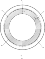
- the end cap 9 has a critical radially facing surface 60.
- This is defined as the critical surface as it is the one which requires the tightest tolerance.
- this surface 60 faces the housing 1 and compresses the diaphragm 3 between the ring 9 and the housing 1.
- this surface is carefully controlled as, if it is not, the primary seal at the edge of the diaphragm will be compromised. Previously, therefore, this component has been machined as this has, to date, been the only way in which we can obtain the necessary tolerance.
- the critical radially facing surface 60 is not perfectly circular, the location of the high points 62 and low points 63 is controlled with a reasonably high degree of precision. This technique of injecting plastic at equal locations in order to form carefully controlled high points and low points has been found to be highly reproducible. In practice the diaphragm 3 is compressed to a slightly greater extent in the vicinity of the high points 62 than it is in the vicinity of the low points 63 but, as these high points and low points can be accurately defined and controlled this is acceptable.
- this represents a moulding technique which has been found to be acceptable for a method of moulding an end cap for a use in a rotary pump.
Landscapes
- Engineering & Computer Science (AREA)
- Mechanical Engineering (AREA)
- Manufacturing & Machinery (AREA)
- General Engineering & Computer Science (AREA)
- Reciprocating Pumps (AREA)
Claims (7)
- Procédé de fabrication d'un capuchon d'extrémité en plastique (9) destiné à être utilisé dans une pompe rotative, dans lequel le capuchon d'extrémité en plastique comprend un axe central et une paroi annulaire définissant une première extrémité, une deuxième extrémité opposée à la première extrémité, et une surface critique orientée radialement (60) s'étendant au moins en partie entre les première et deuxième extrémités,
caractérisé en ce que
le capuchon d'extrémité est formé dans un moule définissant une cavité et comprend au moins trois portes (61) espacées de manière sensiblement égale sur la circonférence, chacune pour injecter du plastique dans la cavité, dans lequel le procédé comprend l'étape consistant à :
injecter simultanément du plastique au niveau des portes (61) pour remplir la cavité de sorte que la surface critique (60) soit formée avec des points hauts (62) et des points bas (63) à des emplacements prédéterminés autour de la circonférence de la surface critique finie. - Procédé de moulage d'un capuchon d'extrémité en plastique selon la revendication 1, dans lequel le capuchon d'extrémité (9) a une épaisseur de paroi qui est plus grande au niveau d'une extrémité qu'au niveau de l'autre et les portes (61) sont positionnées au niveau de l'extrémité du moule correspondant à la plus petite épaisseur de paroi.
- Pompe rotative comprenant :un carter (1) définissant une chambre annulaire (2) avec des orifices d'entrée (12) et de sortie (11) espacés autour de la chambre, un diaphragme annulaire flexible (3) formant un côté de la chambre espacé à l'opposé d'une paroi annulaire du carter et ayant deux extrémités circulaires opposées, le diaphragme étant scellé au niveau de ses bords au carter, une cloison (13) s'étendant à travers la chambre depuis un emplacement entre les orifices d'entrée et de sortie vers le diaphragme ;dans laquelle le diaphragme (3) comprend une surface externe qui s'engage avec la paroi annulaire du carter, et une surface interne opposée à la première surface, dans laquelle la surface externe est configurée pour être pressée progressivement contre la paroi opposée du carter, par un moyen de rotation (7), pour forcer un fluide aspiré au niveau de l'orifice d'entrée d'un côté de la cloison autour de la chambre et pour l'expulser au niveau de l'orifice de sortie de l'autre côté de la cloison ;une bague de renforcement (4) entourant le moyen de rotation et reliée à une région centrale du diaphragme ;une paire de capuchons d'extrémité annulaires (9), un à chaque extrémité du diaphragme, chaque capuchon d'extrémité ayant une première extrémité adjacente à une extrémité respective du diaphragme et une deuxième extrémité opposée à la première extrémité, et une surface critique orientée radialement (60) s'étendant au moins en partie entre les première et deuxième extrémités, la surface critique orientée radialement s'engageant avec la surface interne du diaphragme, caractérisée en ce que la surface critique orientée radialement (60) a un rayon qui varie périodiquement autour de la circonférence ; dans laquelle le rayon est à un maximum (62) d'au moins trois positions autour de la circonférence de la surface critique orientée radialement (60).
- Pompe rotative selon la revendication 3, dans laquelle le rayon de la surface critique orientée radialement (60) ne varie pas de plus de +/- 0,04 mm.
- Pompe rotative selon l'une des revendications 3 et 4, dans laquelle chaque capuchon d'extrémité (9) est en plastique.
- Pompe rotative selon la revendication 5, dans laquelle le plastique est du nylon chargé de verre (RTM).
- Pompe rotative selon la revendication 5, dans laquelle les capuchons d'extrémité (9) sont formés selon le procédé de la revendication 1 ou 2.
Applications Claiming Priority (2)
| Application Number | Priority Date | Filing Date | Title |
|---|---|---|---|
| GB1711611.2A GB2564682B (en) | 2017-07-19 | 2017-07-19 | A rotary diaphragm positive displacement pump |
| PCT/GB2018/051971 WO2019016522A1 (fr) | 2017-07-19 | 2018-07-11 | Pompe à déplacement positif à membrane rotative |
Publications (2)
| Publication Number | Publication Date |
|---|---|
| EP3655224A1 EP3655224A1 (fr) | 2020-05-27 |
| EP3655224B1 true EP3655224B1 (fr) | 2023-09-13 |
Family
ID=59713573
Family Applications (1)
| Application Number | Title | Priority Date | Filing Date |
|---|---|---|---|
| EP18745675.1A Active EP3655224B1 (fr) | 2017-07-19 | 2018-07-11 | Pompe à déplacement positif à membrane rotative |
Country Status (3)
| Country | Link |
|---|---|
| EP (1) | EP3655224B1 (fr) |
| GB (1) | GB2564682B (fr) |
| WO (1) | WO2019016522A1 (fr) |
Families Citing this family (1)
| Publication number | Priority date | Publication date | Assignee | Title |
|---|---|---|---|---|
| US10603094B2 (en) | 2015-03-31 | 2020-03-31 | Depuy Ireland Unlimited Company | System and method for attaching a surgical instrument to a patient's bone |
Family Cites Families (10)
| Publication number | Priority date | Publication date | Assignee | Title |
|---|---|---|---|---|
| US3175507A (en) * | 1961-05-05 | 1965-03-30 | Rydberg Sverker | Device in rotary machines useful as pumps, motors and fluid meters |
| US4332534A (en) * | 1978-12-14 | 1982-06-01 | Erich Becker | Membrane pump with tiltable rolling piston pressing the membrane |
| JPS56143385A (en) * | 1980-04-09 | 1981-11-09 | Kazuichi Ito | Rotary pump |
| JPS5797090A (en) * | 1980-12-06 | 1982-06-16 | Kazuichi Ito | Rotary pump |
| GB9614866D0 (en) * | 1996-07-15 | 1996-09-04 | Charles Austen Pumps Ltd | Rotary pump |
| US20020051860A1 (en) * | 2000-11-02 | 2002-05-02 | Kiyofumi Hiroi | Resin molded articles |
| JP3928380B2 (ja) * | 2001-07-30 | 2007-06-13 | ダイキン工業株式会社 | プロペラファン及びその製造方法 |
| DE60318008T2 (de) * | 2003-03-13 | 2008-11-27 | Borealis Technology Oy | Verfahren und Vorrichtung zur diskontinuierlichen Herstellung von Rohrverbindungen mit geringem Verzug |
| JP2009243349A (ja) * | 2008-03-31 | 2009-10-22 | Nidec Sankyo Corp | ロータリーダイヤフラムポンプ |
| DE102011056601A1 (de) * | 2011-12-19 | 2013-06-20 | Voss Automotive Gmbh | Hohlzylindrisches Schraubteil und Verfahren zu seiner Herstellung |
-
2017
- 2017-07-19 GB GB1711611.2A patent/GB2564682B/en active Active
-
2018
- 2018-07-11 EP EP18745675.1A patent/EP3655224B1/fr active Active
- 2018-07-11 WO PCT/GB2018/051971 patent/WO2019016522A1/fr not_active Ceased
Also Published As
| Publication number | Publication date |
|---|---|
| WO2019016522A1 (fr) | 2019-01-24 |
| EP3655224A1 (fr) | 2020-05-27 |
| GB2564682B (en) | 2020-01-29 |
| GB201711611D0 (en) | 2017-08-30 |
| GB2564682A (en) | 2019-01-23 |
Similar Documents
| Publication | Publication Date | Title |
|---|---|---|
| EP3655654B1 (fr) | Pompe à déplacement positif à diaphragme rotatif | |
| EP1988288B1 (fr) | Pompe Moineau | |
| WO2021099502A1 (fr) | Pompe à vis sans fin excentrique | |
| CN103075339B (zh) | 叶片单元机 | |
| EP3655224B1 (fr) | Pompe à déplacement positif à membrane rotative | |
| JP2004278373A (ja) | 高圧ポンプとその製法 | |
| KR20210058710A (ko) | 유체 펌프 | |
| EP3655655B1 (fr) | Pompe à déplacement positif à diaphragme rotatif | |
| EP3655656B1 (fr) | Pompe à déplacement positif à diaphragme rotatif | |
| EP3655653B1 (fr) | Pompe à déplacement positif à diaphragme rotatif | |
| CN105593519A (zh) | 用于液压泵分配器的密封环 | |
| WO2019016521A1 (fr) | Pompe volumétrique à diaphragme rotatif | |
| KR101678719B1 (ko) | 밀봉 장치 | |
| BR112020001084B1 (pt) | Bomba rotativa | |
| JPWO2016208698A1 (ja) | 圧縮機およびその使用方法 | |
| JP2003056715A (ja) | 回転機器の軸封装置 |
Legal Events
| Date | Code | Title | Description |
|---|---|---|---|
| STAA | Information on the status of an ep patent application or granted ep patent |
Free format text: STATUS: UNKNOWN |
|
| STAA | Information on the status of an ep patent application or granted ep patent |
Free format text: STATUS: THE INTERNATIONAL PUBLICATION HAS BEEN MADE |
|
| PUAI | Public reference made under article 153(3) epc to a published international application that has entered the european phase |
Free format text: ORIGINAL CODE: 0009012 |
|
| STAA | Information on the status of an ep patent application or granted ep patent |
Free format text: STATUS: REQUEST FOR EXAMINATION WAS MADE |
|
| 17P | Request for examination filed |
Effective date: 20200217 |
|
| AK | Designated contracting states |
Kind code of ref document: A1 Designated state(s): AL AT BE BG CH CY CZ DE DK EE ES FI FR GB GR HR HU IE IS IT LI LT LU LV MC MK MT NL NO PL PT RO RS SE SI SK SM TR |
|
| AX | Request for extension of the european patent |
Extension state: BA ME |
|
| DAV | Request for validation of the european patent (deleted) | ||
| DAX | Request for extension of the european patent (deleted) | ||
| STAA | Information on the status of an ep patent application or granted ep patent |
Free format text: STATUS: EXAMINATION IS IN PROGRESS |
|
| 17Q | First examination report despatched |
Effective date: 20220304 |
|
| GRAP | Despatch of communication of intention to grant a patent |
Free format text: ORIGINAL CODE: EPIDOSNIGR1 |
|
| STAA | Information on the status of an ep patent application or granted ep patent |
Free format text: STATUS: GRANT OF PATENT IS INTENDED |
|
| INTG | Intention to grant announced |
Effective date: 20230404 |
|
| GRAS | Grant fee paid |
Free format text: ORIGINAL CODE: EPIDOSNIGR3 |
|
| GRAA | (expected) grant |
Free format text: ORIGINAL CODE: 0009210 |
|
| STAA | Information on the status of an ep patent application or granted ep patent |
Free format text: STATUS: THE PATENT HAS BEEN GRANTED |
|
| RBV | Designated contracting states (corrected) |
Designated state(s): AL AT BE BG CH CY CZ DE DK EE ES FI FR GR HR HU IE IS IT LI LT LU LV MC MK MT NL NO PL PT RO RS SE SI SK SM TR |
|
| AK | Designated contracting states |
Kind code of ref document: B1 Designated state(s): AL AT BE BG CH CY CZ DE DK EE ES FI FR GR HR HU IE IS IT LI LT LU LV MC MK MT NL NO PL PT RO RS SE SI SK SM TR |
|
| REG | Reference to a national code |
Ref country code: CH Ref legal event code: EP |
|
| REG | Reference to a national code |
Ref country code: DE Ref legal event code: R096 Ref document number: 602018057489 Country of ref document: DE |
|
| REG | Reference to a national code |
Ref country code: IE Ref legal event code: FG4D |
|
| REG | Reference to a national code |
Ref country code: LT Ref legal event code: MG9D |
|
| REG | Reference to a national code |
Ref country code: NL Ref legal event code: MP Effective date: 20230913 |
|
| PG25 | Lapsed in a contracting state [announced via postgrant information from national office to epo] |
Ref country code: GR Free format text: LAPSE BECAUSE OF FAILURE TO SUBMIT A TRANSLATION OF THE DESCRIPTION OR TO PAY THE FEE WITHIN THE PRESCRIBED TIME-LIMIT Effective date: 20231214 |
|
| PG25 | Lapsed in a contracting state [announced via postgrant information from national office to epo] |
Ref country code: SE Free format text: LAPSE BECAUSE OF FAILURE TO SUBMIT A TRANSLATION OF THE DESCRIPTION OR TO PAY THE FEE WITHIN THE PRESCRIBED TIME-LIMIT Effective date: 20230913 Ref country code: RS Free format text: LAPSE BECAUSE OF FAILURE TO SUBMIT A TRANSLATION OF THE DESCRIPTION OR TO PAY THE FEE WITHIN THE PRESCRIBED TIME-LIMIT Effective date: 20230913 Ref country code: NO Free format text: LAPSE BECAUSE OF FAILURE TO SUBMIT A TRANSLATION OF THE DESCRIPTION OR TO PAY THE FEE WITHIN THE PRESCRIBED TIME-LIMIT Effective date: 20231213 Ref country code: LV Free format text: LAPSE BECAUSE OF FAILURE TO SUBMIT A TRANSLATION OF THE DESCRIPTION OR TO PAY THE FEE WITHIN THE PRESCRIBED TIME-LIMIT Effective date: 20230913 Ref country code: LT Free format text: LAPSE BECAUSE OF FAILURE TO SUBMIT A TRANSLATION OF THE DESCRIPTION OR TO PAY THE FEE WITHIN THE PRESCRIBED TIME-LIMIT Effective date: 20230913 Ref country code: HR Free format text: LAPSE BECAUSE OF FAILURE TO SUBMIT A TRANSLATION OF THE DESCRIPTION OR TO PAY THE FEE WITHIN THE PRESCRIBED TIME-LIMIT Effective date: 20230913 Ref country code: GR Free format text: LAPSE BECAUSE OF FAILURE TO SUBMIT A TRANSLATION OF THE DESCRIPTION OR TO PAY THE FEE WITHIN THE PRESCRIBED TIME-LIMIT Effective date: 20231214 Ref country code: FI Free format text: LAPSE BECAUSE OF FAILURE TO SUBMIT A TRANSLATION OF THE DESCRIPTION OR TO PAY THE FEE WITHIN THE PRESCRIBED TIME-LIMIT Effective date: 20230913 |
|
| REG | Reference to a national code |
Ref country code: AT Ref legal event code: MK05 Ref document number: 1610824 Country of ref document: AT Kind code of ref document: T Effective date: 20230913 |
|
| PG25 | Lapsed in a contracting state [announced via postgrant information from national office to epo] |
Ref country code: NL Free format text: LAPSE BECAUSE OF FAILURE TO SUBMIT A TRANSLATION OF THE DESCRIPTION OR TO PAY THE FEE WITHIN THE PRESCRIBED TIME-LIMIT Effective date: 20230913 |
|
| PG25 | Lapsed in a contracting state [announced via postgrant information from national office to epo] |
Ref country code: IS Free format text: LAPSE BECAUSE OF FAILURE TO SUBMIT A TRANSLATION OF THE DESCRIPTION OR TO PAY THE FEE WITHIN THE PRESCRIBED TIME-LIMIT Effective date: 20240113 |
|
| PG25 | Lapsed in a contracting state [announced via postgrant information from national office to epo] |
Ref country code: AT Free format text: LAPSE BECAUSE OF FAILURE TO SUBMIT A TRANSLATION OF THE DESCRIPTION OR TO PAY THE FEE WITHIN THE PRESCRIBED TIME-LIMIT Effective date: 20230913 |
|
| PG25 | Lapsed in a contracting state [announced via postgrant information from national office to epo] |
Ref country code: ES Free format text: LAPSE BECAUSE OF FAILURE TO SUBMIT A TRANSLATION OF THE DESCRIPTION OR TO PAY THE FEE WITHIN THE PRESCRIBED TIME-LIMIT Effective date: 20230913 |
|
| PG25 | Lapsed in a contracting state [announced via postgrant information from national office to epo] |
Ref country code: SM Free format text: LAPSE BECAUSE OF FAILURE TO SUBMIT A TRANSLATION OF THE DESCRIPTION OR TO PAY THE FEE WITHIN THE PRESCRIBED TIME-LIMIT Effective date: 20230913 Ref country code: RO Free format text: LAPSE BECAUSE OF FAILURE TO SUBMIT A TRANSLATION OF THE DESCRIPTION OR TO PAY THE FEE WITHIN THE PRESCRIBED TIME-LIMIT Effective date: 20230913 Ref country code: IS Free format text: LAPSE BECAUSE OF FAILURE TO SUBMIT A TRANSLATION OF THE DESCRIPTION OR TO PAY THE FEE WITHIN THE PRESCRIBED TIME-LIMIT Effective date: 20240113 Ref country code: ES Free format text: LAPSE BECAUSE OF FAILURE TO SUBMIT A TRANSLATION OF THE DESCRIPTION OR TO PAY THE FEE WITHIN THE PRESCRIBED TIME-LIMIT Effective date: 20230913 Ref country code: EE Free format text: LAPSE BECAUSE OF FAILURE TO SUBMIT A TRANSLATION OF THE DESCRIPTION OR TO PAY THE FEE WITHIN THE PRESCRIBED TIME-LIMIT Effective date: 20230913 Ref country code: CZ Free format text: LAPSE BECAUSE OF FAILURE TO SUBMIT A TRANSLATION OF THE DESCRIPTION OR TO PAY THE FEE WITHIN THE PRESCRIBED TIME-LIMIT Effective date: 20230913 Ref country code: AT Free format text: LAPSE BECAUSE OF FAILURE TO SUBMIT A TRANSLATION OF THE DESCRIPTION OR TO PAY THE FEE WITHIN THE PRESCRIBED TIME-LIMIT Effective date: 20230913 Ref country code: SK Free format text: LAPSE BECAUSE OF FAILURE TO SUBMIT A TRANSLATION OF THE DESCRIPTION OR TO PAY THE FEE WITHIN THE PRESCRIBED TIME-LIMIT Effective date: 20230913 Ref country code: PT Free format text: LAPSE BECAUSE OF FAILURE TO SUBMIT A TRANSLATION OF THE DESCRIPTION OR TO PAY THE FEE WITHIN THE PRESCRIBED TIME-LIMIT Effective date: 20240115 |
|
| PG25 | Lapsed in a contracting state [announced via postgrant information from national office to epo] |
Ref country code: PL Free format text: LAPSE BECAUSE OF FAILURE TO SUBMIT A TRANSLATION OF THE DESCRIPTION OR TO PAY THE FEE WITHIN THE PRESCRIBED TIME-LIMIT Effective date: 20230913 Ref country code: IT Free format text: LAPSE BECAUSE OF FAILURE TO SUBMIT A TRANSLATION OF THE DESCRIPTION OR TO PAY THE FEE WITHIN THE PRESCRIBED TIME-LIMIT Effective date: 20230913 |
|
| REG | Reference to a national code |
Ref country code: DE Ref legal event code: R097 Ref document number: 602018057489 Country of ref document: DE |
|
| PG25 | Lapsed in a contracting state [announced via postgrant information from national office to epo] |
Ref country code: DK Free format text: LAPSE BECAUSE OF FAILURE TO SUBMIT A TRANSLATION OF THE DESCRIPTION OR TO PAY THE FEE WITHIN THE PRESCRIBED TIME-LIMIT Effective date: 20230913 |
|
| PLBE | No opposition filed within time limit |
Free format text: ORIGINAL CODE: 0009261 |
|
| STAA | Information on the status of an ep patent application or granted ep patent |
Free format text: STATUS: NO OPPOSITION FILED WITHIN TIME LIMIT |
|
| PG25 | Lapsed in a contracting state [announced via postgrant information from national office to epo] |
Ref country code: DK Free format text: LAPSE BECAUSE OF FAILURE TO SUBMIT A TRANSLATION OF THE DESCRIPTION OR TO PAY THE FEE WITHIN THE PRESCRIBED TIME-LIMIT Effective date: 20230913 |
|
| 26N | No opposition filed |
Effective date: 20240614 |
|
| PG25 | Lapsed in a contracting state [announced via postgrant information from national office to epo] |
Ref country code: SI Free format text: LAPSE BECAUSE OF FAILURE TO SUBMIT A TRANSLATION OF THE DESCRIPTION OR TO PAY THE FEE WITHIN THE PRESCRIBED TIME-LIMIT Effective date: 20230913 |
|
| PG25 | Lapsed in a contracting state [announced via postgrant information from national office to epo] |
Ref country code: SI Free format text: LAPSE BECAUSE OF FAILURE TO SUBMIT A TRANSLATION OF THE DESCRIPTION OR TO PAY THE FEE WITHIN THE PRESCRIBED TIME-LIMIT Effective date: 20230913 |
|
| PG25 | Lapsed in a contracting state [announced via postgrant information from national office to epo] |
Ref country code: BG Free format text: LAPSE BECAUSE OF FAILURE TO SUBMIT A TRANSLATION OF THE DESCRIPTION OR TO PAY THE FEE WITHIN THE PRESCRIBED TIME-LIMIT Effective date: 20230913 |
|
| PG25 | Lapsed in a contracting state [announced via postgrant information from national office to epo] |
Ref country code: BG Free format text: LAPSE BECAUSE OF FAILURE TO SUBMIT A TRANSLATION OF THE DESCRIPTION OR TO PAY THE FEE WITHIN THE PRESCRIBED TIME-LIMIT Effective date: 20230913 |
|
| PG25 | Lapsed in a contracting state [announced via postgrant information from national office to epo] |
Ref country code: MC Free format text: LAPSE BECAUSE OF FAILURE TO SUBMIT A TRANSLATION OF THE DESCRIPTION OR TO PAY THE FEE WITHIN THE PRESCRIBED TIME-LIMIT Effective date: 20230913 |
|
| REG | Reference to a national code |
Ref country code: CH Ref legal event code: PL |
|
| PG25 | Lapsed in a contracting state [announced via postgrant information from national office to epo] |
Ref country code: LU Free format text: LAPSE BECAUSE OF NON-PAYMENT OF DUE FEES Effective date: 20240711 |
|
| PG25 | Lapsed in a contracting state [announced via postgrant information from national office to epo] |
Ref country code: LU Free format text: LAPSE BECAUSE OF NON-PAYMENT OF DUE FEES Effective date: 20240711 |
|
| PG25 | Lapsed in a contracting state [announced via postgrant information from national office to epo] |
Ref country code: CH Free format text: LAPSE BECAUSE OF NON-PAYMENT OF DUE FEES Effective date: 20240731 Ref country code: BE Free format text: LAPSE BECAUSE OF NON-PAYMENT OF DUE FEES Effective date: 20240731 |
|
| REG | Reference to a national code |
Ref country code: BE Ref legal event code: MM Effective date: 20240731 |
|
| PG25 | Lapsed in a contracting state [announced via postgrant information from national office to epo] |
Ref country code: IE Free format text: LAPSE BECAUSE OF NON-PAYMENT OF DUE FEES Effective date: 20240711 |
|
| PGFP | Annual fee paid to national office [announced via postgrant information from national office to epo] |
Ref country code: DE Payment date: 20250721 Year of fee payment: 8 |
|
| PGFP | Annual fee paid to national office [announced via postgrant information from national office to epo] |
Ref country code: FR Payment date: 20250716 Year of fee payment: 8 |
|
| PG25 | Lapsed in a contracting state [announced via postgrant information from national office to epo] |
Ref country code: CY Free format text: LAPSE BECAUSE OF FAILURE TO SUBMIT A TRANSLATION OF THE DESCRIPTION OR TO PAY THE FEE WITHIN THE PRESCRIBED TIME-LIMIT; INVALID AB INITIO Effective date: 20180711 |
|
| PG25 | Lapsed in a contracting state [announced via postgrant information from national office to epo] |
Ref country code: HU Free format text: LAPSE BECAUSE OF FAILURE TO SUBMIT A TRANSLATION OF THE DESCRIPTION OR TO PAY THE FEE WITHIN THE PRESCRIBED TIME-LIMIT; INVALID AB INITIO Effective date: 20180711 |