EP3655337B1 - Carton comprenant des éléments de verrouillage, découpe et procédé de fabrication d'un carton - Google Patents
Carton comprenant des éléments de verrouillage, découpe et procédé de fabrication d'un carton Download PDFInfo
- Publication number
- EP3655337B1 EP3655337B1 EP18835444.3A EP18835444A EP3655337B1 EP 3655337 B1 EP3655337 B1 EP 3655337B1 EP 18835444 A EP18835444 A EP 18835444A EP 3655337 B1 EP3655337 B1 EP 3655337B1
- Authority
- EP
- European Patent Office
- Prior art keywords
- top end
- carton
- end flap
- foldably connected
- panel
- Prior art date
- Legal status (The legal status is an assumption and is not a legal conclusion. Google has not performed a legal analysis and makes no representation as to the accuracy of the status listed.)
- Active
Links
Images








Classifications
-
- B—PERFORMING OPERATIONS; TRANSPORTING
- B65—CONVEYING; PACKING; STORING; HANDLING THIN OR FILAMENTARY MATERIAL
- B65D—CONTAINERS FOR STORAGE OR TRANSPORT OF ARTICLES OR MATERIALS, e.g. BAGS, BARRELS, BOTTLES, BOXES, CANS, CARTONS, CRATES, DRUMS, JARS, TANKS, HOPPERS, FORWARDING CONTAINERS; ACCESSORIES, CLOSURES, OR FITTINGS THEREFOR; PACKAGING ELEMENTS; PACKAGES
- B65D5/00—Rigid or semi-rigid containers of polygonal cross-section, e.g. boxes, cartons or trays, formed by folding or erecting one or more blanks made of paper
- B65D5/42—Details of containers or of foldable or erectable container blanks
- B65D5/44—Integral, inserted or attached portions forming internal or external fittings
- B65D5/46—Handles
- B65D5/46072—Handles integral with the container
- B65D5/46088—Handles integral with the container formed by extensions of closure flaps, by closure flaps or by extensions of side flaps of a container formed by folding a blank to form a tubular body
- B65D5/46096—Handles integral with the container formed by extensions of closure flaps, by closure flaps or by extensions of side flaps of a container formed by folding a blank to form a tubular body two opposite closure flaps being provided with handle elements which are in contact with each other
- B65D5/46112—Handles integral with the container formed by extensions of closure flaps, by closure flaps or by extensions of side flaps of a container formed by folding a blank to form a tubular body two opposite closure flaps being provided with handle elements which are in contact with each other either the handle elements being formed with lugs which engage with the other side walls or closure flaps, or the other closure flaps folding over a part of the handle to maintain the handle in position
-
- B—PERFORMING OPERATIONS; TRANSPORTING
- B65—CONVEYING; PACKING; STORING; HANDLING THIN OR FILAMENTARY MATERIAL
- B65D—CONTAINERS FOR STORAGE OR TRANSPORT OF ARTICLES OR MATERIALS, e.g. BAGS, BARRELS, BOTTLES, BOXES, CANS, CARTONS, CRATES, DRUMS, JARS, TANKS, HOPPERS, FORWARDING CONTAINERS; ACCESSORIES, CLOSURES, OR FITTINGS THEREFOR; PACKAGING ELEMENTS; PACKAGES
- B65D21/00—Nestable, stackable or joinable containers; Containers of variable capacity
- B65D21/02—Containers specially shaped, or provided with fittings or attachments, to facilitate nesting, stacking, or joining together
- B65D21/0209—Containers specially shaped, or provided with fittings or attachments, to facilitate nesting, stacking, or joining together stackable or joined together one-upon-the-other in the upright or upside-down position
- B65D21/0217—Containers with a closure presenting stacking elements
- B65D21/0219—Containers with a closure presenting stacking elements the closure presenting projecting peripheral elements receiving or surrounding the bottom or peripheral elements projecting from the bottom of a superimposed container
-
- B—PERFORMING OPERATIONS; TRANSPORTING
- B65—CONVEYING; PACKING; STORING; HANDLING THIN OR FILAMENTARY MATERIAL
- B65D—CONTAINERS FOR STORAGE OR TRANSPORT OF ARTICLES OR MATERIALS, e.g. BAGS, BARRELS, BOTTLES, BOXES, CANS, CARTONS, CRATES, DRUMS, JARS, TANKS, HOPPERS, FORWARDING CONTAINERS; ACCESSORIES, CLOSURES, OR FITTINGS THEREFOR; PACKAGING ELEMENTS; PACKAGES
- B65D21/00—Nestable, stackable or joinable containers; Containers of variable capacity
- B65D21/02—Containers specially shaped, or provided with fittings or attachments, to facilitate nesting, stacking, or joining together
- B65D21/06—Containers specially shaped, or provided with fittings or attachments, to facilitate nesting, stacking, or joining together with movable parts adapted to be placed in alternative positions for nesting the containers when empty and for stacking them when full
- B65D21/064—Containers specially shaped, or provided with fittings or attachments, to facilitate nesting, stacking, or joining together with movable parts adapted to be placed in alternative positions for nesting the containers when empty and for stacking them when full the movable parts being an attached or integral cover made of one or two pieces
-
- B—PERFORMING OPERATIONS; TRANSPORTING
- B65—CONVEYING; PACKING; STORING; HANDLING THIN OR FILAMENTARY MATERIAL
- B65D—CONTAINERS FOR STORAGE OR TRANSPORT OF ARTICLES OR MATERIALS, e.g. BAGS, BARRELS, BOTTLES, BOXES, CANS, CARTONS, CRATES, DRUMS, JARS, TANKS, HOPPERS, FORWARDING CONTAINERS; ACCESSORIES, CLOSURES, OR FITTINGS THEREFOR; PACKAGING ELEMENTS; PACKAGES
- B65D5/00—Rigid or semi-rigid containers of polygonal cross-section, e.g. boxes, cartons or trays, formed by folding or erecting one or more blanks made of paper
- B65D5/001—Rigid or semi-rigid containers of polygonal cross-section, e.g. boxes, cartons or trays, formed by folding or erecting one or more blanks made of paper stackable
-
- B—PERFORMING OPERATIONS; TRANSPORTING
- B65—CONVEYING; PACKING; STORING; HANDLING THIN OR FILAMENTARY MATERIAL
- B65D—CONTAINERS FOR STORAGE OR TRANSPORT OF ARTICLES OR MATERIALS, e.g. BAGS, BARRELS, BOTTLES, BOXES, CANS, CARTONS, CRATES, DRUMS, JARS, TANKS, HOPPERS, FORWARDING CONTAINERS; ACCESSORIES, CLOSURES, OR FITTINGS THEREFOR; PACKAGING ELEMENTS; PACKAGES
- B65D5/00—Rigid or semi-rigid containers of polygonal cross-section, e.g. boxes, cartons or trays, formed by folding or erecting one or more blanks made of paper
- B65D5/001—Rigid or semi-rigid containers of polygonal cross-section, e.g. boxes, cartons or trays, formed by folding or erecting one or more blanks made of paper stackable
- B65D5/0015—Rigid or semi-rigid containers of polygonal cross-section, e.g. boxes, cartons or trays, formed by folding or erecting one or more blanks made of paper stackable the container being formed by folding up portions connected to a central panel
-
- B—PERFORMING OPERATIONS; TRANSPORTING
- B65—CONVEYING; PACKING; STORING; HANDLING THIN OR FILAMENTARY MATERIAL
- B65D—CONTAINERS FOR STORAGE OR TRANSPORT OF ARTICLES OR MATERIALS, e.g. BAGS, BARRELS, BOTTLES, BOXES, CANS, CARTONS, CRATES, DRUMS, JARS, TANKS, HOPPERS, FORWARDING CONTAINERS; ACCESSORIES, CLOSURES, OR FITTINGS THEREFOR; PACKAGING ELEMENTS; PACKAGES
- B65D5/00—Rigid or semi-rigid containers of polygonal cross-section, e.g. boxes, cartons or trays, formed by folding or erecting one or more blanks made of paper
- B65D5/001—Rigid or semi-rigid containers of polygonal cross-section, e.g. boxes, cartons or trays, formed by folding or erecting one or more blanks made of paper stackable
- B65D5/005—Separate or attached stacking elements
-
- B—PERFORMING OPERATIONS; TRANSPORTING
- B65—CONVEYING; PACKING; STORING; HANDLING THIN OR FILAMENTARY MATERIAL
- B65D—CONTAINERS FOR STORAGE OR TRANSPORT OF ARTICLES OR MATERIALS, e.g. BAGS, BARRELS, BOTTLES, BOXES, CANS, CARTONS, CRATES, DRUMS, JARS, TANKS, HOPPERS, FORWARDING CONTAINERS; ACCESSORIES, CLOSURES, OR FITTINGS THEREFOR; PACKAGING ELEMENTS; PACKAGES
- B65D5/00—Rigid or semi-rigid containers of polygonal cross-section, e.g. boxes, cartons or trays, formed by folding or erecting one or more blanks made of paper
- B65D5/02—Rigid or semi-rigid containers of polygonal cross-section, e.g. boxes, cartons or trays, formed by folding or erecting one or more blanks made of paper by folding or erecting a single blank to form a tubular body with or without subsequent folding operations, or the addition of separate elements, to close the ends of the body
- B65D5/10—Rigid or semi-rigid containers of polygonal cross-section, e.g. boxes, cartons or trays, formed by folding or erecting one or more blanks made of paper by folding or erecting a single blank to form a tubular body with or without subsequent folding operations, or the addition of separate elements, to close the ends of the body with end closures formed by inward-folding of self-locking flaps hinged to tubular body
-
- B—PERFORMING OPERATIONS; TRANSPORTING
- B65—CONVEYING; PACKING; STORING; HANDLING THIN OR FILAMENTARY MATERIAL
- B65D—CONTAINERS FOR STORAGE OR TRANSPORT OF ARTICLES OR MATERIALS, e.g. BAGS, BARRELS, BOTTLES, BOXES, CANS, CARTONS, CRATES, DRUMS, JARS, TANKS, HOPPERS, FORWARDING CONTAINERS; ACCESSORIES, CLOSURES, OR FITTINGS THEREFOR; PACKAGING ELEMENTS; PACKAGES
- B65D5/00—Rigid or semi-rigid containers of polygonal cross-section, e.g. boxes, cartons or trays, formed by folding or erecting one or more blanks made of paper
- B65D5/20—Rigid or semi-rigid containers of polygonal cross-section, e.g. boxes, cartons or trays, formed by folding or erecting one or more blanks made of paper by folding-up portions connected to a central panel from all sides to form a container body, e.g. of tray-like form
- B65D5/2052—Rigid or semi-rigid containers of polygonal cross-section, e.g. boxes, cartons or trays, formed by folding or erecting one or more blanks made of paper by folding-up portions connected to a central panel from all sides to form a container body, e.g. of tray-like form characterised by integral closure-flaps
- B65D5/2057—Inter-engaging self-locking flaps
-
- B—PERFORMING OPERATIONS; TRANSPORTING
- B65—CONVEYING; PACKING; STORING; HANDLING THIN OR FILAMENTARY MATERIAL
- B65D—CONTAINERS FOR STORAGE OR TRANSPORT OF ARTICLES OR MATERIALS, e.g. BAGS, BARRELS, BOTTLES, BOXES, CANS, CARTONS, CRATES, DRUMS, JARS, TANKS, HOPPERS, FORWARDING CONTAINERS; ACCESSORIES, CLOSURES, OR FITTINGS THEREFOR; PACKAGING ELEMENTS; PACKAGES
- B65D5/00—Rigid or semi-rigid containers of polygonal cross-section, e.g. boxes, cartons or trays, formed by folding or erecting one or more blanks made of paper
- B65D5/20—Rigid or semi-rigid containers of polygonal cross-section, e.g. boxes, cartons or trays, formed by folding or erecting one or more blanks made of paper by folding-up portions connected to a central panel from all sides to form a container body, e.g. of tray-like form
- B65D5/24—Rigid or semi-rigid containers of polygonal cross-section, e.g. boxes, cartons or trays, formed by folding or erecting one or more blanks made of paper by folding-up portions connected to a central panel from all sides to form a container body, e.g. of tray-like form with adjacent sides interconnected by gusset folds
- B65D5/244—Rigid or semi-rigid containers of polygonal cross-section, e.g. boxes, cartons or trays, formed by folding or erecting one or more blanks made of paper by folding-up portions connected to a central panel from all sides to form a container body, e.g. of tray-like form with adjacent sides interconnected by gusset folds and the gussets folds connected to the outside of the container body
-
- B—PERFORMING OPERATIONS; TRANSPORTING
- B65—CONVEYING; PACKING; STORING; HANDLING THIN OR FILAMENTARY MATERIAL
- B65D—CONTAINERS FOR STORAGE OR TRANSPORT OF ARTICLES OR MATERIALS, e.g. BAGS, BARRELS, BOTTLES, BOXES, CANS, CARTONS, CRATES, DRUMS, JARS, TANKS, HOPPERS, FORWARDING CONTAINERS; ACCESSORIES, CLOSURES, OR FITTINGS THEREFOR; PACKAGING ELEMENTS; PACKAGES
- B65D5/00—Rigid or semi-rigid containers of polygonal cross-section, e.g. boxes, cartons or trays, formed by folding or erecting one or more blanks made of paper
- B65D5/36—Rigid or semi-rigid containers of polygonal cross-section, e.g. boxes, cartons or trays, formed by folding or erecting one or more blanks made of paper specially constructed to allow collapsing and re-erecting without disengagement of side or bottom connections
- B65D5/3607—Rigid or semi-rigid containers of polygonal cross-section, e.g. boxes, cartons or trays, formed by folding or erecting one or more blanks made of paper specially constructed to allow collapsing and re-erecting without disengagement of side or bottom connections formed by folding or erecting a single blank
- B65D5/3614—Rigid or semi-rigid containers of polygonal cross-section, e.g. boxes, cartons or trays, formed by folding or erecting one or more blanks made of paper specially constructed to allow collapsing and re-erecting without disengagement of side or bottom connections formed by folding or erecting a single blank to form a tubular body, at least one of the ends of the body remaining connected
- B65D5/3621—Rigid or semi-rigid containers of polygonal cross-section, e.g. boxes, cartons or trays, formed by folding or erecting one or more blanks made of paper specially constructed to allow collapsing and re-erecting without disengagement of side or bottom connections formed by folding or erecting a single blank to form a tubular body, at least one of the ends of the body remaining connected collapsed along two fold lines of the tubular body
-
- B—PERFORMING OPERATIONS; TRANSPORTING
- B65—CONVEYING; PACKING; STORING; HANDLING THIN OR FILAMENTARY MATERIAL
- B65D—CONTAINERS FOR STORAGE OR TRANSPORT OF ARTICLES OR MATERIALS, e.g. BAGS, BARRELS, BOTTLES, BOXES, CANS, CARTONS, CRATES, DRUMS, JARS, TANKS, HOPPERS, FORWARDING CONTAINERS; ACCESSORIES, CLOSURES, OR FITTINGS THEREFOR; PACKAGING ELEMENTS; PACKAGES
- B65D5/00—Rigid or semi-rigid containers of polygonal cross-section, e.g. boxes, cartons or trays, formed by folding or erecting one or more blanks made of paper
- B65D5/42—Details of containers or of foldable or erectable container blanks
- B65D5/44—Integral, inserted or attached portions forming internal or external fittings
- B65D5/46—Handles
- B65D5/46072—Handles integral with the container
- B65D5/4612—Handles integral with the container formed by extensions of side flaps or by side flaps of a container formed by folding-up portions connected to a central panel from all sides
- B65D5/46128—Handles integral with the container formed by extensions of side flaps or by side flaps of a container formed by folding-up portions connected to a central panel from all sides two opposite closure flaps being provided with handle elements which are in contact with each other
- B65D5/46144—Handles integral with the container formed by extensions of side flaps or by side flaps of a container formed by folding-up portions connected to a central panel from all sides two opposite closure flaps being provided with handle elements which are in contact with each other either the handle elements being formed with lugs which engage with the other side walls or closure flaps, or the other closure flaps folding over a part of the handle to maintain the handle in position
-
- B—PERFORMING OPERATIONS; TRANSPORTING
- B65—CONVEYING; PACKING; STORING; HANDLING THIN OR FILAMENTARY MATERIAL
- B65D—CONTAINERS FOR STORAGE OR TRANSPORT OF ARTICLES OR MATERIALS, e.g. BAGS, BARRELS, BOTTLES, BOXES, CANS, CARTONS, CRATES, DRUMS, JARS, TANKS, HOPPERS, FORWARDING CONTAINERS; ACCESSORIES, CLOSURES, OR FITTINGS THEREFOR; PACKAGING ELEMENTS; PACKAGES
- B65D5/00—Rigid or semi-rigid containers of polygonal cross-section, e.g. boxes, cartons or trays, formed by folding or erecting one or more blanks made of paper
- B65D5/42—Details of containers or of foldable or erectable container blanks
- B65D5/44—Integral, inserted or attached portions forming internal or external fittings
- B65D5/48—Partitions
- B65D5/48002—Partitions integral
- B65D5/48016—Partitions integral formed by folding extensions hinged to the upper or lower edges of a tubular body
Definitions
- the present invention generally relates to a carton for holding one or more articles therein.
- the present invention is directed to a carton that is provided with a reconfigurable top portion and locking features for engaging at least one other carton.
- the present invention relates to a blank and a method for forming a carton and to a system of at least two stacked cartons.
- NL 7805903 A discloses a cake packaging box that allows the formation of rigid stack with handle at top. Lid and walls are so arranged that a number of boxes can be assembled together in a rigid stack, the topmost box forming a handle.
- the lid can comprise sections joined to end walls on one side and to handles on the other.
- the sloping handle sides have slots, by which they engage with others formed between quadrant-shaped cuts in the sidewalls. The sections formed by these cuts engage in other cuts in the sidewalls on stacking.
- US 2014/262911 A1 discloses a stackable carrier system that includes a carrier body which defines an interior storage cavity. Opposed cover flaps define an interlock tab. For another carrier body, each of the opposed end walls define a reception slot therein. The interlock tabs interlock within the reception slots formed in the opposed end walls when the carrier bodies are placed on top of each other.
- CN 201284043 Y discloses a superposable carton box.
- Two opposite side plates of the box body are respectively provided with at least one through groove and two locking plates.
- the locking plates on the lower box can pass through the through groove of the above box container to be fixed on the box body the.
- JP 2012166813 A discloses a storagable YAKITORI box that comprises cutout members formed by cutting out a part of respective lid plates. A cut portion is formed so that the locking piece can be inserted when stacked.
- the invention is generally directed to cartons, blanks, methods, and systems as recited in the independent claims. Further embodiments are recited in the dependent claims.
- a carton according to claim 1 is provided.
- a blank according to claim 7 is provided.
- Cartons or packages according to the present invention can accommodate articles of numerous different shapes.
- articles such as food products at least partially disposed within the carton embodiments.
- the terms "lower,” “bottom,” “upper”, “top”, “front”, and “back” indicate orientations determined in relation to fully erected cartons.
- cartons can be formed by multiple overlapping panels and/or end flaps.
- Such panels and/or end flaps can be designated in relative terms to one another, e.g., "first”, “second”, “third”, etc., in sequential or non-sequential reference without departing from the scope of the invention as defined by the appended claims.
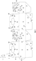
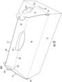
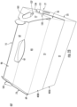
- Fig. 1 is a plan view of the exterior side 1 of a blank, generally indicated at 3, that can be obtained and used to form a carton 5 ( Fig. 4 ) according to a first exemplary embodiment of the invention.
- the carton 5 can engage and be secured to at least one other carton 5 via locking features 133, 135 to form a carton system or system 137 ( Fig. 9 ) of stacked cartons 5.
- the blank 3 has a longitudinal axis L1 and a lateral axis L2.
- the blank 3 comprises a front panel 21 foldably connected to a first side panel 23 and a second side panel 25 at respective lateral fold lines 27, 29.
- a back panel 31 is foldably connected to the first side panel 23 at a lateral fold line 33, and an attachment flap 35 is foldably connected to the back panel 31 at a lateral fold line 37.
- a locking flap 39 (broadly, "first locking flap”) is foldably connected to the first side panel 23 at a fold line 41 and is separable from the first side panel 23 along a line of weakening 43.
- a locking flap 45 (broadly, “second locking flap”) is foldably connected to the second side panel 25 at a fold line 47 and is separable from the second side panel 25 along a line of weakening 49.
- the lines of weakening 43, 49 can extend past the respective locking flaps 39, 45 to form relief tears or relief features in the respective side panels 23, 25.
- a first bottom end flap 51 is foldably connected to the front panel 21 at a portion of a longitudinal fold line 53
- a second bottom end flap 55 is foldably connected to the first side panel 23 at a portion of the longitudinal fold line 53
- a third bottom end flap 57 is foldably connected to the second side panel 25 at a portion of the longitudinal fold line 53
- a fourth bottom end flap 59 is foldably connected to the back panel 31 at a portion of the longitudinal fold line 53.
- marginal tabs 61, 63 are foldably connected to the respective bottom end flaps 51, 59 at respective oblique fold lines 65, 67.
- respective notches 66, 68 are formed along the respective bottom end flaps 51, 59, and can facilitate formation of the carton 5 ( Fig. 4 ), as described further herein.
- a first top end flap 69 is foldably connected to the front panel 21 at a longitudinal fold line 71
- a second top end flap 73 (broadly, “first top end flap” or “third top end flap”) is foldably connected to the first side panel 23 at a longitudinal fold line 75
- a third top end flap 77 (broadly, “second top end flap” or “fourth top end flap”) is foldably connected to the second side panel 25 at a longitudinal fold line 79
- a fourth top end flap 81 is foldably connected to the back panel 31 at a longitudinal fold line 83.
- the first top end flap 69 includes a base portion 85 that is foldably connected to the front panel 21 at the fold line 71 and that is foldably connected to a handle portion 87 at a longitudinal fold line 89.
- the fourth top end flap 81 includes a base portion 91 that is foldably connected to the back panel 31 at the longitudinal fold line 83 and includes a handle portion 93 that is foldably connected to the base portion 91 at a longitudinal fold line 95.
- the top end flap 69 includes a handle opening 97 in portions of the base portion 85 and the handle portion 87 and which interrupts the fold line 89.
- the top end flap 81 includes a handle opening 99 in portions of the base portion 91 and the handle portion 93 and which interrupts the fold line 95.
- the handle portions 87, 93 of the respective top end flaps 69, 81 each include a respective pair of handle tabs 101, 103 at least partially defined by respective notches 105, 107.
- a respective locking tab 109, 111 (broadly, “first locking tab” and “second locking tab”, respectively) is foldably connected to the respective top end flaps 73, 77 at respective longitudinal fold lines 113, 115.
- the locking tabs 109, 111 each have respective flange portions 117, 119 that extend laterally away from the respective fold lines 113, 115 such that a respective pair of engagement notches 121, 123 are formed between the respective locking tabs 109, 111 and the remainder of the respective top end flaps 73, 77.
- Each top end flap 73, 77 also includes a respective aperture 125, 127, as shown.
- the locking tabs 109, 111 of a carton 5 can be inserted into respective openings 134 between the respective locking flaps 39, 45 and the respective side panels 23, 25 of another carton 5 to secure multiple cartons 5 to each other in a system 137 ( Fig. 9 ).
- the locking tabs 109, 111 and the respective locking flaps 39, 45 and associated features form respective locking features 133, 135 of the carton 5.
- the panels 21, 23, 25, 31, the flaps 35, 51, 55, 57, 59, 69, 73, 77, 81, and/or other portions of the blank 3 may be otherwise shaped or configured without departing from the scope of the invention as defined by the appended claims.
- the attachment flap 35 can be positioned into at least partial face-to-face contact with the second side panel 25, for example, via folding of the first side panel 23 at the fold line 27, and can be secured thereto with an adhesive such as glue.
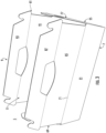
- the front panel 21, the first side panel 23, the second side panel 25, the back panel 31, and the attachment flap 35 can be folded at fold lines 27, 29, 33, 37 such that the front and back panels 21, 31 are substantially parallel to one another and the side panel 23 is substantially parallel to the second side panel 25 and the attachment flap 35.
- the end flaps 51, 55, 57, 59 can be folded at respective portions of the fold line 53 in overlapping relation to form a closed bottom 7 of the carton 5.
- the marginal tabs 61, 63 can be provided with adhesive and in at least partial face-to-face contact with the respective bottom end flaps 57, 55, and the notches 66, 68 of the respective bottom end flaps 51, 59 can interengage one another.
- the marginal tabs 61, 63 can provide connectivity among the end flaps 51, 55, 57, 59 such that the bottom 7 is flexibly reconfigurable between a flattened arrangement and the upwardly-folded arrangement illustrated in Fig. 3 .
- Fig. 3 In the configuration of Fig.
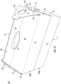
- a top portion 9 of the carton 5 is shown in an open configuration in which the interior 11 of the carton 5 is accessible, for example to load the carton 5 with one or more articles, for example, one or more food products that can be provided, for example, in an unwrapped configuration or wrapped in a secondary packaging, or to retrieve one or more articles from the carton 5.
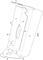
- a first closed configuration of the carton 5A in a first closed configuration of the carton 5, generally designated 5A, the top end flaps 69, 81 can be folded at the respective fold lines 71, 83 toward the interior 11 of the carton 5 and disposed in overlapping, e.g., generally planar, relation such that a closed top portion 9A of the carton 5A (broadly, "first carton") formed by the top end flaps 69, 81 has a first closed configuration with a substantially flat or low profile configuration, as shown.
- first carton a closed top portion 9A of the carton 5A (broadly, "first carton") formed by the top end flaps 69, 81 has a first closed configuration with a substantially flat or low profile configuration, as shown.
- the top end flaps 73, 77 of the carton 5A are maintained in a generally upright position relative to the remainder of the carton 5A such that a receiving space 13 for one or more other cartons is defined on the closed top portion 9A between the top end flaps 73, 77, as described further herein.
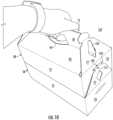
- the carton 5 is shown in a second closed configuration that is generally designated 5B (broadly, "second carton") and having a closed top portion 9B in a second closed configuration.
- 5B broadly, "second carton”
- the carton 5B and the closed top portion 9B will be described herein as one reconfigurable configuration of the carton 5 and top portion 9, and that these terms can be used interchangeably.
- the top portion 9 is reconfigurable between the first closed configuration 9A and the second closed configuration 9B.
- the base portions 85, 91 of the respective top end flaps 69, 81 are folded at the respective fold lines 71, 83 to be obliquely disposed relative to each other and the handle portions 87, 93 of the respective top end flaps 69, 81 are folded upwardly at the respective fold lines 89, 95 relative to the respective base portions 85, 91 such that the handle portions 87, 93 are in at least partial face-to-face contact.
- the handle portions 87, 93 can be obliquely disposed relative to one another. As also shown in Fig.
- the top end flaps 73, 77 are folded at the respective fold lines 75, 79 so that the respective pairs of handle tabs 101, 103 are at least partially inserted through the respective apertures 125, 127 such that the portions of the respective top end flaps 73, 77 surrounding the respective apertures 125, 127 are disposed in the respective notches 105, 107.
- a handle 15 is formed by portions of the top end flaps 69, 73, 77, 81, and can be at least partially grasped by a user through the aligned handle openings 97, 99.
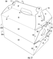
- the carton 5A is shown along with the carton 5B.
- the carton 5B having the upright handle 15 can be positioned in the receiving space 13 of the carton 5A with the substantially flat closed top portion 9A.
- the carton 5B is disposed with its respective side panels 23, 25 in facing relation with the respective top end flaps 73, 77 of the carton 5A, as shown.
- the receiving space 13 of the carton 5A provides an at least partial engagement of the carton 5B via the top end flaps 73, 77 when the carton 5B is positioned in the receiving space 13 of the carton 5A.
- the receiving space 13 of the carton 5A can alternatively receive another carton 5A.
- the respective locking tabs 109, 111 of the respective top end flaps 73, 77 of the lower carton 5A can be inserted through respective openings 134 between the respective locking flaps 39, 45 and the respective side panels 23, 25 of the upper carton 5B.
- the locking flaps 39, 45 of the upper carton 5B can be folded interiorly at the respective fold lines 41, 47 and separated from the respective side panels 23, 25 at the respective lines of weakening 43, 49.
- the respective flange portions 117, 119 of the respective locking tabs 109, 111 of the lower carton 5A can engage an interior portion of the respective side panels 23, 25 of the upper carton 5B.
- the engagement of the respective locking tabs 109, 111 of the lower carton 5A with the respective openings 134 created by the respective locking flaps 39, 45 of the upper carton 5B forms locking features 133, 135 of a system 137 that includes two or more stacked cartons 5A/5B engaged and secured to one another through the locking features 133, 135.
- the upper carton 5B provides the handle 15 by which the entire system 137 can be carried by a user, for example, since the one or more cartons 5A below the upper carton 5B are secured to the upper carton 5B through the locking features 133, 135.
- the system 137 typically includes an upper carton 5B providing the handle 15, and one or more lower cartons 5 A secured to the upper carton 5 and each other through respective locking features 133, 135.
- a system can include two or more stacked cartons 5A and secured to each other with respective locking features 133, 135, without a carton 5B.
- a carton 5A in the first closed configuration can receive a plurality of smaller cartons 5A/5B in its receiving space 13.
- the engagement and securing or locking of multiple cartons 5 to one another in the system 137 as described herein provides a convenient, unitary structure through which more food products can be stored and carried, for example, as compared to a single carton 5. Further, the reconfiguration of the top portion 9 of the carton 5 between the first closed configuration (closed top portion 9A of carton 5A) in which the top portion 9 is flat and the second closed configuration (closed top portion 9B of carton 5B) in which the handle 15 is provided allows each carton 5 in the system 137 to be selectively reconfigurable as the uppermost or a lower carton 5 in the system 137. While the system 137 has been described herein as including two cartons 5, in embodiments, more than two cartons 5 secured to one another with locking features 133, 1 35 can form the system 137.
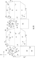
- a blank 203 for forming a carton according to a second exemplary embodiment of the disclosure is illustrated.
- the second exemplary embodiment of the disclosure is similar to the first exemplary embodiment except that the front and back panels 21, 31 of the blank 203 are longer than the front and back panels 21, 31 of the blank 3, and like or similar reference numbers are indicated throughout the drawings to indicate like or similar features.
- the front and back panels 21, 31 of the blank 203 have a length of about 26,67 cm ( ⁇ 10.5 inches) along the longitudinal axis L1
- the front and back panels 21, 31 of the blank 103 ( Fig. 1 ) have a length of about 19,05 cm ( ⁇ 7.5 inches) along the longitudinal axis L1.
- the blank 203 can be used to form cartons 205A, 205B (broadly, "first carton” and “second carton", respectively) having similar configurations to the cartons 5A, 5B ( Fig. 6 ) of the first embodiment described above, and which can be reconfigured and/or secured to one or more other cartons 205A/205B to form a carton system or system 237 similar to the system 137 ( Fig. 9 ) of the first embodiment described above. It will be understood that the cartons 205A, 205B described herein are different configurations of a carton formed from the blank 203.
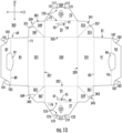
- FIG. 13 an exterior surface 301 of a blank 303 for forming a carton 305 ( Fig. 14 ) according to a third exemplary embodiment of the invention is illustrated.
- the third exemplary embodiment of the invention includes one or more features that are similar to those of the first and second exemplary embodiments of the invention, and similar or identical reference numbers are used to designate identical or similar features.
- the carton 305 includes a leak-resistant bottom receptacle 312 that is substantially devoid of adhered or otherwise coupled surfaces, openings, or other discontinuities.
- the blank 303 includes a bottom panel 320 and a front panel 321 and a back panel 331 foldably connected to the bottom panel 320 at respective lateral fold lines 327, 329.
- the first side panel 23 is foldably connected to the bottom panel 320 at a longitudinal fold line 333 and the second side panel 25 is foldably connected to the bottom panel 320 at a longitudinal fold line 337.
- the blank 303 includes the top end flaps 69, 73, 77, 81 and the locking flaps 39, 45 having substantially similar features to those described above with respect to the first and second exemplary embodiments.
- the illustrated blank 303 also includes a first gusset 339 foldably connected to each of the front panel 321 and the first side panel 23, a second gusset 341 foldably connected to each of the first side panel 23 and the back panel 331, a third gusset 343 foldably connected to each of the back panel 331 and the second side panel 325, and a fourth gusset 345 foldably connected to each of the second side panel 25 and the front panel 321.
- the first gusset 339 includes a first gusset panel 347 foldably connected to the front panel 321 at a portion of the longitudinal fold line 333 and a second gusset panel 349 foldably connected to the first gusset panel 347 at an oblique fold line 351 and foldably connected to the first side panel 23 at a portion of the lateral fold line 327.
- the second gusset 341 includes a third gusset panel 353 foldably connected to the first side panel 23 at a portion of the lateral fold line 329 and a fourth gusset panel 355 foldably connected to the third gusset panel 353 at an oblique fold line 357 and foldably connected to the back panel 331 at a portion of the longitudinal fold line 333.
- the third gusset 343 includes a fifth gusset panel 359 foldably connected to the second side panel 25 at a portion of the lateral fold line 329 and a sixth gusset panel 361 foldably connected to the fifth gusset panel 359 at an oblique fold line 363 and foldaby connected to the back panel 331 at a portion of the longitudinal fold line 337.
- the fourth gusset 345 includes a seventh gusset panel 365 foldably connected to the front panel 321 at a portion of the longitudinal fold line 337 and an eighth gusset panel 367 foldably connected to the seventh gusset panel 365 at an oblique fold line 369 and foldably connected to the second side panel 25 at a portion of the lateral fold line 327.
- the panels 321, 23, 331, 25 can be folded upright relative to the bottom panel 320 to partially form the interior 11 of the carton 305.
- the front panel 321 is folded at the fold line 327 into a generally upright position relative to the bottom panel 320
- the back panel 331 is folded at the fold line 329 into a generally upright position relative to the bottom panel 320
- the respective first and second side panels 23, 25 are folded at the respective fold lines 333, 337 into a generally upright position relative to the bottom panel 320.
- the first gusset panel 347 can be folded at the fold line 351 into at least partial face-to-face contact with the second gusset panel 349, and the second gusset panel 349 can be folded at the fold line 327 into at least partial face-to-face contact with the first side panel 23.
- folding of the second gusset panel 349 at the fold line 327 can draw the front panel 321 into generally intersecting relation with the first side panel 23.
- the fourth gusset panel 355 can be folded at the fold line 357 into at least partial face-to-face contact with the third gusset panel 353, and the third gusset panel 353 can be folded at the fold line 329 into at least partial face-to-face contact with the first side panel 23.
- folding of the third gusset panel 353 at the fold line 329 can draw the back panel 331 into generally intersecting relation with the first side panel 23.
- the sixth gusset panel 361 can be folded at the fold line 363 into at least partial face-to-face contact with the fifth gusset panel 359, and the fifth gusset panel 359 can be folded at the fold line 329 into at least partial face-to-face contact with the second side panel 25.
- folding of the fifth gusset panel 359 at the fold line 329 can draw the back panel 331 into generally intersecting relation with the second side panel 25.
- the seventh gusset panel 365 can be folded at the fold line 369 into at least partial face-to-face contact with the eighth gusset panel 367, and the eighth gusset panel 367 can be folded at the fold line 327 into at least partial face-to-face contact with the second side panel 25.
- folding of the eighth gusset panel 367 at the fold line 327 can draw the front panel 321 into generally intersecting relation with the second side panel 25.
- the gussets 339, 341, 343, 345 can be maintained in the above-described arrangements with one or more adhesives such as glue.
- the above-described arrangement of the panels 321, 331, 23, 25 and the gussets 339, 341, 343, 345 provides an open configuration of the carton 305 in which the interior 11 of the carton 305 is accessible.
- the arrangement of the gussets 339, 341, 343, 345 between the respective panels 321, 23, 331, 25 provides a substantially leak-resistant bottom receptacle 312 that is substantially devoid of adhered or otherwise coupled surfaces, openings, or other discontinuities.
- the front panel 321, the first gusset panel 347, the second gusset panel 349, the first side panel 23, the third gusset panel 353, the fourth gusset panel 355, the back panel 331, the sixth gusset panel 361, the fifth gusset panel 359, the second side panel 25, the eighth gusset panel 367, and the seventh gusset panel 365 (all of which are foldably connected to the bottom panel 320), provide a substantially continuous surface that at least partially forms the bottom receptacle 312 that is joined only by respective fold lines 333, 351 327, 329, 357, 333, 337, 363, 329, 327, 369, 337 such that the panels 321, 347, 349, 23, 353, 355, 331, 361, 359, 25, 367, 365 together with the bottom panel 320, can maintain one or more fluids in the bottom receptacle 312 and inhibit, minimize, and/or
- the bottom receptacle 312 provides a substantially leak-proof or leak-resistant configuration.
- the blank 303/carton 305 can be provided with an interior liner suitable for contact with one or more fluids and arranged to inhibit, minimize, and/or prevent the passage of such one more fluids therethrough, for example, a polymeric material. Such material and/or properties can also be applied to the blank 303/carton 305 as a surface treatment or coating.
- the top portion 9 of the carton 305 can be closed into respective first and second closed top portions 9A, 9B of respective 305A, 305B (broadly, "first carton” and "second carton", respectively) in the manner described above with respect to the cartons 5A, 5B, 205A, 205B ( Figs. 6 , 12 ).
- the carton 305A has the receiving space 13 to receive another carton 305A or a carton 305B to form a carton system or system 338 of cartons 305A, 305B that are engaged with and secured to each other with respective locking features 133, 135 similar to the systems 137, 237 ( Fig.
- cartons 305A, 305B of the system 338 each have a bottom receptacle 312 that provides a substantially leak-proof or leak-resistant configuration to each carton 305 of the system 338. It will be understood that the cartons 305A, 305B are described herein as different configurations of the carton 305 (having respective closed top portions 9A, 9B), and that these terms can be used interchangeably.
- a blank 403 for forming a carton 405 ( Fig. 20 ) according to a fourth exemplary embodiment of the invention is illustrated.
- the fourth exemplary embodiment of the invention includes one or more features that are similar to those of the first, second, and third exemplary embodiments of the invention, and similar or identical reference numbers are used to designate identical or similar features.
- the carton 405 includes a divider flap 457 that is positionable to partition an interior 11 of the carton 405.
- the illustrated blank 403 includes the first side panel 23, the second side panel 25, the front panel 21, the back panel 31, and the attachment flap 35. As shown, the second side panel 25 is foldably connected to the attachment flap 35 at the lateral fold line 29, and the front panel 21 is disposed along a free edge portion of the blank 403.
- the blank 403 also includes the top end flaps 69, 73, 77, 81 and the locking flaps 39, 45 having substantially similar features to those described above with respect to the first, second, and third exemplary embodiments, as well as the bottom end flaps 51, 59 and marginal tabs 61, 63 having substantially similar features to those described above with respect to the first and second exemplary embodiments.
- a bottom end flap 455 is foldably connected to the first side panel 23 at a portion of the longitudinal fold line 53 and a bottom end flap 457 is foldably connected to the second side panel 25 at a portion of the longitudinal fold line 53.
- the bottom end flap 457 includes a proximal section 459 foldably connected to the second side panel 25 at the longitudinal fold line 53 and a distal section 461 foldably connected to the proximal section 459 at a longitudinal fold line 463.
- the attachment flap 35 can be positioned into at least partial face-to-face contact with the back panel 31, for example, via folding of the back panel 31 at the fold line 33 and folding of the second side panel 25 at the fold line 37, and can be secured thereto with an adhesive such as glue.
- the front panel 21, the first side panel 23, the second side panel 25, the back panel 31, and the attachment flap 35 can be folded at fold lines 27, 29, 33, 37 such that the front and back panels 21, 31 are substantially parallel to one another and the side panel 23 is substantially parallel to the second side panel 25 and the attachment flap 35.
- the bottom end flaps 51, 455, 457, 59 can be folded at respective portions of fold line 53 in overlapping relation to form a closed bottom 407 of the carton 405.
- the notches 66, 68 of the respective bottom end flaps 51, 59 interengage one another, the bottom end flap 455 overlaps the bottom end flaps 51, 59, and the bottom end flap 457 overlaps the bottom end flap 455.
- the closed bottom 407 is formed such that the distal section 461 of the bottom end flap 457 can be folded upwardly at the fold line 463 into a generally upright position in the interior 11 of the carton 405.
- the upright positioning of the distal section 461 of the bottom end flap 457 can be maintained, for example, through frictional engagement of an edge of the distal section 461 with the front panel 21 and/or the back panel 31.
- the interior 11 of the carton 405 can be partitioned by the distal section 461 of the bottom end flap 457 into a first interior section 11a and a second interior section 11b on either side of the distal section 461 of the bottom end flap 457, for example, to provide separation of different food products and/or to apportion one or more food products.
- one or both of the first interior section 11a and the second interior section 11b can be used to provide an accessory or condiment for a food product such that one or both of the first interior section 11a and the second interior section 11b can provide a serving tray.
- the distal section 461 of the bottom end flap 457 can optionally be positioned in a substantially flat or planar position relative to the remainder of the closed bottom 407 such that no partitioning of the interior 11 of the carton 405 is provided.
- the top portion 9 of the carton 405 can be closed into respective first and second closed top portions 9A, 9B of respective cartons 405A, 405B (broadly, "first carton” and “second carton", respectively) in the manner described above with respect to the cartons 5A, 5B, 205A, 205B, and 305A, 305B ( Figs. 6 , 12 , 17 ).
- the carton 405A can have the receiving space 13 to receive a carton 405B to form a carton system or system 437 of cartons 405A, 405B that are secured to each other with respective locking features 133, 135 similar to the systems 137, 237, 338 ( Figs.
- the cartons according to the present disclosure can be, for example, formed from blanks of coated paperboard and similar materials.
- the interior and/or exterior sides of the blanks can be coated with a clay coating.
- the clay coating may then be printed over with product, advertising, price coding, and other information or images.
- the blanks may then be coated with a varnish to protect any information printed on the blank.
- the blanks may also be coated with, for example, a moisture barrier layer, on either or both sides of the blank.
- the blanks may be constructed of paperboard of a caliper such that it is heavier and more rigid than ordinary paper.
- the blanks can also be constructed of other materials, such as cardboard, hard paper, or any other material having properties suitable for enabling the carton to function at least generally as described herein.
- the blanks can also be laminated or coated with one or more sheet-like materials at selected panels or panel sections.
- a fold line can be any substantially linear, although not necessarily straight, form of weakening that facilitates folding therealong. More specifically, but not for the purpose of narrowing the scope of the present invention, fold lines include: a score line, such as lines formed with a blunt scoring knife, or the like, which creates a crushed portion in the material along the desired line of weakness; a cut that extends partially into a material along the desired line of weakness, and/or a series of cuts that extend partially into and/or completely through the material along the desired line of weakness; and various combinations of these features.
- a score line such as lines formed with a blunt scoring knife, or the like, which creates a crushed portion in the material along the desired line of weakness
- a cut that extends partially into a material along the desired line of weakness, and/or a series of cuts that extend partially into and/or completely through the material along the desired line of weakness; and various combinations of these features.
- a tear line can include: a slit that extends partially into the material along the desired line of weakness, and/or a series of spaced apart slits that extend partially into and/or completely through the material along the desired line of weakness, or various combinations of these features.
- one type tear line is in the form of a series of spaced apart slits that extend completely through the material, with adjacent slits being spaced apart slightly so that a nick (e.g., a small somewhat bridging-like piece of the material) is defined between the adjacent slits for typically temporarily connecting the material across the tear line. The nicks are broken during tearing along the tear line.
- the nicks typically are a relatively small percentage of the tear line, and alternatively the nicks can be omitted from or torn in a tear line such that the tear line is a continuous cut line. That is, it is within the scope of the present disclosure for each of the tear lines to be replaced with a continuous slit, or the like.
- a cut line can be a continuous slit or could be wider than a slit without departing from the present invention as defined by the appended claims.
- the above embodiments may be described as having one or more panels, flaps, or features, adhered together by glue during erection of the carton embodiments.
- glue is intended to encompass all manner of adhesives commonly used to secure carton panels in place.
Landscapes
- Engineering & Computer Science (AREA)
- Mechanical Engineering (AREA)
- Cartons (AREA)
Claims (22)
- Carton (5, 5A, 5B, 205A, 205B, 305, 305A, 305B, 405, 405A, 405B) destine à contenir un ou plusieurs articles, le carton (5, 5A, 5B, 205A, 205B, 305, 305A, 305B, 405, 405A, 405B) comprenant :une pluralité de panneaux s'étendant au moins partiellement autour d'un intérieur (11) du carton (5, 5A, 5B, 205A, 205B, 305, 305A, 305B, 405, 405A, 405B), la pluralité de panneaux comprenant un panneau avant (21, 321), un panneau arrière (31, 331), un premier panneau latéral (23) et un deuxième panneau latéral (25) ;une pluralité de rabats terminaux reliés à des panneaux respectifs de la pluralité de panneaux et formant une partie supérieure fermée (9, 9A, 9B) du carton (5, 5A, 5B, 205A, 205B, 305, 305A, 305B, 405, 405A, 405B), la pluralité de rabats terminaux comprenant un premier rabat terminal supérieur (73) relié de façon pliable au premier panneau latéral (23) et un deuxième rabat terminal supérieur (77) relié de façon pliable au deuxième panneau latéral (25), la partie supérieure fermée (9, 9A, 9B) du carton (5, 5A, 5B, 205A, 205B, 305, 305A, 305B, 405, 405A, 405B) étant reconfigurable entre une première configuration présentant un profil substantiellement plat et une deuxième configuration formant une poignée (15) du carton (5, 5A, 5B, 205A, 205B, 305, 305A, 305B, 405, 405A, 405B) ; etdes éléments de verrouillage (133, 135) destinés à engager au moins un autre carton (5, 5A, 5B, 205A, 205B, 305, 305A, 305B, 405, 405A, 405B), caractérisé en ce que les éléments de verrouillage (133, 135) comprennent un première patte de verrouillage (109) reliée de façon pliable au premier rabat terminal supérieur (73), une deuxième patte de verrouillage (111) reliée de façon pliable au deuxième rabat terminal supérieur (77), un premier rabat de verrouillage (39) relié de façon pliable au premier panneau latéral (23), et un deuxième rabat de verrouillage (45) relié de façon pliable au deuxième panneau latéral (25), dans lequel chacune parmi la première patte de verrouillage (109) et la deuxième patte de verrouillage (111) présente des parties de rebord (117, 119) respectives, lesquelles s'étendent latéralement à distance de lignes de pliage (113, 115) respectives, de manière à former une paire respective d'encoches d'engagement (121, 123) entre les pattes de verrouillage (109, 111) respectives et le reste des rabats terminaux supérieurs (73, 77), et les pattes de verrouillage (109, 111) sont configurées pour pouvoir être insérées dans des ouvertures (134) respectives entre les rabats de verrouillage (39, 45) respectifs et les panneaux latéraux (23, 25) respectifs d'un autre carton afin de fixer une multitude de cartons les uns aux autres dans un système (13).
- Carton (5, 5A, 5B, 205A, 205B, 305, 305A, 305B, 405, 405A, 405B) selon la revendication 1, dans lequel la pluralité de rabats terminaux supérieurs comprend un troisième rabat terminal supérieur (69) relié de façon pliable au panneau avant (21, 321) et un quatrième rabat terminal supérieur (81) relié de façon pliable au panneau arrière (31, 331), chacun parmi le troisième rabat terminal supérieur (69) et le quatrième rabat terminal supérieur (81) comprend une partie de base (85, 91) respective reliée de façon pliable à une partie de poignée (87, 93) respective.
- Carton (5, 5A, 5B, 205A, 205B, 305, 305A, 305B, 405, 405A, 405B) selon la revendication 2, dans lequel chacun parmi le troisième rabat terminal supérieur (69) et le quatrième rabat terminal supérieur (81) comprend une ouverture de poignée (97, 99) respective disposée dans une partie de l'une au moins parmi la partie de base (85, 91) respective et la partie de poignée (87, 93) respective.
- Carton (5, 5A, 5B, 205A, 205B, 305, 305A, 305B, 405, 405A, 405B) selon la revendication 2, dans lequel, dans la première configuration de la partie supérieure fermée (9, 9A, 9B), le troisième rabat terminal supérieur (69) et le quatrième rabat terminal supérieur (81) sont dans une relation chevauchante, généralement planaire,et dans lequel, dans la première configuration de la partie supérieure fermée (9, 9A, 9B), chacun parmi le premier rabat terminal supérieur (73) et le deuxième rabat terminal supérieur (77) est dans une configuration généralement verticale et un espace de réception (13) est défini entre le premier rabat terminal supérieur (73) et le deuxième rabat terminal supérieur (77),dans la deuxième configuration de la partie supérieure fermée (9, 9A, 9B), les parties de base (85, 91) sont disposées de façon oblique l'une par rapport à l'autre et les parties de poignée (87, 93) sont au moins partiellement en contact face à face,chacun parmi le troisième rabat terminal supérieur (69) et le quatrième rabat terminal supérieur (81) comprend une paire respective de pattes de poignée (101, 103) et chacun parmi le premier rabat terminal supérieur (73) et le deuxième rabat terminal supérieur (77) comprend une ouverture (125, 127) respective, et dans lequel, dans la deuxième configuration de la partie supérieure fermée (9, 9A, 9B), chaque patte de poignée (101, 103) est au moins partiellement insérée à travers une ouverture (125, 127) respective.
- Carton (305, 305A, 305B) selon la revendication 1, dans lequel la pluralité de panneaux comprend en outre un panneau inférieur (320), le panneau inférieur (320) étant relié de façon pliable à chacun parmi le panneau avant (321), le panneau arrière (331), le premier panneau latéral (23) et le deuxième panneau latéral (25),comprenant en outre une pluralité de soufflets, la pluralité de soufflets comprenant un premier soufflet (339) relié de façon pliable à chacun parmi le panneau avant (321) et le premier panneau latéral (23), un deuxième soufflet (341) relié de façon pliable à chacun parmi le premier panneau latéral (23) et le panneau arrière (331), un troisième soufflet (343) relié de façon pliable à chacun parmi le panneau arrière (331) et le deuxième panneau latéral (25), et un quatrième soufflet (345) relié de façon pliable à chacun parmi le deuxième panneau latéral (25) et le panneau avant (321),la pluralité de panneaux et la pluralité de soufflets fournissant une surface substantiellement continue formant au moins partiellement un réceptacle inférieur (312) du carton (305, 305A, 305B).
- Carton (405, 405A, 405B) selon la revendication 1, dans lequel la pluralité de rabats terminaux est une pluralité de rabats terminaux supérieurs, le carton (405, 405A, 405B) comprenant en outre une pluralité de rabats terminaux inférieurs reliés de façon pliable à des panneaux respectifs parmi la pluralité de panneaux,
la pluralité de rabats terminaux inférieurs se chevauchent au moins partiellement pour former un fond fermé (407) du carton (405, 405A, 405B), au moins un rabat terminal inférieur parmi la pluralité de rabats terminaux inférieurs comprend une section proximale (459) reliée de façon pliable à une section distale (461), la section distale (461) étant positionnée dans une position généralement verticale à l'intérieur (11) du carton (405, 405A, 405B) pour former une pluralité de sections intérieures (11a, 11b). - Découpe (3, 203, 303, 403) permettant de former un carton (5, 5A, 5B, 205A, 205B, 305, 305A, 305B, 405, 405A, 405B) destiné à contenir un ou plusieurs articles, la découpe (3, 203, 303, 403) comprenant :une pluralité de panneaux destinée à s'étendre au moins partiellement autour d'un intérieur (11) du carton (5, 5A, 5B, 205A, 205B, 305, 305A, 305B, 405, 405A, 405B) formé à partir de la découpe (3, 203, 303, 403), la pluralité de panneaux comprenant un panneau avant (21, 321), un panneau arrière (31, 331), un premier panneau latéral (23) et un deuxième panneau latéral (25) ;une pluralité de rabats terminaux reliés de façon pliable à des panneaux respectifs parmi la pluralité de panneaux, la pluralité de panneaux étant destinés à former une partie supérieure fermée (9, 9A, 9B) du carton (5, 5A, 5B, 205A, 205B, 305, 305A, 305B, 405, 405A, 405B), laquelle est reconfigurable entre une première configuration présentant un profil substantiellement plat et une deuxième configuration formant une poignée (15) du carton (5, 5A, 5B, 205A, 205B, 305, 305A, 305B, 405, 405A, 405B) formé à partir de la découpe (3, 203, 303, 403), la pluralité de rabats terminaux comprenant un premier rabat terminal supérieur (73) relié de façon pliable au premier panneau latéral (23) et un deuxième rabat terminal supérieur (77) relié de façon pliable au deuxième panneau latéral (25) ; etdes éléments de verrouillage (133, 135) destinés à engager au moins un autre carton (5, 5A, 5B, 205A, 205B, 305, 305A, 305B, 405, 405A, 405B) lorsque le carton (5, 5A, 5B, 205A, 205B, 305, 305A, 305B, 405, 405A, 405B) est formé à partir de la découpe (3, 203, 303, 403), caractérisé en ce que les éléments de verrouillage (133, 135) comprennent un première patte de verrouillage (109) reliée de façon pliable au premier rabat terminal supérieur (73), une deuxième patte de verrouillage (111) reliée de façon pliable au deuxième rabat terminal supérieur (77), un premier rabat de verrouillage (39) relié de façon pliable au premier panneau latéral (23), et un deuxième rabat de verrouillage (45) relié de façon pliable au deuxième panneau latéral (25), dans laquelle chacune parmi la première patte de verrouillage (109) et la deuxième patte de verrouillage (111) présente des parties de rebord (117, 119) respectives, lesquelles s'étendent latéralement à distance de lignes de pliage (113, 115) respectives, de manière à former une paire respective d'encoches d'engagement (121, 123) entre les pattes de verrouillage (109, 111) respectives et le reste des rabats terminaux supérieurs (73, 77), et les pattes de verrouillage (109, 111) sont configurées pour pouvoir être insérées dans des ouvertures (134) respectives entre les rabats de verrouillage (39, 45) respectifs et les panneaux latéraux (23, 25) respectifs d'un autre carton afin de fixer une multitude de cartons les uns aux autres dans un système (13).
- Découpe (3, 203, 303, 403) selon la revendication 7, dans laquelle la pluralité de rabats terminaux comprend un troisième rabat terminal supérieur (69) relié de façon pliable au panneau avant (21, 321) et un quatrième rabat terminal supérieur (81) relié de façon pliable au panneau arrière (31, 331).
- Découpe (3, 203, 303, 403) selon la revendication 8, dans laquelle chacun parmi le troisième rabat terminal supérieur (69) et le quatrième rabat terminal supérieur (81) comprend une partie de base (85, 91) reliée de façon pliable à une partie de poignée (87, 93), chacun parmi le troisième rabat terminal supérieur (69) et le quatrième rabat terminal supérieur (81) comprend une ouverture de poignée (97, 99) respective disposée dans une partie de l'une au moins parmi la partie de base (85, 91) et la partie de poignée (87, 93) respectives.
- Découpe (3, 203, 303, 403) selon la revendication 8, dans laquelle, dans la première configuration de la partie supérieure fermée (9, 9A, 9B) du carton (5, 5A, 5B, 205A, 205B, 305, 305A, 305B, 405, 405A, 405B) formé à partir de la découpe (3, 203, 303, 403), le troisième rabat terminal supérieur (69) et le quatrième rabat terminal supérieur (81) sont dans une relation chevauchante, généralement planaire.
- Découpe (3, 203, 303, 403) selon la revendication 10, dans laquelle, dans la première configuration de la partie supérieure fermée (9, 9A, 9B) du carton (5, 5A, 5B, 205A, 205B, 305, 305A, 305B, 405, 405A, 405B) formé à partir de la découpe (3, 203, 303, 403), chacun parmi le premier rabat terminal supérieur (73) et le deuxième rabat terminal supérieur (77) est dans une configuration généralement verticale et un espace de réception (13) est défini entre le premier rabat terminal supérieur (73) et le deuxième rabat terminal supérieur (77),
chacun parmi le troisième rabat terminal supérieur (69) et le quatrième rabat terminal supérieur (81) comprend une paire respective de pattes de poignée (101, 103) et chacun parmi le premier rabat terminal supérieur (73) et le deuxième rabat terminal supérieur (77) comprend une ouverture (125, 127) respective, et dans laquelle, dans la deuxième configuration de la partie supérieure fermée (9, 9A, 9B) du carton (5, 5A, 5B, 205A, 205B, 305, 305A, 305B, 405, 405A, 405B) formé à partir de la découpe (3, 203, 303, 403), chaque patte de poignée (101, 103) est au moins partiellement insérée à travers une ouverture (125, 127) respective. - Découpe (303) selon la revendication 7, dans laquelle la pluralité de panneaux comprend en outre un panneau inférieur (320), le panneau inférieur (320) étant relié de façon pliable à chacun parmi le panneau avant (321), le panneau arrière (331), le premier panneau latéral (23) et le deuxième panneau latéral (25),comprenant en outre une pluralité de soufflets, la pluralité de soufflets comprenant un premier soufflet (339) relié de façon pliable à chacun parmi le panneau avant (321) et le premier panneau latéral (23), un deuxième soufflet (341) relié de façon pliable à chacun parmi le premier panneau latéral (23) et le panneau arrière (331), un troisième soufflet (343) relié de façon pliable à chacun parmi le panneau arrière (331) et le deuxième panneau latéral (25), et un quatrième soufflet (345) relié de façon pliable à chacun parmi le deuxième panneau latéral (25) et le panneau avant (21, 321),la pluralité de panneaux et la pluralité de soufflets fournissant une surface substantiellement continue formant au moins partiellement un réceptacle inférieur (312) du carton (305, 305A, 305B) formé à partir de la découpe (303).
- Découpe (403) selon la revendication 7, dans laquelle la pluralité de rabats terminaux supérieurs, la découpe (403) comprenant en outre une pluralité de rabats terminaux inférieurs reliés de façon pliable à des panneaux respectifs parmi la pluralité de panneaux,
au moins un rabat terminal inférieur parmi la pluralité de rabats terminaux inférieurs comprend une section proximale (459) reliée de façon pliable à une section distale (461), la section distale (461) étant destinée à être positionnée dans une position généralement verticale à l'intérieur (11) du carton (405, 405A, 405B) formé à partir de la découpe (403) pour former une pluralité de sections intérieures (11a, 11b). - Procédé de formation d'un carton (5, 5A, 5B, 205A, 205B, 305, 305A, 305B, 405, 405A, 405B) destiné à contenir un ou plusieurs articles, le procédé comprenant :l'obtention d'une découpe (3, 203, 303, 403) comprenant une pluralité de panneaux comprenant un panneau avant (21, 321), un panneau arrière (31, 331), un premier panneau latéral (23) et un deuxième panneau latéral (25), la découpe (3, 203, 303, 403) comprenant en outre une pluralité de rabats terminaux reliés de façon pliable à des panneaux respectifs parmi la pluralité de panneaux, la pluralité de rabats terminaux comprenant un premier rabat terminal supérieur (73) relié de façon pliable au premier panneau latéral (23) et un deuxième rabat terminal supérieur (77) relié de façon pliable au deuxième panneau latéral (25), la découpe (3, 203, 303, 403) comprenant en outre des éléments de verrouillage (133, 135) destinés à engager au moins un autre carton (5, 5A, 5B, 205A, 205B, 305, 305A, 305B, 405, 405A, 405B), les éléments de verrouillage (133, 135) comprenant un première patte de verrouillage (109) reliée de façon pliable au premier rabat terminal supérieur (73), une deuxième patte de verrouillage (111) reliée de façon pliable au deuxième rabat terminal supérieur (77), un premier rabat de verrouillage (39) relié de façon pliable au premier panneau latéral (23), et un deuxième rabat de verrouillage (45) relié de façon pliable au deuxième panneau latéral (25) ;le pliage de la pluralité de panneaux au moins partiellement autour d'un intérieur (11) du carton (5, 5A, 5B, 205A, 205B, 305, 305A, 305B, 405, 405A, 405B) ; etle pliage de la pluralité de rabats terminaux pour former une partie supérieure fermée (9, 9A, 9B), la partie supérieure fermée (9, 9A, 9B) du carton (5, 5A, 5B, 205A, 205B, 305, 305A, 305B, 405, 405A, 405B) étant reconfigurable entre une première configuration présentant un profil substantiellement plat et une deuxième configuration formant une poignée (15) du carton (5, 5A, 5B, 205A, 205B, 305, 305A, 305B, 405, 405A, 405B) etdans lequel chacune parmi la première patte de verrouillage (109) et la deuxième patte de verrouillage (111) présente des parties de rebord (117, 119) respectives, lesquelles s'étendent latéralement à distance de lignes de pliage (113, 115) respectives, de manière à former une paire respective d'encoches d'engagement (121, 123) entre les pattes de verrouillage (109, 111) respectives et le reste des rabats terminaux supérieurs (73, 77), et les pattes de verrouillage (109, 111) sont configurées pour pouvoir être insérées dans des ouvertures (134) respectives entre les rabats de verrouillage (39, 45) respectifs et les panneaux latéraux (23, 25) respectifs d'un autre carton afin de fixer une multitude de cartons les uns aux autres dans un système (13).
- Procédé selon la revendication 14, dans lequel la pluralité de rabats terminaux comprend un troisième rabat terminal supérieur (69) relié de façon pliable au panneau avant (21, 321) et un quatrième rabat terminal supérieur (81) relié de façon pliable au panneau arrière (31, 331),
chacun parmi le troisième rabat terminal supérieur (69) et le quatrième rabat terminal supérieur (81) comprend une partie de base (85, 91) respective reliée de façon pliable à une partie de poignée (87, 93) respective. - Procédé selon la revendication 15, dans lequel chacun parmi le troisième rabat terminal supérieur (69) et le quatrième rabat terminal supérieur (81) comprend une ouverture de poignée (97, 99) disposée dans une partie de l'une au moins parmi la partie de base (85, 91) respective et la partie de poignée (87, 93) respective.
- Procédé selon la revendication 15, dans lequel, dans la première configuration de la partie supérieure fermée (9, 9A, 9B), le troisième rabat terminal supérieur (69) et le quatrième rabat terminal supérieur (81) sont dans une relation chevauchante, généralement planaire,dans lequel, dans la première configuration de la partie supérieure fermée (9, 9A, 9B), chacun parmi le premier rabat terminal supérieur (73) et le deuxième rabat terminal supérieur (77) est dans une configuration généralement verticale et un espace de réception (13) est défini entre le premier rabat terminal supérieur (73) et le deuxième rabat terminal supérieur (77),dans la deuxième configuration de la partie supérieure fermée (9, 9A, 9B), les parties de base (85, 91) sont disposées de façon oblique l'une par rapport à l'autre et les parties de poignée (87, 93) sont au moins partiellement en contact face à face,chacun parmi le troisième rabat terminal supérieur (69) et le quatrième rabat terminal supérieur (81) comprend une paire respective de pattes de poignée (101, 103) et chacun parmi le premier rabat terminal supérieur (73) et le deuxième rabat terminal supérieur (77) comprend une ouverture (125, 127) respective, et dans lequel, dans la deuxième configuration de la partie supérieure fermée (9, 9A, 9B), chaque patte de poignée (101, 103) est au moins partiellement insérée à travers une ouverture (125, 127) respective.
- Procédé selon la revendication 14, dans lequel la pluralité de panneaux comprend un panneau inférieur (320), le panneau inférieur (320) étant relié de façon pliable à chacun parmi le panneau avant (321), le panneau arrière (331), le premier panneau latéral (23) et le deuxième panneau latéral (25).
- Procédé selon la revendication 14, comprenant en outre une pluralité de soufflets, la pluralité de soufflets comprenant un premier soufflet (339) relié de façon pliable à chacun parmi le panneau avant (321) et le premier panneau latéral (23), un deuxième soufflet (341) relié de façon pliable à chacun parmi le premier panneau latéral (23) et le panneau arrière (331), un troisième soufflet (343) relié de façon pliable à chacun parmi le panneau arrière (331) et le deuxième panneau latéral (25), et un quatrième soufflet (345) relié de façon pliable à chacun parmi le deuxième panneau latéral (25) et le panneau avant (321),
la pluralité de panneaux et la pluralité de soufflets fournissant une surface substantiellement continue formant au moins partiellement un réceptacle inférieur (312) du carton (305, 305A, 305B). - Procédé selon la revendication 14, dans lequel la pluralité de rabats terminaux est une pluralité de rabats terminaux supérieurs, la découpe (403) comprenant en outre une pluralité de rabats terminaux inférieurs reliés de façon pliable à des panneaux respectifs parmi la pluralité de panneaux,la pluralité de rabats terminaux inférieurs se chevauchant au moins partiellement pour former un fond fermé (407) du carton (405, 405A, 405B),au moins un rabat terminal inférieur parmi la pluralité de rabats terminaux inférieurs comprend une section proximale (459) reliée de façon pliable à une section distale (461), la section distale (461) étant destinée à être positionnée dans une position généralement verticale à l'intérieur (11) du carton (405, 405A, 405B) pour former une pluralité de sections intérieures (11a, 11b) .
- Système (137, 237, 338, 437) comprenant :un premier carton selon l'une quelconque des revendications 1 à 6,un deuxième carton (5B, 205B, 305B, 405B) selon l'une quelconque des revendications 1 à 6, dans lequella première patte de verrouillage (109) du premier carton (51, 205A, 305A, 405A) est au moins partiellement insérée dans une ouverture entre le premier rabat de verrouillage (39) et le premier panneau latéral (23) du deuxième carton (5B, 205B, 305B, 405B) et la deuxième patte de verrouillage (111) du premier carton (51, 205A, 305A, 405A) est au moins partiellement insérée dans une ouverture entre le deuxième rabat de verrouillage (45) et le deuxième panneau latéral (25) du deuxième carton (5B, 205B, 305B, 405B).
- Système (137, 237, 338, 437) selon la revendication 21, dans lequel la pluralité de rabats terminaux du deuxième carton (5B, 205B, 305B, 405B) comprend un troisième rabat terminal supérieur (69) et un quatrième rabat terminal supérieur (81), chacun parmi le troisième rabat terminal supérieur (69) et le quatrième rabat terminal supérieur (81) du deuxième carton (5B, 205B, 305B, 405B) comprend une partie de base (85, 91) respective reliée de façon pliable à une partie de poignée (87, 93) respective,les parties de base (85, 91) du deuxième carton (5B, 205B, 305B, 405B) sont disposées de façon oblique l'une par rapport à l'autre et les parties de poignée (87, 93) du deuxième carton (5B, 205B, 305B, 405B) sont au moins partiellement en contact face à face,chacun parmi le premier rabat terminal supérieur (73) et le deuxième rabat terminal supérieur (77) du deuxième carton (5B, 205B, 305B, 405B) comprend une ouverture (125, 127) respective, dans lequel chacun parmi le troisième rabat terminal supérieur (69) et le quatrième rabat terminal supérieur (81) comprend une paire respective de pattes de poignée (101, 103), et dans lequel chaque patte de poignée (101, 103) est au moins partiellement insérée à travers une ouverture (125, 127) respective.
Applications Claiming Priority (2)
| Application Number | Priority Date | Filing Date | Title |
|---|---|---|---|
| US201762533268P | 2017-07-17 | 2017-07-17 | |
| PCT/US2018/042246 WO2019018265A1 (fr) | 2017-07-17 | 2018-07-16 | Carton comprenant des éléments de verrouillage |
Publications (4)
| Publication Number | Publication Date |
|---|---|
| EP3655337A1 EP3655337A1 (fr) | 2020-05-27 |
| EP3655337A4 EP3655337A4 (fr) | 2021-03-03 |
| EP3655337C0 EP3655337C0 (fr) | 2024-09-04 |
| EP3655337B1 true EP3655337B1 (fr) | 2024-09-04 |
Family
ID=65000613
Family Applications (1)
| Application Number | Title | Priority Date | Filing Date |
|---|---|---|---|
| EP18835444.3A Active EP3655337B1 (fr) | 2017-07-17 | 2018-07-16 | Carton comprenant des éléments de verrouillage, découpe et procédé de fabrication d'un carton |
Country Status (5)
| Country | Link |
|---|---|
| US (1) | US11273950B2 (fr) |
| EP (1) | EP3655337B1 (fr) |
| CA (1) | CA3064787C (fr) |
| ES (1) | ES2992848T3 (fr) |
| WO (1) | WO2019018265A1 (fr) |
Families Citing this family (10)
| Publication number | Priority date | Publication date | Assignee | Title |
|---|---|---|---|---|
| US11053048B2 (en) | 2019-07-24 | 2021-07-06 | Pratt Corrugated Holdings, Inc. | Box with foldable handle |
| USD936476S1 (en) | 2019-07-24 | 2021-11-23 | Pratt Corrugated Holdings, Inc. | Box with foldable handle |
| DE102020110004B4 (de) * | 2020-04-09 | 2024-06-27 | Illinois Tool Works Inc. | Abdeckung für eine druckbegrenzungsventilanordnung eines fahrzeugs, druckbegrenzungsventilanordnung sowie verfahren zur herstellung einer abdeckung für eine druckbegrenzungsventilanordnung |
| IT202000012202A1 (it) * | 2020-05-25 | 2021-11-25 | Artecarta Italia S R L | Scatola per alimenti anti fuoriuscite |
| JP2023542009A (ja) * | 2020-09-18 | 2023-10-04 | ウエストロック シェアード サービシズ、エルエルシー | 積み重ね可能なカートンならびにそれを形成するためのブランクおよび方法 |
| KR102271518B1 (ko) * | 2020-12-10 | 2021-07-01 | 주식회사 나우스 | 저면이 보강된 햄버거세트 딜리버리 포장상자 |
| USD1008797S1 (en) | 2021-06-15 | 2023-12-26 | Andy's Frozen Custard Holdings, LLC | Carton for frozen dessert |
| USD1012692S1 (en) | 2021-06-15 | 2024-01-30 | Andy's Frozen Custard Holdings, LLC | Assembled carton for frozen dessert |
| US20260042569A1 (en) * | 2022-07-28 | 2026-02-12 | Tria Pte. Ltd. | A Food Box |
| US12434879B2 (en) * | 2024-02-26 | 2025-10-07 | Uppercut Box Company | Food service box |
Family Cites Families (95)
| Publication number | Priority date | Publication date | Assignee | Title |
|---|---|---|---|---|
| SE140388C1 (fr) | ||||
| US2348378A (en) | 1942-04-30 | 1944-05-09 | Fibreboard Products Inc | Carton |
| US2586301A (en) | 1950-01-10 | 1952-02-19 | Eli N Castle | Foldable cardboard bottle carrier |
| GB889718A (en) | 1958-04-08 | 1962-02-21 | Shirley And Warbey Box Company | Improvements in cardboard and like boxes |
| US3013710A (en) | 1960-04-08 | 1961-12-19 | Wagner Folding Box Corp | Cardboard tray |
| US3150769A (en) | 1962-09-06 | 1964-09-29 | South River Metal Products Co | Wire packaging and handling device |
| US3257027A (en) | 1962-09-12 | 1966-06-21 | Continental Can Co | Double wall separator for bottle carriers |
| US3640380A (en) | 1969-11-20 | 1972-02-08 | Marketers Inc | Portable food and drink carrier |
| USD242901S (en) | 1975-09-10 | 1977-01-04 | Hoerner Waldorf Corporation | Carrying carton |
| US4007869A (en) | 1976-01-14 | 1977-02-15 | Stolmar Corporation | Corrugated carton constructions |
| NL7805903A (en) * | 1978-05-31 | 1979-12-04 | Drukkerijen Louis Vermijs B V | Cake packaging box - has lid and walls allowing formation of rigid stack with handle at top |
| US4185765A (en) | 1978-07-24 | 1980-01-29 | Champion International Corporation | Hermetic sealed carton |
| US4230261A (en) | 1979-04-16 | 1980-10-28 | Champion International Corporation | Lunch box carton and a blank for forming same |
| US4471094A (en) | 1980-08-29 | 1984-09-11 | Owens-Corning Fiberglas Corporation | Primer composition |
| FR2494668B1 (fr) * | 1980-11-27 | 1986-10-24 | Gault Fremont | Boite portable et empilable |
| US4397393A (en) | 1981-06-09 | 1983-08-09 | The Coca-Cola Company | Fast food carryout package |
| US4530459A (en) | 1983-09-16 | 1985-07-23 | James River - Norwalk, Inc. | Folding carrier carton including split cover closure, removable trays and blanks for making same |
| IT1166957B (it) | 1983-09-20 | 1987-05-06 | Elopak As | Contenitore per liquidi, suo sviluppo e metodo per ottenere detto sviluppo |
| US4535928A (en) | 1983-11-02 | 1985-08-20 | International Paper Company | Dual purpose carton |
| US4498585A (en) | 1983-12-23 | 1985-02-12 | International Paper Company | Denesting paperboard container |
| US4548352A (en) | 1984-01-20 | 1985-10-22 | International Paper Company | Pop-out carton |
| US4580718A (en) | 1984-03-22 | 1986-04-08 | Weyerhaeuser Company | Container with tuck-in closure |
| US4601390A (en) | 1985-01-28 | 1986-07-22 | Roberta Rosenthal | Collapsible hand carrier for bottles |
| DE3641485A1 (de) | 1986-12-04 | 1988-06-09 | Unilever Nv | Taschenfoermige verpackung |
| US4782788A (en) | 1987-08-05 | 1988-11-08 | Domta Inc. | Litter box with handle and blank therefor |
| USD319388S (en) | 1989-06-09 | 1991-08-27 | The C. W. Zumbiel Co. | Beverage can carrier |
| US4969596A (en) | 1989-07-21 | 1990-11-13 | Biosystems Partners | Infectious waste disposal container |
| US5020337A (en) | 1990-01-11 | 1991-06-04 | Krieg David F | Combination ice package and expandable cooler |
| US5042715A (en) | 1990-09-04 | 1991-08-27 | Mcneill Allen | Folding carton |
| US5060850A (en) | 1990-12-05 | 1991-10-29 | Waldorf Corporation | Bag-like folding carton |
| EP0549874A1 (fr) | 1991-12-13 | 1993-07-07 | Societe Des Produits Nestle S.A. | Boîte en carton |
| GB9215257D0 (en) | 1992-07-17 | 1992-09-02 | Riverwood Int Ltd | Container for articles |
| TW264451B (fr) | 1992-07-28 | 1995-12-01 | M Pak Ltd | |
| US5240174A (en) | 1992-08-28 | 1993-08-31 | Eveready Battery Company, Inc. | Environmentally friendly and space efficient battery package |
| DE69410848T2 (de) * | 1993-02-17 | 1998-12-03 | Visual Project S.R.L., Marzabotto, Bologna | Verpackungsbehälter |
| US5275331A (en) | 1993-05-18 | 1994-01-04 | Chung Piao Tsao | Foldable container with one-step unfolding operation |
| FR2708906A1 (fr) | 1993-08-10 | 1995-02-17 | Nicollet Hugues Sa | Procédé pour le conditionnement d'un produit pulvérulent ou granulaire, conteneur pour la mise en Óoeuvre de ce procédé et flan correspondant. |
| USD371965S (en) | 1993-11-01 | 1996-07-23 | Jeff Kinni | Container for pet food |
| US5392984A (en) | 1994-02-08 | 1995-02-28 | Dopaco, Inc. | Carton with reinforced handle |
| US5423478A (en) | 1994-06-07 | 1995-06-13 | International Paper Company | Takeout container with integral handles |
| US5400901A (en) | 1994-06-16 | 1995-03-28 | Riverwood International Corporation | Basket-style carrier with removable handle |
| US5524814A (en) | 1994-11-07 | 1996-06-11 | Davis; Lee | Collapsible container for carry-out foods |
| US5458270A (en) | 1995-01-17 | 1995-10-17 | Tsao; Chung-Piao | Foldable liquid container for preventing leakage |
| US5520284A (en) * | 1995-03-15 | 1996-05-28 | Westvaco Corporation | Auto-bottom front lock carton |
| US5551556A (en) | 1995-06-14 | 1996-09-03 | Riverwood International Corporation | Wrap-around carrier with bar code blocking end panels |
| USD373079S (en) | 1995-09-14 | 1996-08-27 | The Coca-Cola Company | Bottle carrier |
| USD386680S (en) | 1995-09-14 | 1997-11-25 | The Coca-Cola Company | Bottle carrier |
| US5620134A (en) | 1995-11-07 | 1997-04-15 | Gulf States Paper Corporation | Closable carton |
| US5685478A (en) | 1996-03-18 | 1997-11-11 | Tang; Donald | Single piece container and method for making |
| US6116421A (en) | 1996-07-30 | 2000-09-12 | Eastman Kodak Company | Carrier for a package of box-like items |
| JPH10157726A (ja) * | 1996-11-29 | 1998-06-16 | Rengo Co Ltd | 把手付包装箱 |
| USD396805S (en) | 1997-07-09 | 1998-08-11 | Wingate Packaging, Inc. | Disposable lunch box |
| US5853121A (en) | 1997-08-05 | 1998-12-29 | Laminating Technologies, Inc. | Insulated chest |
| US6108982A (en) | 1997-10-21 | 2000-08-29 | Davison; Julie Mcclendon | Folding play structure |
| US6189687B1 (en) | 1997-12-19 | 2001-02-20 | The Mead Corporation | Article carrier and blank therefor |
| USD418751S (en) | 1998-02-15 | 2000-01-11 | David Wolf | Foldable carton with handles |
| US5927593A (en) | 1998-05-08 | 1999-07-27 | Island Container Corporation | Collapsible container |
| US6290123B1 (en) | 1998-10-06 | 2001-09-18 | Inland Paperboard And Packaging, Inc. | Bottom structure for collapsible container |
| US6036085A (en) | 1999-03-05 | 2000-03-14 | Tsao; Chung-Piao | Portable food container having sideward openable access |
| US6189776B1 (en) | 1999-03-26 | 2001-02-20 | Motion Design, Inc. | Nested box with integrated lid and/or support structure for hanging files |
| SG118061A1 (en) * | 1999-12-14 | 2006-01-27 | Boon Wee Lau | A portable and stackable leak-proof container formed from a blank of material |
| USD442859S1 (en) * | 2000-07-11 | 2001-05-29 | Climax Manufacturing Company | Carton |
| DE10061402A1 (de) | 2000-12-09 | 2002-06-13 | Beiersdorf Ag | Wiederverschließbare, quaderförmige Faltschachtel |
| US6439452B1 (en) | 2001-08-24 | 2002-08-27 | Chung-Piao Tsao | Container for separately carrying cold drink and hot foods |
| USD464878S1 (en) | 2001-10-08 | 2002-10-29 | Oneida Ltd. | Package for bridal flatware |
| US6837420B2 (en) * | 2001-11-16 | 2005-01-04 | Wes Pak, Inc. | Foldable portable cooler with enhanced over-center locking handle |
| US6530516B1 (en) | 2001-11-21 | 2003-03-11 | Stone Container Corporation | Self-deploying carton bottom |
| US20030111521A1 (en) | 2001-12-17 | 2003-06-19 | Holmes Gordon W. | Gift packaging and method of manufacture thereof |
| US6581823B1 (en) | 2002-01-29 | 2003-06-24 | Thom De Beck | Pastry tote with handles |
| US6802802B2 (en) | 2002-05-17 | 2004-10-12 | Usi International, Inc. | Beverage carrier |
| USD488062S1 (en) | 2002-10-23 | 2004-04-06 | Schreiber Foods, Inc. | Food carton |
| US20050023331A1 (en) * | 2003-07-30 | 2005-02-03 | Hirschey Urban C. | Two-tiered pastry box |
| US7328814B2 (en) | 2003-10-20 | 2008-02-12 | Pactiv Corporation | Polymeric containers with handle |
| USD497309S1 (en) | 2003-10-20 | 2004-10-19 | Pactiv Corporation | Polymeric container with handle |
| EP1833727A1 (fr) * | 2004-10-28 | 2007-09-19 | Graphic Packaging International, Inc. | Carton a formations de fermeture multiples |
| US7617969B2 (en) | 2005-06-30 | 2009-11-17 | Graphic Packaging International, Inc. | Carton capable of carrying take-out food and beverages |
| USD525866S1 (en) | 2005-06-30 | 2006-08-01 | Graphic Packaging International, Inc. | Carton |
| USD567671S1 (en) | 2007-07-06 | 2008-04-29 | Cajas Y Empaques De Guatemala S.A. | Drink and food tray |
| USD576482S1 (en) | 2007-12-19 | 2008-09-09 | Frankston Packaging Company | Container |
| KR20100001674A (ko) | 2008-06-27 | 2010-01-06 | 윤슬기 | 이동형 홈 네트워크 단말기 |
| CN201284043Y (zh) * | 2008-08-28 | 2009-08-05 | 黄建璋 | 可叠合的纸盒容器 |
| UA21664S (uk) | 2010-03-08 | 2011-04-11 | Брітіш Амерікан | Упаковка для сигарет |
| US20110272458A1 (en) * | 2010-05-04 | 2011-11-10 | Osram Sylvania Inc. | Auto-bottom carton with self-erecting partition |
| USD640128S1 (en) * | 2010-11-30 | 2011-06-21 | Syndicate Sales, Inc. | Cake plate carrier |
| JP2012166813A (ja) * | 2011-02-14 | 2012-09-06 | Yamanaka Nobuyasu | 焼き鳥箱 |
| USD688939S1 (en) * | 2011-08-17 | 2013-09-03 | Union Packaging, LLC | Food container |
| USD760446S1 (en) | 2011-12-13 | 2016-06-28 | Animal Care Equipment & Services, Llc | Convertible animal carrier |
| USD693216S1 (en) | 2012-01-09 | 2013-11-12 | Inno-Pak, Llc | Windowed closeable carton |
| USD674690S1 (en) | 2012-02-27 | 2013-01-22 | Inno-Pak, Llc | Closeable carton |
| USD675520S1 (en) | 2012-03-20 | 2013-02-05 | Inno-Pak, Llc | Closeable carton |
| US20140262911A1 (en) * | 2013-03-12 | 2014-09-18 | Meadwestvaco Corporation | Stackable carrier |
| US9533790B2 (en) * | 2014-08-11 | 2017-01-03 | Southern Champion Tray, Lp | Foldable and stackable barn box |
| US9597851B2 (en) * | 2014-08-22 | 2017-03-21 | Southern Champion Tray, L.P. | Push folding of carton blanks |
| USD758184S1 (en) | 2015-03-13 | 2016-06-07 | TableRunner, LLC | Container for shipping prepared meals |
| USD798142S1 (en) | 2016-05-31 | 2017-09-26 | Falconglen Limited | Produce box |
-
2018
- 2018-07-16 CA CA3064787A patent/CA3064787C/fr active Active
- 2018-07-16 US US16/036,161 patent/US11273950B2/en active Active
- 2018-07-16 EP EP18835444.3A patent/EP3655337B1/fr active Active
- 2018-07-16 ES ES18835444T patent/ES2992848T3/es active Active
- 2018-07-16 WO PCT/US2018/042246 patent/WO2019018265A1/fr not_active Ceased
Also Published As
| Publication number | Publication date |
|---|---|
| WO2019018265A1 (fr) | 2019-01-24 |
| EP3655337C0 (fr) | 2024-09-04 |
| CA3064787C (fr) | 2023-08-29 |
| EP3655337A1 (fr) | 2020-05-27 |
| CA3064787A1 (fr) | 2019-01-24 |
| ES2992848T3 (en) | 2024-12-19 |
| EP3655337A4 (fr) | 2021-03-03 |
| US11273950B2 (en) | 2022-03-15 |
| US20190016500A1 (en) | 2019-01-17 |
Similar Documents
| Publication | Publication Date | Title |
|---|---|---|
| CA3064787C (fr) | Carton comprenant des elements de verrouillage | |
| AU2013240454B2 (en) | Carton with tray | |
| EP2991907B1 (fr) | Carton à éléments pouvant être refermés | |
| EP1855958B1 (fr) | Carton avec des cloisons entrecroisées | |
| US10173805B2 (en) | Reclosable carton | |
| EP3755635B1 (fr) | Cartons empilables, système, et leurs procédés d'utilisation | |
| EP3094566B1 (fr) | Brique alimentaire dotée d'élément d'ouverture | |
| EP3678953B1 (fr) | Carton comprenant au moins un support, découpe et méthode associée | |
| US11548708B2 (en) | Carrier with lid | |
| US20090057384A1 (en) | Carton for dispensing products and method of using the same | |
| US12617595B2 (en) | Sleeve for holding containers | |
| US20250296726A1 (en) | Carton With Insert | |
| US20240067390A1 (en) | Divider Construct For Cartons, Related Systems And Methods |
Legal Events
| Date | Code | Title | Description |
|---|---|---|---|
| STAA | Information on the status of an ep patent application or granted ep patent |
Free format text: STATUS: THE INTERNATIONAL PUBLICATION HAS BEEN MADE |
|
| PUAI | Public reference made under article 153(3) epc to a published international application that has entered the european phase |
Free format text: ORIGINAL CODE: 0009012 |
|
| STAA | Information on the status of an ep patent application or granted ep patent |
Free format text: STATUS: REQUEST FOR EXAMINATION WAS MADE |
|
| 17P | Request for examination filed |
Effective date: 20200211 |
|
| AK | Designated contracting states |
Kind code of ref document: A1 Designated state(s): AL AT BE BG CH CY CZ DE DK EE ES FI FR GB GR HR HU IE IS IT LI LT LU LV MC MK MT NL NO PL PT RO RS SE SI SK SM TR |
|
| AX | Request for extension of the european patent |
Extension state: BA ME |
|
| DAV | Request for validation of the european patent (deleted) | ||
| DAX | Request for extension of the european patent (deleted) | ||
| A4 | Supplementary search report drawn up and despatched |
Effective date: 20210128 |
|
| RIC1 | Information provided on ipc code assigned before grant |
Ipc: B65D 5/36 20060101ALI20210122BHEP Ipc: B65D 5/00 20060101AFI20210122BHEP Ipc: B65D 5/46 20060101ALI20210122BHEP Ipc: B65D 5/24 20060101ALI20210122BHEP Ipc: B65D 5/48 20060101ALI20210122BHEP |
|
| STAA | Information on the status of an ep patent application or granted ep patent |
Free format text: STATUS: EXAMINATION IS IN PROGRESS |
|
| 17Q | First examination report despatched |
Effective date: 20221221 |
|
| GRAP | Despatch of communication of intention to grant a patent |
Free format text: ORIGINAL CODE: EPIDOSNIGR1 |
|
| STAA | Information on the status of an ep patent application or granted ep patent |
Free format text: STATUS: GRANT OF PATENT IS INTENDED |
|
| INTG | Intention to grant announced |
Effective date: 20240306 |
|
| GRAS | Grant fee paid |
Free format text: ORIGINAL CODE: EPIDOSNIGR3 |
|
| GRAA | (expected) grant |
Free format text: ORIGINAL CODE: 0009210 |
|
| STAA | Information on the status of an ep patent application or granted ep patent |
Free format text: STATUS: THE PATENT HAS BEEN GRANTED |
|
| AK | Designated contracting states |
Kind code of ref document: B1 Designated state(s): AL AT BE BG CH CY CZ DE DK EE ES FI FR GB GR HR HU IE IS IT LI LT LU LV MC MK MT NL NO PL PT RO RS SE SI SK SM TR |
|
| REG | Reference to a national code |
Ref country code: GB Ref legal event code: FG4D |
|
| REG | Reference to a national code |
Ref country code: CH Ref legal event code: EP |
|
| REG | Reference to a national code |
Ref country code: IE Ref legal event code: FG4D |
|
| REG | Reference to a national code |
Ref country code: DE Ref legal event code: R096 Ref document number: 602018074071 Country of ref document: DE |
|
| U01 | Request for unitary effect filed |
Effective date: 20240904 |
|
| U07 | Unitary effect registered |
Designated state(s): AT BE BG DE DK EE FI FR IT LT LU LV MT NL PT RO SE SI Effective date: 20240923 |
|
| REG | Reference to a national code |
Ref country code: ES Ref legal event code: FG2A Ref document number: 2992848 Country of ref document: ES Kind code of ref document: T3 Effective date: 20241219 |
|
| PG25 | Lapsed in a contracting state [announced via postgrant information from national office to epo] |
Ref country code: NO Free format text: LAPSE BECAUSE OF FAILURE TO SUBMIT A TRANSLATION OF THE DESCRIPTION OR TO PAY THE FEE WITHIN THE PRESCRIBED TIME-LIMIT Effective date: 20241204 |
|
| PG25 | Lapsed in a contracting state [announced via postgrant information from national office to epo] |
Ref country code: PL Free format text: LAPSE BECAUSE OF FAILURE TO SUBMIT A TRANSLATION OF THE DESCRIPTION OR TO PAY THE FEE WITHIN THE PRESCRIBED TIME-LIMIT Effective date: 20240904 Ref country code: GR Free format text: LAPSE BECAUSE OF FAILURE TO SUBMIT A TRANSLATION OF THE DESCRIPTION OR TO PAY THE FEE WITHIN THE PRESCRIBED TIME-LIMIT Effective date: 20241205 |
|
| PG25 | Lapsed in a contracting state [announced via postgrant information from national office to epo] |
Ref country code: HR Free format text: LAPSE BECAUSE OF FAILURE TO SUBMIT A TRANSLATION OF THE DESCRIPTION OR TO PAY THE FEE WITHIN THE PRESCRIBED TIME-LIMIT Effective date: 20240904 |
|
| PG25 | Lapsed in a contracting state [announced via postgrant information from national office to epo] |
Ref country code: RS Free format text: LAPSE BECAUSE OF FAILURE TO SUBMIT A TRANSLATION OF THE DESCRIPTION OR TO PAY THE FEE WITHIN THE PRESCRIBED TIME-LIMIT Effective date: 20241204 |
|
| PG25 | Lapsed in a contracting state [announced via postgrant information from national office to epo] |
Ref country code: RS Free format text: LAPSE BECAUSE OF FAILURE TO SUBMIT A TRANSLATION OF THE DESCRIPTION OR TO PAY THE FEE WITHIN THE PRESCRIBED TIME-LIMIT Effective date: 20241204 Ref country code: PL Free format text: LAPSE BECAUSE OF FAILURE TO SUBMIT A TRANSLATION OF THE DESCRIPTION OR TO PAY THE FEE WITHIN THE PRESCRIBED TIME-LIMIT Effective date: 20240904 Ref country code: NO Free format text: LAPSE BECAUSE OF FAILURE TO SUBMIT A TRANSLATION OF THE DESCRIPTION OR TO PAY THE FEE WITHIN THE PRESCRIBED TIME-LIMIT Effective date: 20241204 Ref country code: HR Free format text: LAPSE BECAUSE OF FAILURE TO SUBMIT A TRANSLATION OF THE DESCRIPTION OR TO PAY THE FEE WITHIN THE PRESCRIBED TIME-LIMIT Effective date: 20240904 Ref country code: GR Free format text: LAPSE BECAUSE OF FAILURE TO SUBMIT A TRANSLATION OF THE DESCRIPTION OR TO PAY THE FEE WITHIN THE PRESCRIBED TIME-LIMIT Effective date: 20241205 |
|
| PG25 | Lapsed in a contracting state [announced via postgrant information from national office to epo] |
Ref country code: IS Free format text: LAPSE BECAUSE OF FAILURE TO SUBMIT A TRANSLATION OF THE DESCRIPTION OR TO PAY THE FEE WITHIN THE PRESCRIBED TIME-LIMIT Effective date: 20250104 |
|
| PG25 | Lapsed in a contracting state [announced via postgrant information from national office to epo] |
Ref country code: SM Free format text: LAPSE BECAUSE OF FAILURE TO SUBMIT A TRANSLATION OF THE DESCRIPTION OR TO PAY THE FEE WITHIN THE PRESCRIBED TIME-LIMIT Effective date: 20240904 |
|
| PG25 | Lapsed in a contracting state [announced via postgrant information from national office to epo] |
Ref country code: CZ Free format text: LAPSE BECAUSE OF FAILURE TO SUBMIT A TRANSLATION OF THE DESCRIPTION OR TO PAY THE FEE WITHIN THE PRESCRIBED TIME-LIMIT Effective date: 20240904 |
|
| PG25 | Lapsed in a contracting state [announced via postgrant information from national office to epo] |
Ref country code: SK Free format text: LAPSE BECAUSE OF FAILURE TO SUBMIT A TRANSLATION OF THE DESCRIPTION OR TO PAY THE FEE WITHIN THE PRESCRIBED TIME-LIMIT Effective date: 20240904 |
|
| PLBE | No opposition filed within time limit |
Free format text: ORIGINAL CODE: 0009261 |
|
| STAA | Information on the status of an ep patent application or granted ep patent |
Free format text: STATUS: NO OPPOSITION FILED WITHIN TIME LIMIT |
|
| 26N | No opposition filed |
Effective date: 20250605 |
|
| U20 | Renewal fee for the european patent with unitary effect paid |
Year of fee payment: 8 Effective date: 20250728 |
|
| PGFP | Annual fee paid to national office [announced via postgrant information from national office to epo] |
Ref country code: ES Payment date: 20250801 Year of fee payment: 8 |
|
| PGFP | Annual fee paid to national office [announced via postgrant information from national office to epo] |
Ref country code: GB Payment date: 20250728 Year of fee payment: 8 |
|
| REG | Reference to a national code |
Ref country code: CH Ref legal event code: H13 Free format text: ST27 STATUS EVENT CODE: U-0-0-H10-H13 (AS PROVIDED BY THE NATIONAL OFFICE) Effective date: 20260224 |
|
| PG25 | Lapsed in a contracting state [announced via postgrant information from national office to epo] |
Ref country code: CH Free format text: LAPSE BECAUSE OF NON-PAYMENT OF DUE FEES Effective date: 20250731 |