EP3655603B1 - Serrure pour entrée de carburant ou socle de chargement et entrée de carburant ou socle de chargement - Google Patents
Serrure pour entrée de carburant ou socle de chargement et entrée de carburant ou socle de chargement Download PDFInfo
- Publication number
- EP3655603B1 EP3655603B1 EP18750336.2A EP18750336A EP3655603B1 EP 3655603 B1 EP3655603 B1 EP 3655603B1 EP 18750336 A EP18750336 A EP 18750336A EP 3655603 B1 EP3655603 B1 EP 3655603B1
- Authority
- EP
- European Patent Office
- Prior art keywords
- locking
- pin
- ball
- receptacle
- locking device
- Prior art date
- Legal status (The legal status is an assumption and is not a legal conclusion. Google has not performed a legal analysis and makes no representation as to the accuracy of the status listed.)
- Active
Links
Images

Classifications
-
- E—FIXED CONSTRUCTIONS
- E05—LOCKS; KEYS; WINDOW OR DOOR FITTINGS; SAFES
- E05B—LOCKS; ACCESSORIES THEREFOR; HANDCUFFS
- E05B83/00—Vehicle locks specially adapted for particular types of wing or vehicle
- E05B83/28—Locks for glove compartments, console boxes, fuel inlet covers or the like
- E05B83/34—Locks for glove compartments, console boxes, fuel inlet covers or the like for fuel inlet covers essentially flush with the vehicle surface
-
- B—PERFORMING OPERATIONS; TRANSPORTING
- B60—VEHICLES IN GENERAL
- B60K—ARRANGEMENT OR MOUNTING OF PROPULSION UNITS OR OF TRANSMISSIONS IN VEHICLES; ARRANGEMENT OR MOUNTING OF PLURAL DIVERSE PRIME-MOVERS IN VEHICLES; AUXILIARY DRIVES FOR VEHICLES; INSTRUMENTATION OR DASHBOARDS FOR VEHICLES; ARRANGEMENTS IN CONNECTION WITH COOLING, AIR INTAKE, GAS EXHAUST OR FUEL SUPPLY OF PROPULSION UNITS IN VEHICLES
- B60K15/00—Arrangement in connection with fuel supply of combustion engines or other fuel consuming energy converters, e.g. fuel cells; Mounting or construction of fuel tanks
- B60K15/03—Fuel tanks
- B60K15/04—Tank inlets
- B60K15/05—Inlet covers
-
- E—FIXED CONSTRUCTIONS
- E05—LOCKS; KEYS; WINDOW OR DOOR FITTINGS; SAFES
- E05B—LOCKS; ACCESSORIES THEREFOR; HANDCUFFS
- E05B15/00—Other details of locks; Parts for engagement by bolts of fastening devices
- E05B15/10—Bolts of locks or night latches
- E05B15/102—Bolts having movable elements
-
- E—FIXED CONSTRUCTIONS
- E05—LOCKS; KEYS; WINDOW OR DOOR FITTINGS; SAFES
- E05B—LOCKS; ACCESSORIES THEREFOR; HANDCUFFS
- E05B17/00—Accessories in connection with locks
- E05B17/0045—Silencing devices; Noise reduction
-
- E—FIXED CONSTRUCTIONS
- E05—LOCKS; KEYS; WINDOW OR DOOR FITTINGS; SAFES
- E05B—LOCKS; ACCESSORIES THEREFOR; HANDCUFFS
- E05B77/00—Vehicle locks characterised by special functions or purposes
- E05B77/36—Noise prevention; Anti-rattling means
-
- E—FIXED CONSTRUCTIONS
- E05—LOCKS; KEYS; WINDOW OR DOOR FITTINGS; SAFES
- E05C—BOLTS OR FASTENING DEVICES FOR WINGS, SPECIALLY FOR DOORS OR WINDOWS
- E05C5/00—Fastening devices with bolts moving otherwise than only rectilinearly and only pivotally or rotatively
- E05C5/02—Fastening devices with bolts moving otherwise than only rectilinearly and only pivotally or rotatively both moving axially and turning about their axis to secure the wing
-
- B—PERFORMING OPERATIONS; TRANSPORTING
- B60—VEHICLES IN GENERAL
- B60K—ARRANGEMENT OR MOUNTING OF PROPULSION UNITS OR OF TRANSMISSIONS IN VEHICLES; ARRANGEMENT OR MOUNTING OF PLURAL DIVERSE PRIME-MOVERS IN VEHICLES; AUXILIARY DRIVES FOR VEHICLES; INSTRUMENTATION OR DASHBOARDS FOR VEHICLES; ARRANGEMENTS IN CONNECTION WITH COOLING, AIR INTAKE, GAS EXHAUST OR FUEL SUPPLY OF PROPULSION UNITS IN VEHICLES
- B60K15/00—Arrangement in connection with fuel supply of combustion engines or other fuel consuming energy converters, e.g. fuel cells; Mounting or construction of fuel tanks
- B60K15/03—Fuel tanks
- B60K15/04—Tank inlets
- B60K15/05—Inlet covers
- B60K2015/0515—Arrangements for closing or opening of inlet cover
- B60K2015/053—Arrangements for closing or opening of inlet cover with hinged connection to the vehicle body
-
- B—PERFORMING OPERATIONS; TRANSPORTING
- B60—VEHICLES IN GENERAL
- B60K—ARRANGEMENT OR MOUNTING OF PROPULSION UNITS OR OF TRANSMISSIONS IN VEHICLES; ARRANGEMENT OR MOUNTING OF PLURAL DIVERSE PRIME-MOVERS IN VEHICLES; AUXILIARY DRIVES FOR VEHICLES; INSTRUMENTATION OR DASHBOARDS FOR VEHICLES; ARRANGEMENTS IN CONNECTION WITH COOLING, AIR INTAKE, GAS EXHAUST OR FUEL SUPPLY OF PROPULSION UNITS IN VEHICLES
- B60K15/00—Arrangement in connection with fuel supply of combustion engines or other fuel consuming energy converters, e.g. fuel cells; Mounting or construction of fuel tanks
- B60K15/03—Fuel tanks
- B60K15/04—Tank inlets
- B60K15/05—Inlet covers
- B60K2015/0561—Locking means for the inlet cover
- B60K2015/0576—Locking means for the inlet cover with actuator fixed to the vehicle body
-
- B—PERFORMING OPERATIONS; TRANSPORTING
- B60—VEHICLES IN GENERAL
- B60K—ARRANGEMENT OR MOUNTING OF PROPULSION UNITS OR OF TRANSMISSIONS IN VEHICLES; ARRANGEMENT OR MOUNTING OF PLURAL DIVERSE PRIME-MOVERS IN VEHICLES; AUXILIARY DRIVES FOR VEHICLES; INSTRUMENTATION OR DASHBOARDS FOR VEHICLES; ARRANGEMENTS IN CONNECTION WITH COOLING, AIR INTAKE, GAS EXHAUST OR FUEL SUPPLY OF PROPULSION UNITS IN VEHICLES
- B60K15/00—Arrangement in connection with fuel supply of combustion engines or other fuel consuming energy converters, e.g. fuel cells; Mounting or construction of fuel tanks
- B60K15/03—Fuel tanks
- B60K15/04—Tank inlets
- B60K15/05—Inlet covers
- B60K2015/0561—Locking means for the inlet cover
- B60K2015/0584—Locking means for the inlet cover the locking bolt is linearly moved to lock or unlock
-
- E—FIXED CONSTRUCTIONS
- E05—LOCKS; KEYS; WINDOW OR DOOR FITTINGS; SAFES
- E05B—LOCKS; ACCESSORIES THEREFOR; HANDCUFFS
- E05B15/00—Other details of locks; Parts for engagement by bolts of fastening devices
- E05B15/10—Bolts of locks or night latches
- E05B15/102—Bolts having movable elements
- E05B2015/107—Roller bolt, i.e. a slidable main latch-piece with a roller-, ball- or barrel-shaped rotating element
-
- E—FIXED CONSTRUCTIONS
- E05—LOCKS; KEYS; WINDOW OR DOOR FITTINGS; SAFES
- E05Y—INDEXING SCHEME ASSOCIATED WITH SUBCLASSES E05D AND E05F, RELATING TO CONSTRUCTION ELEMENTS, ELECTRIC CONTROL, POWER SUPPLY, POWER SIGNAL OR TRANSMISSION, USER INTERFACES, MOUNTING OR COUPLING, DETAILS, ACCESSORIES, AUXILIARY OPERATIONS NOT OTHERWISE PROVIDED FOR, APPLICATION THEREOF
- E05Y2900/00—Application of doors, windows, wings or fittings thereof
- E05Y2900/50—Application of doors, windows, wings or fittings thereof for vehicles
- E05Y2900/53—Type of wing
- E05Y2900/534—Fuel lids, charger lids
Definitions
- a locking device for tank or loading wells and a tank or loading well are described, the locking device having a locking pin which has a locking section at one end and can be moved translationally and rotationally for locking.
- a locking pin is often referred to as a pin or locking pin in the relevant technical field.
- the terms locking pin and locking pin can therefore be used as synonyms and denote the same parts in the following.
- Such locking devices are often part of a central locking unit for tank and loading wells.
- the locking pin or pin can have a groove which is designed in such a way that the locking pin is rotated when the locking pin is displaced. Accordingly, the locking section is rotated and a lever arm is released, which is then pivoted or can be pivoted.
- the locking pin can be moved by means of a spring and a so-called "push-push” mechanism or electrically. The releasing of the translational and the rotational movement of the locking pin can also take place electrically, with the locking pin then being pressed outward via the spring and being rotated and displaced due to the guide groove. The rotation of the locking pin and the locking section causes a release of a lever arm, which is then pivoted.
- the lever arm In order to close the tank or loading recess again, the lever arm can be swiveled back and pressed against the locking pin. This also results in a twisting of the locking pin, which is additionally twisted against the force of the spring during its longitudinal displacement. The rotation causes a latching device to engage behind on the lever arm.
- a guide element can, for example, engage behind a section of the guide groove so that the locking pin is received in its locked position and the lever arm is locked.
- the lever arm can have a cover or be designed as a tank cover. So that the lever arm opens automatically after it has been released via the locking pin, the lever arm can be tensioned in the locked and closed position via a further spring.
- DE 101 48 199 A1 discloses, for example, a typical actuating device for a cover of a body opening of a motor vehicle with a locking pin which can be displaced rotationally and translationally.
- a pressure piece is arranged, which is rigid and has a spherical shape. The pressure piece rests on the locking pin via a collar. The shape of the pressure piece provides a small contact area.
- the object is to provide a locking device for tank or loading troughs and a tank or loading trough, the problems of the prior art being eliminated and tolerance compensation being ensured over a long actuation period even with frequent actuation.
- a locking device for tank or loading cavities which has a locking pin which has a locking section at one end and can be moved translationally and rotationally for locking, the locking pin having a pressure piece on the locking section, and the pressure piece having a second receptacle, in which a spring and a ball or a pressure pin are arranged and the ball or the pressure pin are pressed via the spring against an opening of the second receptacle of the pressure piece.
- a pressure piece can provide a tolerance compensation in a simple manner, since, for example, a lever arm can be pushed into a position via the pressure piece even with frequent actuation.
- a lever arm can be pushed into a position via the pressure piece even with frequent actuation.
- the pressure piece has a second receptacle in which a spring and a ball or a pressure pin are arranged, the ball or the pressure pin being pressed via the spring against an opening in the second receptacle of the pressure piece.
- Pressure pieces are known in various designs from the prior art.
- the pressure piece of the locking device can have a pressure pin.
- the pressure piece of the locking device has a ball.
- a ball offers the advantage that no abrasion can occur even with a rotational movement of the locking section.
- the ball is securely inside the second receptacle via the opening held, but can be rotated in all directions. This prevents the ball from being damaged even in the event of a rotary movement.
- the pressure piece is essentially not subject to any signs of wear.
- the ball or the pressure pin are pressed against the opening via the spring, the ball or the pressure pin protruding from the opening by a determinable amount.
- the closed state of the tank flap it then presses against the pressure pin or the ball via the lever arm, the ball or the pressure pin being pressed at least in sections into the second receptacle against the force of the spring.
- the spring is tensioned in all states and thus prevents the tank flap from rattling due to the tolerance compensation provided by it.
- the locking pin can have a first receptacle on the locking section, in which the pressure piece is received.
- the pressure piece can therefore be inserted subsequently into a locking section of a locking pin. It is therefore possible to equip existing locking systems at a later date.
- the pressure piece can have, at least in sections, a thread on its outer circumferential surface, into which it can be introduced into the first receptacle.
- the first receptacle has a corresponding section with an internal thread.
- the pressure piece can have an adhesive ring which surrounds the pressure piece from the outside.
- the pressure piece can, for example, be inserted into an opening forming the first receptacle and held securely via an adhesive ring.
- the adhesive ring can consist, for example, of plastic, in particular a rubber-like material.
- the pressure piece can be cylindrical and have an adjusting ring or an adjusting sleeve, which have the opening and can be displaced to adjust the distance between the opening and an opposite bottom.
- an adjusting ring or an adjusting sleeve which have the opening and can be displaced to adjust the distance between the opening and an opposite bottom.
- the setting ring or the setting sleeve are attached to the cylindrical pressure piece as an attachment and for this purpose have an internal thread and the pressure piece in the connection area has an external thread.
- the pressure piece can also have an internal thread and the adjusting ring or the adjusting sleeve can have an external thread.
- the adjusting ring or the adjusting sleeve make it possible in particular to adjust the tolerance compensation individually.
- a defined preload of the ball or pressure pin can be set for each tank or loading recess.
- the diameter of the opening is smaller than the diameter of the ball or the pressure pin.
- the pressure piece can be an integral part of the locking pin or can be accommodated in the first receptacle in an exchangeable manner. If the pressure piece is an integral part of the locking pin, then this can, for example, also be formed in a first receptacle of the locking pin.
- An exchangeable receptacle for the pressure piece in the locking pin enables, for example, an exchange in the event of damage.
- the locking pin can have a guide groove into which a guide element engages.
- the guide element can, for example, be part of a central locking unit.
- the guide groove extends both in the longitudinal direction of the locking pin and in the circumferential direction of the locking pin. In this way, the rotary and translational movement of the locking pin is achieved after it has been released.
- At least one section of the guide groove can be designed as a heart curve section, so that the locking pin retains its end position in a closed position of a tank or loading recess.
- the locking pin can additionally or alternatively have a second locking section from which an element protrudes or an element engages in an opening. This can be used to release and lock the locking pin.
- the locking pin can also be mounted in a third receptacle against the force of a second spring.
- This spring and the spring of the pressure piece can be designed as compression springs and therefore endeavor to push the locking pin or the ball or the pressure pin out of the receptacles.
- the ball or the pressure pin can consist of a metal, in particular stainless steel or a stainless steel alloy or ceramic.
- the ball or the pressure pin are made of a material which is resistant to abrasion or any other damage. This ensures that the tolerance compensation is ensured via the pressure piece even with frequent actuation.
- a tank or loading recess with a locking device of the variants described above which additionally has at least one recess body, a lever arm and a tank filler pipe or loading module, a tank filler pipe or a loading module being inserted in an opening of the recess body and the lever arm is pivotably mounted, and the locking device is arranged so that when the tank or loading recess is closed, a ball or a pressure pin of the pressure piece is at least partially pressed via the lever arm into the second receptacle of the pressure piece against the force of the spring.
- a tank cap can be arranged on the lever arm.
- the tank or loading recess can have other components.
- the tank or charging recess can have both a tank filler pipe for filling a fuel into a vehicle tank and a charging module such as a charging socket.
- a tank module can be provided, for example, for filling a fuel tank with a liquid or gaseous fuel.
- a charging module with a charging socket is used to supply electrical energy to a vehicle energy store.
- tolerance compensation is provided via the pressure piece so that there is no rattling of a tank lid or lever arm in the closed position. Due to the design of the pressure piece, it is essentially not subject to any wear. This provides tolerance compensation even with frequent use or actuation of the locking pin and pivoting of the lever arm to close the tank or loading recess.
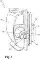
- Fig. 1 shows a perspective view of a central locking unit 50 of a tank or loading recess.
- Central locking unit 50 shown is designed as part of a tank or loading recess.
- the central locking unit 50 is preferably located on a section of the tank or loading recess which is opposite the section via which a lever arm with a tank cap is pivotably mounted.
- the lever arm is tensioned by a spring device and is held in the closed state of the tank or loading recess by the central locking unit 50.
- the tank or charging recess has a filler pipe and / or a charging module with a charging socket, which are inserted into an opening in a recess body of the tank or charging recess.
- An energy storage device can be charged with electrical current via the charging socket. Liquid or gaseous fuel can be fed to a vehicle tank via a filler pipe.
- the tank equipment and the tank or loading recess with the central locking unit 50 are part of a vehicle with a corresponding drive.
- the drive includes, for example, an internal combustion engine or an electric motor.
- so-called hybrid drives can also be provided, which have an internal combustion engine and an electric motor.
- Hybrid drives include serial or parallel hybrid drives.
- the central locking unit 50 has a housing 54.
- a spring and a guide element are received in the housing 54, by means of which the locking pin 12 is end and locked. Releasing the locking pin 12 can be done electrically, for example, a connection 52 being provided for this purpose.
- the central locking unit 50 is located on a wall section of the recess body.
- central locking unit 50 The design of a central locking unit 50 is known in various designs from the prior art.
- An essential feature of a central locking unit 50 is the locking of a lever arm or tank lid when the tank or loading recess is closed and the release of the lever arm or the tank lid by rotating the locking pin 12, which has a locking section 14 at its front end.
- the locking pin 12 is part of a locking device 10, which in turn is part of the central locking unit 50.
- the locking device 10 has a pressure piece 20.
- the pressure piece 20 is arranged in the locking section 14 and has a ball 26.
- the ball 26 is pressed out of a second receptacle 22 via a spring 24, the ball 26 being secured against falling out via an opening 28.
- the pressure piece 20 serves as a tolerance compensation element, so that when the tank or loading recess is closed there is no rattling of a lever arm or a tank flap.
- Conventional systems from the prior art have a resilient end piece on a locking pin, which consists of a soft component, to compensate for tolerances. The rotational and translational movement of the locking pin results in abrasion of the soft component. In this way, the tolerance compensation is no longer guaranteed and the tank flap or the lever arm rattles.
- the locking device 10 described here is essentially not subject to any wear and tear and therefore provides tolerance compensation even if it is operated frequently, which prevents a tank flap or a lever arm from rattling, for example.
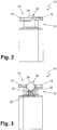
- FIG. 11 shows a schematic representation of a locking device 10 of the central locking unit 50 from FIG Fig. 1 .
- the locking pin 12 with a pressure piece 20 received therein is shown in a side view.
- the locking pin 12 has two projecting wings 18 in the locking section 14. When the locking pin 12 is displaced, the wings 18 are moved together with the locking pin 12 along its longitudinal axis and also rotated about the longitudinal axis. This releases or locks the lever arm of a tank flap.
- FIG. 11 shows a schematic sectional view of the locking device 10 from FIG Fig. 2 .
- the unlocked state is also shown.
- the ball 26 is pressed into the second receptacle 22 against the force of a spring 24 via the lever arm of a tank flap. Since the spring 24 endeavors as a compression spring, the ball 26 is back in the Figs. 2 and 3 To push back the starting position shown, play of the lever arm, which is in contact with the ball 26, is prevented. The lever arm can therefore not rattle.
- the lever arm of the fuel filler flap is over the Wing 28 held securely.
- a slight play despite the locking via the wings 18 is compensated for via the pressure piece 20 in the manner described above.
- the pressure piece 20 thus serves as a tolerance compensation and prevents rattling noises, for example, from occurring while driving.
- FIG. 11 shows a schematic sectional view of a pressure piece 20 of the locking device 10 from FIG Fig. 2 .
- the pressure piece 20 has a housing 36 which is inserted into a first receptacle 16 in the locking section 14.
- the housing 36 of the pressure piece 20 can be held securely in the first receptacle 16 by means of a press fit.
- the pressure piece 20 can have an adhesive ring on the outer circumferential surface of the housing 36, which additionally holds the housing 36 securely within the first receptacle and prevents it from slipping out.
- the housing 36 has a thread in sections on its outer circumference which, with a corresponding thread of the first receptacle 16, enables the pressure piece 20 to be screwed into the first receptacle 16.
- the spring 24 is supported against the floor 30 in the second receptacle 22.
- the opposite end of the spring 24 is supported on the ball 26.
- the ball 26 has a larger diameter 34 than the diameter 32 of the opening 28 in a ring 38 of the pressure piece 20.
- the ball 26 can therefore as in Fig. 4 shown protrude from the opening 28.
- Fig. 4 shows an unlocked state.
- the ball 26 In the locked state, the ball 26 is pressed into the receptacle 22 via the lever arm.
- the formation of the pressure piece 20 with a ball 26 allows in particular that the ball 26 can be rotated due to the translational and rotational movement of the locking pin 12 without abrasion occurring.
- the ball 26 consists of a metal, in particular stainless steel or a stainless steel alloy.
- the ball 26 can also consist of a ceramic.
- the ring 38 which in further embodiments can be designed as an adjusting ring with an internal thread.
- the housing 36 has a corresponding thread in the upper area.
- the setting ring 38 it is possible to change the distance between the ball 26 and the bottom 30 of the housing 36. A changed preload of the ball 26 can be achieved in this way. It is also possible to adapt the pressure piece 20 to different tolerances in a tank or loading recess.
- the formation of the ring 38 as an adjusting ring allows the ring 38 to be removed in further embodiments, so that both the ball 26 and the spring 30 can be exchanged or the second receptacle 22 can be cleaned.
- a ball 26 made of ceramic or a metal is not subject to such wear and even allows rotation. This provides a tolerance compensation that is designed to be durable and is essentially not subject to wear. Besides, it comes Even at high temperatures, soft components do not fuse, as can occur, for example, in the prior art. Furthermore, a ball 26 made of a ceramic or a metal is resistant to fuels and fuel vapors. The ball 26 cannot therefore be decomposed by fuels or vapors.
- the central locking unit 50 can have an emergency release which enables the locking pin 12 to be rotated via a cable. This ensures that it is unlocked if, for example, the electrical components fail.
Landscapes
- Engineering & Computer Science (AREA)
- Mechanical Engineering (AREA)
- Life Sciences & Earth Sciences (AREA)
- Sustainable Development (AREA)
- Sustainable Energy (AREA)
- Chemical & Material Sciences (AREA)
- Combustion & Propulsion (AREA)
- Transportation (AREA)
- Cooling, Air Intake And Gas Exhaust, And Fuel Tank Arrangements In Propulsion Units (AREA)
- Electric Propulsion And Braking For Vehicles (AREA)
- Quick-Acting Or Multi-Walled Pipe Joints (AREA)
Claims (9)
- Dispositif de verrouillage pour des berceaux de réservoir ou de chargement, avec une tige de verrouillage (12) qui présente à une extrémité une section de verrouillage (14) et peut être déplacée en translation et en rotation pour le verrouillage, dans lequel la tige de verrouillage (12) présente une pièce de pression (20) au niveau de la section de verrouillage (14), dans lequel la pièce de pression (20) présente un deuxième logement (22) dans laquelle un ressort (24) et une bille (26) ou une tige de pression sont agencés et la bille (26) ou la tige de pression sont poussées via le ressort (24) contre une ouverture (28) du deuxième logement (22) de la pièce de pression (20).
- Dispositif de verrouillage selon la revendication 1, dans lequel la tige de verrouillage (12) présente au niveau de la section de verrouillage (14) un premier logement (16) dans lequel la pièce de pression (20) est logée.
- Dispositif de verrouillage selon la revendication 1 ou 2, dans lequel la pièce de pression (20) est conçue en forme de cylindre et présente une bague de réglage ou une douille de réglage qui présentent l'ouverture (28) et peuvent être déplacées pour le réglage de la distance entre l'ouverture (28) et un fond (30) opposé.
- Dispositif de verrouillage selon l'une des revendications 1 à 3, dans lequel le diamètre (32) de l'ouverture (28) est inférieur au diamètre (34) de la bille (26) ou de la tige de pression.
- Dispositif de verrouillage selon l'une des revendications 1 à 4, dans lequel la pièce de pression (20) fait partie intégrante de la tige de verrouillage (12) ou est logée de façon interchangeable dans le premier logement (16).
- Dispositif de verrouillage selon l'une des revendications 1 à 5, dans lequel la tige de verrouillage (12) présente une rainure de guidage dans laquelle s'engage un élément de guidage.
- Dispositif de verrouillage selon la revendication 6, dans lequel la tige de verrouillage (12) est montée contre la force d'un second ressort dans un troisième logement.
- Dispositif de verrouillage selon l'une des revendications 1 à 7, dans lequel la bille (26) ou la tige de pression sont en acier inoxydable, en un alliage d'acier inoxydable ou en céramique.
- Berceau de réservoir ou de chargement avec au moins un dispositif de verrouillage (10) selon l'une des revendications 1 à 8, un corps de berceau, un bras de levier et un tube de remplissage ou un module de chargement, dans lequel le tube de remplissage de réservoir ou le module de chargement sont insérés dans une ouverture du corps de berceau et le bras de levier est monté en pivotement, et dans lequel le dispositif de verrouillage (10) est agencé de telle sorte qu'à l'état fermé du berceau de réservoir ou de chargement la bille (26) ou la tige de pression de la pièce de pression (20) soient au moins partiellement poussées via le bras de levier jusque dans le deuxième logement (22) de la pièce de pression (20) contre la force du ressort (24).
Applications Claiming Priority (2)
| Application Number | Priority Date | Filing Date | Title |
|---|---|---|---|
| DE102017116230.5A DE102017116230A1 (de) | 2017-07-19 | 2017-07-19 | Verriegelungseinrichtung für Tank- oder Lademulden und Tank- oder Lademulde |
| PCT/EP2018/068791 WO2019016044A1 (fr) | 2017-07-19 | 2018-07-11 | Dispositif de verrouillage pour goulottes de réservoir ou de chargement et goulotte de réservoir ou de chargement |
Publications (2)
| Publication Number | Publication Date |
|---|---|
| EP3655603A1 EP3655603A1 (fr) | 2020-05-27 |
| EP3655603B1 true EP3655603B1 (fr) | 2021-08-18 |
Family
ID=63113470
Family Applications (1)
| Application Number | Title | Priority Date | Filing Date |
|---|---|---|---|
| EP18750336.2A Active EP3655603B1 (fr) | 2017-07-19 | 2018-07-11 | Serrure pour entrée de carburant ou socle de chargement et entrée de carburant ou socle de chargement |
Country Status (5)
| Country | Link |
|---|---|
| US (1) | US20200207203A1 (fr) |
| EP (1) | EP3655603B1 (fr) |
| CN (1) | CN110998048B (fr) |
| DE (1) | DE102017116230A1 (fr) |
| WO (1) | WO2019016044A1 (fr) |
Families Citing this family (2)
| Publication number | Priority date | Publication date | Assignee | Title |
|---|---|---|---|---|
| DE102018125209A1 (de) * | 2018-10-11 | 2020-04-16 | Bayerische Motoren Werke Aktiengesellschaft | Tank- oder Ladeklappenanordnung |
| DE102022111137B4 (de) | 2021-05-21 | 2025-01-30 | Illinois Tool Works Inc. | Betätigungsvorrichtung zum öffnen und schliessen einer abdeckung in oder an einem fahrzeug |
Family Cites Families (9)
| Publication number | Priority date | Publication date | Assignee | Title |
|---|---|---|---|---|
| US2439057A (en) * | 1947-01-21 | 1948-04-06 | Weiser Company | Door or drawer latch |
| DE10148199A1 (de) * | 2001-09-21 | 2003-04-10 | Volkswagen Ag | Betätigungsvorrichtung für eine Abdeckung einer Karosserieöffnung |
| CN2755290Y (zh) * | 2004-12-10 | 2006-02-01 | 周曼桦 | 摩托车发动机用气门间隙自动调整器 |
| ITMC20060150A1 (it) * | 2006-11-13 | 2008-05-14 | So Ge Mi Spa | Dispositivo di apertura e di chiusura per sportelli. |
| DE102007024564A1 (de) * | 2007-05-25 | 2008-11-27 | Kiekert Ag | Kraftfahrzeugschließsystem mit Gleitelement |
| CN101363514A (zh) * | 2008-09-25 | 2009-02-11 | 上海汽车变速器有限公司 | 钢球弹簧滑块式同步器 |
| DE102009008496A1 (de) * | 2009-02-11 | 2010-08-12 | Illinois Tool Works Inc., Glenview | Arretiervorrichtung zur Arretierung einer Betätigungsvorrichtung mit Push-Push-Kinematik |
| JP6309276B2 (ja) * | 2014-01-10 | 2018-04-11 | 株式会社ニフコ | ラッチ装置 |
| CN205908326U (zh) * | 2016-08-17 | 2017-01-25 | 绵阳华博精工机械有限公司 | 一种低摩擦寿命长的汽车发动机用液压挺杆 |
-
2017
- 2017-07-19 DE DE102017116230.5A patent/DE102017116230A1/de not_active Withdrawn
-
2018
- 2018-07-11 US US16/631,263 patent/US20200207203A1/en not_active Abandoned
- 2018-07-11 EP EP18750336.2A patent/EP3655603B1/fr active Active
- 2018-07-11 WO PCT/EP2018/068791 patent/WO2019016044A1/fr not_active Ceased
- 2018-07-11 CN CN201880047721.4A patent/CN110998048B/zh active Active
Also Published As
| Publication number | Publication date |
|---|---|
| EP3655603A1 (fr) | 2020-05-27 |
| CN110998048B (zh) | 2021-10-15 |
| WO2019016044A1 (fr) | 2019-01-24 |
| US20200207203A1 (en) | 2020-07-02 |
| CN110998048A (zh) | 2020-04-10 |
| DE102017116230A1 (de) | 2019-01-24 |
Similar Documents
| Publication | Publication Date | Title |
|---|---|---|
| EP1805427B1 (fr) | Barre de traction-compression | |
| DE102009060119B4 (de) | Betätigungsvorrichtung | |
| EP3046800B1 (fr) | Dispositif de verrouillage électromécanique | |
| EP2704919B1 (fr) | Dispositif de verrouillage et siège de véhicule | |
| DE102014201886A1 (de) | Verschlussvorrichtung für eine Befüllungs- oder Anschlussöffnung an einem Fahrzeug | |
| DE202014106158U1 (de) | Schließhilfsantrieb für ein Kraftfahrzeugschloss | |
| DE10392415T5 (de) | Elektrische Lenkradschlossvorrichtung | |
| WO2011060963A1 (fr) | Coffret de rangement | |
| DE202011005545U1 (de) | Lenkrad für ein Kraftfahrzeug | |
| EP2705202A1 (fr) | Dispositif de verrouillage et siège de véhicule | |
| EP1473423A2 (fr) | Poignée de porte extérieure, notamment pour véhicules | |
| DE102007011541A1 (de) | Betätigungsvorrichtung für eine Abdeckung einer Karosserieöffnung eines Kraftfahrzeugs | |
| DE102011013255B4 (de) | Entriegelungsvorrichtung | |
| DE102017107839A1 (de) | Reibschlussanordnung für einen Antrieb eines Verschlusselements eines Kraftfahrzeugs | |
| DE102022102787A1 (de) | Öffnungs- und Schließvorrichtung für ein Kraftfahrzeug | |
| DE102012012852B4 (de) | Beschlag für einen Fahrzeugsitz sowie Fahrzeugsitz | |
| DE102015005646B4 (de) | Verriegelungseinrichtung für ein Kraftfahrzeug | |
| DE102022105329A1 (de) | Aufstellvorrichtung für eine Kraftfahrzeug-Tür | |
| DE102010063058A1 (de) | Verbindungsvorrichtung für einen Heckklappenantrieb eines Fahrzeugs | |
| DE102017116230A1 (de) | Verriegelungseinrichtung für Tank- oder Lademulden und Tank- oder Lademulde | |
| DE102019115979B4 (de) | Staufach | |
| DE202011000738U1 (de) | Verriegelungseinrichtung | |
| DE102021104132B4 (de) | Betätigungsvorrichtung für eine an einem bauteil beweglich gelagerte klappe sowie ein bauteil mit einer solchen betätigungsvorrichtung | |
| DE102022119787A1 (de) | Deckelvorrichtung und Kraftfahrzeug mit einer solchen Deckelvorrichtung | |
| DE102011121605A1 (de) | Anordnung zur Befestigung eines Betätigungshebels, Fahrzeug mit einer derartigen Befestigungsanordnung und Verfahren zur Befestigung eines Betätigungshebels |
Legal Events
| Date | Code | Title | Description |
|---|---|---|---|
| STAA | Information on the status of an ep patent application or granted ep patent |
Free format text: STATUS: UNKNOWN |
|
| STAA | Information on the status of an ep patent application or granted ep patent |
Free format text: STATUS: THE INTERNATIONAL PUBLICATION HAS BEEN MADE |
|
| PUAI | Public reference made under article 153(3) epc to a published international application that has entered the european phase |
Free format text: ORIGINAL CODE: 0009012 |
|
| STAA | Information on the status of an ep patent application or granted ep patent |
Free format text: STATUS: REQUEST FOR EXAMINATION WAS MADE |
|
| 17P | Request for examination filed |
Effective date: 20191212 |
|
| AK | Designated contracting states |
Kind code of ref document: A1 Designated state(s): AL AT BE BG CH CY CZ DE DK EE ES FI FR GB GR HR HU IE IS IT LI LT LU LV MC MK MT NL NO PL PT RO RS SE SI SK SM TR |
|
| AX | Request for extension of the european patent |
Extension state: BA ME |
|
| DAV | Request for validation of the european patent (deleted) | ||
| DAX | Request for extension of the european patent (deleted) | ||
| RIC1 | Information provided on ipc code assigned before grant |
Ipc: E05B 17/00 20060101ALI20210223BHEP Ipc: E05B 83/34 20140101ALI20210223BHEP Ipc: E05C 5/02 20060101ALI20210223BHEP Ipc: B60K 15/05 20060101ALI20210223BHEP Ipc: E05B 77/36 20140101AFI20210223BHEP Ipc: E05B 15/10 20060101ALI20210223BHEP |
|
| GRAP | Despatch of communication of intention to grant a patent |
Free format text: ORIGINAL CODE: EPIDOSNIGR1 |
|
| STAA | Information on the status of an ep patent application or granted ep patent |
Free format text: STATUS: GRANT OF PATENT IS INTENDED |
|
| INTG | Intention to grant announced |
Effective date: 20210406 |
|
| RIN1 | Information on inventor provided before grant (corrected) |
Inventor name: WERNER, STEPHAN |
|
| GRAS | Grant fee paid |
Free format text: ORIGINAL CODE: EPIDOSNIGR3 |
|
| GRAA | (expected) grant |
Free format text: ORIGINAL CODE: 0009210 |
|
| STAA | Information on the status of an ep patent application or granted ep patent |
Free format text: STATUS: THE PATENT HAS BEEN GRANTED |
|
| AK | Designated contracting states |
Kind code of ref document: B1 Designated state(s): AL AT BE BG CH CY CZ DE DK EE ES FI FR GB GR HR HU IE IS IT LI LT LU LV MC MK MT NL NO PL PT RO RS SE SI SK SM TR |
|
| REG | Reference to a national code |
Ref country code: GB Ref legal event code: FG4D Free format text: NOT ENGLISH |
|
| REG | Reference to a national code |
Ref country code: CH Ref legal event code: EP |
|
| REG | Reference to a national code |
Ref country code: DE Ref legal event code: R096 Ref document number: 502018006662 Country of ref document: DE |
|
| REG | Reference to a national code |
Ref country code: IE Ref legal event code: FG4D Free format text: LANGUAGE OF EP DOCUMENT: GERMAN Ref country code: AT Ref legal event code: REF Ref document number: 1421788 Country of ref document: AT Kind code of ref document: T Effective date: 20210915 |
|
| REG | Reference to a national code |
Ref country code: LT Ref legal event code: MG9D |
|
| REG | Reference to a national code |
Ref country code: NL Ref legal event code: MP Effective date: 20210818 |
|
| PG25 | Lapsed in a contracting state [announced via postgrant information from national office to epo] |
Ref country code: PT Free format text: LAPSE BECAUSE OF FAILURE TO SUBMIT A TRANSLATION OF THE DESCRIPTION OR TO PAY THE FEE WITHIN THE PRESCRIBED TIME-LIMIT Effective date: 20211220 Ref country code: NO Free format text: LAPSE BECAUSE OF FAILURE TO SUBMIT A TRANSLATION OF THE DESCRIPTION OR TO PAY THE FEE WITHIN THE PRESCRIBED TIME-LIMIT Effective date: 20211118 Ref country code: LT Free format text: LAPSE BECAUSE OF FAILURE TO SUBMIT A TRANSLATION OF THE DESCRIPTION OR TO PAY THE FEE WITHIN THE PRESCRIBED TIME-LIMIT Effective date: 20210818 Ref country code: BG Free format text: LAPSE BECAUSE OF FAILURE TO SUBMIT A TRANSLATION OF THE DESCRIPTION OR TO PAY THE FEE WITHIN THE PRESCRIBED TIME-LIMIT Effective date: 20211118 Ref country code: HR Free format text: LAPSE BECAUSE OF FAILURE TO SUBMIT A TRANSLATION OF THE DESCRIPTION OR TO PAY THE FEE WITHIN THE PRESCRIBED TIME-LIMIT Effective date: 20210818 Ref country code: FI Free format text: LAPSE BECAUSE OF FAILURE TO SUBMIT A TRANSLATION OF THE DESCRIPTION OR TO PAY THE FEE WITHIN THE PRESCRIBED TIME-LIMIT Effective date: 20210818 Ref country code: ES Free format text: LAPSE BECAUSE OF FAILURE TO SUBMIT A TRANSLATION OF THE DESCRIPTION OR TO PAY THE FEE WITHIN THE PRESCRIBED TIME-LIMIT Effective date: 20210818 Ref country code: RS Free format text: LAPSE BECAUSE OF FAILURE TO SUBMIT A TRANSLATION OF THE DESCRIPTION OR TO PAY THE FEE WITHIN THE PRESCRIBED TIME-LIMIT Effective date: 20210818 Ref country code: SE Free format text: LAPSE BECAUSE OF FAILURE TO SUBMIT A TRANSLATION OF THE DESCRIPTION OR TO PAY THE FEE WITHIN THE PRESCRIBED TIME-LIMIT Effective date: 20210818 |
|
| PG25 | Lapsed in a contracting state [announced via postgrant information from national office to epo] |
Ref country code: PL Free format text: LAPSE BECAUSE OF FAILURE TO SUBMIT A TRANSLATION OF THE DESCRIPTION OR TO PAY THE FEE WITHIN THE PRESCRIBED TIME-LIMIT Effective date: 20210818 Ref country code: LV Free format text: LAPSE BECAUSE OF FAILURE TO SUBMIT A TRANSLATION OF THE DESCRIPTION OR TO PAY THE FEE WITHIN THE PRESCRIBED TIME-LIMIT Effective date: 20210818 Ref country code: GR Free format text: LAPSE BECAUSE OF FAILURE TO SUBMIT A TRANSLATION OF THE DESCRIPTION OR TO PAY THE FEE WITHIN THE PRESCRIBED TIME-LIMIT Effective date: 20211119 |
|
| PG25 | Lapsed in a contracting state [announced via postgrant information from national office to epo] |
Ref country code: NL Free format text: LAPSE BECAUSE OF FAILURE TO SUBMIT A TRANSLATION OF THE DESCRIPTION OR TO PAY THE FEE WITHIN THE PRESCRIBED TIME-LIMIT Effective date: 20210818 |
|
| PG25 | Lapsed in a contracting state [announced via postgrant information from national office to epo] |
Ref country code: DK Free format text: LAPSE BECAUSE OF FAILURE TO SUBMIT A TRANSLATION OF THE DESCRIPTION OR TO PAY THE FEE WITHIN THE PRESCRIBED TIME-LIMIT Effective date: 20210818 |
|
| REG | Reference to a national code |
Ref country code: DE Ref legal event code: R097 Ref document number: 502018006662 Country of ref document: DE |
|
| PG25 | Lapsed in a contracting state [announced via postgrant information from national office to epo] |
Ref country code: SM Free format text: LAPSE BECAUSE OF FAILURE TO SUBMIT A TRANSLATION OF THE DESCRIPTION OR TO PAY THE FEE WITHIN THE PRESCRIBED TIME-LIMIT Effective date: 20210818 Ref country code: SK Free format text: LAPSE BECAUSE OF FAILURE TO SUBMIT A TRANSLATION OF THE DESCRIPTION OR TO PAY THE FEE WITHIN THE PRESCRIBED TIME-LIMIT Effective date: 20210818 Ref country code: RO Free format text: LAPSE BECAUSE OF FAILURE TO SUBMIT A TRANSLATION OF THE DESCRIPTION OR TO PAY THE FEE WITHIN THE PRESCRIBED TIME-LIMIT Effective date: 20210818 Ref country code: EE Free format text: LAPSE BECAUSE OF FAILURE TO SUBMIT A TRANSLATION OF THE DESCRIPTION OR TO PAY THE FEE WITHIN THE PRESCRIBED TIME-LIMIT Effective date: 20210818 Ref country code: CZ Free format text: LAPSE BECAUSE OF FAILURE TO SUBMIT A TRANSLATION OF THE DESCRIPTION OR TO PAY THE FEE WITHIN THE PRESCRIBED TIME-LIMIT Effective date: 20210818 Ref country code: AL Free format text: LAPSE BECAUSE OF FAILURE TO SUBMIT A TRANSLATION OF THE DESCRIPTION OR TO PAY THE FEE WITHIN THE PRESCRIBED TIME-LIMIT Effective date: 20210818 |
|
| PLBE | No opposition filed within time limit |
Free format text: ORIGINAL CODE: 0009261 |
|
| STAA | Information on the status of an ep patent application or granted ep patent |
Free format text: STATUS: NO OPPOSITION FILED WITHIN TIME LIMIT |
|
| 26N | No opposition filed |
Effective date: 20220519 |
|
| PG25 | Lapsed in a contracting state [announced via postgrant information from national office to epo] |
Ref country code: SI Free format text: LAPSE BECAUSE OF FAILURE TO SUBMIT A TRANSLATION OF THE DESCRIPTION OR TO PAY THE FEE WITHIN THE PRESCRIBED TIME-LIMIT Effective date: 20210818 |
|
| PG25 | Lapsed in a contracting state [announced via postgrant information from national office to epo] |
Ref country code: MC Free format text: LAPSE BECAUSE OF FAILURE TO SUBMIT A TRANSLATION OF THE DESCRIPTION OR TO PAY THE FEE WITHIN THE PRESCRIBED TIME-LIMIT Effective date: 20210818 |
|
| REG | Reference to a national code |
Ref country code: CH Ref legal event code: PL |
|
| GBPC | Gb: european patent ceased through non-payment of renewal fee |
Effective date: 20220711 |
|
| REG | Reference to a national code |
Ref country code: BE Ref legal event code: MM Effective date: 20220731 |
|
| PG25 | Lapsed in a contracting state [announced via postgrant information from national office to epo] |
Ref country code: LU Free format text: LAPSE BECAUSE OF NON-PAYMENT OF DUE FEES Effective date: 20220711 Ref country code: LI Free format text: LAPSE BECAUSE OF NON-PAYMENT OF DUE FEES Effective date: 20220731 Ref country code: CH Free format text: LAPSE BECAUSE OF NON-PAYMENT OF DUE FEES Effective date: 20220731 |
|
| PG25 | Lapsed in a contracting state [announced via postgrant information from national office to epo] |
Ref country code: GB Free format text: LAPSE BECAUSE OF NON-PAYMENT OF DUE FEES Effective date: 20220711 Ref country code: BE Free format text: LAPSE BECAUSE OF NON-PAYMENT OF DUE FEES Effective date: 20220731 |
|
| P01 | Opt-out of the competence of the unified patent court (upc) registered |
Effective date: 20230515 |
|
| PG25 | Lapsed in a contracting state [announced via postgrant information from national office to epo] |
Ref country code: IE Free format text: LAPSE BECAUSE OF NON-PAYMENT OF DUE FEES Effective date: 20220711 |
|
| PG25 | Lapsed in a contracting state [announced via postgrant information from national office to epo] |
Ref country code: MK Free format text: LAPSE BECAUSE OF FAILURE TO SUBMIT A TRANSLATION OF THE DESCRIPTION OR TO PAY THE FEE WITHIN THE PRESCRIBED TIME-LIMIT Effective date: 20210818 Ref country code: CY Free format text: LAPSE BECAUSE OF FAILURE TO SUBMIT A TRANSLATION OF THE DESCRIPTION OR TO PAY THE FEE WITHIN THE PRESCRIBED TIME-LIMIT Effective date: 20210818 |
|
| PG25 | Lapsed in a contracting state [announced via postgrant information from national office to epo] |
Ref country code: HU Free format text: LAPSE BECAUSE OF FAILURE TO SUBMIT A TRANSLATION OF THE DESCRIPTION OR TO PAY THE FEE WITHIN THE PRESCRIBED TIME-LIMIT; INVALID AB INITIO Effective date: 20180711 |
|
| REG | Reference to a national code |
Ref country code: AT Ref legal event code: MM01 Ref document number: 1421788 Country of ref document: AT Kind code of ref document: T Effective date: 20230711 |
|
| PG25 | Lapsed in a contracting state [announced via postgrant information from national office to epo] |
Ref country code: MT Free format text: LAPSE BECAUSE OF FAILURE TO SUBMIT A TRANSLATION OF THE DESCRIPTION OR TO PAY THE FEE WITHIN THE PRESCRIBED TIME-LIMIT Effective date: 20210818 |
|
| PG25 | Lapsed in a contracting state [announced via postgrant information from national office to epo] |
Ref country code: AT Free format text: LAPSE BECAUSE OF NON-PAYMENT OF DUE FEES Effective date: 20230711 |
|
| PG25 | Lapsed in a contracting state [announced via postgrant information from national office to epo] |
Ref country code: AT Free format text: LAPSE BECAUSE OF NON-PAYMENT OF DUE FEES Effective date: 20230711 |
|
| REG | Reference to a national code |
Ref country code: DE Ref document number: 502018006662 Ref country code: DE Ref legal event code: R082 Ref document number: 502018006662 Country of ref document: DE Representative=s name: ISARPATENT - PATENT- UND RECHTSANWAELTE PARTG , DE |
|
| REG | Reference to a national code |
Ref country code: DE Ref legal event code: R081 Ref document number: 502018006662 Country of ref document: DE Owner name: CEBI ITALY S.P. A. ANCONA, IT Free format text: FORMER OWNERS: CEBI ITALY S.P. A. ANCONA, OSIMO STAZIONE, IT; DR. SCHNEIDER KUNSTSTOFFWERKE GMBH, 96317 KRONACH, DE Ref country code: DE Ref legal event code: R081 Ref document number: 502018006662 Country of ref document: DE Owner name: MOTHERSON DRSC DEUTSCHLAND GMBH, DE Free format text: FORMER OWNERS: CEBI ITALY S.P. A. ANCONA, OSIMO STAZIONE, IT; DR. SCHNEIDER KUNSTSTOFFWERKE GMBH, 96317 KRONACH, DE Ref country code: DE Ref legal event code: R082 Ref document number: 502018006662 Country of ref document: DE Representative=s name: ISARPATENT - PATENT- UND RECHTSANWAELTE PARTG , DE |
|
| PGFP | Annual fee paid to national office [announced via postgrant information from national office to epo] |
Ref country code: DE Payment date: 20250722 Year of fee payment: 8 |
|
| PGFP | Annual fee paid to national office [announced via postgrant information from national office to epo] |
Ref country code: IT Payment date: 20250731 Year of fee payment: 8 |
|
| PGFP | Annual fee paid to national office [announced via postgrant information from national office to epo] |
Ref country code: FR Payment date: 20250723 Year of fee payment: 8 |
|
| PG25 | Lapsed in a contracting state [announced via postgrant information from national office to epo] |
Ref country code: TR Free format text: LAPSE BECAUSE OF FAILURE TO SUBMIT A TRANSLATION OF THE DESCRIPTION OR TO PAY THE FEE WITHIN THE PRESCRIBED TIME-LIMIT Effective date: 20210818 |
|
| PGFP | Annual fee paid to national office [announced via postgrant information from national office to epo] |
Ref country code: AT Payment date: 20260410 Year of fee payment: 5 |