EP3655609B1 - Dachfenstersystem mit verbesserten übergangsmitteln zwischen einem dachfenster und einer lüftungsanordnung - Google Patents
Dachfenstersystem mit verbesserten übergangsmitteln zwischen einem dachfenster und einer lüftungsanordnung Download PDFInfo
- Publication number
- EP3655609B1 EP3655609B1 EP18752415.2A EP18752415A EP3655609B1 EP 3655609 B1 EP3655609 B1 EP 3655609B1 EP 18752415 A EP18752415 A EP 18752415A EP 3655609 B1 EP3655609 B1 EP 3655609B1
- Authority
- EP
- European Patent Office
- Prior art keywords
- roof window
- ventilation
- window system
- rack
- frame
- Prior art date
- Legal status (The legal status is an assumption and is not a legal conclusion. Google has not performed a legal analysis and makes no representation as to the accuracy of the status listed.)
- Active
Links
Images


Classifications
-
- E—FIXED CONSTRUCTIONS
- E04—BUILDING
- E04D—ROOF COVERINGS; SKY-LIGHTS; GUTTERS; ROOF-WORKING TOOLS
- E04D13/00—Special arrangements or devices in connection with roof coverings; Protection against birds; Roof drainage ; Sky-lights
- E04D13/03—Sky-lights; Domes; Ventilating sky-lights
- E04D13/0325—Sky-lights; Domes; Ventilating sky-lights provided with ventilating means
-
- E—FIXED CONSTRUCTIONS
- E06—DOORS, WINDOWS, SHUTTERS, OR ROLLER BLINDS IN GENERAL; LADDERS
- E06B—FIXED OR MOVABLE CLOSURES FOR OPENINGS IN BUILDINGS, VEHICLES, FENCES OR LIKE ENCLOSURES IN GENERAL, e.g. DOORS, WINDOWS, BLINDS, GATES
- E06B7/00—Special arrangements or measures in connection with doors or windows
- E06B7/02—Special arrangements or measures in connection with doors or windows for providing ventilation, e.g. through double windows; Arrangement of ventilation roses
-
- E—FIXED CONSTRUCTIONS
- E04—BUILDING
- E04D—ROOF COVERINGS; SKY-LIGHTS; GUTTERS; ROOF-WORKING TOOLS
- E04D13/00—Special arrangements or devices in connection with roof coverings; Protection against birds; Roof drainage ; Sky-lights
- E04D13/03—Sky-lights; Domes; Ventilating sky-lights
-
- E—FIXED CONSTRUCTIONS
- E04—BUILDING
- E04D—ROOF COVERINGS; SKY-LIGHTS; GUTTERS; ROOF-WORKING TOOLS
- E04D13/00—Special arrangements or devices in connection with roof coverings; Protection against birds; Roof drainage ; Sky-lights
- E04D13/03—Sky-lights; Domes; Ventilating sky-lights
- E04D13/0305—Supports or connecting means for sky-lights of flat or domed shape
- E04D13/031—Supports or connecting means for sky-lights of flat or domed shape characterised by a frame for connection to an inclined roof
-
- E—FIXED CONSTRUCTIONS
- E04—BUILDING
- E04D—ROOF COVERINGS; SKY-LIGHTS; GUTTERS; ROOF-WORKING TOOLS
- E04D13/00—Special arrangements or devices in connection with roof coverings; Protection against birds; Roof drainage ; Sky-lights
- E04D13/03—Sky-lights; Domes; Ventilating sky-lights
- E04D13/035—Sky-lights; Domes; Ventilating sky-lights characterised by having movable parts
- E04D13/0351—Sky-lights; Domes; Ventilating sky-lights characterised by having movable parts the parts pivoting about a fixed axis
- E04D13/0354—Sky-lights; Domes; Ventilating sky-lights characterised by having movable parts the parts pivoting about a fixed axis the parts being flat
-
- F—MECHANICAL ENGINEERING; LIGHTING; HEATING; WEAPONS; BLASTING
- F24—HEATING; RANGES; VENTILATING
- F24F—AIR-CONDITIONING; AIR-HUMIDIFICATION; VENTILATION; USE OF AIR CURRENTS FOR SCREENING
- F24F13/00—Details common to, or for air-conditioning, air-humidification, ventilation or use of air currents for screening
- F24F13/08—Air-flow control members, e.g. louvres, grilles, flaps or guide plates
- F24F13/18—Air-flow control members, e.g. louvres, grilles, flaps or guide plates specially adapted for insertion in flat panels, e.g. in door or window-pane
-
- E—FIXED CONSTRUCTIONS
- E05—LOCKS; KEYS; WINDOW OR DOOR FITTINGS; SAFES
- E05Y—INDEXING SCHEME ASSOCIATED WITH SUBCLASSES E05D AND E05F, RELATING TO CONSTRUCTION ELEMENTS, ELECTRIC CONTROL, POWER SUPPLY, POWER SIGNAL OR TRANSMISSION, USER INTERFACES, MOUNTING OR COUPLING, DETAILS, ACCESSORIES, AUXILIARY OPERATIONS NOT OTHERWISE PROVIDED FOR, APPLICATION THEREOF
- E05Y2900/00—Application of doors, windows, wings or fittings thereof
- E05Y2900/10—Application of doors, windows, wings or fittings thereof for buildings or parts thereof
- E05Y2900/13—Type of wing
- E05Y2900/148—Windows
- E05Y2900/152—Roof windows
-
- E—FIXED CONSTRUCTIONS
- E06—DOORS, WINDOWS, SHUTTERS, OR ROLLER BLINDS IN GENERAL; LADDERS
- E06B—FIXED OR MOVABLE CLOSURES FOR OPENINGS IN BUILDINGS, VEHICLES, FENCES OR LIKE ENCLOSURES IN GENERAL, e.g. DOORS, WINDOWS, BLINDS, GATES
- E06B7/00—Special arrangements or measures in connection with doors or windows
- E06B7/02—Special arrangements or measures in connection with doors or windows for providing ventilation, e.g. through double windows; Arrangement of ventilation roses
- E06B7/10—Special arrangements or measures in connection with doors or windows for providing ventilation, e.g. through double windows; Arrangement of ventilation roses by special construction of the frame members
-
- F—MECHANICAL ENGINEERING; LIGHTING; HEATING; WEAPONS; BLASTING
- F24—HEATING; RANGES; VENTILATING
- F24F—AIR-CONDITIONING; AIR-HUMIDIFICATION; VENTILATION; USE OF AIR CURRENTS FOR SCREENING
- F24F13/00—Details common to, or for air-conditioning, air-humidification, ventilation or use of air currents for screening
- F24F13/28—Arrangement or mounting of filters
-
- F—MECHANICAL ENGINEERING; LIGHTING; HEATING; WEAPONS; BLASTING
- F24—HEATING; RANGES; VENTILATING
- F24F—AIR-CONDITIONING; AIR-HUMIDIFICATION; VENTILATION; USE OF AIR CURRENTS FOR SCREENING
- F24F2221/00—Details or features not otherwise provided for
- F24F2221/20—Details or features not otherwise provided for mounted in or close to a window
-
- F—MECHANICAL ENGINEERING; LIGHTING; HEATING; WEAPONS; BLASTING
- F24—HEATING; RANGES; VENTILATING
- F24F—AIR-CONDITIONING; AIR-HUMIDIFICATION; VENTILATION; USE OF AIR CURRENTS FOR SCREENING
- F24F7/00—Ventilation
- F24F7/007—Ventilation with forced flow
- F24F7/013—Ventilation with forced flow using wall or window fans, displacing air through the wall or window
Definitions
- the present invention relates to a roof window system
- a roof window system comprising a roof window having a frame including a frame top member, two side members and a bottom member, defining a frame plane, and a sash including a sash top member, sash side members and a bottom member, and a pane
- the roof window further comprising a ventilation device adapted for providing ventilation of a building in which the roof window is mounted, a ventilation assembly including a housing accommodating at least one ventilation unit connected to an aperture for air intake and exhaust, transition means being provided between the ventilation assembly and the frame top member and the sash top member of the roof window to accommodate a set of flow paths for air to and from the ventilation assembly.
- One area of focus is the windows of the building, since one of the primary functions in a window, besides admitting light, is to allow stale, warm, or otherwise used or spent air inside the building (so-called "room air”) to exit and allowing fresh air from the exterior (“outdoor air”) to enter the building in which the window is installed. This presupposes that the window is openable. Over time, the provision of ventilation in windows, also in situations in which the window is not open, either because it is a fixed window, or simply is not open, has become more or less standard equipment. This is the result of, among other things, increased focus on improving indoor climatic conditions and the microclimate in buildings.
- a roof window providing a ventilating aperture is the well-known VELUX® with a ventilation flap, which in pivot-hung windows also fulfils the double function of operating the window.
- Natural ventilation provided by such a ventilation device has a number of advantages. Among others, it is free of charge and noise-less. However, in certain fields of applications, for instance mechanical ventilation may be desirable. Examples of prior art roof window systems, including roof windows and ventilation assemblies, are shown in for instance Applicant's European patents EP0458725B1 and EP0372597B1 , and in published Danish patent application DK200001472A . Other examples are shown in documents DE102004037563A1 , 20204020630U1 , DE19811469A1 and DE2906729U1 .
- roof windows and ventilation assemblies provide well-functioning solutions, they also require that the roof window is built to receive such a ventilation assembly, typically by designing special parts and/or requiring further investment in the installation of auxiliary parts and installation equipment. Thus, severe limitations as to retro-fitting existing windows exist.
- the ventilation assembly takes in outdoor air via ventilation units having flow channels connected to the ventilation device of the roof window and, conversely, allows room air to be led to the exterior in the form of exhaust air through the ventilation assembly.
- the ventilation units comprise a ventilator and a heat exchange device in the form of a regenerator.
- the counterpart commercial product has proven to work well, and the roof window system alleviates the disadvantages of the earlier prior art to a great extent.
- One document devising further improvements of the above EP application is found in DE utility model 20 2016 100 906 U1 .
- said transition means comprise between said at least one ventilation assembly and the top sash member a plurality of apertures extending through the frame top member
- a roof window system in which the transition between the two components of the roof window system, i.e. the roof window and the ventilation assembly, is carried out at a position which is as neutral as possible, that is, rather than leading the flow paths above the top frame member as in the prior art, the frame may accommodate other equipment as well, for instance a top hinge device. Furthermore, guiding the air through the frame top member also entails improved insulation properties, as the flow paths will extend through an area with better insulation.
- the plurality of apertures extending through the frame top member are located mainly in the bottom half part of the height of the frame top member, more preferably in the lower third part of the height of the frame top member.
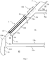
- the roof window system comprises a roof window 1 and a ventilation assembly generally designated 100.
- the roof window 1 comprises at least one frame, in the embodiment shown and described two frames, of which one frame 2 is a stationary frame and an openable sash 3 encasing a pane 4. Details of the frame 2 and sash 3 are shown in more detail in i.a. Figs 13, 14 and 19 .
- the frame 2 is, in a manner known per se, substantially rectangular and has a top member 21, and further a bottom member 22, and two side members, not shown in detail.
- the sash 3 has a top member 31 and two side members 32, 33, and further a bottom member, not shown in detail.
- the frame 2 is adapted to be built into a roof structure of virtually any kind, typically comprising a number of rafters and battens, and further non-shown details such as vapour barrier collars etc., below a roofing material constituting a roofing 71 as shown in Fig. 2 .
- FIG. 2 an embodiment of the roof window system is shown installed in an upstairs room 81 of a multi-storey building.
- an attic 82 is present above the room 81; however, this could also be a further inhabited storey, or a loft.
- a downstairs room 83 is present below the room 81.
- the downstairs storey is the first, or ground, floor of a house, the room 81 located upstairs being thus located on the second floor of the house.
- the frame 2 is built into the roof structure such that the frame plane is substantially parallel to roofing 71.
- the transition to the room 81 in the upstairs storey is here provided in that a set of lining panels comprising a top lining panel 73a, two side lining panels of which one side lining panel 73b is shown, and a bottom lining panel 73c, adjoins an inclined inner wall 72 of the upstairs room 81.
- the bottom lining panel 73c is here shown connected to a window sill 74 and further to a knee wall 75 closest to a floor 77b of the upstairs storey, i.e. typically the second floor of a house.
- a different bottom lining panel could extend directly from the frame 2 to the floor 77b.
- the upstairs room 81 has a ceiling 76a which in turn adjoins the storey partition to the attic 82, here shown with a floor 76b and an inner wall 79.
- the floor 77b of the upstairs room adjoins the storey partition to the downstairs storey and hence to downstairs room 83, having a ceiling 77a and an inner wall 78 which is typically vertical.
- roof void 84 is shown formed behind the knee wall 75.
- the roof void 84 typically unused space, but may be utilised for piping, wiring and additional insulation, and alternatively or additionally also for storage.
- the roof window 1 is centre-hung in that the sash 3 is connected to the frame 2 by a pivot hinge (not shown) provided between side members of the frame 2 and sash 3, respectively, to be openable by tilting the sash 3 of the window 1 about a pivot hinge axis defined by the pivot hinge.
- a closed position of the roof window 1 means a position in which the frame plane and the sash plane coincide, that is form an angle of 0 degrees with each other.
- an open position of the roof window 1 as used herein generally means a position in which the sash 3 is tilted about the pivot hinge axis such that the frame plane and the sash plane no longer coincide.
- the window according to the invention may in other embodiments be top-hung, with or without an intermediate frame structure, have the hinge axis somewhere between the top and the centre, be side-hung or for that matter even be bottom-hung, or fixed, i.e. not openable.
- the roof window system also provides for optional ventilation in the closed position of the window.
- the window may be electrically operated, or prepared for retrofitting of an electrical operator.
- the roof window system comprises a screening arrangement 5 in the form of a roller shutter, in the embodiment shown.
- the sash 3 and frame 2 of the window of the system according to the invention may be made of wooden members or members made of cast or extruded polyurethane (PUR).
- PUR cast or extruded polyurethane
- the frame 2 and sash 3 are protected, in a manner known per se, by an assembly of cover elements generally designated 6 and including a cladding and a flashing arrangement.
- cover elements generally designated 6 and including a cladding and a flashing arrangement.
- a suitable finishing may be provided, for instance comprising a lining panel.
- the interior side of the sash members are substantially flush with the interior side of the frame members.
- the frame bottom member 22 may be provided with an over-height, that is, taller than is necessary in order to surround the sash 3, which in turn makes it possible to utilise standard flashing members at the bottom, even if the roof window 1 is installed at a deep position in the roof structure.
- the roof window 1 of the system of the invention forms part of a roof window system, which in addition to the roof window 1 comprises a ventilation assembly generally designated 100.
- the ventilation assembly 100 is positioned above the top member of the window frame 2 as seen in the inclination of the roof.
- the roof window 1 is installed to provide light and ventilation in the room 81 located upstairs in the multi-storey building, namely a room adjacent or at least in proximity to the inclined roof.
- the ventilation assembly 100 at the frame top member 21 is in fluid connection with a ventilation device of the roof window 1, here generally designated 40.
- the ventilation device in the embodiment shown comprises a ventilation flap 40, which is connected to the top member 31 of the sash 3 via a hinge connection 41 and which furthermore comprises a handle 42.
- the handle 42 rotates the ventilation flap 40 from an open position to a closed position and vice versa.
- One or more intermediate positions, in which the ventilation flap 40 may be temporarily locked, may be defined between the open and closed position.
- the sash 3 is pivotally connected to the frame 2, and the ventilation flap 40 is adapted to assume three position, viz. a first or closed position, in which the roof window 1 is closed and no ventilation is provided, a second and ventilating position, in which the roof window 1 is still closed but a ventilation aperture is provided to allow air passage, and a third and entirely open position, in which the sash 3 is able to pivot relative to the frame 2 to open the window.
- the ventilation flap 40 may be able to assume only two position, viz. a closed position and an open, ventilating position, whereas operation of the sash takes place in other ways, for instance by a handle or other operating means located at the bottom member of the sash.
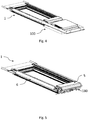
- Ventiler assembly 100 Details of one embodiment of the ventilation assembly 100 will now be described in further detail with reference to in particular Figs 6 to 10 .
- the reference includes also ventilation units with ventilators and regenerators accommodated in the ventilation assembly.
- the ventilation assembly 100 comprises a housing 150 and a cover 151.
- the cover 151 has two apertures 152 for air intake and exhaust, the apertures 152 being provided at mutually opposite sides of the cover 151.
- Transition means provided between the ventilation assembly 100 and the top frame member 21 and the sash top member 31 of the roof window 1 of the system according to the invention will now be described in some detail. As in the prior art, these transition means are configured to accommodate a set of flow paths to and from the ventilation assembly 100.
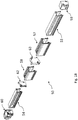
- the housing 150 of the ventilation assembly 100 is composed of three main components, namely in the form of a plurality of sections including a bottom section 161, an intermediate section 162 and a top section 163.
- Each of these sections is made of an insulating material.
- the material is preferably easy to manufacture and handle during assembly. It is also advantageous that the material is light-weight. In any event, the material should be able to withstand compressional and tensional forces to a certain extent and furthermore be able to provide the tightness required in such a ventilation assembly.
- EPP expanded polypropylene
- the top section 163 functions as a cover to the bottom section 161, and is configured to accommodate internal parts of the ventilation units, cf. Figs 7 and 8 .
- the bottom section 161 has a depth which exceeds that of the roof window 1, i.e. the bottom section 161 is located deep in the roof structure which is advantageous from an insulation point of view.
- the bottom section 161 is provided with a number of recesses or depressed portions, of which flow channel 1501 is shown in Fig. 9 to represent the set of flow channels present in the housing 150 of the ventilation assembly 100 to form a fluid connection with the flow paths through the transition means.
- the bottom section 161 has an entrance portion 161a, which together with the underside of the intermediate section 162 forms an opening constituting a transition channel 1601 to the roof window 1.
- entrance portion 161a there are three other entrance portions corresponding to entrance portion 161a, which in turn provides for four transition channels 1601, 1602, 1603, 1604. All of these transition channels thus form part of the transition means between the ventilation assembly 100 and the roof window 1 and are here formed integrally in the housing 150 of the ventilation assembly 100.
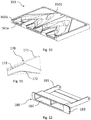
- the transition channels 1601, 1602, 1603, 1604 are in direct connection with apertures 2101, 2102, 2103, 2104 in the frame top member 21 (cf. Fig. 12 ).
- the bottom section 161 and the intermediate section 162 abut directly on the outer side of the frame top member 21 such that a substantially tight transition is achieved for the air flowing between the room in which the roof window is mounted and the ventilation assembly and vice versa.
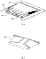
- the transition means comprise a filter assembly as follows:
- a filter rail 170 is accommodated in the entrance portion 161a in the bottom section 161 of the housing 150.
- the filter rail 170 is preferably releasably connected to the housing 150.
- the releasable connection is carried out in that a flange 171 on the filter rail 170 rests on shoulder portion 161b of bottom section 161.
- the filter rail 170 is provided with lower guide 172 and upper guide 173, which form a track to receive a filter holder 180 by a leg 181 thereof.
- the filter holder 182 has an opening 182 through which air flows and a surrounding flange 183 to abut on a ventilation rack 50 accommodated on the top sash member 31 as will be described in the following, and furthermore accommodates a filter element 184.
- the filter holder 180 and the remaining three filter holders, which may be identical to the filter holder 180, are received in the apertures 2101-2104 of the frame top member 21.
- the filter holder 180 located in the aperture 2101 is shown without a filter element, whereas the filter element 184 shown in aperture 2102 is shown without its filter holder.
- the provision of a filter assembly contributes to an improved interior climate in the building.
- the filter elements may easily be cleaned or exchanged on a regular basis in order to maintain the indoor climate at a high level.
- a central feature of the invention emanates from in particular Figs 13 and 14 , namely that the transition means between the roof window 1 and the ventilation assembly 100, in the embodiment shown represented by filter holder 180 accommodated in aperture 2101, are located in the bottom part of the frame top member 21.
- the apertures 2101, 2102, 2103, 2104 extending through the frame top member 21 are located mainly in the bottom half part of the height of the frame top member 21, more preferably in the lower third part of the height of the frame top member 21.
- the apertures in the frame top member are located below, in the height direction of the frame top member 21, internal equipment located at the top of the roof window, such internal equipment selected from the list comprising at least one of: a top hinge device, electrical operator means, a covering assembly, and a screening arrangement.
- internal equipment is generally designated 90 in Fig. 14 ; the screening arrangement 5 is shown in Fig. 5 but has been removed from the detailed view of Fig. 14 for ease of readability.
- the relative positioning of the internal equipment, which does not require insulation, on one hand, and the apertures through which air will be transferred, entails an improved overall energy performance of the roof window system.
- the ventilation rack generally designated 50 comprises a plurality of rack sections.
- rack sections are dedicated to ventilation, i.e. to provide a flow path for air to and from the ventilation assembly 100. This applies to a first rack section 51 with aperture 5101, second rack section 52 with aperture 5202, third rack section 53 with aperture 5303 and fourth rack section 54 with aperture 5404.
- said plurality of rack sections here comprise a fifth rack section 55 with an aperture 5505 configured to receive locking means (not shown) and a sixth rack section 56 with an aperture 5606 configured to accommodate operating means of an electrical operator.
- Seventh and eighth rack sections 57 and 58 correspond to sixth and fifth rack sections 56 and 55, respectively.
- the rack sections 51-58 are positioned symmetrically about a central rack section 59, but other configurations are conceivable.
- an end rack piece 60, 61 is provided at the ends of the ventilation rack 50.
- one half of the ventilation rack 50 of Figs 16 and 17 is shown, including two rack bridge pieces 62 and 63.
- the set of standardised rack sections may also include sections with blind or knock-out plates to be removed in order to accommodate equipment of such accessories.
- the ventilation rack 50, and in the embodiment shown, the rack sections may be manufactured in any suitable way and from any suitable material, for instance moulding of a plastic material.
- a frame gasket 211 (frame top member 21 removed in Fig. 14 , frame gasket 211 thus shown in a "loose" connection). Together with other sealing elements along the side and bottom of the roof window 1, this frame gasket 211 forms a first, or exterior, sealing plane.
- a sash gasket 311 correspondingly with other sealing elements, forms a second, or interior, sealing plane.
- the sash gasket 311 is received in a track 504 in the ventilation rack 50.
- the respective rack sections are provided with track portions (not shown in detail) to form the coherent, through track 504.
- a plurality of brush seals 501, 502, 503 are connected to the central rack section 59 and the end rack pieces 62, 63, respectively. Together with the frame gasket 211 and the sash gasket 311, the brush seals 501, 502, 503 form one or more closed chambers at the intersection between the frame 2 and the sash 3, here two closed chambers on either side of the central rack section 59.
- two flow channels between the roof window 1 and the ventilation assembly 100 pass in each of these closed chambers.
- the presence of such closed chambers are advantageous from a flow and insulation point of view, which in turn contributes to the improved environmental conditions.
- the roof window 1 is connected to the ventilation assembly 100 at the top member 21 of the window frame 2.
- the ventilation assembly 100 in the following referred to as first ventilation assembly 100, will provide ventilation to the upstairs room 81 as described.
- An additional, second ventilation assembly 200 is in this embodiment provided at the frame bottom member 22.
- the second ventilation assembly 200 is in fluid connection with the downstairs room 83 by means of a duct 201 and a second ventilation device, here in the form of ceiling ventilation device 202 mounted in the ceiling 77a of the downstairs room 83.
- the second ventilation assembly 200 and the duct 201 are accommodated in the roof void 84.
- the duct 201 is here shown as a vertical element extending directly to the ceiling ventilation device 202 in the downstairs room 83 immediately below the upstairs room 81, it is conceivable to provide additional ducting distributing air to and from other downstairs rooms, either on the same floor or in other storeys of the building.
- the second ventilation assembly 200 is preferably provided in fluid connection with the first ventilation assembly 100.
- the fluid connection is not shown in detail, but may for instance be provided in the form of ducts located along the side members of frame 2 as will be apparent to the person skilled in the art.
- the first ventilation assembly 100 provides for the air intake and exhaust, and possibly regeneration as described in the above, and the second ventilation assembly 200 may then be of a simpler design, providing only transfer of fresh air from the exterior to the downstairs room 83 and of stale air from the room 83 to the exterior via the first ventilation assembly.
- the second ventilation assembly 200 is connected directly to the exterior, and not necessarily to the first ventilation assembly 100.
- Intake of fresh air from the outdoors may for instance be provided in the form of apertures in the cladding and covering elements allowing entry and exit of air, but not precipitation, and the second ventilation assembly 200 is then preferably self-contained in that one or more ventilation units are provided within the second ventilation assembly 200 to enable mechanical ventilation.
- the second ventilation assembly 200 By connecting the second ventilation assembly 200 to the downstairs room 83, it is possible to utilise the aperture in the roof surface, which is traditionally only covered by the roof window 1, as a gateway to mechanical ventilation of rooms on the ground floor (or lower floors), in addition to the room that the roof window 1 is located in.
- the roof window system including a first ventilation assembly 100 and a second ventilation assembly may be used as a simple, decentralised system to transfer heat from a room or rooms on one storey of a building to another.
- a first ventilation assembly 100 and a second ventilation assembly may be used as a simple, decentralised system to transfer heat from a room or rooms on one storey of a building to another.
- heated air accumulating under the ceiling 77a of the downstairs room 83, resulting from a stove, fireplace or another heat source could be used for transferring the heated air via the second ventilation device 202 to the ventilation device 40 of the roof window 1, thereby heating the second floor room 81.
Landscapes
- Engineering & Computer Science (AREA)
- Civil Engineering (AREA)
- Structural Engineering (AREA)
- Architecture (AREA)
- Chemical & Material Sciences (AREA)
- Combustion & Propulsion (AREA)
- Mechanical Engineering (AREA)
- General Engineering & Computer Science (AREA)
- Building Environments (AREA)
- Specific Sealing Or Ventilating Devices For Doors And Windows (AREA)
Claims (19)
- Dachfenstersystem, umfassend:ein Dachfenster (1) mit einem Rahmen (2), der ein oberes Rahmenglied (21), zwei Seitenglieder und ein unteres Glied (22) aufweist, die eine Rahmenebene definieren, und einem Flügel (3), der ein oberes Flügelglied (31), Flügelseitenglieder (32) und ein unteres Glied aufweist, und einer Scheibe (4), wobei das Dachfenster (1) ferner mindestens eine Belüftungsvorrichtung (40) umfasst, die zur Bereitstellung von Belüftung eines Gebäudes, in dem das Dachfenster montiert ist, ausgeführt ist,mindestens eine Belüftungsanordnung (100, 200), die ein Gehäuse (150) aufweist, in dem mindestens eine Belüftungseinheit untergebracht ist, die mit einer Öffnung (152) für Zuluft und Abluft verbunden ist, Übergangsmittel, die zur Aufnahme eines Strömungswegsatzes für Luft zu und von der Belüftungsanordnung (100) zwischen der mindestens einen Belüftungsanordnung (100) und dem oberen Rahmenglied (21) und dem oberen Flügelglied (31) des Dachfensters (1) vorgesehen sind, dadurch gekennzeichnet, dassdie Übergangsmittel zwischen der mindestens einen Belüftungsanordnung (100) und dem oberen Flügelglied (31) eine Vielzahl von Öffnungen (2101, 2102, 2103, 2104) umfassen, die sich durch das obere Rahmenglied (21) erstrecken.
- Dachfenstersystem nach Anspruch 1, wobei die Vielzahl von Öffnungen (2101, 2102, 2103, 2104), die sich durch das obere Rahmenglied (21) erstrecken, hauptsächlich in der unteren Hälfte der Höhe des oberen Rahmenglieds (21), bevorzugter im unteren Drittel der Höhe des oberen Rahmenglieds (21), angeordnet sind.
- Dachfenstersystem nach Anspruch 1 oder 2, wobei das Dachfenstersystem eine innere Ausrüstung umfasst, die aus der Liste ausgewählt ist, die Folgendes umfasst: eine obere Scharniervorrichtung und/oder elektrische Betätigungsmittel und/oder eine Abdeckanordnung und/oder eine Abschirmungsanordnung.
- Dachfenstersystem nach einem der vorhergehenden Ansprüche, wobei die Übergangsmittel weitere Mittel umfassen, die integral in dem Gehäuse (150) der Belüftungsanordnung (100) ausgebildet sind.
- Dachfenstersystem nach Anspruch 4, wobei das Gehäuse einen unteren Abschnitt (161) und einen Zwischenabschnitt (162) umfasst und wobei die weiteren Mittel eine Vielzahl von Übergangskanälen (1601, 1602, 1603, 1604) umfassen, die als eine Öffnung zwischen einem ausgesparten Eingangsabschnitt (161a) des unteren Abschnitts (161) und der Unterseite des Zwischenabschnitts (162) ausgebildet sind.
- Dachfenstersystem nach Anspruch 5, wobei der untere Abschnitt (161) und der Zwischenabschnitt (162) des Gehäuses (150) aus einem Isoliermaterial wie expandiertem Polypropylen (EPP) hergestellt sind, wobei das Gehäuse (150) vorzugsweise auch einen oberen Abschnitt (163) aus demselben Material aufweist.
- Dachfenstersystem nach einem der vorhergehenden Ansprüche, wobei die Übergangsmittel eine Filteranordnung umfassen, die eine mit dem Gehäuse (150) der Belüftungsanordnung (100) verbundene Filterschiene (170) umfassen, die zur Aufnahme eines Filterhalters (180) ausgestaltet ist, der dazu ausgestaltet ist, in der Vielzahl von sich durch das obere Rahmenglied (21) erstreckenden Öffnungen (2101, 2102, 2103, 2104) aufgenommen zu werden.
- Dachfenstersystem nach Anspruch 7, wobei die Filterschiene (170) freigebbar mit dem Gehäuse (150) verbunden und mit Führungen (172, 173) versehen ist, die eine zur Aufnahme eines Schenkels (181) des Filterhalters (182) ausgestaltete Spur bilden.
- Dachfenstersystem nach einem der vorhergehenden Ansprüche, wobei die Übergangsmittel ein Belüftungsgestell (50) umfassen, das an dem oberen Flügelglied (31) untergebracht ist.
- Dachfenstersystem nach Anspruch 9, wobei das Belüftungsgestell (50) eine modulare Konfiguration hat, die einen Satz normierter Gestellabschnitte umfasst, der eine Vielzahl von Gestellabschnitten (51, 52, 53, 54), die für die Belüftung bestimmt sind, aufweist sowie eine jeweilige Öffnung (5101, 5202, 5303, 5404) aufweist, die zum Bilden einer Fluidverbindung mit den Öffnungen (2101, 2102, 2103, 2104) in dem oberen Rahmenglied (21) ausgestaltet ist.
- Dachfenstersystem nach Anspruch 10, wobei der Satz normierter Gestellabschnitte ein Gestellendteil (62, 63) und einen mittleren Gestellabschnitt (59) aufweist sowie vorzugsweise einen Gestellabschnitt (55) mit einer Öffnung (5505), die zur Aufnahme von Verriegelungsmitteln ausgestaltet ist, und/oder einen Gestellabschnitt (56) mit einer Öffnung (5606), die zur Unterbringung von Betätigungsmitteln einer elektrischen Betätigungsvorrichtung des Dachfenstersystems ausgestaltet ist.
- Dachfenstersystem nach einem der Ansprüche 9 bis 11, wobei das Dachfenster (1) eine Rahmendichtung (211), die eine erste Dichtungsebene definiert, und eine Flügeldichtung (311) umfasst, die eine zweite Dichtungsebene definiert, und wobei die Flügeldichtung (311) in einer Spur (504) in dem Belüftungsgestell (50) aufgenommen ist.
- Dachfenstersystem nach Anspruch 12, wobei eine Vielzahl von Bürstendichtungen (501, 502, 503) mit dem Belüftungsgestell (50) verbunden sind, um zusammen mit der Rahmendichtung (211) und der Flügeldichtung (311) eine oder mehrere geschlossene Kammern zu bilden, wobei die Strömungswege der Übergangsmittel zu der Vielzahl von sich durch das obere Rahmenglied (21) erstreckenden Öffnungen (2101, 2102, 2103, 2104) in der einen oder den mehreren geschlossenen Kammern angeordnet sind.
- Dachfenstersystem nach Ansprüchen 11 und 13, wobei eine erste Bürstendichtung (501) mit dem mittleren Gestellabschnitt (59) verbunden ist, eine zweite Bürstendichtung (502) mit einem Gestellendteil (62) verbunden ist und eine dritte Bürstendichtung (503) mit einem anderen Gestellendteil (63) verbunden ist.
- Dachfenstersystem nach Anspruch 14, wobei die Übergangsmittel vier sich durch das obere Rahmenglied (21) erstreckende Öffnungen (2101, 2102, 2103, 2104) umfassen und das Belüftungsgestell (50) vier für die Belüftung bestimmte Gestellabschnitte aufweist und wobei zwei der jeweiligen Öffnungen (5101, 5202; 5303, 5404) des ersten, zweiten, dritten und vierten Gestellabschnitts (51, 52, 53, 54) in jeder geschlossenen Kammer angeordnet sind, die durch die jeweiligen Bürstendichtungen (501, 502; 501, 503), die Rahmendichtung (211) und die Flügeldichtung (311) gebildet ist.
- Dachfenstersystem nach einem der vorhergehenden Ansprüche, wobei zusätzlich zu der ersten Belüftungsanordnung (100), die an dem oberen Rahmenglied (21) des Dachfensters (1) vorgesehen ist, eine zweite Belüftungsanordnung (200) an dem unteren Rahmenglied (22) vorgesehen ist.
- Dachfenstersystem nach Anspruch 16, wobei das Dachfenster (1) eingebaut ist, um einen Raum (81) zu belüften, der sich in einem oberen Stockwerk eines mehrgeschossigen Gebäudes befindet, wobei die an dem oberen Rahmenglied (21) vorgesehene erste Belüftungsanordnung (100) mit der Belüftungsvorrichtung (40) des Dachfensters (1) verbunden ist, um den Raum (81) im oberen Stockwerk zu belüften, und wobei die an dem unteren Rahmenglied (22) vorgesehene zweite Belüftungsanordnung (200) installiert ist, um in mindestens einem anderen Raum (83) für Belüftung zu sorgen, der sich bezüglich des Raums (81), in dem die ersten Belüftungsanordnung (100) für Belüftung sorgt, in einem unteren Stockwerk befindet.
- Dachfenstersystem nach Anspruch 17, wobei die zweite Belüftungsanordnung (200) mittels einer Leitung (201) und einer zweiten Belüftungsvorrichtung (202) in Fluidverbindung mit dem mindestens einen anderen Raum (83) steht.
- Dachfenstersystem nach einem der Ansprüche 16 bis 18, wobei die zweite Belüftungsanordnung (200) in Fluidverbindung mit der ersten Belüftungsanordnung (100) steht.
Priority Applications (2)
| Application Number | Priority Date | Filing Date | Title |
|---|---|---|---|
| EP21179116.5A EP3901404B1 (de) | 2017-07-21 | 2018-07-20 | Dachfenstersystem mit einer lüftungsanordnung und verfahren zur belüftung |
| PL18752415T PL3655609T3 (pl) | 2017-07-21 | 2018-07-20 | System okna dachowego z ulepszonymi środkami przejściowymi pomiędzy oknem dachowym a zespołem wentylacyjnym |
Applications Claiming Priority (2)
| Application Number | Priority Date | Filing Date | Title |
|---|---|---|---|
| DKPA201770587A DK180102B1 (en) | 2017-07-21 | 2017-07-21 | Roof window system with improved transition means between a roof window and a ventilation assembly |
| PCT/DK2018/050185 WO2019015732A1 (en) | 2017-07-21 | 2018-07-20 | ROOF WINDOW SYSTEM INCLUDING IMPROVED TRANSITION MEANS BETWEEN A ROOF WINDOW AND A VENTILATION ASSEMBLY |
Related Child Applications (2)
| Application Number | Title | Priority Date | Filing Date |
|---|---|---|---|
| EP21179116.5A Division EP3901404B1 (de) | 2017-07-21 | 2018-07-20 | Dachfenstersystem mit einer lüftungsanordnung und verfahren zur belüftung |
| EP21179116.5A Division-Into EP3901404B1 (de) | 2017-07-21 | 2018-07-20 | Dachfenstersystem mit einer lüftungsanordnung und verfahren zur belüftung |
Publications (2)
| Publication Number | Publication Date |
|---|---|
| EP3655609A1 EP3655609A1 (de) | 2020-05-27 |
| EP3655609B1 true EP3655609B1 (de) | 2021-08-25 |
Family
ID=63144784
Family Applications (2)
| Application Number | Title | Priority Date | Filing Date |
|---|---|---|---|
| EP18752415.2A Active EP3655609B1 (de) | 2017-07-21 | 2018-07-20 | Dachfenstersystem mit verbesserten übergangsmitteln zwischen einem dachfenster und einer lüftungsanordnung |
| EP21179116.5A Active EP3901404B1 (de) | 2017-07-21 | 2018-07-20 | Dachfenstersystem mit einer lüftungsanordnung und verfahren zur belüftung |
Family Applications After (1)
| Application Number | Title | Priority Date | Filing Date |
|---|---|---|---|
| EP21179116.5A Active EP3901404B1 (de) | 2017-07-21 | 2018-07-20 | Dachfenstersystem mit einer lüftungsanordnung und verfahren zur belüftung |
Country Status (8)
| Country | Link |
|---|---|
| US (1) | US11242686B2 (de) |
| EP (2) | EP3655609B1 (de) |
| CN (1) | CN110945204B (de) |
| DE (1) | DE202018006681U1 (de) |
| DK (1) | DK180102B1 (de) |
| ES (1) | ES2890953T3 (de) |
| PL (2) | PL3655609T3 (de) |
| WO (1) | WO2019015732A1 (de) |
Families Citing this family (5)
| Publication number | Priority date | Publication date | Assignee | Title |
|---|---|---|---|---|
| DK180879B1 (en) | 2019-12-30 | 2022-06-13 | Vkr Holding As | A roof window system with a ventilation unit mounted adjacent to the roof window, and a method of providing ventilation for a building |
| DK180977B1 (en) | 2019-12-30 | 2022-08-29 | Vkr Holding As | A roof window system with a ventilation unit mounted adjacent to the roof window, a roof structure including a roof window system, a method of providing a roof window system and a method of retrofitting a roof window system |
| US11788741B2 (en) | 2020-04-01 | 2023-10-17 | Maxton Engineering Ltd. | Window fan and method for quickly assembling and disassembling the same |
| USD1033678S1 (en) | 2021-09-07 | 2024-07-02 | Vkr Holding A/S | Skylight outer frame |
| USD1014792S1 (en) | 2021-09-07 | 2024-02-13 | Vkr Holding A/S | Skylight inner frame |
Family Cites Families (21)
| Publication number | Priority date | Publication date | Assignee | Title |
|---|---|---|---|---|
| DE2906729A1 (de) | 1979-02-21 | 1980-09-04 | Siemens Ag | Werkzeug zum durchtrennen von zwischen eng benachbarten loetoesen eingeloeteten drahtbruecken |
| DK165255C (da) | 1988-11-11 | 1993-03-08 | Rasmussen Kann Ind As | Tagvindue og storrumsvinduesinstallation med et antal saadanne vinduer |
| DK164964C (da) | 1990-05-23 | 1993-02-08 | Rasmussen Kann Ind As | Vindue med mekanisk ventilation |
| DE19811469A1 (de) | 1998-03-17 | 1999-09-30 | Rehfus Bernd | Apparat zur Be- und Entlüftung von Räumen mit einem regenerativen Wärmetauscher |
| DK200001472A (da) | 2000-10-04 | 2002-04-05 | Vkr Holding As | Vindue med ventilationsåbninger |
| EP1697612B1 (de) * | 2003-11-21 | 2012-02-22 | VKR Holding A/S | Drainagesystem in einem dachfenster und dachfenster |
| DE102004037563A1 (de) | 2004-08-03 | 2006-03-16 | Christian Boden | Dachfensterintegriertes Solar-Lüftungssystem |
| DE202004020630U1 (de) | 2004-08-03 | 2006-01-26 | Boden, Christian | Dachfensterintegriertes Solar-Lüftungssystem |
| EP1978176B1 (de) | 2007-03-30 | 2018-08-08 | VKR Holding A/S | Stützbalkensystem |
| PL217419B1 (pl) | 2007-04-27 | 2014-07-31 | Fakro Pp Spółka Z Ograniczoną Odpowiedzialnością | Okno dachowe z kanałem nawiewu powietrza |
| US7624547B1 (en) * | 2008-07-21 | 2009-12-01 | Vkr Holding A/S | Accessory kit for a fixed curb-mounted skylight |
| EP2653631B1 (de) * | 2010-12-29 | 2017-06-28 | VKR Holding A/S | Fenstersystem mit einer Rahmenstruktur und Klammeranordnung |
| US9273468B2 (en) * | 2010-12-29 | 2016-03-01 | Vkr Holding A/S | Window system having flexible means for mounting |
| EP2748390B1 (de) * | 2011-10-04 | 2015-11-25 | VKR Holding A/S | Dachfenster mit isolierelement |
| EA032659B1 (ru) | 2011-10-04 | 2019-06-28 | Вкр Холдинг А/С | Оконная рама с центральным подвесом и способ ее изготовления |
| DK179084B1 (en) | 2013-03-12 | 2017-10-16 | Vkr Holding As | A roof window system comprising a ventilation assembly and method of operating such a ventilation assembly |
| EP2813632B1 (de) | 2013-06-14 | 2018-02-21 | Roto Frank Ag | Dachfenster |
| DE102014007842A1 (de) | 2014-05-22 | 2015-11-26 | Roto Frank Ag | Dämmblock für ein Fenster oder dergleichen |
| DE202016100906U1 (de) | 2016-02-19 | 2016-07-05 | Vkr Holding A/S | Dachfenstersystem mit einem Dachfenster und einem Belüftungsaufbau |
| DK179723B1 (en) * | 2017-02-15 | 2019-04-12 | Vkr Holding A/S | A method for attaching a pane element to a sash and a pane module including a pane element |
| DK180977B1 (en) * | 2019-12-30 | 2022-08-29 | Vkr Holding As | A roof window system with a ventilation unit mounted adjacent to the roof window, a roof structure including a roof window system, a method of providing a roof window system and a method of retrofitting a roof window system |
-
2017
- 2017-07-21 DK DKPA201770587A patent/DK180102B1/en not_active IP Right Cessation
-
2018
- 2018-07-20 EP EP18752415.2A patent/EP3655609B1/de active Active
- 2018-07-20 PL PL18752415T patent/PL3655609T3/pl unknown
- 2018-07-20 PL PL21179116.5T patent/PL3901404T3/pl unknown
- 2018-07-20 CN CN201880048185.XA patent/CN110945204B/zh active Active
- 2018-07-20 ES ES18752415T patent/ES2890953T3/es active Active
- 2018-07-20 WO PCT/DK2018/050185 patent/WO2019015732A1/en not_active Ceased
- 2018-07-20 DE DE202018006681.8U patent/DE202018006681U1/de active Active
- 2018-07-20 EP EP21179116.5A patent/EP3901404B1/de active Active
- 2018-07-20 US US16/632,361 patent/US11242686B2/en active Active
Also Published As
| Publication number | Publication date |
|---|---|
| DE202018006681U1 (de) | 2022-05-05 |
| PL3655609T3 (pl) | 2022-01-17 |
| CN110945204B (zh) | 2022-01-11 |
| EP3655609A1 (de) | 2020-05-27 |
| DK180102B1 (en) | 2020-05-04 |
| CN110945204A (zh) | 2020-03-31 |
| WO2019015732A1 (en) | 2019-01-24 |
| ES2890953T3 (es) | 2022-01-25 |
| EP3901404C0 (de) | 2025-08-20 |
| PL3901404T3 (pl) | 2025-11-03 |
| EP3901404A1 (de) | 2021-10-27 |
| US11242686B2 (en) | 2022-02-08 |
| US20200224423A1 (en) | 2020-07-16 |
| DK201770587A1 (en) | 2019-02-18 |
| EP3901404B1 (de) | 2025-08-20 |
Similar Documents
| Publication | Publication Date | Title |
|---|---|---|
| EP3655609B1 (de) | Dachfenstersystem mit verbesserten übergangsmitteln zwischen einem dachfenster und einer lüftungsanordnung | |
| JP3746216B2 (ja) | 換気機構付きカーテンウォールユニットおよび建物の換気構造 | |
| JP4974707B2 (ja) | 建物 | |
| JP4594817B2 (ja) | カーテンウォールの窓部換気構造 | |
| EP3309468B1 (de) | Dachfenstersystem mit einer lüftungsanordnung mit einer abgasvorrichtung und verfahren zum betrieb einer lüftungsanordnung solch eines dachfenstersystems | |
| KR101923600B1 (ko) | 자연채광을 도모할 수 있는 공동주택용 폴딩도어 | |
| JP5467755B2 (ja) | 建物 | |
| JPH062445A (ja) | 住宅における設備機器の配置構造 | |
| JP5066353B2 (ja) | ユニット式建物 | |
| JP3261446B2 (ja) | 建築物 | |
| NL2036484B1 (en) | A roof construction for mounting a HVAC unit on a pitched roof of a building | |
| NL2036483B1 (en) | A structural mount configured to be installed in an opening in a pitched roof of a building and adapted to provide a space for housing a HVAC unit | |
| JP2013083146A (ja) | ロフト付き建物 | |
| JP4701074B2 (ja) | 建物 | |
| JP3080479B2 (ja) | 建物の換気装置 | |
| JP2003082782A (ja) | 建 物 | |
| JP3368486B2 (ja) | 建築構造及びそれを備えた建物 | |
| KR200165670Y1 (ko) | 건물용 골조와 창문의 설치구조 | |
| JPH0112903B2 (de) | ||
| JP6890951B2 (ja) | 建物 | |
| JPH0423131Y2 (de) | ||
| JP2005105527A (ja) | 住宅の換気装置、及び換気用の通気口を備えた開口部枠 | |
| JP4543050B2 (ja) | 建物のルーフバルコニ | |
| KR20210069465A (ko) | 유리창 대체 환기장치 급배기구 연결 모듈 | |
| JP2003138653A (ja) | ユニット建物および建物 |
Legal Events
| Date | Code | Title | Description |
|---|---|---|---|
| STAA | Information on the status of an ep patent application or granted ep patent |
Free format text: STATUS: UNKNOWN |
|
| STAA | Information on the status of an ep patent application or granted ep patent |
Free format text: STATUS: THE INTERNATIONAL PUBLICATION HAS BEEN MADE |
|
| PUAI | Public reference made under article 153(3) epc to a published international application that has entered the european phase |
Free format text: ORIGINAL CODE: 0009012 |
|
| STAA | Information on the status of an ep patent application or granted ep patent |
Free format text: STATUS: REQUEST FOR EXAMINATION WAS MADE |
|
| 17P | Request for examination filed |
Effective date: 20200218 |
|
| AK | Designated contracting states |
Kind code of ref document: A1 Designated state(s): AL AT BE BG CH CY CZ DE DK EE ES FI FR GB GR HR HU IE IS IT LI LT LU LV MC MK MT NL NO PL PT RO RS SE SI SK SM TR |
|
| AX | Request for extension of the european patent |
Extension state: BA ME |
|
| DAV | Request for validation of the european patent (deleted) | ||
| DAX | Request for extension of the european patent (deleted) | ||
| GRAP | Despatch of communication of intention to grant a patent |
Free format text: ORIGINAL CODE: EPIDOSNIGR1 |
|
| STAA | Information on the status of an ep patent application or granted ep patent |
Free format text: STATUS: GRANT OF PATENT IS INTENDED |
|
| RIC1 | Information provided on ipc code assigned before grant |
Ipc: F24F 13/28 20060101ALI20210114BHEP Ipc: E06B 7/10 20060101AFI20210114BHEP Ipc: F24F 13/18 20060101ALI20210114BHEP Ipc: F24F 7/02 20060101ALI20210114BHEP Ipc: E04D 13/03 20060101ALI20210114BHEP Ipc: E04D 13/035 20060101ALI20210114BHEP Ipc: F24F 7/013 20060101ALI20210114BHEP |
|
| INTG | Intention to grant announced |
Effective date: 20210209 |
|
| GRAJ | Information related to disapproval of communication of intention to grant by the applicant or resumption of examination proceedings by the epo deleted |
Free format text: ORIGINAL CODE: EPIDOSDIGR1 |
|
| STAA | Information on the status of an ep patent application or granted ep patent |
Free format text: STATUS: REQUEST FOR EXAMINATION WAS MADE |
|
| GRAP | Despatch of communication of intention to grant a patent |
Free format text: ORIGINAL CODE: EPIDOSNIGR1 |
|
| STAA | Information on the status of an ep patent application or granted ep patent |
Free format text: STATUS: GRANT OF PATENT IS INTENDED |
|
| GRAS | Grant fee paid |
Free format text: ORIGINAL CODE: EPIDOSNIGR3 |
|
| INTC | Intention to grant announced (deleted) | ||
| INTG | Intention to grant announced |
Effective date: 20210623 |
|
| GRAA | (expected) grant |
Free format text: ORIGINAL CODE: 0009210 |
|
| STAA | Information on the status of an ep patent application or granted ep patent |
Free format text: STATUS: THE PATENT HAS BEEN GRANTED |
|
| AK | Designated contracting states |
Kind code of ref document: B1 Designated state(s): AL AT BE BG CH CY CZ DE DK EE ES FI FR GB GR HR HU IE IS IT LI LT LU LV MC MK MT NL NO PL PT RO RS SE SI SK SM TR |
|
| REG | Reference to a national code |
Ref country code: CH Ref legal event code: EP |
|
| REG | Reference to a national code |
Ref country code: IE Ref legal event code: FG4D Ref country code: AT Ref legal event code: REF Ref document number: 1423959 Country of ref document: AT Kind code of ref document: T Effective date: 20210915 |
|
| REG | Reference to a national code |
Ref country code: DE Ref legal event code: R096 Ref document number: 602018022468 Country of ref document: DE |
|
| REG | Reference to a national code |
Ref country code: NL Ref legal event code: FP |
|
| REG | Reference to a national code |
Ref country code: LT Ref legal event code: MG9D |
|
| REG | Reference to a national code |
Ref country code: ES Ref legal event code: FG2A Ref document number: 2890953 Country of ref document: ES Kind code of ref document: T3 Effective date: 20220125 |
|
| PG25 | Lapsed in a contracting state [announced via postgrant information from national office to epo] |
Ref country code: SE Free format text: LAPSE BECAUSE OF FAILURE TO SUBMIT A TRANSLATION OF THE DESCRIPTION OR TO PAY THE FEE WITHIN THE PRESCRIBED TIME-LIMIT Effective date: 20210825 Ref country code: RS Free format text: LAPSE BECAUSE OF FAILURE TO SUBMIT A TRANSLATION OF THE DESCRIPTION OR TO PAY THE FEE WITHIN THE PRESCRIBED TIME-LIMIT Effective date: 20210825 Ref country code: HR Free format text: LAPSE BECAUSE OF FAILURE TO SUBMIT A TRANSLATION OF THE DESCRIPTION OR TO PAY THE FEE WITHIN THE PRESCRIBED TIME-LIMIT Effective date: 20210825 Ref country code: FI Free format text: LAPSE BECAUSE OF FAILURE TO SUBMIT A TRANSLATION OF THE DESCRIPTION OR TO PAY THE FEE WITHIN THE PRESCRIBED TIME-LIMIT Effective date: 20210825 Ref country code: NO Free format text: LAPSE BECAUSE OF FAILURE TO SUBMIT A TRANSLATION OF THE DESCRIPTION OR TO PAY THE FEE WITHIN THE PRESCRIBED TIME-LIMIT Effective date: 20211125 Ref country code: PT Free format text: LAPSE BECAUSE OF FAILURE TO SUBMIT A TRANSLATION OF THE DESCRIPTION OR TO PAY THE FEE WITHIN THE PRESCRIBED TIME-LIMIT Effective date: 20211227 Ref country code: BG Free format text: LAPSE BECAUSE OF FAILURE TO SUBMIT A TRANSLATION OF THE DESCRIPTION OR TO PAY THE FEE WITHIN THE PRESCRIBED TIME-LIMIT Effective date: 20211125 Ref country code: LT Free format text: LAPSE BECAUSE OF FAILURE TO SUBMIT A TRANSLATION OF THE DESCRIPTION OR TO PAY THE FEE WITHIN THE PRESCRIBED TIME-LIMIT Effective date: 20210825 |
|
| PG25 | Lapsed in a contracting state [announced via postgrant information from national office to epo] |
Ref country code: LV Free format text: LAPSE BECAUSE OF FAILURE TO SUBMIT A TRANSLATION OF THE DESCRIPTION OR TO PAY THE FEE WITHIN THE PRESCRIBED TIME-LIMIT Effective date: 20210825 Ref country code: GR Free format text: LAPSE BECAUSE OF FAILURE TO SUBMIT A TRANSLATION OF THE DESCRIPTION OR TO PAY THE FEE WITHIN THE PRESCRIBED TIME-LIMIT Effective date: 20211126 |
|
| PG25 | Lapsed in a contracting state [announced via postgrant information from national office to epo] |
Ref country code: DK Free format text: LAPSE BECAUSE OF FAILURE TO SUBMIT A TRANSLATION OF THE DESCRIPTION OR TO PAY THE FEE WITHIN THE PRESCRIBED TIME-LIMIT Effective date: 20210825 |
|
| REG | Reference to a national code |
Ref country code: DE Ref legal event code: R097 Ref document number: 602018022468 Country of ref document: DE |
|
| PG25 | Lapsed in a contracting state [announced via postgrant information from national office to epo] |
Ref country code: SM Free format text: LAPSE BECAUSE OF FAILURE TO SUBMIT A TRANSLATION OF THE DESCRIPTION OR TO PAY THE FEE WITHIN THE PRESCRIBED TIME-LIMIT Effective date: 20210825 Ref country code: SK Free format text: LAPSE BECAUSE OF FAILURE TO SUBMIT A TRANSLATION OF THE DESCRIPTION OR TO PAY THE FEE WITHIN THE PRESCRIBED TIME-LIMIT Effective date: 20210825 Ref country code: RO Free format text: LAPSE BECAUSE OF FAILURE TO SUBMIT A TRANSLATION OF THE DESCRIPTION OR TO PAY THE FEE WITHIN THE PRESCRIBED TIME-LIMIT Effective date: 20210825 Ref country code: EE Free format text: LAPSE BECAUSE OF FAILURE TO SUBMIT A TRANSLATION OF THE DESCRIPTION OR TO PAY THE FEE WITHIN THE PRESCRIBED TIME-LIMIT Effective date: 20210825 Ref country code: CZ Free format text: LAPSE BECAUSE OF FAILURE TO SUBMIT A TRANSLATION OF THE DESCRIPTION OR TO PAY THE FEE WITHIN THE PRESCRIBED TIME-LIMIT Effective date: 20210825 Ref country code: AL Free format text: LAPSE BECAUSE OF FAILURE TO SUBMIT A TRANSLATION OF THE DESCRIPTION OR TO PAY THE FEE WITHIN THE PRESCRIBED TIME-LIMIT Effective date: 20210825 |
|
| PLBE | No opposition filed within time limit |
Free format text: ORIGINAL CODE: 0009261 |
|
| STAA | Information on the status of an ep patent application or granted ep patent |
Free format text: STATUS: NO OPPOSITION FILED WITHIN TIME LIMIT |
|
| 26N | No opposition filed |
Effective date: 20220527 |
|
| PG25 | Lapsed in a contracting state [announced via postgrant information from national office to epo] |
Ref country code: SI Free format text: LAPSE BECAUSE OF FAILURE TO SUBMIT A TRANSLATION OF THE DESCRIPTION OR TO PAY THE FEE WITHIN THE PRESCRIBED TIME-LIMIT Effective date: 20210825 |
|
| REG | Reference to a national code |
Ref country code: AT Ref legal event code: UEP Ref document number: 1423959 Country of ref document: AT Kind code of ref document: T Effective date: 20210825 |
|
| PG25 | Lapsed in a contracting state [announced via postgrant information from national office to epo] |
Ref country code: MC Free format text: LAPSE BECAUSE OF FAILURE TO SUBMIT A TRANSLATION OF THE DESCRIPTION OR TO PAY THE FEE WITHIN THE PRESCRIBED TIME-LIMIT Effective date: 20210825 |
|
| PG25 | Lapsed in a contracting state [announced via postgrant information from national office to epo] |
Ref country code: LU Free format text: LAPSE BECAUSE OF NON-PAYMENT OF DUE FEES Effective date: 20220720 |
|
| PG25 | Lapsed in a contracting state [announced via postgrant information from national office to epo] |
Ref country code: IE Free format text: LAPSE BECAUSE OF NON-PAYMENT OF DUE FEES Effective date: 20220720 |
|
| PGFP | Annual fee paid to national office [announced via postgrant information from national office to epo] |
Ref country code: BE Payment date: 20230616 Year of fee payment: 6 |
|
| PGFP | Annual fee paid to national office [announced via postgrant information from national office to epo] |
Ref country code: AT Payment date: 20230626 Year of fee payment: 6 |
|
| PG25 | Lapsed in a contracting state [announced via postgrant information from national office to epo] |
Ref country code: MK Free format text: LAPSE BECAUSE OF FAILURE TO SUBMIT A TRANSLATION OF THE DESCRIPTION OR TO PAY THE FEE WITHIN THE PRESCRIBED TIME-LIMIT Effective date: 20210825 Ref country code: CY Free format text: LAPSE BECAUSE OF FAILURE TO SUBMIT A TRANSLATION OF THE DESCRIPTION OR TO PAY THE FEE WITHIN THE PRESCRIBED TIME-LIMIT Effective date: 20210825 |
|
| PG25 | Lapsed in a contracting state [announced via postgrant information from national office to epo] |
Ref country code: HU Free format text: LAPSE BECAUSE OF FAILURE TO SUBMIT A TRANSLATION OF THE DESCRIPTION OR TO PAY THE FEE WITHIN THE PRESCRIBED TIME-LIMIT; INVALID AB INITIO Effective date: 20180720 |
|
| PG25 | Lapsed in a contracting state [announced via postgrant information from national office to epo] |
Ref country code: TR Free format text: LAPSE BECAUSE OF FAILURE TO SUBMIT A TRANSLATION OF THE DESCRIPTION OR TO PAY THE FEE WITHIN THE PRESCRIBED TIME-LIMIT Effective date: 20210825 |
|
| PG25 | Lapsed in a contracting state [announced via postgrant information from national office to epo] |
Ref country code: MT Free format text: LAPSE BECAUSE OF FAILURE TO SUBMIT A TRANSLATION OF THE DESCRIPTION OR TO PAY THE FEE WITHIN THE PRESCRIBED TIME-LIMIT Effective date: 20210825 |
|
| REG | Reference to a national code |
Ref country code: AT Ref legal event code: MM01 Ref document number: 1423959 Country of ref document: AT Kind code of ref document: T Effective date: 20240720 |
|
| PG25 | Lapsed in a contracting state [announced via postgrant information from national office to epo] |
Ref country code: AT Free format text: LAPSE BECAUSE OF NON-PAYMENT OF DUE FEES Effective date: 20240720 Ref country code: BE Free format text: LAPSE BECAUSE OF NON-PAYMENT OF DUE FEES Effective date: 20240731 |
|
| REG | Reference to a national code |
Ref country code: BE Ref legal event code: MM Effective date: 20240731 |
|
| PGFP | Annual fee paid to national office [announced via postgrant information from national office to epo] |
Ref country code: PL Payment date: 20250612 Year of fee payment: 8 |
|
| PGFP | Annual fee paid to national office [announced via postgrant information from national office to epo] |
Ref country code: GB Payment date: 20250605 Year of fee payment: 8 |
|
| PGFP | Annual fee paid to national office [announced via postgrant information from national office to epo] |
Ref country code: NL Payment date: 20250613 Year of fee payment: 8 |
|
| PGFP | Annual fee paid to national office [announced via postgrant information from national office to epo] |
Ref country code: FR Payment date: 20250623 Year of fee payment: 8 |
|
| PGFP | Annual fee paid to national office [announced via postgrant information from national office to epo] |
Ref country code: ES Payment date: 20250805 Year of fee payment: 8 |
|
| PGFP | Annual fee paid to national office [announced via postgrant information from national office to epo] |
Ref country code: DE Payment date: 20250604 Year of fee payment: 8 |
|
| PGFP | Annual fee paid to national office [announced via postgrant information from national office to epo] |
Ref country code: IT Payment date: 20250623 Year of fee payment: 8 |
|
| PGFP | Annual fee paid to national office [announced via postgrant information from national office to epo] |
Ref country code: CH Payment date: 20250801 Year of fee payment: 8 |