EP3655619B1 - Mécanisme de déblocage de verrou rotatif actionné par charge axiale - Google Patents
Mécanisme de déblocage de verrou rotatif actionné par charge axiale Download PDFInfo
- Publication number
- EP3655619B1 EP3655619B1 EP18834590.4A EP18834590A EP3655619B1 EP 3655619 B1 EP3655619 B1 EP 3655619B1 EP 18834590 A EP18834590 A EP 18834590A EP 3655619 B1 EP3655619 B1 EP 3655619B1
- Authority
- EP
- European Patent Office
- Prior art keywords
- trigger
- latch
- bumper
- relative
- latch assembly
- Prior art date
- Legal status (The legal status is an assumption and is not a legal conclusion. Google has not performed a legal analysis and makes no representation as to the accuracy of the status listed.)
- Active
Links
Images





Classifications
-
- E—FIXED CONSTRUCTIONS
- E21—EARTH OR ROCK DRILLING; MINING
- E21B—EARTH OR ROCK DRILLING; OBTAINING OIL, GAS, WATER, SOLUBLE OR MELTABLE MATERIALS OR A SLURRY OF MINERALS FROM WELLS
- E21B19/00—Handling rods, casings, tubes or the like outside the borehole, e.g. in the derrick; Apparatus for feeding the rods or cables
- E21B19/02—Rod or cable suspensions
- E21B19/06—Elevators, i.e. rod- or tube-gripping devices
-
- E—FIXED CONSTRUCTIONS
- E21—EARTH OR ROCK DRILLING; MINING
- E21B—EARTH OR ROCK DRILLING; OBTAINING OIL, GAS, WATER, SOLUBLE OR MELTABLE MATERIALS OR A SLURRY OF MINERALS FROM WELLS
- E21B19/00—Handling rods, casings, tubes or the like outside the borehole, e.g. in the derrick; Apparatus for feeding the rods or cables
- E21B19/16—Connecting or disconnecting pipe couplings or joints
-
- E—FIXED CONSTRUCTIONS
- E21—EARTH OR ROCK DRILLING; MINING
- E21B—EARTH OR ROCK DRILLING; OBTAINING OIL, GAS, WATER, SOLUBLE OR MELTABLE MATERIALS OR A SLURRY OF MINERALS FROM WELLS
- E21B23/00—Apparatus for displacing, setting, locking, releasing or removing tools, packers or the like in boreholes or wells
-
- E—FIXED CONSTRUCTIONS
- E21—EARTH OR ROCK DRILLING; MINING
- E21B—EARTH OR ROCK DRILLING; OBTAINING OIL, GAS, WATER, SOLUBLE OR MELTABLE MATERIALS OR A SLURRY OF MINERALS FROM WELLS
- E21B3/00—Rotary drilling
- E21B3/02—Surface drives for rotary drilling
- E21B3/022—Top drives
Definitions
- the present disclosure relates to a mechanism.
- the present disclosure relates in general to devices and mechanisms for releasably latching two coaxially-positioned and mating rotary components such that relative axial displacement of the rotary components is prevented when in the latched position, but axial displacement is allowed when the rotary components are in the unlatched position.
- Tubing strings typically comprise a number of tubing sections having externally-threaded ends, joined end to end by means of internally-threaded cylindrical couplers mounted at one end of each tubing section, forming what is commonly called the "box” end, while the other externally-threaded end of the tubing section is call the "pin" end.
- Such tubular strings can be relatively efficiently assembled or disassembled using power tongs to screw additional tubing sections into a tubing string during make-up operations, or to unscrew tubing sections from a tubing string being pulled from a wellbore (i.e., break-out operations).
- power tongs do not simultaneously support other beneficial functions such as rotating, pushing, or fluid filling, after a pipe segment is added to or removed from the string, and while the string is being lowered or raised in the wellbore.
- Running tubulars with tongs, whether powered or manual, also typically requires the deployment of personnel in comparatively high hazard locations such as on the rig floor and on so-called "stabbing boards" above the rig floor.
- CRTs casing running tools
- these tools also support the make-up and break-out operations, traditionally performed using power tongs, thereby eliminating the need for power tongs entirely, with attendant benefits in terms of reduced system complexity and increased safety.
- obtaining these benefits without negatively impacting running rate or consistency requires the time taken to make up connections using CRTs to be at least comparable to the running rate and consistency achievable using power tongs.
- making up tubing strings using CRTs does increase the risk of damage to the connection threads, or to seals in so-called "premium connections" where these are present.
- a CRT configured for gripping an internal surface of a tubular workpiece will be referred to as a CRTi
- a CRT configured for gripping an external surface of a tubular workpiece will be referred to as a CRTe.
- CRTs as taught by US 7,909,120 utilize a mechanically-actuated gripping assembly that generates its gripping force in response to axial load with corresponding axial stroke, either together with or independently from externally-applied axial load and externally-applied torque load applied by either right-hand or left-hand rotation. These loads, when applied, are carried across the tool from the load adaptor of the body assembly to the grip surface of the gripping assembly, in tractional engagement with the workpiece.
- CRTs or gripping tools may be provided with a latch mechanism acting between the body assembly and the gripping assembly, in the form of a rotary J-slot latch having a hook-and-receiver arrangement acting between first and second latch components, where the first latch component is carried by the body assembly and the second latch component is carried by the grip assembly (for example, see Figures 1 and 14 in US 7,909,120 , showing the latch in externally-gripping and internally-gripping full-tool assemblies respectively, and also Figures 4-7 in US 7,909,120 , describing how mating latch teeth 108 and 110 act as a hook and receiver with respect to each other.)
- this latch When in a first (or latched) position, with the hook in the receiver, this latch prevents relative axial movement between the body assembly and the gripping assembly so as to retain the grip mechanism in a first (or retracted) position.
- relative rotation between the body assembly and the gripping assembly (which rotation is typically resisted by some amount of torque, which will be referred to herein as the "latch actuation torque") will move the mating hook and receiver components to a second (or unlatched) position, thereby allowing relative axial movement between the body assembly and the gripping assembly, with associated movement of the grip surface into the second (or engaged) position.
- this latch mechanism when in the latched position, will support operational steps that require the gripping assembly to be held in its retracted position, to enable positioning of the tool relative to the workpiece preparatory to engaging the grip surface, and conversely retaining the grip surface in its retracted position enabling separation of the CRT from the workpiece.
- U.S. Patent No. 9,869,143 discusses how it may be difficult in some applications to achieve sufficient tractional resistance between the land surface of a CRT and a workpiece, such as in cases where both the CRT land surface and the contact face of the workpiece are smooth steel, particularly when rotating to release the latch in such tools.
- US 9,869,143 teaches means for increasing the effective friction coefficient acting between the workpiece and tool under application of compressive load (i.e., the ratio of tractional resistance to applied load). While these teachings disclose effective means for managing this operational variable and thus reducing operational uncertainty, operation of the tool still requires the steps of first setting down a somewhat controlled amount of axial load and then applying rotation with the top drive to move the latch into its unlatched position. Therefore, when the CRT is used to for make-up operations, the time, load, and rotation control to carry out these steps on certain rigs may result in slower cycle times than achievable using power tongs for make-up.
- Tubing sections in a tubing string are typically oriented "pin down, box up". Accordingly, during make-up operations, the upper end of the uppermost section in the string, as supported by rig floor slips or a “spider”, presents as “box up” in the so-called “stump” into which the pin end of the next tubing section (i.e., workpiece) is stabbed.
- a rotary latch mechanism (alternatively referred to as a trigger mechanism) comprising upper and lower latch assemblies, plus a latch release mechanism comprising an upper rotary latch component carried on and rotationally coupled to the upper latch assembly, and a lower rotary latch component carried on and rotationally coupled to the lower latch assembly.
- the upper and lower rotary components are adapted to move from a first (or axially-latched) position to a second (or axially-unlatched) position in response to rotation of the lower rotary component relative to the upper rotary component in a first (or unlatching) direction. Such rotation induces the development of an associated latch actuation torque.
- the latch release mechanism has a movable land element (alternatively referred to as a "cushion bumper") which carries a downward-facing land surface that acts in response to relative axial displacement to urge relative rotation between the upper and lower rotary latch components, so as to exert the latch actuation torque required to move the latch components from the latched position to the unlatched position.
- a movable land element (alternatively referred to as a "cushion bumper”) which carries a downward-facing land surface that acts in response to relative axial displacement to urge relative rotation between the upper and lower rotary latch components, so as to exert the latch actuation torque required to move the latch components from the latched position to the unlatched position.
- the mechanism may be configured such that the axial movement of the movable land element will cause the relative axial movement required to release the latch in combination with the required rotation.
- exemplary embodiments in accordance with the present teachings are directed to means for inducing the rotation and latch actuation torque required to move the component forming a rotary latch from the latched position to the unlatched position using externally-controlled axial movement of a movable land element carried by the latch release mechanism, without requiring externally-induced rotation sufficient to move the mechanism from the latched position to the unlatched position.
- Latch release mechanisms as disclosed herein eliminate the need for externally-applied rotation after applying set-down force when using a tool such as a mechanical CRT tool that employs a J-latch type mechanism to move from a first (latched) to a second (unlatched) position, by transforming relative axial movement between the tubular workpiece and a component of the tool so as to produce the relative rotation needed to release the latch.
- This enables a mechanical CRT equipped with such a latch release mechanism (or trigger mechanism) to produce comparable or shorter cycle times with reduced risk of connection thread damage while running casing, as compared to using power tongs for such operations.
- a rotary latch release mechanism comprising:
- the rotary latch release mechanism may include a first axially-oriented biasing means acting between the upper and lower latch assemblies so as to bias the latch release mechanism toward the latched position, and a second axially-oriented biasing means acting between the movable bumper element and the trigger element so as to bias the bumper element axially downward relative to the trigger element.
- the upper latch assembly may define a downward-facing upper ramp surface that is matingly engageable with an upward-facing lower ramp surface defined by the lower latch assembly, such that the application of an upward force to the land surface of the bumper element will bring the upper and lower ramp surfaces into sliding engagement so as to constrain the relative axial approach of the upper and lower latch assemblies while allowing relative rotation between the upper and lower latch assemblies.
- latch release mechanisms in accordance with the present disclosure are described below, in the context of use with a CRT tool utilizing a J-latch to retain the grip surface of the CRT in its retracted position, and providing means for triggering the J-latch by application of set-down load without requiring the application of external rotation and latch actuation torque through the load adaptor.
- Example #1 relies on tractional resistance to react latch actuation torque.
- the latch release mechanism is carried by the lower latch assembly (comprising the grip assembly of a CRT), and has a movable land element (or cushion bumper) with a generally downward-facing land surface adapted for tractional engagement with the upper end of a tubular workpiece. Upward axial compressive movement of the movable land element relative to the lower rotary latch component, in response to contact with a tubular workpiece, causes the latch release mechanism to rotate the lower rotary latch component relative to the upper rotary latch component in the unlatching direction.
- Example #2 like Example #1, relies on tractional resistance to react latch actuation torque.
- the upper latch assembly has a load adapter slidingly coupled to a main body to carry axial load while still allowing axial stroke.
- the upper rotary latch component is axially carried by the main body, but is rotationally coupled to the load adaptor.
- the lower latch assembly is carried by and is rotationally coupled to the main body, while allowing axial sliding, over at least some range of motion, when in the unlatched position.
- the lower latch assembly is further adapted to carry a land surface for contact with a tubular workpiece to support set-down loads and to provide tractional resistance to rotation.
- the latch release mechanism is carried by a selected one of the load adaptor and the main body, and has a generally axially-facing movable clutch surface adapted for tractional engagement with an opposing reaction clutch surface on the other of the load adaptor and the main body. Axial compressive movement of the movable clutch surface relative to the reaction clutch surface, as urged by set-down force applied to the load adaptor, causes the latch release mechanism to urge rotation between the load adaptor and the main body in the unlatching direction.
- the latch release mechanism is further provided with biasing means (such as but not limited to a spring), for biasing the movable clutch surface to resist axial compressive displacement relative to the component on which it is carried (i.e., either the load adaptor or the main body), correspondingly producing tractional resistance to rotary sliding between the contacting movable clutch surface and the reaction clutch surface (or clutch interface).
- biasing means such as but not limited to a spring
- the tractional resistance to rotation occurring at the clutch interface will tend to impede the relative rotation of upper and lower rotary latch components if set-down load is required to effect re-latching.
- it may be possible to reliably control the tractional response of these two interfaces by providing a selected combination of bias spring force, contact surface geometry, and surface treatment of the clutch and land-to-workpiece surfaces, in coordination with load control sufficient to reliably prevent clutch interface slippage in support of latch release rotation for a first compressive load, while simultaneously allowing clutch interface slippage without resultant land-to-workpiece slippage to support re-latching, for a second selected compressive load in combination with applied rotation.
- Example #2 sufficient tractional resistance of the clutch interface is required, typically with the added constraint of free rotation of the load adaptor of the upper latch assembly.
- Examples #1 and #2 can provide the benefits of faster cycle times and reduced risk of connection thread damage, plus the benefit of comparative mechanical simplicity.
- means can be provided for releasing a J-latch independent of available tractional resistance or control of top drive rotation, as in alternative examples described below.
- Example #3 is configured to force relative rotation of the upper and lower rotary latch components through the latch release mechanism.
- Example #3 is configured to force relative rotation of the upper and lower rotary latch components through the latch release mechanism.
- the movable land element and the trigger element are coupled to each other and to the lower latch assembly such that upon upward axial compressive movement or stroke of the movable land element relative to the lower latch assembly from a first (or land) position to a second (or fully-stroked) position, as urged by contact with a tubular workpiece, will urge rotation and downward axial movement of the trigger dog teeth.
- the rotation of the trigger dog teeth is prevented by interaction with the reaction dog pockets which causes rotation of the lower rotary latch component relative to the upper rotary latch component to their unlatched position, and when the movable land element is fully stroked, the trigger dog teeth are fully retracted and disengaged from the reaction dog pockets.
- the retraction of the trigger dog teeth from the reaction dog pockets supports re-latching under application of external rotation in the re-latching direction.
- This example preferably includes biasing means tending to resist both the axial compression of the movable land element and the retraction of the trigger element, so that the land and trigger elements return to their initial positions upon unloading and withdrawal from the tubular workpiece.
- Example #4 like Example #3, is configured to force relative rotation of the upper and lower rotary latch components through the latch release mechanism.
- Example #4 is configured to force relative rotation of the upper and lower rotary latch components through the latch release mechanism.
- the latch release mechanism is provided to act between the sliding load adaptor and main body, and, similar to Example #3, comprises three main elements:
- An upward-facing reaction surface is also provided with the reaction dog pockets, and therefore is rigidly carried by the main body and arranged to contact the downward-facing standoff surface at an axial stroke position lower than required for engagement of the trigger dog teeth with the reaction dog pockets.
- the intermediate trigger element and the trigger element are coupled to each other and to the load adaptor assembly such that downward axial compressive movement or stroke of the standoff surface relative to the load adaptor from a first (land) position to a second (fully-stroked) position, as urged by contact with a tubular workpiece, will urge both rotation and upward axial movement of the trigger dog teeth.
- the rotation of the trigger dog teeth is prevented by interaction with the reaction dog pockets which causes rotation of the lower rotary latch component relative to the upper rotary latch component to their unlatched position, and when the intermediate trigger element is fully stroked, the trigger dog teeth will be fully retracted and disengaged from the reaction dog pockets, and this retraction of the trigger dog teeth will support re-latching under application of external rotation in the re-latching direction.
- This example preferably includes biasing means tending to resist both axial compression of the intermediate trigger element and retraction of the trigger element such that upon unloading and withdrawal from the tubular workpiece, the intermediate trigger and trigger elements return to their initial positions.
- the intermediate trigger may be provided as an intermediate trigger assembly comprising an intermediate trigger extension, having a downward-facing standoff surface, threaded to the intermediate trigger but rotationally keyed to the main body such that rotation in the direction of unlatching tends to move the standoff surface lower, causing compressive engagement of the standoff surface and the reaction surface at axially-higher positions, which prevents the premature engagement of the trigger dog teeth with the reaction dog pockets until the rotational position for re-latching has been reached.
- FIG. 1 illustrates a prior art internally-gripping CRT 100 essentially identical to the CRTi shown in Figures 8 and 9 in US 2011/0100621 .
- CRT 100 includes a body assembly 110, a grip assembly 120, and a cage 500 linked to grip assembly 120.
- CRT 100 is shown in FIG. 1 as it would appear in the latched position and inserted into a tubular workpiece 101 (shown in partial cutaway). In this latched position, relative axial movement between body assembly 110 and grip assembly 120 is prevented, such that grip assembly 120 is held in its retracted position.
- the upper end of body assembly 110 is provided with a load adaptor 112 (illustrated by way of non-limiting example as a conventional tapered-thread connection) for structural connection to a top drive quill (not shown) of a drilling rig (not shown).
- Grip assembly 120 includes a land surface 122 carried by a fixed bumper 121 rigidly attached to cage 500 of grip assembly 120.
- body assembly 110 carries an upper rotary latch component
- grip assembly 120 carries a lower rotary latch component, which is linked to cage 500 so as to be generally fixed against rotation and axial movement relative to cage 500 when in the latched position, but configured for rotary movement to an unlatched position in response to typically right-hand rotation of body assembly 110 relative to grip assembly 120, with the latch actuation torque corresponding to this rotary movement being reacted by tractional engagement of land surface 122 with tubular workpiece 101.
- FIG. 2A illustrates a CRTi 130 generally corresponding to CRT 100 in FIG. 1 , but modified to incorporate an embodiment of a rotary latch release mechanism (or trigger mechanism) in accordance with the present disclosure.
- CRTi 130 is shown in FIG. 2A as it appears in the latched position.
- CRTi 130 includes a latch release mechanism 201 comprising:
- Cage extension 222, trigger element 210, and movable bumper 218 are generally configured as a coaxially-nested group of closely-fitting cylindrical components, where relative rotary and translational movements between these components are constrained to keep them coaxially aligned, but also linked by cam pairs in the manner of cam followers and cam surfaces as described later herein.
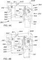
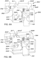
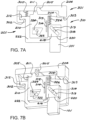
- FIGS. 3A and 3B , FIGS. 4A and 4B , FIGS. 5A and 5B , FIGS. 6A and 6B , and FIGS. 7A and 7B schematically illustrate the operative relationships of the various components of latch release mechanism 201, at sequential stages of the operation of latch release mechanism 201.
- latch release mechanism 201 is a three-dimensional rotary assembly, to facilitate a clear understanding of the structure and operation of latch release mechanism 201, the basic components of latch release mechanism 201 are shown in FIGS. 3A to 7B in a generally two-dimensional schematic manner, with the tangential (rotary) direction being transposed into the horizontal direction, and with the axial direction being transposed into the vertical direction.
- FIGS. 3A and 3B illustrate latch release mechanism 201 in relation to a schematically-represented CRT, still in the fully-latched position, with a schematically-represented tubular workpiece 101 disposed slightly below movable bumper 218.
- Reference number 301 represents an upper latch assembly rigidly coupled to body assembly 110 of the CRT, and having a trigger reaction dog pocket 205 and an upper rotary latch receiver 302.
- Reference number 310 represents a lower latch assembly comprising a cage extension 222 incorporating a lower rotary latch hook 312 shown in the latched position relative to upper rotary latch receiver 302.
- Upper latch assembly 301 carries an internal upper cam ramp surface 303, shown nearly in contact with an internal lower cam ramp surface 304 on cage extension 222, with an internal biasing spring 305 disposed and acting between body assembly 110 and cage extension 222. These features are shown to represent the internal reactions and forces operative between body assembly 110 and grip assembly 120 of the CRT, to facilitate an understanding the functioning of the CRT in coordination with latch release mechanism 201.
- Cage extension 222 carries a movable bumper 218 having a movable land surface 220 and a trigger element 210.
- Movable bumper 218 is linked to trigger element 210 by a bumper-trigger cam follower 314 rigidly fixed to movable bumper 218 and movable within an axially-oriented bumper-trigger cam slot 315 formed in trigger element 210, such that movable bumper 218 is axially-movable relative to trigger element 210.
- a bumper-cage cam follower 318 rigidly fixed to cage extension 222, is constrained to move within a bumper-cage cam slot 319 formed in movable bumper 218 (with bumper-cage cam slot 319 having an upper end 320 and a lower end 321); and a trigger-cage cam follower 322, rigidly fixed to cage extension 222, is constrained to move within a trigger-cage cam pocket 324 provided in trigger element 210.
- bumper-trigger cam slot 315 is provided as an axially-oriented slot, closely fitting with the diameter of the associated bumper-trigger cam follower 314, and thus having a single degree of freedom to permit only relative axial sliding movement between trigger element 210 and movable bumper 218 but not relative rotation, with a trigger bias spring 326 being provided to act between trigger element 210 and movable bumper 218, in the direction of axial sliding, to bias movable bumper 218 downward relative to trigger element 210.
- Bumper-cage cam slot 319 is sloped at a selected angle relative to the vertical (shown by way of non-limiting example in FIGS.
- trigger-cage cam follower 322 is permitted within the trapezoidal trigger-cage cam pocket 324, constrained only by contact against cam constraint surfaces defining the perimeter of trigger-cage cam pocket 324, as follows:
- latch release mechanism 201 may be characterized with reference to the position of trigger-cage cam follower 322 within trigger-cage pocket 324, as follows:
- trigger spring 326 maintains the engagement of trigger dog tooth 211 within trigger reaction dog pocket 205, which engagement can position trigger dog tooth lock flank 214 in close opposition with lock flank 208 of trigger reaction dog pocket 205, as in this illustrated embodiment, so as to prevent accidental rotation of upper rotary latch assembly 301 relative to lower rotary latch assembly 310 as controlled by the selection of the mating flank angle and gap. Where a more vertically-inclined angle is selected to more strongly resist rotation for a given trigger bias spring 326 force.
- the trigger dog tooth lock flank 214 and mating reaction pocket lock flank 208 provide the additional benefit of protection against accidental rotation.
- mating latch hook 312 and latch receiver 302 can be alternatively configured to disengage in response to applied torque only.
- movable bumper 218 Independent of whether the applied load is first sufficient to overcome the force of the internal bias spring, when sufficient force is applied by workpiece 101 to overcome the force of trigger bias spring 326, movable bumper 218 will move upward, causing bumper-cage cam follower 318 to move downward within sloped bumper-cage cam slot 319, as shown in FIGS. 5A and 5B .
- the upward movement of movable bumper 218 tends to cause rotation of cage extension 222, but such rotation is resisted by the actuation torque acting between upper latch assembly 301 and lower latch assembly 301 and 310.
- This torque is transferred through movable bumper 218 to trigger element 210 via bumper-trigger cam follower 318 and cam slot 319, and through trigger dog tooth load flank 212 to reaction pocket load flank 206 and thence back to upper latch assembly 301, thus internally reacting the latch actuation torque and causing trigger-cage cam follower 322 to move along trigger advance cam surface 330 to the advanced position within trigger-cam pocket 324, thus moving the rotary latch to its unlatched position as shown in FIGS. 5A and 5B .
- This movement is illustrated as right-hand rotation of upper latch assembly 301 relative to lower latch assembly 310.
- trigger-cage cam follower 322 As may be seen with reference to FIGS. 6A and 6B , further upward movement of movable bumper 218 continues to urge rotation of cage extension 222, causing movement of trigger-cage cam follower 322 to the withdrawn position within trigger-cam pocket 324, resultant downward movement of trigger element 210, and corresponding withdrawal of trigger dog tooth 211 from engagement with trigger reaction dog pocket 205.
- the slope angle of trigger withdraw cam surface 332 of trigger-cam pocket 324 is selected relative to the orientation of bumper-cage cam slot 319 to promote the withdrawal of trigger dog tooth 211 without jamming or otherwise inducing excess force considering the operative trigger bias spring 326 force and frictional forces otherwise tending to affect the withdrawal movement.
- upper rotary latch assembly 301 is free to rotate relative to the lower rotary latch assembly 310, and, more specifically, allows left-hand rotation of upper latch assembly 301 relative to lower latch assembly 310 to re-latch the tool.
- trigger bias spring 326 urges movable bumper 218 downward and correspondingly causing rotation of movable bumper 218 relative to cage extension 222, possibly with associated sliding at the interface between movable land surface 220 and tubular workpiece 101, and resultant tractional frictional force acting in the direction to maintain latching.
- This movement of movable bumper 218 and the force from trigger bias spring 326 tend to urge trigger element 210 to reverse the withdrawal movement just described, moving trigger dog tooth 211 upward.
- trigger dog tooth crest 213 slidingly engages reaction pocket crest 207, forcing trigger-cage cam follower 322 to move from the withdrawn position toward the reset position within trigger-cage cam pocket 324.
- movable bumper 218 continues to move downward, following the movement of workpiece 101, a point is reached where trigger dog tooth crest 213 no longer engages (i.e., slides off) reaction pocket crest 207, thereby allowing trigger-cage cam follower 322 to move from the reset position and back toward the start position within trigger-cage cam pocket 324, thus returning the latch release mechanism 201 to the operational state shown in FIGS. 3A and 3B , in which the tool is once again ready to initiate the operational sequence illustrated in FIGS. 3A and 3B through 7A and 7B .
- FIG. 2B illustrates an internally-gripping casing running tool (CRTi) 130 modified to incorporate an exemplary embodiment of a latch release mechanism 131 in accordance with the present disclosure, and a tri-cam latching linkage 132 generally as disclosed in U.S. Patent No. 7,909,120 .
- FIGS. 8A and 8B , FIGS. 9A and 9B , FIGS. 10A and 10B , and FIGS. 11A and 11B illustrate sequential operational stages of latch release mechanism 131.
- modified CRTi 130 comprises a body assembly 110 incorporating a mandrel 111 having a load adaptor 112 for structural connection to the top drive quill of a drilling rig (not shown), a grip assembly 120 comprising a cage 500 and jaws 123, latch release mechanism 131, and tri-cam latching linkage 132.
- Tri-cam latching linkage 132 comprises an upper latch assembly 133 fixed to and carried by body assembly 110, and a lower latch assembly 134 fixed to and carried by grip assembly 120.
- latch release mechanism 131 includes an upper latch assembly 133 comprising a drive cam body 400 carrying a plurality of drive cam latch hooks 401, and a drive cam housing 420, with drive cam body 400 being rigidly constrained to body assembly 110 of CRTi 130.
- Latch release mechanism 131 further includes a lower latch assembly 134 comprising a driven cam body 470, a driven cam housing 480, and a latch cam 490, with latch cam 490 having a plurality of latch cam latch hooks 491, and being rigidly constrained to grip assembly 120 of CRTi 130.
- a drive cam body-housing seal 403, a drive cam body-mandrel seal 404, a drive housing-driven housing seal 421, a drive cam body-cage seal 472, and a cage mandrel seal 501 define an annular piston area and a gas spring chamber 422.
- gas spring chamber 422 forms an internal gas spring that tends to urge the separation of upper latch assembly 133 and lower latch assembly 134, thereby tending to urge separation of body assembly 110 and grip assembly 120 to move latch release mechanism 131 between a first (unlatched) position and a second (latched) position.
- Tri-cam latching linkage 132 is considered to be in the latched position when drive cam latch hooks 401 and latch cam latch hooks 491 are engaged, and in the unlatched position when drive cam latch hooks 401 and latch cam latch hooks 491 are disengaged.
- FIG. 8B is a cross-section through latch release mechanism 131 shown in the latched position.
- the body assembly 110 will be considered as the datum, and the tubular workpiece 101 will be viewed as tending to move upward.
- CRTi 130 with latch release mechanism 131 would first be inserted or "stabbed” into tubular workpiece 101 and lowered until movable land surface 451 contacts tubular workpiece 101, and the contact force resulting from tool weight and set-down load applied by the top drive (not shown) increases above the "trigger set-down load", at which point latch release mechanism 131 has applied the required latch actuation torque and the displacement required to disengage drive cam latch hooks 401 and latch cam latch hooks 491.
- the gas spring will cause axial displacement of body assembly 110 relative to grip assembly 120, transitioning the CRTi tool 130 with latch release mechanism 131 from the retracted position to the engaged position.
- This operational sequence differs from prior art CRTi 100 in two ways:
- cam follower can be fixed to either of the two components to be paired, with the cam profile defined in the other of the two paired components, and that the design choice in this regard will typically be based on practical considerations such as efficient assembly, disassembly and maintenance.
- design choice in this regard will typically be based on practical considerations such as efficient assembly, disassembly and maintenance.
- cam follower/cam surface as the means for providing the desired movement constraint is not intended to be in any way limiting, where persons skilled in the art will understand generally equivalent linkages can be provided in other forms.
- trigger cam slot 445 is provided as an axially-oriented slot, closely fitting with bumper cam follower 452, and thus generally providing a single degree of freedom to permit relative axial movement between trigger element 440 and movable bumper 450, but not permitting relative rotation.
- Trigger bias spring 449 is provided to act between trigger element 440 and movable bumper 450 in the direction of axial sliding, to bias movable bumper 450 downward.
- Bumper-cage cam slot 461 is sloped at a selected angle relative to the vertical (shown by way of non-limiting example in FIG.
- latch release mechanism 131 may be characterized with reference to the position of trigger cam follower 448 within trigger-cage pocket 424, as follows:
- trigger bias spring 449 will urge trigger cam follower 448 toward the start position within cage cam pocket 464, while simultaneously maintaining the engagement of trigger dog teeth 441 within corresponding trigger reaction dog pockets 411.
- This engagement of trigger dog teeth 441 disposes trigger dog tooth lock flanks 444 in close opposition to corresponding reaction pocket lock flanks 414 so as to prevent accidental rotation of upper latch assembly 133 relative to lower latch assembly 134 as controlled by the selection of the mating flank angle and gap. If necessary, a more axially-aligned camming surface may be selected to more strongly resist rotation for a given force exerted by trigger bias spring 449.
- the angle of withdraw cam surface 467 relative to sloped cage cam slot 461 may be selected so as to promote the withdrawal of trigger dog teeth 441 from engagement with trigger reaction dog pockets 411 without jamming or otherwise inducing force in excess of the operative trigger bias force and frictional forces otherwise tending to affect the withdrawal movement.
- trigger dog tooth lock flank 444 is no longer opposite reaction pocket load flank 412, so upper latch assembly 133 can be rotated relative to lower latch assembly 134 in order to re-latch tri-cam latching linkage 132.
- this rotation of upper latch assembly 133 relative to lower latch assembly 134 causes latch cam latch hooks 491 to move into engagement with drive cam latch hooks 401 (i.e., the latched position), with the corresponding actuation torque induced by this rotation being resisted by tractional engagement of movable land surface 451 with tubular workpiece 101.
- trigger bias spring 449 urges movable bumper 450 downward and correspondingly causes movable bumper 450 to rotate relative to cage extension 460, with possible attendant sliding between movable land surface 451 and tubular workpiece 101. Tractional frictional force from trigger bias spring 449 thus tends to urge trigger element 440 to reverse the withdrawal movement described above, moving trigger dog teeth 441 upward.
- trigger dog teeth 441 is prevented by sliding engagement of trigger dog tooth crests 443 with reaction pocket crest 413, forcing trigger cam follower 448 to move from the withdrawn position to the reset position within cage cam pocket 464.
- movable bumper 450 continues to move downward, following the movement of tubular workpiece 101, a point is reached where trigger dog tooth crests 443 no longer engage (i.e., they slide off) reaction pocket crest 413, thereby allowing trigger cam follower 448 to move from the reset position to the start position within cage cam pocket 464, thus returning latch release mechanism 131 to the position shown in FIG. 8A , from which position the operational sequence shown in FIGS. 8A to 11B can be repeated.
- any form of the word “comprise” is to be understood in its non-limiting sense to mean that any item following such word is included, but items not specifically mentioned are not excluded.
- a reference to an element by the indefinite article “a” does not exclude the possibility that more than one of the element is present, unless the context clearly requires that there be one and only one such element.
- Any use of any form of the terms “connect”, “engage”, “couple”, “latch”, “attach”, or any other term describing an interaction between elements is not meant to limit the interaction to direct interaction between the subject elements, and may also include indirect interaction between the elements such as through secondary or intermediary structure.
Landscapes
- Engineering & Computer Science (AREA)
- Geology (AREA)
- Mining & Mineral Resources (AREA)
- Life Sciences & Earth Sciences (AREA)
- General Life Sciences & Earth Sciences (AREA)
- Fluid Mechanics (AREA)
- Environmental & Geological Engineering (AREA)
- Physics & Mathematics (AREA)
- Geochemistry & Mineralogy (AREA)
- Mechanical Engineering (AREA)
- Earth Drilling (AREA)
- Percussive Tools And Related Accessories (AREA)
- Clamps And Clips (AREA)
- Lock And Its Accessories (AREA)
- Portable Nailing Machines And Staplers (AREA)
- Jigs For Machine Tools (AREA)
- Lift-Guide Devices, And Elevator Ropes And Cables (AREA)
Claims (13)
- Mécanisme (201) comprenant :(a) un ensemble verrou supérieur (301) et un ensemble verrou inférieur (310), lesdits ensembles verrous supérieur et inférieur étant en alignement axial avec un axe longitudinal du mécanisme ;(b) un élément de verrou rotatif supérieur (204) porté sur et couplé en rotation à l'ensemble verrou supérieur, et un élément de verrou inférieur (222) porté sur et couplé en rotation à l'ensemble verrou inférieur ;(c) un élément butoir (218) définissant une surface d'appui orientée vers le bas (220), ledit élément butoir étant couplé à l'ensemble verrou inférieur de façon à pouvoir se déplacer à la fois axialement et en rotation par rapport à l'ensemble verrou inférieur ; et(d) un élément déclencheur (210) couplé à l'élément butoir et à l'ensemble verrou inférieur de façon à pouvoir se déplacer au moins axialement par rapport à l'élément butoir et de façon à pouvoir se déplacer axialement et en rotation par rapport à l'ensemble verrou inférieur ;dans lequel :(e) les éléments de verrou rotatifs supérieur et inférieur sont conçus pour se déplacer d'une position verrouillée axialement à une position déverrouillée axialement en réponse à la rotation relative entre les éléments de verrou rotatifs supérieur et inférieur dans une première direction de rotation ;(f) l'ensemble verrou supérieur définit une ou plusieurs poches à taquet de réaction de déclenchement orientées vers le bas (205) ; et(g) l'élément de déclenchement définit un ou plusieurs taquets de déclenchement orientés vers le haut (211) conçus pour venir en prise avec la ou les poches à taquet de réaction de déclenchement de l'ensemble verrou supérieur ;de sorte que lorsque le ou les taquets de déclenchement sont disposés à l'intérieur de la ou des poches à taquet de réaction de déclenchement, une force verticale appliquée à la surface d'appui de l'élément butoir tend à provoquer un déplacement relatif axial vers le haut de l'élément butoir provoquant la rotation de l'ensemble verrou inférieur, l'élément déclencheur agissant entre l'élément butoir et par une prise des taquets de déclenchement avec l'ensemble verrou supérieur pour forcer la rotation relative entre les éléments de verrou rotatifs supérieur et inférieur pour induire un dégagement axial des éléments de verrou rotatifs supérieur et inférieur, de façon que l'application continue de la force verticale et du déplacement axial et rotatif résultant de l'élément butoir par rapport à l'ensemble verrou inférieur provoque le retrait du ou des taquets de déclenchement de la ou des poches à taquet de réaction de déclenchement.
- Mécanisme selon la revendication 1, dans lequel l'élément butoir est mobile axialement par rapport à l'élément déclencheur au moyen d'un premier élément suiveur (314) couplé de façon rigide à l'élément butoir et disposé de façon mobile à l'intérieur d'une fente orientée axialement (315) dans l'élément déclencheur.
- Mécanisme selon la revendication 2, comprenant en outre un deuxième élément suiveur (322) couplé de façon rigide à l'ensemble verrou inférieur et disposé de façon mobile à l'intérieur d'une poche (324) formée dans l'élément déclencheur, de façon que la plage de déplacement axial et rotatif de l'élément déclencheur par rapport à l'ensemble verrou inférieur soit définie par la configuration de ladite poche formée dans l'élément déclencheur.
- Mécanisme selon la revendication 3, dans lequel la poche formée dans l'élément déclencheur présente une configuration trapézoïdale.
- Mécanisme selon l'une quelconque des revendications 1 à 4, comprenant en outre un troisième élément suiveur (318) couplé de façon rigide à l'ensemble verrou inférieur et disposé de façon mobile à l'intérieur d'une came à rainure de butée de déclenchement (319) formée dans l'élément butoir, de façon que la plage de déplacement axial et rotatif de l'élément butoir par rapport à l'ensemble verrou inférieur soit définie par la configuration de la came à rainure de butée de déclenchement.
- Mécanisme selon la revendication 5, dans lequel la came à rainure de butée de déclenchement est configurée en une fente allongée présentant une pente par rapport à la verticale.
- Mécanisme selon la revendication 6, dans lequel la came à rainure de butée de déclenchement est pentue selon un angle de 45 degrés par rapport à la verticale.
- Mécanisme selon l'une quelconque des revendications 1 à 7, comprenant en outre :(a) un premier moyen de polarisation orienté axialement (305), agissant entre les ensembles verrous supérieur et inférieur de façon à polariser le mécanisme de libération de verrou en direction de la position verrouillée ; et(b) un second moyen de polarisation orienté axialement (326), agissant entre l'élément butoir mobile et l'élément déclencheur de façon à polariser l'élément butoir axialement vers le bas par rapport à l'élément déclencheur.
- Mécanisme selon l'une quelconque des revendications 1 à 8, dans lequel l'ensemble verrou supérieur comprend l'ensemble de corps principal d'un outil de pose de tubage (CRT) (130) et l'ensemble verrou inférieur comprend l'ensemble de saisie du CRT.
- Mécanisme selon la revendication 9, dans lequel l'ensemble verrou inférieur comprend une extension de cage couplée de façon rigide à la cage de l'ensemble de saisie (120) du CRT, et dans lequel les deuxième et troisième éléments suiveurs sont fixés à l'extension de cage.
- Mécanisme selon la revendication 10, dans lequel l'extension de cage, l'élément déclencheur et le butoir mobile sont conçus en tant que groupe imbriqué coaxialement d'éléments cylindriques étroitement ajustés, où les mouvements relatifs rotatifs et de translation entre ces composants sont contraints pour les maintenir alignés coaxialement.
- Mécanisme selon l'une quelconque des revendications 1 à 11, dans lequel :(a) l'ensemble verrou supérieur définit une surface de rampe supérieure orientée vers le bas (303) ; et(b) l'ensemble verrou inférieur définit une surface de rampe inférieure orientée vers le haut (304) pouvant venir en prise coulissante avec la surface de rampe supérieure.
- Mécanisme selon la revendication 12, conçu de telle sorte que l'application d'une force verticale sur la surface d'appui de l'élément butoir amène les surfaces de rampe supérieure et inférieure en prise coulissante de façon à contraindre l'approche axiale relative des ensembles verrous supérieur et inférieur tout en permettant une rotation relative entre les ensembles verrous supérieur et inférieur.
Applications Claiming Priority (2)
| Application Number | Priority Date | Filing Date | Title |
|---|---|---|---|
| US201762535062P | 2017-07-20 | 2017-07-20 | |
| PCT/CA2018/000144 WO2019014747A1 (fr) | 2017-07-20 | 2018-07-20 | Mécanisme de déblocage de verrou rotatif actionné par charge axiale |
Publications (4)
| Publication Number | Publication Date |
|---|---|
| EP3655619A1 EP3655619A1 (fr) | 2020-05-27 |
| EP3655619A4 EP3655619A4 (fr) | 2021-03-24 |
| EP3655619B1 true EP3655619B1 (fr) | 2024-01-03 |
| EP3655619C0 EP3655619C0 (fr) | 2024-01-03 |
Family
ID=65014935
Family Applications (1)
| Application Number | Title | Priority Date | Filing Date |
|---|---|---|---|
| EP18834590.4A Active EP3655619B1 (fr) | 2017-07-20 | 2018-07-20 | Mécanisme de déblocage de verrou rotatif actionné par charge axiale |
Country Status (8)
| Country | Link |
|---|---|
| US (1) | US11299940B2 (fr) |
| EP (1) | EP3655619B1 (fr) |
| CN (1) | CN110832165B (fr) |
| AU (1) | AU2018303848B2 (fr) |
| CA (1) | CA3067901C (fr) |
| RU (1) | RU2020107408A (fr) |
| SA (1) | SA520411087B1 (fr) |
| WO (1) | WO2019014747A1 (fr) |
Families Citing this family (6)
| Publication number | Priority date | Publication date | Assignee | Title |
|---|---|---|---|---|
| US11313183B2 (en) | 2019-01-19 | 2022-04-26 | Noetic Technologies Inc. | Axial-load-actuated rotary latch release mechanisms for casing running tools |
| US11332985B1 (en) | 2020-02-07 | 2022-05-17 | Noetic Technologies Inc. | Lockout mechanism for gripping tool |
| MX2023004868A (es) * | 2020-10-26 | 2023-05-10 | Noetic Tech Inc | Enganche axial de longitud variable para herramientas de corrida de tubulares. |
| AR129183A1 (es) * | 2022-05-02 | 2024-07-24 | Noetic Tech Inc | Mecanismo de liberación de enganche |
| US20250087047A1 (en) * | 2023-09-13 | 2025-03-13 | Aristocrat Technologies, Inc. | Dual-latch mechanism |
| US20250320784A1 (en) * | 2024-04-10 | 2025-10-16 | Keller North America, Inc. | Collapsible casing tightener and method of use |
Family Cites Families (10)
| Publication number | Priority date | Publication date | Assignee | Title |
|---|---|---|---|---|
| US2028966A (en) * | 1934-05-07 | 1936-01-28 | Burns Erwin | Releasing overshot |
| US7909120B2 (en) * | 2005-05-03 | 2011-03-22 | Noetic Technologies Inc. | Gripping tool |
| RU2503792C2 (ru) * | 2008-07-18 | 2014-01-10 | Ноэтик Текнолоджиз Инк. | Механизм управления выдвижением захвата для создания захватывающего инструмента с увеличенным рабочим диапазоном и способ его использования |
| US9010433B2 (en) * | 2010-07-16 | 2015-04-21 | Weatherford Technology Holdings, Llc | Positive retraction latch locking dog for a rotating control device |
| GB201014088D0 (en) * | 2010-08-23 | 2010-10-06 | Aker Subsea Ltd | Subsea running tool with emergency release |
| US8739888B2 (en) * | 2011-04-28 | 2014-06-03 | Tesco Corporation | Mechanically actuated casing drive system tool |
| WO2014056092A1 (fr) * | 2012-10-09 | 2014-04-17 | Noetic Technologies Inc. | Outil d'accrochage d'éléments tubulaires |
| US9631442B2 (en) | 2013-12-19 | 2017-04-25 | Weatherford Technology Holdings, Llc | Heave compensation system for assembling a drill string |
| US10077620B2 (en) * | 2014-09-26 | 2018-09-18 | Cameron International Corporation | Load shoulder system |
| CN106812480B (zh) | 2017-03-24 | 2019-02-15 | 成都市卓新实业有限公司 | 一种防脱防单吊环起吊系统 |
-
2018
- 2018-07-20 US US16/624,684 patent/US11299940B2/en active Active
- 2018-07-20 EP EP18834590.4A patent/EP3655619B1/fr active Active
- 2018-07-20 CA CA3067901A patent/CA3067901C/fr active Active
- 2018-07-20 WO PCT/CA2018/000144 patent/WO2019014747A1/fr not_active Ceased
- 2018-07-20 CN CN201880045208.1A patent/CN110832165B/zh active Active
- 2018-07-20 AU AU2018303848A patent/AU2018303848B2/en active Active
- 2018-07-20 RU RU2020107408A patent/RU2020107408A/ru unknown
-
2020
- 2020-01-19 SA SA520411087A patent/SA520411087B1/ar unknown
Also Published As
| Publication number | Publication date |
|---|---|
| RU2020107408A3 (fr) | 2021-11-18 |
| SA520411087B1 (ar) | 2022-10-08 |
| AU2018303848A1 (en) | 2020-02-06 |
| US20200131864A1 (en) | 2020-04-30 |
| RU2020107408A (ru) | 2021-08-20 |
| EP3655619A1 (fr) | 2020-05-27 |
| US11299940B2 (en) | 2022-04-12 |
| EP3655619A4 (fr) | 2021-03-24 |
| CN110832165A (zh) | 2020-02-21 |
| AU2018303848B2 (en) | 2023-06-08 |
| WO2019014747A1 (fr) | 2019-01-24 |
| CN110832165B (zh) | 2021-08-10 |
| EP3655619C0 (fr) | 2024-01-03 |
| CA3067901A1 (fr) | 2019-01-24 |
| CA3067901C (fr) | 2023-01-31 |
Similar Documents
| Publication | Publication Date | Title |
|---|---|---|
| EP3655619B1 (fr) | Mécanisme de déblocage de verrou rotatif actionné par charge axiale | |
| US20220243541A1 (en) | Axial-load-actuated rotary latch release mechanisms for casing running tools | |
| EP2313600B1 (fr) | Extension axiale a triple came pour constituer un outil de saisie avec une capacite et une plage de fonctionnement ameliorees | |
| US20220259930A1 (en) | Internal latch release mechanism for externally-gripping casing running tools | |
| NL8104396A (nl) | Terugneembare putinrichting. | |
| US12168907B1 (en) | Latch release mechanism | |
| CA3261895C (fr) | Mécanisme d'embrayage pour outils de préhension | |
| HK1155788B (en) | Tricam axial extension to provide gripping tool with improved operational range and capacity | |
| AU2023371484A1 (en) | Clutch mechanism for gripping tools |
Legal Events
| Date | Code | Title | Description |
|---|---|---|---|
| STAA | Information on the status of an ep patent application or granted ep patent |
Free format text: STATUS: THE INTERNATIONAL PUBLICATION HAS BEEN MADE |
|
| PUAI | Public reference made under article 153(3) epc to a published international application that has entered the european phase |
Free format text: ORIGINAL CODE: 0009012 |
|
| STAA | Information on the status of an ep patent application or granted ep patent |
Free format text: STATUS: REQUEST FOR EXAMINATION WAS MADE |
|
| 17P | Request for examination filed |
Effective date: 20200206 |
|
| AK | Designated contracting states |
Kind code of ref document: A1 Designated state(s): AL AT BE BG CH CY CZ DE DK EE ES FI FR GB GR HR HU IE IS IT LI LT LU LV MC MK MT NL NO PL PT RO RS SE SI SK SM TR |
|
| AX | Request for extension of the european patent |
Extension state: BA ME |
|
| DAV | Request for validation of the european patent (deleted) | ||
| DAX | Request for extension of the european patent (deleted) | ||
| REG | Reference to a national code |
Ref country code: DE Ref legal event code: R079 Free format text: PREVIOUS MAIN CLASS: E21B0019060000 Ref country code: DE Ref legal event code: R079 Ref document number: 602018063721 Country of ref document: DE Free format text: PREVIOUS MAIN CLASS: E21B0019060000 Ipc: E21B0003020000 |
|
| REG | Reference to a national code |
Ref country code: HK Ref legal event code: DE Ref document number: 40031088 Country of ref document: HK |
|
| A4 | Supplementary search report drawn up and despatched |
Effective date: 20210219 |
|
| RIC1 | Information provided on ipc code assigned before grant |
Ipc: E21B 19/06 20060101ALI20210215BHEP Ipc: E21B 3/02 20060101AFI20210215BHEP Ipc: E21B 23/00 20060101ALI20210215BHEP Ipc: E21B 19/16 20060101ALI20210215BHEP |
|
| STAA | Information on the status of an ep patent application or granted ep patent |
Free format text: STATUS: EXAMINATION IS IN PROGRESS |
|
| 17Q | First examination report despatched |
Effective date: 20220715 |
|
| GRAP | Despatch of communication of intention to grant a patent |
Free format text: ORIGINAL CODE: EPIDOSNIGR1 |
|
| STAA | Information on the status of an ep patent application or granted ep patent |
Free format text: STATUS: GRANT OF PATENT IS INTENDED |
|
| INTG | Intention to grant announced |
Effective date: 20230807 |
|
| RIN1 | Information on inventor provided before grant (corrected) |
Inventor name: SLACK, MAURICE WILLIAM |
|
| GRAS | Grant fee paid |
Free format text: ORIGINAL CODE: EPIDOSNIGR3 |
|
| GRAA | (expected) grant |
Free format text: ORIGINAL CODE: 0009210 |
|
| STAA | Information on the status of an ep patent application or granted ep patent |
Free format text: STATUS: THE PATENT HAS BEEN GRANTED |
|
| AK | Designated contracting states |
Kind code of ref document: B1 Designated state(s): AL AT BE BG CH CY CZ DE DK EE ES FI FR GB GR HR HU IE IS IT LI LT LU LV MC MK MT NL NO PL PT RO RS SE SI SK SM TR |
|
| REG | Reference to a national code |
Ref country code: GB Ref legal event code: FG4D |
|
| REG | Reference to a national code |
Ref country code: DE Ref legal event code: R096 Ref document number: 602018063721 Country of ref document: DE |
|
| REG | Reference to a national code |
Ref country code: CH Ref legal event code: EP |
|
| REG | Reference to a national code |
Ref country code: IE Ref legal event code: FG4D |
|
| U01 | Request for unitary effect filed |
Effective date: 20240104 |
|
| U07 | Unitary effect registered |
Designated state(s): AT BE BG DE DK EE FI FR IT LT LU LV MT NL PT SE SI Effective date: 20240116 |
|
| PG25 | Lapsed in a contracting state [announced via postgrant information from national office to epo] |
Ref country code: ES Free format text: LAPSE BECAUSE OF FAILURE TO SUBMIT A TRANSLATION OF THE DESCRIPTION OR TO PAY THE FEE WITHIN THE PRESCRIBED TIME-LIMIT Effective date: 20240103 |
|
| PG25 | Lapsed in a contracting state [announced via postgrant information from national office to epo] |
Ref country code: ES Free format text: LAPSE BECAUSE OF FAILURE TO SUBMIT A TRANSLATION OF THE DESCRIPTION OR TO PAY THE FEE WITHIN THE PRESCRIBED TIME-LIMIT Effective date: 20240103 |
|
| PG25 | Lapsed in a contracting state [announced via postgrant information from national office to epo] |
Ref country code: IS Free format text: LAPSE BECAUSE OF FAILURE TO SUBMIT A TRANSLATION OF THE DESCRIPTION OR TO PAY THE FEE WITHIN THE PRESCRIBED TIME-LIMIT Effective date: 20240503 |
|
| PG25 | Lapsed in a contracting state [announced via postgrant information from national office to epo] |
Ref country code: GR Free format text: LAPSE BECAUSE OF FAILURE TO SUBMIT A TRANSLATION OF THE DESCRIPTION OR TO PAY THE FEE WITHIN THE PRESCRIBED TIME-LIMIT Effective date: 20240404 |
|
| PG25 | Lapsed in a contracting state [announced via postgrant information from national office to epo] |
Ref country code: HR Free format text: LAPSE BECAUSE OF FAILURE TO SUBMIT A TRANSLATION OF THE DESCRIPTION OR TO PAY THE FEE WITHIN THE PRESCRIBED TIME-LIMIT Effective date: 20240103 Ref country code: RS Free format text: LAPSE BECAUSE OF FAILURE TO SUBMIT A TRANSLATION OF THE DESCRIPTION OR TO PAY THE FEE WITHIN THE PRESCRIBED TIME-LIMIT Effective date: 20240403 |
|
| PG25 | Lapsed in a contracting state [announced via postgrant information from national office to epo] |
Ref country code: CZ Free format text: LAPSE BECAUSE OF FAILURE TO SUBMIT A TRANSLATION OF THE DESCRIPTION OR TO PAY THE FEE WITHIN THE PRESCRIBED TIME-LIMIT Effective date: 20240103 |
|
| PG25 | Lapsed in a contracting state [announced via postgrant information from national office to epo] |
Ref country code: RS Free format text: LAPSE BECAUSE OF FAILURE TO SUBMIT A TRANSLATION OF THE DESCRIPTION OR TO PAY THE FEE WITHIN THE PRESCRIBED TIME-LIMIT Effective date: 20240403 Ref country code: IS Free format text: LAPSE BECAUSE OF FAILURE TO SUBMIT A TRANSLATION OF THE DESCRIPTION OR TO PAY THE FEE WITHIN THE PRESCRIBED TIME-LIMIT Effective date: 20240503 Ref country code: HR Free format text: LAPSE BECAUSE OF FAILURE TO SUBMIT A TRANSLATION OF THE DESCRIPTION OR TO PAY THE FEE WITHIN THE PRESCRIBED TIME-LIMIT Effective date: 20240103 Ref country code: GR Free format text: LAPSE BECAUSE OF FAILURE TO SUBMIT A TRANSLATION OF THE DESCRIPTION OR TO PAY THE FEE WITHIN THE PRESCRIBED TIME-LIMIT Effective date: 20240404 Ref country code: CZ Free format text: LAPSE BECAUSE OF FAILURE TO SUBMIT A TRANSLATION OF THE DESCRIPTION OR TO PAY THE FEE WITHIN THE PRESCRIBED TIME-LIMIT Effective date: 20240103 |
|
| PG25 | Lapsed in a contracting state [announced via postgrant information from national office to epo] |
Ref country code: PL Free format text: LAPSE BECAUSE OF FAILURE TO SUBMIT A TRANSLATION OF THE DESCRIPTION OR TO PAY THE FEE WITHIN THE PRESCRIBED TIME-LIMIT Effective date: 20240103 |
|
| U20 | Renewal fee for the european patent with unitary effect paid |
Year of fee payment: 7 Effective date: 20240716 |
|
| PG25 | Lapsed in a contracting state [announced via postgrant information from national office to epo] |
Ref country code: PL Free format text: LAPSE BECAUSE OF FAILURE TO SUBMIT A TRANSLATION OF THE DESCRIPTION OR TO PAY THE FEE WITHIN THE PRESCRIBED TIME-LIMIT Effective date: 20240103 |
|
| REG | Reference to a national code |
Ref country code: DE Ref legal event code: R097 Ref document number: 602018063721 Country of ref document: DE |
|
| PG25 | Lapsed in a contracting state [announced via postgrant information from national office to epo] |
Ref country code: SM Free format text: LAPSE BECAUSE OF FAILURE TO SUBMIT A TRANSLATION OF THE DESCRIPTION OR TO PAY THE FEE WITHIN THE PRESCRIBED TIME-LIMIT Effective date: 20240103 |
|
| PG25 | Lapsed in a contracting state [announced via postgrant information from national office to epo] |
Ref country code: SK Free format text: LAPSE BECAUSE OF FAILURE TO SUBMIT A TRANSLATION OF THE DESCRIPTION OR TO PAY THE FEE WITHIN THE PRESCRIBED TIME-LIMIT Effective date: 20240103 |
|
| PG25 | Lapsed in a contracting state [announced via postgrant information from national office to epo] |
Ref country code: SM Free format text: LAPSE BECAUSE OF FAILURE TO SUBMIT A TRANSLATION OF THE DESCRIPTION OR TO PAY THE FEE WITHIN THE PRESCRIBED TIME-LIMIT Effective date: 20240103 Ref country code: SK Free format text: LAPSE BECAUSE OF FAILURE TO SUBMIT A TRANSLATION OF THE DESCRIPTION OR TO PAY THE FEE WITHIN THE PRESCRIBED TIME-LIMIT Effective date: 20240103 |
|
| PLBE | No opposition filed within time limit |
Free format text: ORIGINAL CODE: 0009261 |
|
| STAA | Information on the status of an ep patent application or granted ep patent |
Free format text: STATUS: NO OPPOSITION FILED WITHIN TIME LIMIT |
|
| 26N | No opposition filed |
Effective date: 20241007 |
|
| PG25 | Lapsed in a contracting state [announced via postgrant information from national office to epo] |
Ref country code: MC Free format text: LAPSE BECAUSE OF FAILURE TO SUBMIT A TRANSLATION OF THE DESCRIPTION OR TO PAY THE FEE WITHIN THE PRESCRIBED TIME-LIMIT Effective date: 20240103 |
|
| REG | Reference to a national code |
Ref country code: CH Ref legal event code: PL |
|
| PG25 | Lapsed in a contracting state [announced via postgrant information from national office to epo] |
Ref country code: CH Free format text: LAPSE BECAUSE OF NON-PAYMENT OF DUE FEES Effective date: 20240731 |
|
| PGFP | Annual fee paid to national office [announced via postgrant information from national office to epo] |
Ref country code: NO Payment date: 20250625 Year of fee payment: 8 |
|
| PG25 | Lapsed in a contracting state [announced via postgrant information from national office to epo] |
Ref country code: IE Free format text: LAPSE BECAUSE OF NON-PAYMENT OF DUE FEES Effective date: 20240720 |
|
| U20 | Renewal fee for the european patent with unitary effect paid |
Year of fee payment: 8 Effective date: 20250620 |
|
| PGFP | Annual fee paid to national office [announced via postgrant information from national office to epo] |
Ref country code: GB Payment date: 20250716 Year of fee payment: 8 |
|
| PGFP | Annual fee paid to national office [announced via postgrant information from national office to epo] |
Ref country code: RO Payment date: 20250708 Year of fee payment: 8 |
|
| PG25 | Lapsed in a contracting state [announced via postgrant information from national office to epo] |
Ref country code: CY Free format text: LAPSE BECAUSE OF FAILURE TO SUBMIT A TRANSLATION OF THE DESCRIPTION OR TO PAY THE FEE WITHIN THE PRESCRIBED TIME-LIMIT; INVALID AB INITIO Effective date: 20180720 |
|
| PG25 | Lapsed in a contracting state [announced via postgrant information from national office to epo] |
Ref country code: HU Free format text: LAPSE BECAUSE OF FAILURE TO SUBMIT A TRANSLATION OF THE DESCRIPTION OR TO PAY THE FEE WITHIN THE PRESCRIBED TIME-LIMIT; INVALID AB INITIO Effective date: 20180720 |