EP3655809B1 - Mikroskop, verfahren zum betrieb eines mikroskops und verfahren zur bildgebung einer probe - Google Patents
Mikroskop, verfahren zum betrieb eines mikroskops und verfahren zur bildgebung einer probe Download PDFInfo
- Publication number
- EP3655809B1 EP3655809B1 EP18749735.9A EP18749735A EP3655809B1 EP 3655809 B1 EP3655809 B1 EP 3655809B1 EP 18749735 A EP18749735 A EP 18749735A EP 3655809 B1 EP3655809 B1 EP 3655809B1
- Authority
- EP
- European Patent Office
- Prior art keywords
- sample
- illumination
- light beam
- imaging
- along
- Prior art date
- Legal status (The legal status is an assumption and is not a legal conclusion. Google has not performed a legal analysis and makes no representation as to the accuracy of the status listed.)
- Active
Links
Images

Classifications
-
- G—PHYSICS
- G02—OPTICS
- G02B—OPTICAL ELEMENTS, SYSTEMS OR APPARATUS
- G02B21/00—Microscopes
- G02B21/0004—Microscopes specially adapted for specific applications
- G02B21/002—Scanning microscopes
- G02B21/0024—Confocal scanning microscopes (CSOMs) or confocal "macroscopes"; Accessories which are not restricted to use with CSOMs, e.g. sample holders
- G02B21/0032—Optical details of illumination, e.g. light-sources, pinholes, beam splitters, slits, fibers
-
- G—PHYSICS
- G02—OPTICS
- G02B—OPTICAL ELEMENTS, SYSTEMS OR APPARATUS
- G02B21/00—Microscopes
- G02B21/0004—Microscopes specially adapted for specific applications
- G02B21/002—Scanning microscopes
- G02B21/0024—Confocal scanning microscopes (CSOMs) or confocal "macroscopes"; Accessories which are not restricted to use with CSOMs, e.g. sample holders
- G02B21/0036—Scanning details, e.g. scanning stages
- G02B21/0048—Scanning details, e.g. scanning stages scanning mirrors, e.g. rotating or galvanomirrors, MEMS mirrors
-
- G—PHYSICS
- G02—OPTICS
- G02B—OPTICAL ELEMENTS, SYSTEMS OR APPARATUS
- G02B21/00—Microscopes
- G02B21/0004—Microscopes specially adapted for specific applications
- G02B21/002—Scanning microscopes
- G02B21/0024—Confocal scanning microscopes (CSOMs) or confocal "macroscopes"; Accessories which are not restricted to use with CSOMs, e.g. sample holders
- G02B21/0052—Optical details of the image generation
- G02B21/0076—Optical details of the image generation arrangements using fluorescence or luminescence
-
- G—PHYSICS
- G02—OPTICS
- G02B—OPTICAL ELEMENTS, SYSTEMS OR APPARATUS
- G02B21/00—Microscopes
- G02B21/24—Base structure
- G02B21/26—Stages; Adjusting means therefor
-
- G—PHYSICS
- G02—OPTICS
- G02B—OPTICAL ELEMENTS, SYSTEMS OR APPARATUS
- G02B21/00—Microscopes
- G02B21/33—Immersion oils, or microscope systems or objectives for use with immersion fluids
-
- H—ELECTRICITY
- H04—ELECTRIC COMMUNICATION TECHNIQUE
- H04N—PICTORIAL COMMUNICATION, e.g. TELEVISION
- H04N23/00—Cameras or camera modules comprising electronic image sensors; Control thereof
- H04N23/50—Constructional details
- H04N23/54—Mounting of pick-up tubes, electronic image sensors, deviation or focusing coils
-
- H—ELECTRICITY
- H04—ELECTRIC COMMUNICATION TECHNIQUE
- H04N—PICTORIAL COMMUNICATION, e.g. TELEVISION
- H04N23/00—Cameras or camera modules comprising electronic image sensors; Control thereof
- H04N23/50—Constructional details
- H04N23/55—Optical parts specially adapted for electronic image sensors; Mounting thereof
-
- H—ELECTRICITY
- H04—ELECTRIC COMMUNICATION TECHNIQUE
- H04N—PICTORIAL COMMUNICATION, e.g. TELEVISION
- H04N23/00—Cameras or camera modules comprising electronic image sensors; Control thereof
- H04N23/56—Cameras or camera modules comprising electronic image sensors; Control thereof provided with illuminating means
-
- H—ELECTRICITY
- H04—ELECTRIC COMMUNICATION TECHNIQUE
- H04N—PICTORIAL COMMUNICATION, e.g. TELEVISION
- H04N23/00—Cameras or camera modules comprising electronic image sensors; Control thereof
- H04N23/70—Circuitry for compensating brightness variation in the scene
- H04N23/75—Circuitry for compensating brightness variation in the scene by influencing optical camera components
Definitions
- the present invention relates to a microscope according to claim 1, a method of operating a microscope, microscope and a method of imaging a sample.
- a microscope with at least one illumination objective arranged to eject an illumination light beam along an illumination path to illuminate a sample, and an imaging objective arranged to receive detection light comprising at least a portion of the light ejected from the sample, can be used for imaging and analysing the sample.
- LS Light Sheet
- SPIM Selective Plane Illumination Microscopy
- the illumination and imaging objective are placed below a sample holder having a transparent bottom.
- a main advantage of the inverted SPIM arrangement is that a plurality of samples can be imaged in parallel and the samples are kept separated from an immersion medium and the objectives.
- the illumination and imaging objectives are immersed in an immersion medium (typically water) with a refractive index substantially similar to the transparent bottom of the sample holder and the culture medium to minimize optical aberrations.
- an immersion medium typically water
- the illumination beam might be refracted in such medium, preventing the illumination beam to intersect the imaging objective's focal plane and degrading image quality.
- a cuvette with transparent walls orthogonal to the illumination and detection beam path is used to minimize optical aberrations. Although this minimizes the refraction of the illumination beam, such cuvette is constrained in its shape, may be more difficult to manufacture and may limit the observable area with good image quality.
- current inverted SPIM arrangements use single illumination and imaging objective.
- the invention deals with a microscope for imaging a sample comprising at least one illumination objective, an imaging objective, a motorized and electronically controlled adjustment arrangement, a sample holder and a holder support.
- the at least one illumination objective is arranged to eject an illumination light beam along an illumination path to illuminate the sample.
- the illumination light beam can be straight, redirected by suitable optical means or have any other appropriate form, particularly a form of a light sheet.
- It can be a laser light beam having a range of wavelengths adapted to the properties of the sample.
- the wavelength of the laser light beam can be suitable for excitation of fluorophores and fluorescence imaging.
- the imaging objective is arranged to receive detection light comprising at least a portion of the light ejected from the sample.
- the light ejected from the sample can particularly comprise emitted fluorescence light or light ejected by the illumination objective and redirected or reflected by the sample.
- the detection light is propagated along a detection axis angled to the illumination path. The angle between the detection axis and the illumination path preferably is about 90°.
- the imaging objective has an imaging focal plane.
- focal plane can relate to a plane perpendicular to an optical axis defined by a front focal point and a rear focal point of the imaging objective.
- the focal plane can represent the plane where light of the imaging objective is focused such as a plane in front of the objective imaged on the plane of a microscope camera chip.
- the sample holder is arranged to receive the sample. It has a portion which is transparent to the illumination light beam and to the detection light. By means of the sample holder, the sample can be safely kept at an appropriate position. Like this, it can be precisely exposed to the illumination light beam.
- the imaging objective is positioned substantially below the sample holder. Thereby, the sample holder can conveniently be accessed, e.g., top down. This allows for manipulating the sample inside the sample holder or for replacing the sample holder in the holder support. Furthermore, the sample can be held in the sample holder only by gravity without the need for embedding in agarose or other support and multiple samples can be arranged next to each other.
- the holder support is arranged to receive the sample holder and to displace the sample holder relative to the imaging objective such that the imaging focal plane is positioned inside the sample holder and at a position of interest.
- the holder support has a drive system arranged to displace the sample holder along three perpendicular axes and/or to rotate the sample holder around at least one rotation axis.
- the holder support can be motorized.
- the sample holder can firmly be supported and located or relocated in order that the sample is precisely positioned for illumination and imaging. In particular, this allows to visit or address multiple positions of the sample automatically.
- the adjustment arrangement is arranged to linearly displace the illumination light beam and the imaging focal plane relative to each other along the detection axis. Such displacement can be achieved by moving the illumination objective or adapting beam directing means such as mirrors of it. It can also be achieved by moving the imaging objective or by optical means behind the imaging objective. Combinations of moving the illumination objective, adapting the beam directing means, moving the imaging objective and optical means behind the imaging objective are possible.
- the displacement created by the motorized adjustment arrangement can be achieved in less than 100 ms. It can be automatically triggered, e.g., by a software control, without the need of human intervention. Thereby, the displacement by the adjustment structure is used to align the illumination beam in order to intersect the focal plane of the imaging objective. Like this, the adjustment arrangement allows for appropriately illuminating different positions within the sample.
- the microscope according to the invention may provide an inverted SPIM arrangement for imaging one single sample or a plurality of samples and allows for an efficient and precise microscopic or SPIM imaging of the one or more samples.
- the light or the illumination light beam can be redirected and adapted in order to compensate for a deviation resulting from differing refractive indexes inside and outside the sample holder.
- such compensation can be important when the illumination light beam hits the sample holder at a non-perpendicular angle which may cause a misalignment if a medium surrounding the sample, i.e. inside the sample holder, has a different refractive index than a medium outside the sample holder.
- the adjustment arrangement allows for properly aligning the illumination light beam such that the sample holder can be shaped essentially independent from any constraint and media with differing refractive indexes can be used.
- the adjustment arrangement makes suitable compensation possible.
- this misalignment can even be amplified by the refractive index of a matrix or gel which is used to grow the sample.
- imaging the sample with the microscope according to the invention can be unimpaired by the shape of the sample holder or with light sheet at different positions within the sample holder, by the media used inside and outside the sample holder as well as by a matrix or gel with respect to their refractive indices.
- the adjustment arrangement and sample holder combination of the microscope according to the inventions allows for imaging samples preferably illuminated from both sides and at the same time very close such as less than 400 ⁇ m or even less than 50 ⁇ m or 20 ⁇ m from the bottom of the sample holder or its transparent portion.
- This can increase accuracy of the imaging.
- the adjustment arrangement can correct the misalignment and, thus, increase the accuracy of the imaging.
- the imaging objective is oriented upwards against the direction of gravity and the illumination and further illumination objectives are oriented preferably approximately horizontally.
- the focal plane of the illumination objective is oriented horizontally and sample can be accessed, viewed and manipulated from top in a natural way by the user.
- the adjustment arrangement is embodied to change the displacement of the illumination light beam and of the imaging focal plane relative to each other along the detection axis in synchronization with changing positions of the sample. Like this, misalignments of the light sheet or illumination light beam due to changes of the position can automatically and efficiently be compensated.
- the adjustment arrangement preferably is motorized and electronically controlled.
- the adjustment arrangement can be operated automatically and rapidly without requiring any human intervention.
- such a system allows for previously setting up an imaging process as it best suits the involved sample, whereas the imaging process itself is automatically executed.
- the microscope comprises a further illumination objective arranged to eject a further illumination light beam along a further illumination path, wherein the further illumination objective is arranged to eject the further illumination light beam substantially opposite to the illumination light beam, and the microscope comprises a further adjustment arrangement to linearly displace the further illumination light beam and the imaging focal plane relative to each other along the detection axis.
- a microscope allows for dual or plural sided illumination of the sample. Particularly, this can be essential for comparably large samples such as biological samples. For example, such illumination allows for reducing shadow effects in or on the sample impairing the quality of the imaging.
- the further adjustment arrangement preferably is configured to linearly displace the further illumination light beam and the imaging focal plane relative to each other along the detection axis independently from the relative displacement between the illumination light beam and the imaging focal plane along the detection axis.
- the transparent portion of the sample holder tapers along the detection axis.
- the tapering transparent portion can have a rounded bottom.
- Such tapering transparent portion allows for exposing the sample to the illumination light beam from both sides.
- the sample can be efficiently illuminated in a comparably complete manner.
- such a tapering sample holder can be efficiently manufactured of various suitable materials.
- the illumination light beam usually hits the sample holder at various non-perpendicular angles which can efficiently be compensated by the adjustment arrangement of the microscope according to the invention.
- the adjustments arrangement of the microscope can be particularly beneficial.
- the illumination objective and/or the further illumination objective and the imaging objective are configured to remain at respective fixed locations, and the adjustment arrangement and/or the further adjustment arrangement are spatially offset from the objectives.
- the adjustment arrangement is located behind the illumination objective and determines a movement of the illumination light beam along the detection axis.
- the term "behind” relates to a direction of propagation of the illumination light beam.
- the illumination light beam first travels through or by the adjustment arrangement and then through or by the illumination optics.
- the adjustment arrangement essentially consists of optical components.
- optical components can be elements like mirrors, reflectors, lenses and the like.
- the adjustment arrangement preferably comprises at least one mirror or at least two mirrors.
- the adjustment arrangement can quickly and precisely align or realign the illumination light beam.
- the illumination light beam can be (re)aligned within 100 ms.
- the adjustment arrangement When comprising at least two mirrors in the adjustment arrangement, they preferably are arranged to move relative to each other in a way that an alignment of the illumination light beam is achieved. Such an embodiment allows for efficiently implementing the adjustment arrangement.
- the microscope comprises a rotative arrangement to rotationally displace the illumination light beam in a rotation plane in which the detection axis lies or which is defined by the detection axis and the illumination path.
- the rotative arrangement By providing the rotative arrangement, the light or the illumination light beam can be redirected and adapted. This, may improve the effects achieved by the adjustment arrangement such as compensation for a deviation resulting from differing refractive indexes .
- the rotative arrangement essentially consists of optical components which can comprise at least one mirror or two mirrors.
- the at least one mirror or two mirrors of the rotative arrangement preferably correspond to the at least one mirror or two mirrors of the adjustment arrangement.
- Such rotative arrangement can be efficiently implemented and requires comparably few space. Also, it allows for quickly and precisely adjusting and aligning the illumination light beam.
- the further illumination objective is substantially identical to the illumination objective.
- the further adjustment arrangement preferably is substantially identical to the adjustment arrangement. Such embodiments allow for a precise imaging with dual side illumination.
- the illuminating objective and the imaging objective are placed in an immersion medium.
- the transparent portion of the sample holder preferably is made of a material which has a refractive index corresponding to a refractive index of the immersion medium.
- the transparent portion of the sample holder can also be made of a material with a refractive index substantially corresponding to a refractive index of a medium to be arranged inside the sample holder.
- the immersion medium preferably is water or a water solution.
- the transparent portion of the sample holder preferably is a membrane made of fluorinated ethylene propylene and preferably of a thickness in a range of between about 10 ⁇ m to about 100 ⁇ m such as, e.g., 25 ⁇ m.
- Such material has a refractive index being essentially the same as the refractive index of water or water solutions.
- the sample comprises or is arranged in a sample medium having a refractive index different from the refractive index of the immersion medium.
- a sample medium can allow an appropriate handling and arrangement of the sample in particular when being a biological sample.
- the adjustment arrangement according to the invention can be particularly beneficial.
- the imaging objective is positioned to be directed essentially against a direction of gravity and the at least one illumination objective is positioned to be directed essentially perpendicular to the direction of gravity.
- Another aspect of the invention relates to a method of imaging a sample (imaging method) comprising the steps of: illuminating the sample with an illumination light beam ejected along an illumination path; an imaging objective having an imaging focal plane, detecting light ejected from the sample along a detection path angled preferably at about 90° to the illumination path wherein the detection light comprises at least a portion of the light ejected from the sample; and displacing the illumination light beam and the imaging focal plane relative to each other along the detection path.
- imaging method and its preferred embodiments allow for achieving the effects and benefits described above in connection with the microscope according to the invention and it preferred embodiments.
- the imaging method comprises the step of changing the displacement of the illumination light beam and of the imaging focal plane relative to each other along the detection axis in accordance with changing positions of the sample.
- Changing positions of the sample preferably comprises displacing the sample along at least two of three perpendicular axes and/or to rotate the sample around a rotation axis.
- the imaging method preferably comprises a step of taking an image of the sample for each of the set of alignments of the illumination beam; a step of evaluating the images taken based on contrast or other image quality features to determine best alignment parameters for the given position of the sample; a step of storing best alignment parameters; and a step of displacing the illumination light beam in compliance with the stored best alignment parameters.
- Another further aspect of the invention relates to a method of operating a microscope as described above (operating method), comprising the steps of: arranging a sample inside a sample holder of the microscope; an illumination objective of the microscope illuminating the sample with an illumination light beam ejected along an illumination path, through a transparent portion of the sample holder; an imaging objective having an imaging focal plane receiving detection light comprising at least a portion of the light ejected by the sample, wherein the detection light is propagated along a detection path essentially orthogonal to the illumination path and defining a detection axis; and displacing the illumination light beam and the imaging focal plane relative to each other along the detection axis.
- the operating method and its preferred embodiments allow for achieving the effects and benefits described above in connection with the microscope according to the invention and its preferred embodiments.
- the operating method preferably further comprises a step of changing the displacement of the illumination light beam relative to the imaging focal plane along the detection axis based on a position of the sample or on a position of a portion thereof in the sample holder.
- the operating method comprises a step of displacing the sample holder along at least two of three perpendicular axes and/or a step of rotating the sample holder around at least a rotation axis, by way of a drive system of a holder support.
- the operating method comprises a step of rotationally displacing the illumination light beam in a rotational plane in which the detection axis lies.
- the transparent portion of the sample holder preferably tapers along the detection axis and the illumination light beam is arranged to impinge the sample holder at a sharp angle.
- Fig. 1 shows an embodiment of a microscope 1 according to the invention. It comprises a beam generator 5 equipped with an adjustment/rotative arrangement 4 (ARA) as a combination of an adjustment arrangement and a rotative arrangement.
- the beam generator 5 has three laser sources 51 ejecting light towards associated mirrors and dichroic mirrors 53.
- the ejected light 52 of the laser sources 51 is accumulated by the accumulating and dichroic mirrors 53 to a common light beam.
- the common light beam is directed to a beam splitter 54 which generates a light beam 55 and a deflected further light beam 55.
- the light beam 55 and the further light beam 55 are correspondingly processed by respective symmetrically arranged mirror components. For matter of simplicity, in the following only the travel of the light beam 55 is mentioned. However, it is understood that the same also applies to the further light beam 55.
- the light beam 55 is directed to the ARA 4, which comprises mirror symmetrically arranged two first rotatable mirrors 41, two second rotatable mirrors 42 and two third rotatable mirrors 43.
- the light beam 55 is directed to the first rotatable mirror 41, which redirects it towards the second rotatable mirror 42, which redirects it through a fixed mirror 56 towards the third rotatable mirror 43.
- the first rotatable mirror 41 and the second rotatable mirror 42 can be pivoted about parallel axes in a single plane.
- By adjusting the rotational position of the first rotatable mirror 41 the location where the light beam 55 hits the second rotatable mirror 42 can be defined.
- By adjusting the rotational position of the second rotatable mirror 42 the location where the light beam 55 hits the third rotatable mirror 43 can be defined. This allows displacing and rotating the light beam 55 in first plane.
- the third rotatable mirror 43 can be pivoted about an axis perpendicular to the axes of the first and second rotatable mirrors 41, 42. By adjusting the rotational position of the third rotatable mirror 43 the light beam 55 can be displaced in a second plane orthogonal to the plane in which the light beam 55 is displacable by the first and second rotatable mirrors 41, 42.
- the third rotatable mirror 43 can be a mirror galvanometer scanner which allows for a fast beam movement within the exposure time to generate light sheet.
- the light beam 55 is provided to a focussing lens 57 and a collimating lens 58.
- the third rotatable mirror 43 is placed at the focus of the lens 57.
- the light beam 55 is then directed by a final mirror 59 to an illumination objective 2.
- the illumination objective 2 then ejects a focused illumination light beam 21 generated from the light beam 55 along an illumination path 22 (not shown in Fig. 1 ).
- the optical system described above is mirror symmetrically set up in duplicate, there are two illumination objectives 2 opposite to each other. They both eject the illumination light beams 21 towards each other along the illumination path 22.
- the illumination light beams 21 illuminate a sample 61 (not visible in Fig. 1 ) from two opposite sides.
- the sample 61 emits detection light and part of it is collected by an imaging objective 3 having an imaging focal plane 34 (not visible in Fig. 1 ).
- the imaging objective 3 gathers the detection light 31 and provides it via a focusing lens 32 to a detector 33 comprising an emission filter and a camera.
- sample or “sample medium” can relate to a single sample, a plurality of samples, to a medium being the sample itself or to a sample mixed or placed in a medium.
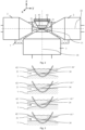
- Fig. 2 a section of the microscope 1 is shown in more detail. Thereby, it can be seen that centrally between the two illumination objectives 2 a sample holder 6 is positioned.
- the sample holder 6 tapers downwardly and has a rounded bottom.
- the tapering section and the rounded bottom form a transparent portion 62.
- the transparent portion 62 is transparent for the illumination light beams 21 propagated along the illumination path 22 and the detection light 31.
- the imaging objective 3 is arranged below sample holder 6 and the illumination objectives 2. Its orientation is perpendicular to the orientation of the illumination objectives 2.
- the imaging objective 3 and the illumination objectives 2 are placed in an immersion medium 7.
- the sample holder 6 is carried by a holder support (not visible in Fig. 2 ) which allows for moving the complete sample holder 6. It further has an interior which is open in an upward direction.
- the sample medium 61 containing the sample is arranged.
- the sample holder 6 is closed in a downward direction, i.e. in a direction of gravity, such that the sample medium 61 is held inside the sample holder 6 by means of the gravity.
- the sample medium 61 is illuminated by the illumination light beams 21 as shown in more detail in Fig. 3 .
- the sample medium 61 is illuminated in the imaging focal plane 34 of the imaging objective 3. Since in the top illustration the refractive indexes of the immersion medium 7, the transparent portion 62 of the sample holder 6 and the sample medium 61' are essentially the same the illumination light beams 21 can horizontally pass the sample holder 6 and the sample medium 61' even though it hits the sample holder 6 at a non-orthogonal or even sharp angle.
- the ARA 4 allows for moving the illumination light beams 21 along the detection axis 35 up and down, i.e. along a z-axis of a coordinate system shown in Fig. 2 .
- the imaging focal plane 34 can likewise be moved along the detection axis 35 independently from the illumination light beams 21.
- the illumination light beams 21 are deflected such that they do not horizontally pass the sample holder 6 in the imaging focal plane 34. This deteriorates the quality of the imaging.
- the deflection can be compensated by the following two correction mechanisms.
- the ARA 4 moves the illumination light beams 21 up and down along the detection axis 35, i.e. along the z-axis. Furthermore, as can be seen in the bottom illustration of Fig. 3 , the ARA 4 rotates the illumination light beams 21 in a rotational plane in which the detection axis 35 lies, thereby adjusting the angle between the illumination light beams 21 and the outer surface of the sample holder 6.
- the rotational plane is parallel to a y-axis and the z-axis of the coordinate system of Fig. 2 .
- the illumination light beams 21 can be manipulated such that they horizontally pass the sample holder 6 and the sample medium 61" in the imaging focal plane 34. Like this, the sample medium 61" can thoroughly be illuminated and imaged.
- This illustration of Fig. 3 shows illumination from one side only but, of course, equivalent applies for illumination from an opposite direction.
- the microscope 1 can be operated as follows: The sample medium 61 arranged inside the sample holder 6 is illuminated with the illumination light beam 21 ejected along the illumination path 22 through the transparent portion 62 of the sample holder 6 by the illumination objective 2.
- the imaging objective 3 receives the detection light 31 comprising at least a portion of the light ejected by the sample medium 61, wherein the detection light 31 is propagated along a detection path which lies orthogonal to the illumination path 22 and which defines the detection axis 35.
- the ARA 4 displaces the illumination light beam 21 relative to the imaging focal plane 34 along the detection axis 35 (z-axis).
- the ARA 4 also rotationally displaces the illumination light beam 21 in the rotational plane (y-z-plane) in which the detection axis 35 lies.
- the displacement of the illumination light beam 21 relative to the imaging focal plane 34 is changed based on a position of the sample medium 61 or on a position of a portion thereof in the sample holder 6.
- the sample medium 61 or the sample can be imaged by illuminating the sample medium 61 with the illumination light beam 21 ejected along the illumination path 22; the imaging objective 3 detecting light ejected from the sample medium 61 along the detection path 35 angled at 90° to the illumination path 22, wherein the detection light 31 comprises at least a portion of the light ejected from the sample medium 61; and displacing the illumination light beam 21 relative to the imaging focal plane 34 along the detection path 35.
- the displacement of the illumination light beam 21 relative to the imaging focal plane 34 is changed in accordance with changing positions of the sample medium 61.
- the illumination light beam 21 is brought in an alignment such that it intersects the imaging focal plane 34, wherein the sample medium 61 is imaged in a given position for a set of alignments of the illumination beam 21.
- an image of the sample medium 61 is taken for each of the set of alignments of the illumination beam; the images taken are evaluated to determine best alignment parameters based on contrast or other image quality features for the given position of the sample medium 61; the best alignment parameters are stored; and the illumination light beam 21 is displaced in compliance with the stored best alignment parameters.
- the disclosure also covers all further features shown in the Figs. individually although they may not have been described in the afore or following description. Also, single alternatives of the embodiments described in the figures and the description and single alternatives of features thereof can be disclaimed from the subject matter of the invention or from disclosed subject matter.
- the disclosure comprises subject matter consisting of the features defined in the claims or the exemplary embodiments as well as subject matter comprising said features.
Landscapes
- Physics & Mathematics (AREA)
- Chemical & Material Sciences (AREA)
- Analytical Chemistry (AREA)
- General Physics & Mathematics (AREA)
- Optics & Photonics (AREA)
- Engineering & Computer Science (AREA)
- Multimedia (AREA)
- Signal Processing (AREA)
- Oil, Petroleum & Natural Gas (AREA)
- Microscoopes, Condenser (AREA)
Claims (15)
- Mikroskop (1) zur Bildgebung einer Probe (61), umfassend:mindestens ein Beleuchtungsobjektiv (2), das so angeordnet ist, dass es einen Beleuchtungslichtstrahl (21) entlang eines Beleuchtungspfades (22) aussendet, um die Probe (61) zu beleuchten;ein Bildgebungsobjektiv (3), das so angeordnet ist, dass es Detektionslicht (31) empfängt, das mindestens einen Teil des von der Probe (61) ausgesendeten Lichts umfasst, wobei sich das Detektionslicht (31) entlang einer Detektionsachse (35) ausbreitet, die bevorzugt um etwa 90° zu dem Beleuchtungspfad (22) abgewinkelt ist, und wobei das Bildgebungsobjektiv (3) eine Bildgebungsbrennebene (34) aufweist;eine motorisierte und elektronisch gesteuerte Justieranordnung (4) zum linearen Verschieben des Beleuchtungslichtstrahls (21) und der Bildgebungsbrennebene (34) relativ zueinander entlang der Detektionsachse (35);einen Probenhalter (6), der so angeordnet ist, dass er eine Probe (61) aufnimmt, und der einen Abschnitt aufweist, der für den Beleuchtungslichtstrahl (21) und das Detektionslicht (31) durchlässig ist, wobei das Bildgebungsobjektiv (3) im Wesentlichen unter dem Probenhalter (6) positioniert ist; undeinen Halterträger, der so angeordnet ist, dass er den Probenhalter (6) aufnimmt und den Probenhalter (6) relativ zu dem Bildgebungsobjektiv (3) verschiebt, wobei der Halterträger ein Antriebssystem aufweist, das so angeordnet ist, dass es den Probenhalter (6) entlang dreier senkrechter Achsen verschiebt,wobei die Justieranordnung (4) so angeordnet ist, dass sie die Verschiebung des Beleuchtungslichtstrahls (21) und der Bildgebungsbrennebene (34) relativ zueinander entlang der Detektionsachse (35) in Synchronisation mit sich ändernden Positionen der Probe (61) entlang mindestens zwei der drei senkrechten Achsen ändert.
- Mikroskop (1) nach Anspruch 1, umfassendein weiteres Beleuchtungsobjektiv (2), das so angeordnet ist, dass es einen weiteren Beleuchtungslichtstrahl (21) entlang eines weiteren Beleuchtungspfades (22) aussendet, wobei das weitere Beleuchtungsobjektiv (2) bevorzugt im Wesentlichen identisch mit dem Beleuchtungsobjektiv (2) ist,eine weitere Justieranordnung (4) zum linearen Verschieben des weiteren Beleuchtungslichtstrahls (21) und der Bildgebungsbrennebene (34) relativ zueinander entlang der Detektionsachse (35), wobei die weitere Justieranordnung (4) bevorzugt im Wesentlichen mit der Justieranordnung (4) identisch ist,wobei das weitere Beleuchtungsobjektiv (2) so angeordnet ist, dass es den weiteren Beleuchtungslichtstrahl (21) im Wesentlichen entgegengesetzt zu dem Beleuchtungslichtstrahl (21) aussendet, undwobei die weitere Justieranordnung (4) bevorzugt so konfiguriert ist, dass sie den weiteren Beleuchtungslichtstrahl (21) und die Bildgebungsbrennebene (34) relativ zueinander entlang der Detektionsachse (35) unabhängig von der relativen Verschiebung zwischen dem Beleuchtungslichtstrahl (21) und der Bildgebungsbrennebene (34) entlang der Detektionsachse (35) linear verschiebt.
- Mikroskop (1) nach Anspruch 1 oder 2, wobei sich der durchlässige Abschnitt (62) des Probenhalters (6) entlang der Detektionsachse (35) verjüngt.
- Mikroskop (1) nach Anspruch 2 oder 3, wobei das Beleuchtungsobjektiv (2) und/oder das weitere Beleuchtungsobjektiv (2) und das Bildgebungsobjektiv (3) so konfiguriert sind, dass sie an jeweiligen festen Orten verbleiben, und wobei die Justieranordnung (4) und/oder die weitere Justieranordnung (4) räumlich von den Objektiven versetzt sind.
- Mikroskop (1) nach einem der vorstehenden Ansprüche, wobei sich die Justieranordnung (4) hinter dem Beleuchtungsobjektiv (2) befindet und eine Bewegung des Beleuchtungslichtstrahls (21) entlang der Detektionsachse (35) bestimmt.
- Mikroskop (1) nach einem der vorstehenden Ansprüche, wobei die Justieranordnung (4) mindestens einen Spiegel (41, 42) und bevorzugt zwei Spiegel (41, 42) umfasst, wobei die zwei Spiegel (41, 42) bevorzugt derart relativ zueinander beweglich angeordnet sind, dass eine Ausrichtung des Beleuchtungslichtstrahls (21) basierend auf einer Position des durchlässigen Abschnitts des aktuell abzubildenden Probenhalters (6) erreicht wird.
- Mikroskop (1) nach einem der vorstehenden Ansprüche, das eine Rotationsanordnung (4) zum rotatorischen Verschieben des Beleuchtungslichtstrahls (21) in einer durch die Detektionsachse (35) und den Beleuchtungspfad (22) definierten Rotationsebene umfasst.
- Mikroskop (1) nach Anspruch 7, wobei die Rotationsanordnung mindestens einen Spiegel (41, 42) und bevorzugt zwei Spiegel (41, 42) umfasst, wobei bevorzugt der mindestens einen Spiegel der Rotationsanordnung (4) dem mindestens einen Spiegel der Justieranordnung (4) entspricht, oder die zwei Spiegel der Rotationsanordnung (4) den zwei Spiegeln der Justieranordnung (4) entsprechen.
- Mikroskop (1) nach einem der vorstehenden Ansprüche, wobei das Beleuchtungsobjektiv (2) und das Bildgebungsobjektiv (3) in einem Immersionsmedium (7) platziert sind und bevorzugt der durchlässige Abschnitt des Probenhalters (6) aus einem Material besteht, das einen Brechungsindex aufweist, der einem Brechungsindex des Immersionsmediums (7) entspricht, wobeidas Immersionsmedium (7) bevorzugt Wasser oder eine Wasserlösung ist und der durchlässige Abschnitt des Probenhalters (6) eine Membran aus fluoriertem Ethylenpropylen ist, und/oderdie Probe ein Probenmedium (61, 61', 61") mit einem von dem Brechungsindex des Immersionsmediums (7) verschiedenen Brechungsindex aufweist, umfasst oder darin angeordnet ist.
- Mikroskop (1) nach einem der vorstehenden Ansprüche, wobei das Bildgebungsobjektiv (3) so positioniert ist, dass es im Wesentlichen gegen eine Richtung der Schwerkraft gerichtet ist, und das mindestens eine Beleuchtungsobjektiv (2) so positioniert ist, dass es im Wesentlichen senkrecht zu der Richtung der Schwerkraft gerichtet ist.
- Verfahren zur Bildgebung einer Probe (61), das die folgenden Schritte umfasst:- Beleuchten der Probe (61) mit einem Beleuchtungslichtstrahl (21), der entlang eines Beleuchtungspfades (22) ausgesendet wird;- ein Bildgebungsobjektiv (3), das eine Bildgebungsbrennebene (34) aufweist, das von der Probe (61) ausgesendetes Licht entlang eines Detektionspfades, der bevorzugt um etwa 90° zu dem Beleuchtungspfad (22) abgewinkelt ist, detektiert, wobei das Detektionslicht (31) mindestens einen Teil des von der Probe (61) ausgesendeten Lichts umfasst;- Verschieben des Beleuchtungslichtstrahls (21) und der Bildgebungsbrennebene (34) relativ zueinander entlang des Detektionsweges; und- Ändern der Verschiebung des Beleuchtungslichtstrahls (21) und der Bildgebungsbrennebene (34) relativ zueinander entlang der Detektionsachse (35) in Übereinstimmung mit sich ändernden Positionen der Probe (61) entlang mindestens zwei von drei senkrechten Achsen.
- Verfahren nach Anspruch 11, wobei
durch Verschieben des Beleuchtungslichtstrahls (21) und der Bildgebungsbrennebene (34) relativ zueinander entlang des Detektionspfades der Beleuchtungslichtstrahl (21) in eine Ausrichtung gebracht wird, so dass er die Bildgebungsbrennebene (34) schneidet, und die Probe (61) in einer gegebenen Position für einen Satz von Ausrichtungen des Beleuchtungsstrahls abgebildet wird. - Verfahren nach Anspruch 12, umfassend:- einen Schritt des Aufnehmens eines Bildes der Probe (61) für jede des Satzes von Ausrichtungen des Beleuchtungsstrahls;- einen Schritt des Auswertens der aufgenommenen Bilder, um die besten Ausrichtungsparameter für die gegebene Position der Probe (61) zu bestimmen;- einen Schritt des Speicherns der besten Ausrichtungsparameter; und- Verschieben des Beleuchtungslichtstrahls (21) in Übereinstimmung mit den gespeicherten besten Ausrichtungsparametern.
- Verfahren zum Betreiben eines Mikroskops (1) nach einem der Ansprüche 1 bis 10, das die folgenden Schritte umfasst:Anordnen einer Probe (61) innerhalb eines Probenhalters (6) des Mikroskops;ein Beleuchtungsobjektiv (2) des Mikroskops (1), das die Probe (61) mit einem Beleuchtungslichtstrahl (21) beleuchtet, der entlang eines Beleuchtungspfades durch einen durchlässigen Abschnitt des Probenhalters (6) ausgesendet wird;ein Bildgebungsobjektiv (3), das eine Bildgebungsbrennebene (34) aufweist, die Detektionslicht (31) empfängt, das mindestens einen Teil des von der Probe (61) ausgesendeten Lichts umfasst, wobei sich das Detektionslicht (31) entlang eines Detektionspfades ausbreitet, der im Wesentlichen orthogonal zu dem Beleuchtungspfad (22) verläuft und eine Detektionsachse (35) definiert; undVerschieben des Beleuchtungslichtstrahls (21) und der Bildgebungsbrennebene (34) relativ zueinander entlang der Detektionsachse (35).
- Verfahren nach Anspruch 14, umfassendÄndern der Verschiebung des Beleuchtungslichtstrahls (21) relativ zu der Bildgebungsbrennebene (34) entlang der Detektionsachse (35) basierend auf einer Position der Probe (61) oder einer Position eines Abschnitts davon in dem Probenhalter (6);Verschieben des Probenhalters (6) entlang mindestens zwei von drei senkrechten Achsen und/oder einen Schritt des Rotierens des Probenhalters (6) um mindestens eine Rotationsachse mit Hilfe eines Antriebssystems eines Halterträgers; und/oderrotatorisches Verschieben des Beleuchtungslichtstrahls (21) in einer Rotationsebene, in der die Detektionsachse (35) liegt,wobei sich der durchlässige Abschnitt des Probenhalters (6) bevorzugt entlang der Detektionsachse (35) verjüngt und der Beleuchtungslichtstrahl (21) so angeordnet ist, dass er in einem spitzen Winkel auf den Probenhalter (6) auftrifft.
Priority Applications (1)
| Application Number | Priority Date | Filing Date | Title |
|---|---|---|---|
| EP24221655.4A EP4502698A3 (de) | 2017-07-20 | 2018-07-20 | Mikroskop, verfahren zum betrieb eines mikroskops und verfahren zur abbildung einer probe |
Applications Claiming Priority (2)
| Application Number | Priority Date | Filing Date | Title |
|---|---|---|---|
| CH9462017 | 2017-07-20 | ||
| PCT/EP2018/069733 WO2019016359A1 (en) | 2017-07-20 | 2018-07-20 | MICROSCOPE, METHOD FOR OPERATING A MICROSCOPE, AND METHOD FOR IMAGING A SAMPLE |
Related Child Applications (1)
| Application Number | Title | Priority Date | Filing Date |
|---|---|---|---|
| EP24221655.4A Division EP4502698A3 (de) | 2017-07-20 | 2018-07-20 | Mikroskop, verfahren zum betrieb eines mikroskops und verfahren zur abbildung einer probe |
Publications (2)
| Publication Number | Publication Date |
|---|---|
| EP3655809A1 EP3655809A1 (de) | 2020-05-27 |
| EP3655809B1 true EP3655809B1 (de) | 2025-01-08 |
Family
ID=59745676
Family Applications (2)
| Application Number | Title | Priority Date | Filing Date |
|---|---|---|---|
| EP18749735.9A Active EP3655809B1 (de) | 2017-07-20 | 2018-07-20 | Mikroskop, verfahren zum betrieb eines mikroskops und verfahren zur bildgebung einer probe |
| EP24221655.4A Pending EP4502698A3 (de) | 2017-07-20 | 2018-07-20 | Mikroskop, verfahren zum betrieb eines mikroskops und verfahren zur abbildung einer probe |
Family Applications After (1)
| Application Number | Title | Priority Date | Filing Date |
|---|---|---|---|
| EP24221655.4A Pending EP4502698A3 (de) | 2017-07-20 | 2018-07-20 | Mikroskop, verfahren zum betrieb eines mikroskops und verfahren zur abbildung einer probe |
Country Status (4)
| Country | Link |
|---|---|
| US (2) | US11579428B2 (de) |
| EP (2) | EP3655809B1 (de) |
| CN (1) | CN111051954A (de) |
| WO (1) | WO2019016359A1 (de) |
Families Citing this family (8)
| Publication number | Priority date | Publication date | Assignee | Title |
|---|---|---|---|---|
| EP3707544A1 (de) * | 2017-11-10 | 2020-09-16 | Viventis Microscopy Sàrl | Mikroskop zur bildgebung einer probe und probenhalter für solch ein mikroskop |
| CN111504968A (zh) * | 2020-04-29 | 2020-08-07 | 锘海生物科学仪器(上海)股份有限公司 | 四色激光照明荧光显微镜 |
| DE102020128524A1 (de) * | 2020-10-29 | 2022-05-05 | Carl Zeiss Microscopy Gmbh | Lichtblattmikroskop und Verfahren der Lichtblattmikroskopie |
| CN117043655A (zh) * | 2021-01-22 | 2023-11-10 | 维微恩提斯显微镜有限责任公司 | 用于对样品进行成像的显微镜 |
| FR3119466B1 (fr) * | 2021-01-29 | 2023-02-10 | Damae Medical | Dispositifs pour l’analyse microscopique ex vivo d’échantillons et in vivo de la peau |
| EP4134724A1 (de) | 2021-08-13 | 2023-02-15 | European Molecular Biology Laboratory | Mikroskop mit invertiertem lichtblatt |
| US12574486B2 (en) | 2023-04-28 | 2026-03-10 | Beijing Boe Display Technology Co., Ltd. | Stereoscopic display device and control method thereof |
| EP4664180A1 (de) | 2024-06-12 | 2025-12-17 | Viventis Microscopy Sàrl | Verfahren zur erfassung von bildern und zugehöriges mikroskop |
Citations (4)
| Publication number | Priority date | Publication date | Assignee | Title |
|---|---|---|---|---|
| DE102007047461A1 (de) * | 2007-09-28 | 2009-04-02 | Carl Zeiss Microimaging Gmbh | Verfahren und optische Anordnung zur Untersuchung einer Probe |
| DE102007045897A1 (de) * | 2007-09-26 | 2009-04-09 | Carl Zeiss Microimaging Gmbh | Verfahren zur mikroskopischen dreidimensionalen Abbildung einer Probe |
| WO2014056992A1 (de) * | 2012-10-12 | 2014-04-17 | Carl Zeiss Microscopy Gmbh | Mikroskop und verfahren zur spim mikroskopie |
| WO2017075275A1 (en) * | 2015-10-29 | 2017-05-04 | The Board Of Trustees Of The Leland Stanford Junior University | Methods and systems for imaging a biological sample |
Family Cites Families (54)
| Publication number | Priority date | Publication date | Assignee | Title |
|---|---|---|---|---|
| JP2975476B2 (ja) | 1992-03-30 | 1999-11-10 | 三井金属鉱業株式会社 | 結晶内のフォトルミネッセンス計測方法及び装置 |
| JP3942785B2 (ja) * | 2000-01-26 | 2007-07-11 | エスアイアイ・ナノテクノロジー株式会社 | 光ファイバープローブおよび微小開口付カンチレバーと、それらの開口形成方法 |
| DE10257423A1 (de) | 2002-12-09 | 2004-06-24 | Europäisches Laboratorium für Molekularbiologie (EMBL) | Mikroskop |
| US20110259744A1 (en) * | 2003-04-30 | 2011-10-27 | Moyle William R | Sensors for biomolecular detection and cell classification |
| JP2006091723A (ja) | 2004-09-27 | 2006-04-06 | Olympus Corp | 倒立顕微鏡 |
| US8254020B2 (en) | 2006-04-20 | 2012-08-28 | Washington University | Objective-coupled selective plane illumination microscopy |
| US20090203536A1 (en) * | 2006-06-06 | 2009-08-13 | Vermette Patrick | Assay supports comprising a peg support, said support attached from a peg solution in cloud point (theta solvent) conditions |
| DE102007015061A1 (de) * | 2007-03-29 | 2008-10-02 | Carl Zeiss Microimaging Gmbh | Probenhalterung für ein Mikroskop |
| DE102007047464B4 (de) | 2007-09-28 | 2023-03-02 | Carl Zeiss Microscopy Gmbh | Optische Anordnung zur Photomanipulation |
| EP2206021B1 (de) * | 2007-10-30 | 2015-01-28 | New York University | Verfolgung und kennzeichnung von partikeln über holographische videomikroskopie |
| EP2284519B1 (de) * | 2008-05-15 | 2015-12-09 | Shimadzu Corporation | Biologische bildgebungsvorrichtung |
| WO2010014244A2 (en) | 2008-07-30 | 2010-02-04 | The Regents Of The University Of California, San Francisco | Multidirectional selective plane illumination microscopy |
| DE102009044984A1 (de) * | 2009-09-24 | 2011-03-31 | Carl Zeiss Microimaging Gmbh | Mikroskop |
| DE102009044986A1 (de) | 2009-09-24 | 2011-03-31 | Carl Zeiss Microimaging Gmbh | Mikroskop |
| DE102012214568A1 (de) | 2012-08-16 | 2014-02-20 | Leica Microsystems Cms Gmbh | Optische Anordnung und ein Mikroskop |
| US9404869B2 (en) | 2012-10-09 | 2016-08-02 | Howard Hughes Medical Institute | Multiview light-sheet microscopy |
| JP6086366B2 (ja) | 2013-04-05 | 2017-03-01 | 国立研究開発法人理化学研究所 | 顕微鏡、焦準器具、流体保持器具、及び光学ユニット |
| EP3605183A1 (de) | 2013-05-10 | 2020-02-05 | European Molecular Biology Laboratory | Mikroskop für die spim mikroskopie |
| DE202013012338U1 (de) | 2013-07-10 | 2016-06-09 | Carl Zeiss Microscopy Gmbh | Anordnung zur Lichtblattmikroskopie |
| US9581798B2 (en) | 2013-07-22 | 2017-02-28 | Fundacio Institut De Ciencies Fotoniques | Light sheet-based imaging device with extended depth of field |
| DE102013110093B3 (de) | 2013-09-13 | 2015-01-22 | Johann Wolfgang Goethe-Universität | Küvette für eine inverse Fluoreszenz-Untersuchung |
| GB2520541A (en) | 2013-11-25 | 2015-05-27 | European Molecular Biology Lab Embl | Optical arrangement for imaging a sample |
| WO2015108846A1 (en) | 2014-01-14 | 2015-07-23 | Applied Scientific Instrumentation, Inc. | Light sheet generator |
| EP3102966A4 (de) * | 2014-02-03 | 2017-10-11 | The Arizona Board of Regents On Behalf of the University of Arizona | Beta- und alpha-emissionstomografie für dreidimensionale autoradiographie |
| NL2012218C2 (en) * | 2014-02-06 | 2015-08-10 | Univ Delft Tech | Method and apparatus for determining a density of fluorescent markers in a sample. |
| EP2916158A1 (de) * | 2014-03-06 | 2015-09-09 | European Molecular Biology Laboratory | Mikroskop |
| DE102014104977B4 (de) | 2014-04-08 | 2023-11-30 | Carl Zeiss Microscopy Gmbh | Anordnung zur Lichtblattmikroskopie sowie Mikroskopobjektiv für die Lichtblattmikroskopie |
| GB201409202D0 (en) * | 2014-05-23 | 2014-07-09 | Ffei Ltd | Improvements in imaging microscope samples |
| CN104155274B (zh) | 2014-08-07 | 2016-11-23 | 华中科技大学 | 一种双光束光片照明显微扫描成像方法及显微镜 |
| JP6522361B2 (ja) | 2015-02-18 | 2019-05-29 | オリンパス株式会社 | 蛍光顕微鏡 |
| US10989661B2 (en) | 2015-05-01 | 2021-04-27 | The Board Of Regents Of The University Of Texas System | Uniform and scalable light-sheets generated by extended focusing |
| GB201508376D0 (en) * | 2015-05-15 | 2015-07-01 | Univ St Andrews | Light sheet imaging |
| DE102015209756A1 (de) | 2015-05-28 | 2016-12-01 | Carl Zeiss Microscopy Gmbh | Anordnung und Verfahren zur Lichtblattmikroskopie |
| DE102015110795A1 (de) * | 2015-07-03 | 2017-01-05 | Carl Zeiss Microscopy Gmbh | Optikvorrichtung mit einem Optikmodul, das mindestens ein optisches Element aufweist |
| DE102015116452A1 (de) * | 2015-09-29 | 2017-03-30 | Carl Zeiss Microscopy Gmbh | Mikroskop |
| JP2018004777A (ja) | 2016-06-28 | 2018-01-11 | オリンパス株式会社 | 光シート顕微鏡、及び、光シート顕微鏡の制御方法 |
| CN106053346B (zh) | 2016-06-29 | 2018-06-08 | 华中科技大学 | 一种光片显微成像转换装置 |
| JP2018017970A (ja) | 2016-07-29 | 2018-02-01 | オリンパス株式会社 | 光シート顕微鏡、及び、光シート顕微鏡の制御方法 |
| JP6685202B2 (ja) | 2016-08-19 | 2020-04-22 | オリンパス株式会社 | シート照明装置 |
| DE102016120683A1 (de) | 2016-10-28 | 2018-05-03 | Carl Zeiss Microscopy Gmbh | Lichtblattmikroskop |
| WO2018148309A1 (en) | 2017-02-08 | 2018-08-16 | The Regents Of The University Of California | Selective plane illumination in the conventional inverted microscope geometry by side illumination |
| JP2018169502A (ja) | 2017-03-30 | 2018-11-01 | オリンパス株式会社 | 顕微鏡装置 |
| EP3396430B1 (de) * | 2017-04-27 | 2023-08-16 | Euroimmun Medizinische Labordiagnostika AG | Optische abtastanordnung und verfahren |
| DE102017119480A1 (de) | 2017-08-25 | 2019-02-28 | Carl Zeiss Microscopy Gmbh | Optische Anordnung zum Scannen von Anregungsstrahlung und/oder Manipulationsstrahlung in einem Laser-Scanning-Mikroskop und Laser-Scanning-Mikroskop |
| DE102017119478A1 (de) | 2017-08-25 | 2019-02-28 | Carl Zeiss Microscopy Gmbh | Optische Anordnung zum Scannen von Anregungsstrahlung und/oder Manipulationsstrahlung in einem Laser-Scanning-Mikroskop und Laser-Scanning-Mikroskop |
| US11709351B2 (en) * | 2017-11-13 | 2023-07-25 | The Trustees Of The University Of Pennsylvania | Light-sheet fluorescence imaging with elliptical light shaping diffuser |
| WO2019129646A1 (en) * | 2017-12-29 | 2019-07-04 | F. Hoffmann-La Roche Ag | Tissue sample preparation system |
| JP2021512299A (ja) * | 2018-01-25 | 2021-05-13 | エッセンリックス コーポレーション | 試料中の細胞および非細胞分析物の並行アッセイ法 |
| WO2019148008A1 (en) * | 2018-01-26 | 2019-08-01 | University Of Washington | Apparatuses and methods for multi-direction digital scanned light sheet microscopy |
| JP7085364B2 (ja) | 2018-02-28 | 2022-06-16 | 浜松ホトニクス株式会社 | ライトシート顕微鏡及び試料観察方法 |
| CN109596588B (zh) | 2018-12-16 | 2021-10-08 | 华中科技大学 | 一种基于光片照明的高分辨率四维光场显微成像系统 |
| WO2021183945A1 (en) | 2020-03-13 | 2021-09-16 | University Of Southern California | Optimized photon collection for light-sheet microscopy |
| EP4134724A1 (de) | 2021-08-13 | 2023-02-15 | European Molecular Biology Laboratory | Mikroskop mit invertiertem lichtblatt |
| DE102022200841B3 (de) | 2022-01-26 | 2023-05-04 | Carl Zeiss Microscopy Gmbh | Verfahren, Anordnung und Mikroskop zur dreidimensionalen Bildgebung in der Mikroskopie unter Nutzung einer asymmetrischen Punktbildübertragungsfunktion |
-
2018
- 2018-07-20 EP EP18749735.9A patent/EP3655809B1/de active Active
- 2018-07-20 CN CN201880053318.2A patent/CN111051954A/zh active Pending
- 2018-07-20 EP EP24221655.4A patent/EP4502698A3/de active Pending
- 2018-07-20 US US16/632,074 patent/US11579428B2/en active Active
- 2018-07-20 WO PCT/EP2018/069733 patent/WO2019016359A1/en not_active Ceased
-
2023
- 2023-01-10 US US18/152,572 patent/US12147021B2/en active Active
Patent Citations (4)
| Publication number | Priority date | Publication date | Assignee | Title |
|---|---|---|---|---|
| DE102007045897A1 (de) * | 2007-09-26 | 2009-04-09 | Carl Zeiss Microimaging Gmbh | Verfahren zur mikroskopischen dreidimensionalen Abbildung einer Probe |
| DE102007047461A1 (de) * | 2007-09-28 | 2009-04-02 | Carl Zeiss Microimaging Gmbh | Verfahren und optische Anordnung zur Untersuchung einer Probe |
| WO2014056992A1 (de) * | 2012-10-12 | 2014-04-17 | Carl Zeiss Microscopy Gmbh | Mikroskop und verfahren zur spim mikroskopie |
| WO2017075275A1 (en) * | 2015-10-29 | 2017-05-04 | The Board Of Trustees Of The Leland Stanford Junior University | Methods and systems for imaging a biological sample |
Also Published As
| Publication number | Publication date |
|---|---|
| US11579428B2 (en) | 2023-02-14 |
| EP4502698A3 (de) | 2025-04-30 |
| EP3655809A1 (de) | 2020-05-27 |
| US12147021B2 (en) | 2024-11-19 |
| WO2019016359A1 (en) | 2019-01-24 |
| US20230161142A1 (en) | 2023-05-25 |
| CN111051954A (zh) | 2020-04-21 |
| EP4502698A2 (de) | 2025-02-05 |
| US20200233194A1 (en) | 2020-07-23 |
Similar Documents
| Publication | Publication Date | Title |
|---|---|---|
| US12147021B2 (en) | Microscope, method of operating a microscope and method of imaging a sample | |
| US10712547B2 (en) | Microscope, focusing unit, fluid holding unit, and optical unit | |
| JP6195922B2 (ja) | 顕微鏡 | |
| JP6514198B2 (ja) | 光シート顕微鏡検査用の装置 | |
| EP1857853B1 (de) | Beleuchtungsvorrichtung | |
| US10048478B2 (en) | Optical transmission system for correcting image errors and microscope with such a transmission system | |
| US20180314047A1 (en) | Microscope | |
| US20140147884A1 (en) | Laser microdissection device and method | |
| US20200278525A1 (en) | Microscope for imaging a sample and sample holder for such a microscope | |
| EP3074807B1 (de) | Optische anordnung zur abbildung einer probe | |
| CN113396350A (zh) | 使用投影参照物来引导校正光学器件的调节的成像系统和方法 | |
| JP6832735B2 (ja) | 顕微鏡 | |
| US20260023252A1 (en) | Microscope for imaging a sample | |
| JP2021515910A (ja) | 大型試料を走査するための光学装置、光学モジュールおよび顕微鏡 | |
| JP4700334B2 (ja) | 全反射蛍光顕微鏡 | |
| JP2008267842A (ja) | 生物観察容器並びにこれを用いる生物顕微鏡及び生物観察装置 | |
| CN110520778A (zh) | 光片显微镜 | |
| JP2009181123A (ja) | 走査型レーザ顕微鏡および非デスキャン検出のためのサブアセンブリ | |
| JP2012003284A (ja) | 全反射型顕微鏡 | |
| US11333872B2 (en) | Rotary objective lens switching device for a planar laser beam microscope | |
| HK1228014B (en) | Optical arrangement for imaging a sample |
Legal Events
| Date | Code | Title | Description |
|---|---|---|---|
| STAA | Information on the status of an ep patent application or granted ep patent |
Free format text: STATUS: UNKNOWN |
|
| STAA | Information on the status of an ep patent application or granted ep patent |
Free format text: STATUS: THE INTERNATIONAL PUBLICATION HAS BEEN MADE |
|
| PUAI | Public reference made under article 153(3) epc to a published international application that has entered the european phase |
Free format text: ORIGINAL CODE: 0009012 |
|
| STAA | Information on the status of an ep patent application or granted ep patent |
Free format text: STATUS: REQUEST FOR EXAMINATION WAS MADE |
|
| 17P | Request for examination filed |
Effective date: 20200219 |
|
| AK | Designated contracting states |
Kind code of ref document: A1 Designated state(s): AL AT BE BG CH CY CZ DE DK EE ES FI FR GB GR HR HU IE IS IT LI LT LU LV MC MK MT NL NO PL PT RO RS SE SI SK SM TR |
|
| AX | Request for extension of the european patent |
Extension state: BA ME |
|
| DAV | Request for validation of the european patent (deleted) | ||
| DAX | Request for extension of the european patent (deleted) | ||
| STAA | Information on the status of an ep patent application or granted ep patent |
Free format text: STATUS: EXAMINATION IS IN PROGRESS |
|
| 17Q | First examination report despatched |
Effective date: 20220714 |
|
| GRAP | Despatch of communication of intention to grant a patent |
Free format text: ORIGINAL CODE: EPIDOSNIGR1 |
|
| STAA | Information on the status of an ep patent application or granted ep patent |
Free format text: STATUS: GRANT OF PATENT IS INTENDED |
|
| INTG | Intention to grant announced |
Effective date: 20240819 |
|
| GRAS | Grant fee paid |
Free format text: ORIGINAL CODE: EPIDOSNIGR3 |
|
| GRAA | (expected) grant |
Free format text: ORIGINAL CODE: 0009210 |
|
| STAA | Information on the status of an ep patent application or granted ep patent |
Free format text: STATUS: THE PATENT HAS BEEN GRANTED |
|
| P01 | Opt-out of the competence of the unified patent court (upc) registered |
Free format text: CASE NUMBER: APP_59839/2024 Effective date: 20241105 |
|
| AK | Designated contracting states |
Kind code of ref document: B1 Designated state(s): AL AT BE BG CH CY CZ DE DK EE ES FI FR GB GR HR HU IE IS IT LI LT LU LV MC MK MT NL NO PL PT RO RS SE SI SK SM TR |
|
| REG | Reference to a national code |
Ref country code: GB Ref legal event code: FG4D |
|
| REG | Reference to a national code |
Ref country code: CH Ref legal event code: EP |
|
| REG | Reference to a national code |
Ref country code: DE Ref legal event code: R096 Ref document number: 602018078348 Country of ref document: DE |
|
| REG | Reference to a national code |
Ref country code: IE Ref legal event code: FG4D |
|
| REG | Reference to a national code |
Ref country code: LT Ref legal event code: MG9D |
|
| REG | Reference to a national code |
Ref country code: NL Ref legal event code: MP Effective date: 20250108 |
|
| REG | Reference to a national code |
Ref country code: AT Ref legal event code: MK05 Ref document number: 1758696 Country of ref document: AT Kind code of ref document: T Effective date: 20250108 |
|
| PG25 | Lapsed in a contracting state [announced via postgrant information from national office to epo] |
Ref country code: NL Free format text: LAPSE BECAUSE OF FAILURE TO SUBMIT A TRANSLATION OF THE DESCRIPTION OR TO PAY THE FEE WITHIN THE PRESCRIBED TIME-LIMIT Effective date: 20250108 |
|
| PG25 | Lapsed in a contracting state [announced via postgrant information from national office to epo] |
Ref country code: RS Free format text: LAPSE BECAUSE OF FAILURE TO SUBMIT A TRANSLATION OF THE DESCRIPTION OR TO PAY THE FEE WITHIN THE PRESCRIBED TIME-LIMIT Effective date: 20250408 |
|
| PG25 | Lapsed in a contracting state [announced via postgrant information from national office to epo] |
Ref country code: FI Free format text: LAPSE BECAUSE OF FAILURE TO SUBMIT A TRANSLATION OF THE DESCRIPTION OR TO PAY THE FEE WITHIN THE PRESCRIBED TIME-LIMIT Effective date: 20250108 |
|
| PG25 | Lapsed in a contracting state [announced via postgrant information from national office to epo] |
Ref country code: PL Free format text: LAPSE BECAUSE OF FAILURE TO SUBMIT A TRANSLATION OF THE DESCRIPTION OR TO PAY THE FEE WITHIN THE PRESCRIBED TIME-LIMIT Effective date: 20250108 |
|
| PG25 | Lapsed in a contracting state [announced via postgrant information from national office to epo] |
Ref country code: ES Free format text: LAPSE BECAUSE OF FAILURE TO SUBMIT A TRANSLATION OF THE DESCRIPTION OR TO PAY THE FEE WITHIN THE PRESCRIBED TIME-LIMIT Effective date: 20250108 |
|
| PG25 | Lapsed in a contracting state [announced via postgrant information from national office to epo] |
Ref country code: NO Free format text: LAPSE BECAUSE OF FAILURE TO SUBMIT A TRANSLATION OF THE DESCRIPTION OR TO PAY THE FEE WITHIN THE PRESCRIBED TIME-LIMIT Effective date: 20250408 Ref country code: IS Free format text: LAPSE BECAUSE OF FAILURE TO SUBMIT A TRANSLATION OF THE DESCRIPTION OR TO PAY THE FEE WITHIN THE PRESCRIBED TIME-LIMIT Effective date: 20250508 |
|
| PG25 | Lapsed in a contracting state [announced via postgrant information from national office to epo] |
Ref country code: HR Free format text: LAPSE BECAUSE OF FAILURE TO SUBMIT A TRANSLATION OF THE DESCRIPTION OR TO PAY THE FEE WITHIN THE PRESCRIBED TIME-LIMIT Effective date: 20250108 |
|
| PG25 | Lapsed in a contracting state [announced via postgrant information from national office to epo] |
Ref country code: LV Free format text: LAPSE BECAUSE OF FAILURE TO SUBMIT A TRANSLATION OF THE DESCRIPTION OR TO PAY THE FEE WITHIN THE PRESCRIBED TIME-LIMIT Effective date: 20250108 Ref country code: PT Free format text: LAPSE BECAUSE OF FAILURE TO SUBMIT A TRANSLATION OF THE DESCRIPTION OR TO PAY THE FEE WITHIN THE PRESCRIBED TIME-LIMIT Effective date: 20250508 |
|
| PG25 | Lapsed in a contracting state [announced via postgrant information from national office to epo] |
Ref country code: BG Free format text: LAPSE BECAUSE OF FAILURE TO SUBMIT A TRANSLATION OF THE DESCRIPTION OR TO PAY THE FEE WITHIN THE PRESCRIBED TIME-LIMIT Effective date: 20250108 Ref country code: GR Free format text: LAPSE BECAUSE OF FAILURE TO SUBMIT A TRANSLATION OF THE DESCRIPTION OR TO PAY THE FEE WITHIN THE PRESCRIBED TIME-LIMIT Effective date: 20250409 |
|
| PG25 | Lapsed in a contracting state [announced via postgrant information from national office to epo] |
Ref country code: AT Free format text: LAPSE BECAUSE OF FAILURE TO SUBMIT A TRANSLATION OF THE DESCRIPTION OR TO PAY THE FEE WITHIN THE PRESCRIBED TIME-LIMIT Effective date: 20250108 |
|
| PG25 | Lapsed in a contracting state [announced via postgrant information from national office to epo] |
Ref country code: SE Free format text: LAPSE BECAUSE OF FAILURE TO SUBMIT A TRANSLATION OF THE DESCRIPTION OR TO PAY THE FEE WITHIN THE PRESCRIBED TIME-LIMIT Effective date: 20250108 |
|
| PG25 | Lapsed in a contracting state [announced via postgrant information from national office to epo] |
Ref country code: SM Free format text: LAPSE BECAUSE OF FAILURE TO SUBMIT A TRANSLATION OF THE DESCRIPTION OR TO PAY THE FEE WITHIN THE PRESCRIBED TIME-LIMIT Effective date: 20250108 |
|
| REG | Reference to a national code |
Ref country code: DE Ref legal event code: R097 Ref document number: 602018078348 Country of ref document: DE |
|
| PG25 | Lapsed in a contracting state [announced via postgrant information from national office to epo] |
Ref country code: DK Free format text: LAPSE BECAUSE OF FAILURE TO SUBMIT A TRANSLATION OF THE DESCRIPTION OR TO PAY THE FEE WITHIN THE PRESCRIBED TIME-LIMIT Effective date: 20250108 |
|
| PGFP | Annual fee paid to national office [announced via postgrant information from national office to epo] |
Ref country code: DE Payment date: 20250728 Year of fee payment: 8 |
|
| PGFP | Annual fee paid to national office [announced via postgrant information from national office to epo] |
Ref country code: GB Payment date: 20250722 Year of fee payment: 8 |
|
| PGFP | Annual fee paid to national office [announced via postgrant information from national office to epo] |
Ref country code: FR Payment date: 20250725 Year of fee payment: 8 |
|
| PGFP | Annual fee paid to national office [announced via postgrant information from national office to epo] |
Ref country code: CH Payment date: 20250924 Year of fee payment: 8 |
|
| PG25 | Lapsed in a contracting state [announced via postgrant information from national office to epo] |
Ref country code: CZ Free format text: LAPSE BECAUSE OF FAILURE TO SUBMIT A TRANSLATION OF THE DESCRIPTION OR TO PAY THE FEE WITHIN THE PRESCRIBED TIME-LIMIT Effective date: 20250108 Ref country code: EE Free format text: LAPSE BECAUSE OF FAILURE TO SUBMIT A TRANSLATION OF THE DESCRIPTION OR TO PAY THE FEE WITHIN THE PRESCRIBED TIME-LIMIT Effective date: 20250108 |
|
| PG25 | Lapsed in a contracting state [announced via postgrant information from national office to epo] |
Ref country code: RO Free format text: LAPSE BECAUSE OF FAILURE TO SUBMIT A TRANSLATION OF THE DESCRIPTION OR TO PAY THE FEE WITHIN THE PRESCRIBED TIME-LIMIT Effective date: 20250108 |
|
| PG25 | Lapsed in a contracting state [announced via postgrant information from national office to epo] |
Ref country code: SK Free format text: LAPSE BECAUSE OF FAILURE TO SUBMIT A TRANSLATION OF THE DESCRIPTION OR TO PAY THE FEE WITHIN THE PRESCRIBED TIME-LIMIT Effective date: 20250108 |
|
| PLBE | No opposition filed within time limit |
Free format text: ORIGINAL CODE: 0009261 |
|
| STAA | Information on the status of an ep patent application or granted ep patent |
Free format text: STATUS: NO OPPOSITION FILED WITHIN TIME LIMIT |
|
| REG | Reference to a national code |
Ref country code: CH Ref legal event code: L10 Free format text: ST27 STATUS EVENT CODE: U-0-0-L10-L00 (AS PROVIDED BY THE NATIONAL OFFICE) Effective date: 20251119 |
|
| 26N | No opposition filed |
Effective date: 20251009 |
|
| PG25 | Lapsed in a contracting state [announced via postgrant information from national office to epo] |
Ref country code: IT Free format text: LAPSE BECAUSE OF FAILURE TO SUBMIT A TRANSLATION OF THE DESCRIPTION OR TO PAY THE FEE WITHIN THE PRESCRIBED TIME-LIMIT Effective date: 20250108 |
|
| PG25 | Lapsed in a contracting state [announced via postgrant information from national office to epo] |
Ref country code: LU Free format text: LAPSE BECAUSE OF NON-PAYMENT OF DUE FEES Effective date: 20250720 |
|
| REG | Reference to a national code |
Ref country code: BE Ref legal event code: MM Effective date: 20250731 |
|
| PG25 | Lapsed in a contracting state [announced via postgrant information from national office to epo] |
Ref country code: BE Free format text: LAPSE BECAUSE OF NON-PAYMENT OF DUE FEES Effective date: 20250731 |
|
| PG25 | Lapsed in a contracting state [announced via postgrant information from national office to epo] |
Ref country code: LT Free format text: LAPSE BECAUSE OF FAILURE TO SUBMIT A TRANSLATION OF THE DESCRIPTION OR TO PAY THE FEE WITHIN THE PRESCRIBED TIME-LIMIT Effective date: 20250108 |
|
| PG25 | Lapsed in a contracting state [announced via postgrant information from national office to epo] |
Ref country code: IE Free format text: LAPSE BECAUSE OF NON-PAYMENT OF DUE FEES Effective date: 20250720 |
|
| PG25 | Lapsed in a contracting state [announced via postgrant information from national office to epo] |
Ref country code: MC Free format text: LAPSE BECAUSE OF FAILURE TO SUBMIT A TRANSLATION OF THE DESCRIPTION OR TO PAY THE FEE WITHIN THE PRESCRIBED TIME-LIMIT Effective date: 20250108 |
|
| REG | Reference to a national code |
Ref country code: CH Ref legal event code: U11 Free format text: ST27 STATUS EVENT CODE: U-0-0-U10-U11 (AS PROVIDED BY THE NATIONAL OFFICE) Effective date: 20260801 |
|
| PG25 | Lapsed in a contracting state [announced via postgrant information from national office to epo] |
Ref country code: CY Free format text: LAPSE BECAUSE OF FAILURE TO SUBMIT A TRANSLATION OF THE DESCRIPTION OR TO PAY THE FEE WITHIN THE PRESCRIBED TIME-LIMIT Effective date: 20250108 |