EP3655811B1 - Procédés et systèmes de commande de transmission de lumière non linéaire - Google Patents
Procédés et systèmes de commande de transmission de lumière non linéaire Download PDFInfo
- Publication number
- EP3655811B1 EP3655811B1 EP18836204.0A EP18836204A EP3655811B1 EP 3655811 B1 EP3655811 B1 EP 3655811B1 EP 18836204 A EP18836204 A EP 18836204A EP 3655811 B1 EP3655811 B1 EP 3655811B1
- Authority
- EP
- European Patent Office
- Prior art keywords
- light
- fiber
- phase
- nonlinear
- spatial
- Prior art date
- Legal status (The legal status is an assumption and is not a legal conclusion. Google has not performed a legal analysis and makes no representation as to the accuracy of the status listed.)
- Active
Links
Images







Classifications
-
- G—PHYSICS
- G02—OPTICS
- G02F—OPTICAL DEVICES OR ARRANGEMENTS FOR THE CONTROL OF LIGHT BY MODIFICATION OF THE OPTICAL PROPERTIES OF THE MEDIA OF THE ELEMENTS INVOLVED THEREIN; NON-LINEAR OPTICS; FREQUENCY-CHANGING OF LIGHT; OPTICAL LOGIC ELEMENTS; OPTICAL ANALOGUE/DIGITAL CONVERTERS
- G02F1/00—Devices or arrangements for the control of the intensity, colour, phase, polarisation or direction of light arriving from an independent light source, e.g. switching, gating or modulating; Non-linear optics
- G02F1/35—Non-linear optics
- G02F1/365—Non-linear optics in an optical waveguide structure
-
- G—PHYSICS
- G01—MEASURING; TESTING
- G01N—INVESTIGATING OR ANALYSING MATERIALS BY DETERMINING THEIR CHEMICAL OR PHYSICAL PROPERTIES
- G01N21/00—Investigating or analysing materials by the use of optical means, i.e. using sub-millimetre waves, infrared, visible or ultraviolet light
- G01N21/62—Systems in which the material investigated is excited whereby it emits light or causes a change in wavelength of the incident light
- G01N21/63—Systems in which the material investigated is excited whereby it emits light or causes a change in wavelength of the incident light optically excited
- G01N21/65—Raman scattering
-
- G—PHYSICS
- G01—MEASURING; TESTING
- G01N—INVESTIGATING OR ANALYSING MATERIALS BY DETERMINING THEIR CHEMICAL OR PHYSICAL PROPERTIES
- G01N29/00—Investigating or analysing materials by the use of ultrasonic, sonic or infrasonic waves; Visualisation of the interior of objects by transmitting ultrasonic or sonic waves through the object
- G01N29/44—Processing the detected response signal, e.g. electronic circuits specially adapted therefor
- G01N29/46—Processing the detected response signal, e.g. electronic circuits specially adapted therefor by spectral analysis, e.g. Fourier analysis or wavelet analysis
-
- G—PHYSICS
- G02—OPTICS
- G02F—OPTICAL DEVICES OR ARRANGEMENTS FOR THE CONTROL OF LIGHT BY MODIFICATION OF THE OPTICAL PROPERTIES OF THE MEDIA OF THE ELEMENTS INVOLVED THEREIN; NON-LINEAR OPTICS; FREQUENCY-CHANGING OF LIGHT; OPTICAL LOGIC ELEMENTS; OPTICAL ANALOGUE/DIGITAL CONVERTERS
- G02F1/00—Devices or arrangements for the control of the intensity, colour, phase, polarisation or direction of light arriving from an independent light source, e.g. switching, gating or modulating; Non-linear optics
- G02F1/35—Non-linear optics
- G02F1/3501—Constructional details or arrangements of non-linear optical devices, e.g. shape of non-linear crystals
-
- G—PHYSICS
- G02—OPTICS
- G02F—OPTICAL DEVICES OR ARRANGEMENTS FOR THE CONTROL OF LIGHT BY MODIFICATION OF THE OPTICAL PROPERTIES OF THE MEDIA OF THE ELEMENTS INVOLVED THEREIN; NON-LINEAR OPTICS; FREQUENCY-CHANGING OF LIGHT; OPTICAL LOGIC ELEMENTS; OPTICAL ANALOGUE/DIGITAL CONVERTERS
- G02F1/00—Devices or arrangements for the control of the intensity, colour, phase, polarisation or direction of light arriving from an independent light source, e.g. switching, gating or modulating; Non-linear optics
- G02F1/35—Non-linear optics
- G02F1/353—Frequency conversion, i.e. wherein a light beam is generated with frequency components different from those of the incident light beams
- G02F1/3536—Four-wave interaction
-
- G—PHYSICS
- G02—OPTICS
- G02F—OPTICAL DEVICES OR ARRANGEMENTS FOR THE CONTROL OF LIGHT BY MODIFICATION OF THE OPTICAL PROPERTIES OF THE MEDIA OF THE ELEMENTS INVOLVED THEREIN; NON-LINEAR OPTICS; FREQUENCY-CHANGING OF LIGHT; OPTICAL LOGIC ELEMENTS; OPTICAL ANALOGUE/DIGITAL CONVERTERS
- G02F2201/00—Constructional arrangements not provided for in groups G02F1/00 - G02F7/00
- G02F2201/02—Constructional arrangements not provided for in groups G02F1/00 - G02F7/00 fibre
-
- G—PHYSICS
- G02—OPTICS
- G02F—OPTICAL DEVICES OR ARRANGEMENTS FOR THE CONTROL OF LIGHT BY MODIFICATION OF THE OPTICAL PROPERTIES OF THE MEDIA OF THE ELEMENTS INVOLVED THEREIN; NON-LINEAR OPTICS; FREQUENCY-CHANGING OF LIGHT; OPTICAL LOGIC ELEMENTS; OPTICAL ANALOGUE/DIGITAL CONVERTERS
- G02F2201/00—Constructional arrangements not provided for in groups G02F1/00 - G02F7/00
- G02F2201/05—Constructional arrangements not provided for in groups G02F1/00 - G02F7/00 multimode
-
- G—PHYSICS
- G02—OPTICS
- G02F—OPTICAL DEVICES OR ARRANGEMENTS FOR THE CONTROL OF LIGHT BY MODIFICATION OF THE OPTICAL PROPERTIES OF THE MEDIA OF THE ELEMENTS INVOLVED THEREIN; NON-LINEAR OPTICS; FREQUENCY-CHANGING OF LIGHT; OPTICAL LOGIC ELEMENTS; OPTICAL ANALOGUE/DIGITAL CONVERTERS
- G02F2201/00—Constructional arrangements not provided for in groups G02F1/00 - G02F7/00
- G02F2201/58—Arrangements comprising a monitoring photodetector
-
- G—PHYSICS
- G02—OPTICS
- G02F—OPTICAL DEVICES OR ARRANGEMENTS FOR THE CONTROL OF LIGHT BY MODIFICATION OF THE OPTICAL PROPERTIES OF THE MEDIA OF THE ELEMENTS INVOLVED THEREIN; NON-LINEAR OPTICS; FREQUENCY-CHANGING OF LIGHT; OPTICAL LOGIC ELEMENTS; OPTICAL ANALOGUE/DIGITAL CONVERTERS
- G02F2203/00—Function characteristic
- G02F2203/12—Function characteristic spatial light modulator
-
- G—PHYSICS
- G02—OPTICS
- G02F—OPTICAL DEVICES OR ARRANGEMENTS FOR THE CONTROL OF LIGHT BY MODIFICATION OF THE OPTICAL PROPERTIES OF THE MEDIA OF THE ELEMENTS INVOLVED THEREIN; NON-LINEAR OPTICS; FREQUENCY-CHANGING OF LIGHT; OPTICAL LOGIC ELEMENTS; OPTICAL ANALOGUE/DIGITAL CONVERTERS
- G02F2203/00—Function characteristic
- G02F2203/18—Function characteristic adaptive optics, e.g. wavefront correction
-
- G—PHYSICS
- G02—OPTICS
- G02F—OPTICAL DEVICES OR ARRANGEMENTS FOR THE CONTROL OF LIGHT BY MODIFICATION OF THE OPTICAL PROPERTIES OF THE MEDIA OF THE ELEMENTS INVOLVED THEREIN; NON-LINEAR OPTICS; FREQUENCY-CHANGING OF LIGHT; OPTICAL LOGIC ELEMENTS; OPTICAL ANALOGUE/DIGITAL CONVERTERS
- G02F2203/00—Function characteristic
- G02F2203/26—Pulse shaping; Apparatus or methods therefor
Definitions
- Various embodiments of the present technology generally relate to wave-front shaping and control of light propagation in multimode fibers. More specifically, some embodiments of the present technology relate to wave-front shaping in nonlinear multimode fibers.
- Wavefront shaping in random media is a high visibility topic with both fundamental implications and many exciting applications such as focusing and imaging through turbid media, looking behind corners and through fog, and using multimode fibers as miniature endoscopes.
- Another important field encompasses the dynamics of propagating modes in multimode fibers, involve interesting physics and opportunities for application.
- nonlinearities in multimode fibers remains a largely unexplored field with opportunities to exploit the multimode degrees of freedom for controlling spatial-spectral- temporal interactions.
- Florentin, Raphael, et al "Shaping the Light Amplified in a Multimode Fiber", Light: Science & Applications, vol. 6, no. 2.
- Some embodiments of the present technology relate to wave-front shaping in nonlinear multimode fibers.
- Various embodiments provide for a new kind of control that enables optimization of highly non-linear interactions through fibers.
- wave-front shaping at the input various embodiments can control the generation of nonlinear stimulated-Raman-scattering cascades and four-wave-mixing.
- novel phenomena and examples are described herein including the enhancement, suppression, and spectral shifting of the highly nonlinear multimode dynamics.
- the techniques presented herein for nonlinear wave-front shaping open opportunities for characterization and control of rich spatiotemporal dynamics in multimode fibers represent an approach to solve the nonlinear inverse problem of finding a tailored superposition of modes at the input of the fiber.
- Potential applications include, but are not limited to, nonlinear frequency generation, high power MMF lasers, nonlinear endoscopy, and nonlinearity suppression in multimode fibers. The latter is important for optical fiber communications.
- some embodiments allow for characterizing and controlling rich spatiotemporal dynamics in MMF.
- Some embodiments include a system to control the spatial, spectral, polarization and/or temporal distribution of light.
- the system can include a light source, a spatial light modulator, a medium, a detection system and a control system.
- the light source can be configured to generate a light.
- the light source can a pulsed laser such as a nanosecond pulsed laser, a picosecond pulsed laser, or a femtosecond pulsed laser.
- the spatial light modulator e.g., a liquid crystal spatial light modulator, a deformable mirror, a digital light projector, a segmented mirror, etc.
- the spatial light modulator includes independent macro pixels whose phase varies between zero and 2 ⁇ .
- the medium e.g., a waveguide, a multicore fiber, a multimode fiber, or other complex medium
- the detection system can evaluate the one or more properties produced by the modified light at the distal end of the medium.
- the control system can be communicably coupled to the spatial light modulator and the detection system.
- the control system can be configured to evaluate the one or more properties produced by the modified light at the distal end of the medium.
- the control system can generate an updated mask that enhances the one or more properties of the modified light at the distal end of the medium.
- the control system may also be configured to transmit a signal to the spatial light modulator to implement the updated mask.
- the detection system can include at least one among a spectrometer, a detector array, a camera, a photodetector, an autocorrelator, or a pulse characterization system.
- control system can generate the updated mask using an optimization algorithm, genetic algorithm, machine learning algorithm that optimizes an objective function.
- the control system may also be configured to control at least one of the following properties: the generation of nonlinear stimulated-Raman-scattering cascades and four-wave-mixing, the polarization of the output light, the pulse shape and duration of the output light, the spectrum of the output light, the spatial shape distribution of the output light, or the reduction of nonlinear effects.
- Some embodiments provide a method for shaping multimode dynamics in a transmission medium.
- a property of a light can be measured at a distal end of a transmission medium.
- the controller can construct or select a phase mask (or changes thereof) to shape the property of the light as measured at the distal end of the transmission medium.
- the spatial light modulator can then be instructed to apply the phase mask to an input light generated by a light source to selectively tune nonlinear interactions within the transmission medium.
- the light can be filtered at the distal end of the transmission medium.
- the transmission medium can include a waveguide, a multimode fiber, a multicore fiber, a step index fiber, or a graded indexed (GRIN) fiber.
- Some embodiments can generate the light using a femtosecond pulsed laser, a picosecond pulsed laser, or a nanosecond pulsed laser.
- the control system can be configured to control at least one of the following properties: the generation of nonlinear stimulated-Raman-scattering cascades and four-wave-mixing, the polarization of the output light, the pulse shape and/or duration of the output light, the spectrum of the output light, the spatial shape distribution of the output light, the reduction of nonlinear effects.
- the light is used to transmit information (e.g., as in a communication system). As such, some embodiments embed information into the light.
- the light source can include a laser light system.
- Some embodiments provide an optical system with dynamic feedback control to enhance spatial, spectral, and/or temporal distributions of a light generated by a light source (e.g., a nanosecond pulsed laser, a picosecond pulsed laser, a femtosecond pulsed laser, or the like).
- the optical system can include a processor, a spatial light modular (e.g., a liquid crystal spatial light modulator, a deformable mirror, a digital light projector, or a segmented mirror, or the like), a medium, a detection system, and/or a control system.
- the spatial light modulator can have an input to receive the light generated by the light source, a set of independent macro pixels that can be set by a variable mask to generate a modified light by changing one or more properties of the light generated by the light source, and an output to transmit the modified light outside of the spatial light modulator.
- the medium e.g., a waveguide, a multi-core fiber, a multimode fiber, etc.
- the medium can transmit the modified light entering a proximal end to a distal end.
- the one or more aberrations or nonlinearities may be introduced into the modified light.
- the detection system can evaluate the one or more properties produced by the modified light at the distal end of the medium.
- the control system communicably coupled to the spatial light modulator to evaluate, using the processor, the one or more properties produced by the modified light at the distal end of the medium, generate a change to the variable mask that enhances the one or more properties of the modified light at the distal end of the medium, and provide feedback to the spatial light modulator to update the variable mask with the change identified by the control system.
- the control system generates the change to the variable mask using an optimization algorithm, a genetic algorithm, or machine learning to optimizes an objective function.
- Embodiments of the present invention also include computer-readable storage media containing sets of instructions to cause one or more processors to perform the methods, variations of the methods, and other operations described herein.
- Various embodiments of the present technology generally relate to wave-front shaping. More specifically, some embodiments of the present technology relate to wave-front shaping in nonlinear complex media such as waveguides, multicore fibers, or multimode fibers. Controlling light propagation through complex media is key in imaging and light energy delivery applications. In the last decade, a renewed interest in the topic was sparked by new fundamental discoveries as well as technological improvements in devices such as spatial light modulators (SLM) and computation capabilities. Accordingly, techniques for manipulating the wave-front incident onto the complex medium using high-resolution SLMs have helped mitigate scattering in random media and mode dispersion and coupling in multimode optical-fibers (MMF). Recent progress in the understanding of optical nonlinear media raises interest in nonlinear propagation for both fundamental and applied research.
- SLM spatial light modulators
- Single mode fibers have traditionally been adopted for most nonlinear applications due to the simplicity of their modal structure and propagation dynamics.
- multimode fibers are gaining new interest due to their potential as higher bandwidth waveguides for communication using space-division-multiplexing and high-power fiber lasers.
- fiber lasers the higher damage threshold of larger fibers is attractive as an alternative for power-limited single-mode fiber lasers and amplifiers.
- MMFs are important for endoscopic nonlinear microscopy and laser surgery, where nonlinear pulse distortions are expected. Recently, control over a variety of spatiotemporal nonlinear dynamics in graded-index (GRIN) MMF has been demonstrated by manually adjusting (laterally shifting) the input beam coupling to the fiber.
- GRIN graded-index
- WFS wave-front shaping
- G genetic algorithm
- FWM frequency division multiplexing
- WFS wave-front shaping
- some embodiments tailor and optimize the highly nonlinear generation of a stimulated Raman scattering (SRS) cascade and four wave mixing (FWM) in GRIN multimode fibers.
- Some embodiments allow enhancement, suppression and shifting of selected Stokes or anti-Stokes (FWM) peaks by WFS optimization of the mode-superposition at the fiber's input. It should be emphasized that the wave-front feedback control achieved with a SLM cannot be achieved with basic shifts of the laser spatial input coupling or alignment into the fiber.
- WFS further provides a systematic approach for controlling and monitoring the complex dynamics of nonlinear phenomena in MMF.
- Various embodiments of the GA optimization present a solution to the inverse problem seeking to find the superposition of modes that enhances or suppresses specific nonlinear process.
- various embodiments of the process can inherently take into account all optical system aberrations, misalignments, and fiber actual configurations.
- Other optimization algorithms are possible including gradient descent and simulated annealing.
- machine learning processes are also applicable as a means to learn the response of the complex medium. Neural network approaches including convolutional neural networks and reservoir computing can be implemented as well within this framework.
- any guiding medium including waveguides, multicore fibers, scattering media, waveguide arrays, and even bulk materials. Any among these media can be characterized by their linear and nonlinearly generated modes and hence the proposed systems and methods are applicable.
- various embodiments of the present technology provide for a wide range of technical effects, advantages, and/or improvements to computing systems and components.
- various embodiments include one or more of the following technical effects, advantages, and/or improvements: 1) characterizing and controlling rich spatiotemporal dynamics in MMF; 2) application of WFS to nonlinear frequency generation, high power MMF lasers, nonlinear endoscopy, and nonlinearity suppression in multimode-fibers; 3) suppression of nonlinearities to improve system performance; 4) and an adaptive system with feedback control to suppress (or eliminate) nonlinearities in a multimode fiber link or other complex medium; and/or 5) providing a hardware basis for a neural network implementation.
- nonlinear suppression is critical for fiber optical communications.
- Nonlinearities limit the capacity of these systems.
- An adaptive system with feedback implemented in a multimode fiber link can reduce if not eliminate nonlinearities.
- Some embodiments provide for a system to transmit information that would use multiple modes to avoid nonlinearity.
- the number of channels for communication being lower than the total number of modes of the fiber.
- These communication channels can be modulated with one of the usual techniques used in optical fiber communication such as amplitude/phase/polarization shift keying, quadrature amplitude modulation, m-ary pulse amplitude modulation, multilevel coded modulation. Further, multiplexing can be done in frequency or time.
- MIMO Multiple Input Multiple output
- Multiple communication channels can be implemented, each composed of several modes, in such a way that all together still do not produce nonlinear effects. There are fewer such 'forcefully linear' communication channels than the total number of modes of the fiber.
- the adaptive feedback system can take care of the random coupling in the (long) fiber while simultaneously ensuring the energy that leaks into unused modes remains negligibly small. Several figures of merit can be considered such as minimizing nonlinearities or communication specific metrics such as the symbol error rate. The use of WFS thus can enable higher transmission rates by avoiding the onset of nonlinearities in the fiber.
- Another application of the system is in the implementation of a neural network.
- the modes of the fiber act as interconnection channels and the adaptive optimization produces a training of the interconnection weights implemented by the spatial light modulator.
- Neurons and synapses are implemented by the fiber modes and their linear and nonlinear coupling.
- inventions introduced here can be embodied as special-purpose hardware (e.g., circuitry), as programmable circuitry appropriately programmed with software and/or firmware, or as a combination of special-purpose and programmable circuitry.
- embodiments may include a machine-readable medium having stored thereon instructions which may be used to program a computer (or other electronic devices) to perform a process.
- the machine-readable medium may include, but is not limited to, floppy diskettes, optical disks, compact disc read-only memories (CD-ROMs), magneto-optical disks, ROMs, random access memories (RAMs), erasable programmable read-only memories (EPROMs), electrically erasable programmable read-only memories (EEPROMs), magnetic or optical cards, flash memory, or other type of media / machine-readable medium suitable for storing electronic instructions.
- Propagation of light in MMFs comprises a superposition of discrete propagating modes.
- Phase-velocity mode dispersion is aggravated by random mode coupling arising from imperfections and bends. They all contribute to creating complex 3D interference patterns, which result in a random speckle field at the fiber's output.
- Linear WFS techniques are based on an optimization of the input wave-front, an experimental determination of the optical transmission matrix, or on direct phase conjugation. Linearity of the system is a basic assumption in the transmission matrix formalism.
- various embodiments of the present technology provide WFS that is used in the nonlinear regime where the transmission matrix formalism is not directly applicable.
- the nonlinear propagation is complex and cannot be described as a linear super-position of uncoupled modes. Nevertheless, various embodiments of the GA based WFS strategy is appropriate for nonlinear systems as shown below.
- Fig. 1A illustrates an optical setup 100 for wave-front shaping (WFS) control of nonlinear propagation in fibers in which some embodiments of the present technology may be utilized.
- optical setup 100 can include a laser source 105, beam expander 110, spatial light modulator 115, 4f system 120, microscope objective 125, fiber 130, near field camera 135, far field camera 140, photodetector 145, notch filter 150, tunable ND filter attenuation 155, bandpass filters 160, lens 165, beam splitters 170, and spectrometer 175.
- the laser source 105 can be a nanosecond laser directed to SLM 115 through beam expander 110.
- SLM 115 can modulate the light coupled into MMF 115, and spectrometer 175 can provide feedback to the computer (not shown) controlling the SLM 115.
- Laser source 105 may be a laser with 532nm, ⁇ 7ns pulses, energy up to 150 ⁇ J and repetition rate of 20 KHz.
- Wave-front shaping can be performed using a liquid crystal spatial light modulator (LC-SLM) 115 (e.g., a Meadowlark 512x512) in some embodiments.
- LC-SLM liquid crystal spatial light modulator
- Reflected light of the SLM 115 can be imaged by a 4f system 120 onto the back aperture of a microscope objective 125 (e.g., an Olympus, 0.14 NA or Leica 0.25NA) that couples the light into the MMF 130.
- a microscope objective 125 e.g., an Olympus, 0.14 NA or Leica 0.25NA
- MMF 130 may be an off-the-shelf GRIN fiber (e.g., Corning, 62.5/125- ⁇ m) with changing lengths in the range of 2.65m - 1Km, a 100m, 62.5/125- ⁇ m fiber (e.g., Thorlabs GIF625), step-index fiber (e.g., Thorlabs FG0S0LGA), or other medium as appropriate for the application.
- GRIN fiber e.g., Corning, 62.5/125- ⁇ m
- a 100m, 62.5/125- ⁇ m fiber e.g., Thorlabs GIF625
- step-index fiber e.g., Thorlabs FG0S0LGA
- the fiber output can be coupled into a customized microscope for near and far-field imaging (e.g., using near field camera 135 and/or far field camera 140) of fiber modes with the possibility to switch between different optical configurations.
- the microscope can include output power monitoring, notch filter 150 (e.g., Thorlabs NF533-17), tunable ND filter attenuation 155, and a series of narrow band pass filters 160.
- the anti-Stock bands can be analyzed using a short-pass filter (e.g., Semrock BPS0I-532-25) to avoid saturation of the detector due to the intense SRS.
- a short-pass filter e.g., Semrock BPS0I-532-25
- the light beam was split and coupled into a multimode-fiber to average the spectrum in space and from there coupled into spectrometer 175 (e.g., OceanOptics Flame VIS-NIR or NIR-512).
- the signal from spectrometer 175 can acquired and analyzed by a computer (not shown).
- the SLM 115 can be divided into independent macro-pixels with phases varying between 0 and 2 ⁇ .
- a genetic algorithm (GA) can be used to optimize the values of each macro-pixel based on a merit function tailored to the application. Accordingly, merit function can be adjusted to characterize a specific spectral feature, which can be recorded at the output tip of the fiber and fed back to the computer or processor.
- the GA can process start with a set of random phase patterns and iteratively converge to an optimized phase mask that enhances the selected spectral feature.
- SRS cascade generation is an important nonlinear process that builds up throughout the fiber from spontaneous Raman scattering. Phase matching for SRS is satisfied throughout the fiber since the medium is actively participating in the interaction in the sense that the process depends on lattice-vibrations of the fiber.
- the Raman gain, g R for fused silica is maximal at 13.2 THz (440 cm -1 ), and therefore, the first Stokes line, at 440 cm -1 , builds up most rapidly once the power reaches the SRS threshold, and the energy is transferred from the pump to the Stokes wave. For sufficiently large input laser pulse power, before all the energy is transferred, the Stokes wave itself serves as a pump to generate a second order Stokes wave.
- FWM Four wave mixing
- the WFS control of the interplay between SRS and FWM is the major phenomenon controlled in various embodiments.
- SRS practically dominates the interaction because it is difficult to maintain phase matching over long fiber lengths.
- the phase matching condition in MMF can be satisfied for several combinations of the fiber modes.
- the multimode nature of these fibers presents numerous additional opportunities for exploiting modal-phase-matching to enhance nonlinear interactions that historically remained unexplored.
- the input energy is kept constant and the flat phase spectra is measured before and after optimization to validate mechanical and thermal stability.
- the WFS optimization rises up sharply, at a certain threshold, reflecting the nonlinear nature of the feedback.
- the FWM anti-Stokes peak propagates as a LP 21 mode ( Fig. 2C ), completely different than the pump (multimode) and Stokes waves (mostly LP 01 ).
- the WFS optimization maximizes the FWM by launching a phased matched combination of pump modes.
- Figs. 2A-2E illustrates a reference case in which the SLM serves as a mirror and the manual coupling maximizes the peak.
- Fig. 2A an enhancement of FWM peak at 517nm is illustrated.
- the 2.65m GRIN fiber was stretched in an aluminum v-grove rail and thermally stabilized in water-based gel.
- the optimization process is illustrated in Fig. 2B . Maximal values at each step of the GA algorithm are depicted in Fig. 2B .
- the insert shows the optimal phase patter.
- a 0.14NA objective was used with a pulse energy of 32 ⁇ J.
- Fig. 2C a nearfield image of the Stokes, pump, and anti-Stokes peaks at the fiber output are illustrated.
- Figs. 2C a nearfield image of the Stokes, pump, and anti-Stokes peaks at the fiber output are illustrated.
- Figs. 2C a nearfield image of the Stokes, pump, and anti-Stokes peaks at the fiber output
- the index wave indicates either pump (p), Stokes (s) or Anti-Stokes (as).
- the optimized 532nm pump wave is highly multimode as indicated by its speckle pattern at the output and the WFS optimization maximizes the launching of phase-matched pump modes at the input.
- a single mode pump at LP 01 cannot produce a LP 21 anti-Stokes with LP 01 Stokes mode through the phase-matched process.
- Such a combination also violates angular momentum conservation (supplementary-materials). Therefore, it is evident that the pump comprises higher order modes and, upon optimization, the SLM launches efficiently a combination of phased-matched modes into the fiber, systematically surpassing what is possible with manual coupling.
- the mechanism for phase-matching could include additional nonlinear effects, generating additional momenta along the GRIN fiber.
- the complexity of these nonlinear interactions highlights the advantages of WFS optimization that accounts for all the dynamically-rich effects for a desired response.
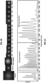
- Fig. 3 depicts the SLM control over of the cascade as the nonlinear interaction in the MMF were selectively tuned.
- Fig. 3A-3C the 3 rd SRS, 4 th SRS, and 5 th SRS peak optimization results are illustrated.
- the square marks the spectral region of interest for each optimization.
- a flat phase on the SLM is compared to the optimal phase mask.
- Th input energy was kept constant for comparison.
- a 0.14NA objective was used with a pulse energy of 18 ⁇ J.
- the SRS cascade can be generated in several low order modes, as depicted in the near-field images of SRS 543nm peak modes in a 20m GRIN fiber as shown in Fig. 3D .
- the most efficient cascade is generated once the fundamental mode is excited.
- the mode-cleaned pump overlaps spatially with the generated Stokes wave and the cascade keeps generating clean fundamental modes of higher wavelengths.
- the SLM optimizes the input superposition of modes for fundamental mode excitation, compensates for aberrations in the optical system, and enables dynamic feedback monitoring on the SRS cascade.
- the optimization of the SRS cascade efficiency is a rather simple example because it does not include complex modal excitation.
- the SRS interplay with FWM illustrates more complex intermodal phase matching. Such is the case in the next experiment where an SRS cascade was generated in a 1km long GRIN MMF and demonstrate spectral shifting of each peak of the cascade. The spectral shifts occur as the input excitation of the fiber is continually tuned from the optimized fundamental mode (longer SRS wavelengths) to a mixed mode excitation (SRS wavelengths downshift). At mixed modal excitation, the interplay of FWM becomes dominant and mediates the SRS cascade.
- the SLM provides continuous control over the spectrum to produce the desired output by controlling the mixture of modes at the input of the MMF.
- the spectral shifts of the cascade are obtained by mixed-mode excitation.
- the GA provides an optimized collection of modes on the SLM that generates a selective FWM interaction to pull the average wavelength down. Similar spectral-shifts can be achieved by manually adjusting the input coupling of the fiber.
- the SLM provides a systematic and controlled feedback methodology that allows precise modal excitation for the desired results.
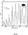
- Figs. 4A-4B illustrate wavefront shaping of spectral shifts according to one or more embodiments of the present technology.
- Fig. 4A represents the optimization of shifts towards lower wavelength and mixed mode excitation.
- the GA optimization process generated shifts of up to 20nm.
- the spectrum is continually shifted with the excitation of higher order modes that supported FWM processes along the SRS cascade.
- the rectangle shows the selected spectral region of interest.
- the plot shows the GA performance and the bottom-right insert depicts the optimized phase mask.
- a 0.14NA objective was used with laser pulse energy of 50 ⁇ J.
- a tunable source based on nonlinear WFS control could be beneficial for various laser applications.
- nonlinearities limit the information capacity of fiber networks. Suppression of nonlinearity is therefore highly desirable for the constantly growing bandwidth demand.
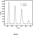
- I SRS appears inverted and normalized, while I out is normalized.
- the fiber transmission, I out is measured at the output before spectral filtering and its place in the figure-of-merit assures that the suppression of SRS is the result of high-mode excitation and not simply decoupling of light by diffraction on the SLM.
- some embodiments may weight the two optimization components equally, but it is possible to choose a different weighting function
- the total transmission was measured before and after optimization to normalize any diffraction effects in the suppression experiment.
- the projected phase pattern decreased the total transmission by 10%, compared to an averaged random-phase (initial mask in the GA process) and by 66%, compared to the flat-phase-transmission.
- the laser energy was reduced by 66%, compared to the power used in the optimization, and plotted the flat-phase output with identical total transmission to the optimized-phase mask.
- the optimization of the embodiments used suppressed the SRS cascade by a factor of x52. This value represents the ratio of the integrated SRS cascade spectra for the normalized flat- phase and optimized-phase cases.
- Fig. 5B shows the WFS enhancement of the figure-of-merit with iteration number.
- the dramatic, x7, suppression of the SRS cascade from the initial random pattern shows that optimizing the higher order mode superposition is significantly more effective than a non-optimized speckle pattern, such as could be achieved with a simple NA-matched diffuser.
- the WFS control of various nonlinear processes used in various embodiments enables spectral shaping via the coupled spatial modal control.
- the effect of WFS becomes more noticeable.
- Fiber cut-back experiments show that ⁇ 50m fibers support several SRS modes while in the longer fibers, mostly the fundamental clean mode appears, hinting that a mode competition occurs along the length of the fiber.
- Even with short fibers of ⁇ 5m the most efficient SRS cascades occur once the fundamental mode is excited efficiently.
- WFS provides a controlled way for enhancing the mode excitation.
- WFS enables control over FWM, spectral shifting, and nonlinearities suppression by coupling a tailored superposition of modes into the fiber. All of these phenomena and capabilities are attained beyond the capabilities of simple lens-coupling.
- GRIN fibers have unique properties for generating interesting nonlinear interactions not always shared by step-index fibers. For instance, step-index fibers (50 microns, 10m) have been tested and could not attain SRS nor FWM with the maximal laser power.
- the number of macro-pixels utilized in the SLM has to be carefully considered. Once phase patterns are displayed, some of the light is diffracted out of the fiber, reducing the coupled input power and decreasing the nonlinearity regardless of the particular modes excited. As the number of SLM macro-pixels increases, the diffraction spectrum broadens, further reducing the input power coupling. In order to limit this unwanted diffraction, the number of SLM macro-pixels was limited between 64-1024, and each phase pattern was slightly low-pass digitally filtered to smooth the phase edges. After taking into account the diffraction decoupling effects and strict criteria, namely a constant laser power for enhancement and a normalized coupling power into the fiber for suppression, as described above.
- Thermal management plays an interesting role in the SRS cascade.
- the coupling of thermal effects was the primary concern with optimization of the efficiency of nonlinearities.
- some embodiments align a short fiber in an aluminum v-shaped profile and immersed the fiber in water-based gel. This configuration can allow for improved thermal management, and can be compared the flat phase spectrum before and after optimization to ensure that the thermal management keeps the fiber at the same conditions over time and during WFS.
- liquid-crystal SLMs and other phase modulators are subject to optical damage in high-power applications. Proper precautions ensure safe operation with a high-power ns laser.
- nonlinear MMF requires long term stability of the system.
- an active device such as an SLM, allows degree of dynamic control that maintains operation over long periods of time compensating for mechanical and thermal drifts.
- Such techniques open up a new field of adaptive nonlinear optics.
- WFS controls systems with different types of nonlinearity.
- Some experiments in a specific regime were evaluated: wavelength of 532nm, normal dispersion in the fiber, and ns pulses where group-velocity-dispersion effects are of minor importance.
- Various embodiments provide several important applications of WFS control in nonlinear MMF including enhancement, shifting and suppression of SRS and FWM.
- Various embodiments provide for WFS control and optimization of nonlinear interactions in MMF.
- WFS control and optimization of nonlinear interactions in MMF By optimizing the input phase of the fiber-coupled wavefront, the energy of selected SRS and FWM peaks can be tuned creating a configurable source with tailored performance.
- the adaptive in-line optimization represents an approach to solve the nonlinear inverse problem of finding a tailored superposition of modes at the input of the fiber for a desired spectral output.
- the GA optimization for WFS used in some embodiments can start with a population set of random phase masks (e.g., 30) and iteratively converges to an optimized pattern.
- a phase mask is displayed on the SLM and a merit signal is recorded, based on a specified spectral analysis at the fiber's output.
- the recorded values of the initial population are ranked based on the selected figure-of-merit and a new generation, containing new phase masks (e.g., 15 off-springs) is created.
- the breeding process combines two phase masks from the population, which are randomly chosen with a probability weighted by the ranking.
- a new phase mask can be displayed on the SLM and the corresponding figure-of-merit can be recorded.
- the ranking and breeding process repeats itself every cycle (e.g., 15 measurements), always keeping the highest ranked phase-masks (e.g., 30) as the population for the next iteration.
- the effective index diagram depicts the GRIN mode groups as a function of the radial frequency ⁇ .
- the refractive index diagram highlights the material dispersion that is compensated via modal phase matching. Therefore, the require phase-matching conditions on the refractive index diagram are illustrated.
- ⁇ lm n lm ⁇ ⁇ c Is a direct representation of the momentum and appropriate for phase-matching calculations.
- the FWM process in MMF can be described by the coupled amplitude equations of the nonlinear process (under quasi CW conditions).
- Power handling measurements with pulsed lasers can be performed periodically in some embodiments and compared between measurements to ensure safe SLM operation.
- the SLM monitoring optical setup used in some embodiments is depicted in supplementary Fig. 7 .
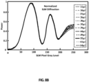
- a checkerboard pattern (2D grating) was written to the SLM and the 1st diffraction order intensity was collected as the difference in phase in the grating was varied from 0 to just over 1 wave (2 ⁇ phase).
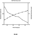
- Figs. 8A-8D show a typical series of characterization curves, with increasing laser power. A slight shift, less than five SLM-pixel-gray-level, in the phase response as a function of incident power is observed. This shift is a result of thermal effects and it is reversible at suitable power densities. Reduced modulation depth, less than 2%, with laser power can also be observed.
- Computers may employ central processing unit (CPU) or processor to process information.
- Processors may include programmable general-purpose or special-purpose microprocessors, programmable controllers, application-specific integrated circuits (ASICs), programmable logic devices (PLDs), embedded components, combination of such devices and the like.
- ASICs application-specific integrated circuits
- PLDs programmable logic devices
- Processors execute program components in response to user and/or system-generated requests.
- One or more of these components may be implemented in software, hardware or both hardware and software.
- Processors pass instructions (e.g., operational and data instructions) to enable various operations.
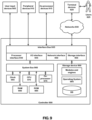
- the controller 900 may include clock 965, CPU 970, memory such as read only memory (ROM) 985 and random access memory (RAM) 980 and co-processor 975 among others. These controller components may be connected to a system bus 960, and through the system bus 960 to an interface bus 935. Further, user input devices 905, peripheral devices 910, co-processor devices 915, and the like, may be connected through the interface bus 935 to the system bus 960.
- the interface bus 935 may be connected to a number of interface adapters such as processor interface 940, input output interfaces (I/O) 945, network interfaces 950, storage interfaces 955, and the like.
- Processor interface 940 may facilitate communication between co-processor devices 915 and co-processor 975. In one implementation, processor interface 940 may expedite encryption and decryption of requests or data.
- I/O Input output interfaces
- I/O 945 facilitate communication between user input devices 905, peripheral devices 910, co-processor devices 915, and/or the like and components of the controller 900 using protocols such as those for handling audio, data, video interface, wireless transceivers, or the like (e.g., Bluetooth, IEEE 1394a-b, serial, universal serial bus (USB), Digital Visual Interface (DVI), 802.11a/b/g/n/x, cellular, etc.).
- Network interfaces 950 may be in communication with the network 930. Through the network 930, the controller 900 may be accessible to remote terminal devices 920.
- Network interfaces 950 may use various wired and wireless connection protocols such as, direct connect, Ethernet, wireless connection such as IEEE 802.11a-x, and the like.
- the firewall may additionally manage and/or have access to an access control list which details permissions including, for example, the access and operation rights of an object by an individual, a machine, and/or an application, and the circumstances under which the permission rights stand.
- Other network security functions performed or included in the functions of the firewall can be, for example, but are not limited to, intrusion-prevention, intrusion detection, next-generation firewall, personal firewall, etc., without deviating from the novel art of this disclosure.
- Storage interfaces 955 may be in communication with a number of storage devices such as, storage devices 990, removable disc devices, and the like.
- the storage interfaces 955 may use various connection protocols such as Serial Advanced Technology Attachment (SATA), IEEE 1394, Ethernet, Universal Serial Bus (USB), and the like.
- SATA Serial Advanced Technology Attachment
- IEEE 1394 IEEE 1394
- Ethernet Ethernet
- USB Universal Serial Bus
- Computer executable instructions and data may be stored in memory (e.g., registers, cache memory, random access memory, flash, etc.) which is accessible by processors. These stored instruction codes (e.g., programs) may engage the processor components, motherboard and/or other system components to perform desired operations.
- the controller 900 may employ various forms of memory including on-chip CPU memory (e.g., registers), RAM 980, ROM 985, and storage devices 990.
- Storage devices 990 may employ any number of tangible, non-transitory storage devices or systems such as fixed or removable magnetic disk drive, an optical drive, solid state memory devices and other processor-readable storage media.
- Computer-executable instructions stored in the memory may include one or more program modules such as routines, programs, objects, components, data structures, and so on that perform particular tasks or implement particular abstract data types.
- the memory may contain operating system (OS) component 995, modules and other components, database tables, and the like. These modules/components may be stored and accessed from the storage devices, including from external storage devices accessible through an interface bus.
- OS operating system
- the controller 900 may be implemented in distributed computing environments, where tasks or modules are performed by remote processing devices, which are linked through a communications network, such as a Local Area Network ("LAN”), Wide Area Network ("WAN”), the Internet, and the like.
- LAN Local Area Network
- WAN Wide Area Network
- program modules or subroutines may be located in both local and remote memory storage devices.
- Distributed computing may be employed to load balance and/or aggregate resources for processing.
- aspects of the controller 900 may be distributed electronically over the Internet or over other networks (including wireless networks).
- portions of the system may reside on a server computer, while corresponding portions reside on a client computer. Data structures and transmission of data particular to aspects of the controller 900 are also encompassed within the scope of the disclosure.
- the words “comprise,” “comprising,” and the like are to be construed in an inclusive sense, as opposed to an exclusive or exhaustive sense; that is to say, in the sense of "including, but not limited to.”
- the terms “connected,” “coupled,” or any variant thereof means any connection or coupling, either direct or indirect, between two or more elements; the coupling or connection between the elements can be physical, logical, or a combination thereof.
- the words “herein,” “above,” “below,” and words of similar import, when used in this application refer to this application as a whole and not to any particular portions of this application.
Landscapes
- Physics & Mathematics (AREA)
- Nonlinear Science (AREA)
- General Physics & Mathematics (AREA)
- Optics & Photonics (AREA)
- Chemical & Material Sciences (AREA)
- Health & Medical Sciences (AREA)
- Crystallography & Structural Chemistry (AREA)
- Life Sciences & Earth Sciences (AREA)
- Analytical Chemistry (AREA)
- Biochemistry (AREA)
- General Health & Medical Sciences (AREA)
- Immunology (AREA)
- Pathology (AREA)
- Engineering & Computer Science (AREA)
- Signal Processing (AREA)
- Nuclear Medicine, Radiotherapy & Molecular Imaging (AREA)
- Mathematical Physics (AREA)
- Spectroscopy & Molecular Physics (AREA)
- Optical Modulation, Optical Deflection, Nonlinear Optics, Optical Demodulation, Optical Logic Elements (AREA)
Claims (10)
- Système de commande de la distribution spatiale, spectrale, de polarisation et/ou temporelle de la lumière, le système comprenant :une source de lumière (105) configurée pour générer une lumière ;un modulateur spatial de lumière (115) ayant un masque variable pour modifier une ou plusieurs propriétés de la lumière générée par la source de lumière ;un support (130) ayant une extrémité proximale (125) pour recevoir une lumière modifiée du modulateur spatial de lumière et guider la lumière modifiée vers une extrémité distale ;un système de détection (135, 140, 145, 175) pour évaluer la ou les plusieurs propriétés produites par la lumière modifiée au niveau de l'extrémité distale du support ; etun système de commande couplé en communication au modulateur spatial de lumière et au système de détection, configuré pour :évaluer la ou les plusieurs propriétés produites par la lumière modifiée au niveau de l'extrémité distale du support ;générer un masque mis à jour qui améliore la ou les plusieurs propriétés de la lumière modifiée au niveau de l'extrémité distale du support ; ettransmettre un signal au modulateur spatial de lumière pour mettre en œuvre le masque mis à jour,caractérisé en ce quele système de commande commande au moins l'une des propriétés suivantes : une polarisation d'une lumière de sortie et une forme d'impulsion et une durée de la lumière de sortie.
- Système de la revendication 1, dans lequel la source de lumière est un laser pulsé tel qu'un laser pulsé nanoseconde, un laser pulsé picoseconde ou un laser pulsé femtoseconde.
- Système de la revendication 1, dans lequel le système de détection est au moins l'un parmi un spectromètre (175), un réseau de détecteurs, une caméra (135, 140), un photodétecteur (145), un autocorrélateur ou un système de caractérisation d'impulsions.
- Système de la revendication 1, dans lequel le support configuré pour transmettre la lumière est un guide d'ondes, une fibre multicœur, un réseau de guides d'ondes ou une fibre multimode.
- Système de la revendication 1, dans lequel :le modulateur spatial de lumière est un modulateur spatial de lumière à cristaux liquides, un miroir déformable, un projecteur de lumière numérique ou un miroir segmenté ; et/oule modulateur spatial de lumière comprend des macro-pixels indépendants dont la phase varie entre zéro et 2π.
- Système de la revendication 1, dans lequel :
le système de commande génère le masque mis à jour en utilisant un algorithme d'optimisation, un algorithme génétique ou un algorithme d'apprentissage automatique qui optimise une fonction objective. - Procédé de mise en forme d'une dynamique multimode dans un support de transmission, le procédé comprenant :la mesure d'une propriété d'une lumière au niveau d'une extrémité distale d'un support de transmission ;la sélection, en utilisant une unité de commande, d'un masque de phase pour mettre en forme la propriété de la lumière telle que mesurée au niveau de l'extrémité distale du support de transmission ; etla transmission d'instructions à un modulateur spatial de lumière en vue d'appliquer le masque de phase à une lumière d'entrée générée par une source de lumière pour régler de manière sélective les interactions non linéaires dans le support de transmission,caractérisé en ce quel'unité de commande commande au moins l'une des propriétés suivantes : une polarisation d'une lumière de sortie et une forme d'impulsion ou une durée de la lumière de sortie.
- Procédé de la revendication 7,le procédé comprenant en outre le filtrage de la lumière au niveau de l'extrémité distale du support de transmission ; et/oudans lequel la lumière est utilisée pour transmettre des informations ; et/ou dans lequel le procédé est mis en œuvre dans le cadre d'un système laser ; et dans lequel le procédé met en œuvre un réseau neuronal artificiel.
- Procédé de la revendication 7, dans lequel le support de transmission comprend un guide d'ondes, une fibre multimode, une fibre multicœur, un réseau de guides d'ondes, une fibre à saut d'indice ou une fibre à indice gradué, GRIN.
- Procédé de la revendication 7, comprenant en outre la génération de la lumière en utilisant un laser pulsé femtoseconde, un laser pulsé picoseconde ou un laser pulsé nanoseconde.
Applications Claiming Priority (2)
| Application Number | Priority Date | Filing Date | Title |
|---|---|---|---|
| US201762533900P | 2017-07-18 | 2017-07-18 | |
| PCT/US2018/042742 WO2019018558A1 (fr) | 2017-07-18 | 2018-07-18 | Procédés et systèmes de commande de transmission de lumière non linéaire |
Publications (4)
| Publication Number | Publication Date |
|---|---|
| EP3655811A1 EP3655811A1 (fr) | 2020-05-27 |
| EP3655811A4 EP3655811A4 (fr) | 2021-04-21 |
| EP3655811C0 EP3655811C0 (fr) | 2025-03-12 |
| EP3655811B1 true EP3655811B1 (fr) | 2025-03-12 |
Family
ID=65016135
Family Applications (1)
| Application Number | Title | Priority Date | Filing Date |
|---|---|---|---|
| EP18836204.0A Active EP3655811B1 (fr) | 2017-07-18 | 2018-07-18 | Procédés et systèmes de commande de transmission de lumière non linéaire |
Country Status (3)
| Country | Link |
|---|---|
| US (2) | US10514586B2 (fr) |
| EP (1) | EP3655811B1 (fr) |
| WO (1) | WO2019018558A1 (fr) |
Families Citing this family (7)
| Publication number | Priority date | Publication date | Assignee | Title |
|---|---|---|---|---|
| US10365606B2 (en) * | 2017-04-07 | 2019-07-30 | Thanh Nguyen | Apparatus, optical system, and method for digital holographic microscopy |
| CN109633885A (zh) * | 2019-01-29 | 2019-04-16 | 清华大学 | 基于波前聚焦的梯度折射率透镜显微成像系统及方法 |
| CN109782394A (zh) * | 2019-03-15 | 2019-05-21 | 杭州芯耘光电科技有限公司 | 一种单光纤双向光收发组件 |
| US11237111B2 (en) * | 2020-01-30 | 2022-02-01 | Trustees Of Boston University | High-speed delay scanning and deep learning techniques for spectroscopic SRS imaging |
| CN113630517B (zh) | 2021-10-08 | 2022-01-25 | 清华大学 | 光电感算一体光场智能成像方法及装置 |
| CN114024810B (zh) * | 2021-11-03 | 2023-05-23 | 南京信息工程大学 | 一种多芯光纤信道调制格式识别方法及其装置 |
| CN116108156B (zh) * | 2023-04-07 | 2023-06-09 | 四川大学 | 一种基于循环关联鲁棒学习的主题法条检索方法 |
Family Cites Families (10)
| Publication number | Priority date | Publication date | Assignee | Title |
|---|---|---|---|---|
| US6663560B2 (en) | 1999-12-17 | 2003-12-16 | Digital Optical Imaging Corporation | Methods and apparatus for imaging using a light guide bundle and a spatial light modulator |
| FR2834349B1 (fr) | 2001-12-28 | 2004-04-09 | Mauna Kea Technologies | Appareillage d'imagerie confocale notamment pour endoscope |
| US9074936B2 (en) * | 2007-07-31 | 2015-07-07 | Massachusetts Institute Of Technology | Multidimensional pulse shaper and spectrometer |
| EP3657228A1 (fr) * | 2009-07-09 | 2020-05-27 | Howard Hughes Medical Institute | Microscopie avec optique adaptative |
| WO2013185087A1 (fr) * | 2012-06-07 | 2013-12-12 | The Trustees Of Dartmouth College | Procédés et systèmes pour l'évaluation de marge de tumeur peropératoire dans des cavités chirurgicales et des échantillons de tissu réséqué |
| US20140235948A1 (en) | 2013-02-19 | 2014-08-21 | The Board Of Trustees Of The Leland Stanford Junior University | Method for single-fiber microscopy using intensity-pattern sampling and optimization-based reconstruction |
| JP6501451B2 (ja) * | 2014-03-31 | 2019-04-17 | キヤノン株式会社 | 光源装置およびそれを用いた情報取得装置 |
| US10254534B2 (en) | 2015-11-30 | 2019-04-09 | The Regents Of The University Of Colorado, A Body Corporate | Single multimode fiber endoscope |
| JP6768289B2 (ja) * | 2015-12-01 | 2020-10-14 | キヤノン株式会社 | 走査型顕微鏡 |
| US10901240B2 (en) * | 2016-02-04 | 2021-01-26 | Massachusetts Institute Of Technology | Electro-Optic beam controller and method |
-
2018
- 2018-07-18 US US16/039,156 patent/US10514586B2/en active Active
- 2018-07-18 WO PCT/US2018/042742 patent/WO2019018558A1/fr not_active Ceased
- 2018-07-18 EP EP18836204.0A patent/EP3655811B1/fr active Active
-
2019
- 2019-12-20 US US16/723,196 patent/US11768420B2/en active Active
Non-Patent Citations (1)
| Title |
|---|
| TZANG OMER ET AL: "Wave-front shaping in nonlinear multimode fibers", 18 January 2017 (2017-01-18), pages 1 - 11, XP055783648, Retrieved from the Internet <URL:https://arxiv.org/ftp/arxiv/papers/1701/1701.05260.pdf> [retrieved on 20210309] * |
Also Published As
| Publication number | Publication date |
|---|---|
| EP3655811A1 (fr) | 2020-05-27 |
| US20190025668A1 (en) | 2019-01-24 |
| EP3655811A4 (fr) | 2021-04-21 |
| US11768420B2 (en) | 2023-09-26 |
| US10514586B2 (en) | 2019-12-24 |
| EP3655811C0 (fr) | 2025-03-12 |
| US20200249541A1 (en) | 2020-08-06 |
| WO2019018558A1 (fr) | 2019-01-24 |
Similar Documents
| Publication | Publication Date | Title |
|---|---|---|
| EP3655811B1 (fr) | Procédés et systèmes de commande de transmission de lumière non linéaire | |
| Wright et al. | Physics of highly multimode nonlinear optical systems | |
| Tzang et al. | Adaptive wavefront shaping for controlling nonlinear multimode interactions in optical fibres | |
| Pourbeyram et al. | Direct observations of thermalization to a Rayleigh–Jeans distribution in multimode optical fibres | |
| Krupa et al. | Multimode nonlinear fiber optics, a spatiotemporal avenue | |
| Krupa et al. | Spatial beam self-cleaning in multimode fibres | |
| Wright et al. | Self-organized instability in graded-index multimode fibres | |
| US8290317B2 (en) | Production of optical pulses at a desired wavelength utilizing higher-order-mode (HOM) fiber | |
| Ghanbari et al. | Supercontinuum generation for optical coherence tomography using magnesium fluoride photonic crystal fiber | |
| Qiu et al. | Spectral-temporal-spatial customization via modulating multimodal nonlinear pulse propagation | |
| EP2856243B1 (fr) | Procédé d'amélioration de la luminosité et de modification de la structure modale dans une fibre optique multimode | |
| Saghaei et al. | White light generation using photonic crystal fiber with sub-micron circular lattice | |
| Chen et al. | Suppressing transverse mode instability through multimode excitation in a fiber amplifier | |
| Goyal et al. | Controlling optical similaritons in a graded-index nonlinear waveguide by tailoring of the tapering profile | |
| Karim et al. | Study of highly coherent mid-infrared supercontinuum generation in CMOS compatible Si-rich SiN tapered waveguide | |
| Lou et al. | Ultrafast flat-top beam emission with an all-fiber multimode laser | |
| Alamgir et al. | Supercontinuum generation optimization in a dispersion-varying chalcogenide fiber | |
| He et al. | Cascaded Kerr beam self-cleaning in graded-index multimode fibers | |
| Shekel et al. | Tutorial: How to build and control an all-fiber wavefront modulator using mechanical perturbations | |
| Mohammadzahery et al. | Nonlinear spatial reshaping of pulsed beam in a step-index few-mode optical fiber | |
| Tzang et al. | Wave-front shaping in nonlinear multimode fibers | |
| Sader et al. | Modulation instability control via evolutionarily optimized optical seeding | |
| Li et al. | Spatial coherence measurement of supercontinuum generation in graded-index multimode fibers in the anomalous dispersion regime | |
| Hesami et al. | Dark spatial soliton and quasi-soliton by arbitrary initial beam profiles in negative Kerr local and nonlocal medium | |
| Gervaziev et al. | Mode decomposition method for investigating the nonlinear dynamics of a multimode beam |
Legal Events
| Date | Code | Title | Description |
|---|---|---|---|
| STAA | Information on the status of an ep patent application or granted ep patent |
Free format text: STATUS: THE INTERNATIONAL PUBLICATION HAS BEEN MADE |
|
| PUAI | Public reference made under article 153(3) epc to a published international application that has entered the european phase |
Free format text: ORIGINAL CODE: 0009012 |
|
| STAA | Information on the status of an ep patent application or granted ep patent |
Free format text: STATUS: REQUEST FOR EXAMINATION WAS MADE |
|
| 17P | Request for examination filed |
Effective date: 20200217 |
|
| AK | Designated contracting states |
Kind code of ref document: A1 Designated state(s): AL AT BE BG CH CY CZ DE DK EE ES FI FR GB GR HR HU IE IS IT LI LT LU LV MC MK MT NL NO PL PT RO RS SE SI SK SM TR |
|
| AX | Request for extension of the european patent |
Extension state: BA ME |
|
| DAV | Request for validation of the european patent (deleted) | ||
| DAX | Request for extension of the european patent (deleted) | ||
| A4 | Supplementary search report drawn up and despatched |
Effective date: 20210319 |
|
| RIC1 | Information provided on ipc code assigned before grant |
Ipc: G02B 23/24 20060101AFI20210315BHEP Ipc: G02B 6/028 20060101ALI20210315BHEP Ipc: G02B 23/26 20060101ALI20210315BHEP Ipc: H04N 5/225 20060101ALI20210315BHEP Ipc: H04N 5/247 20060101ALI20210315BHEP Ipc: G01J 3/02 20060101ALI20210315BHEP |
|
| STAA | Information on the status of an ep patent application or granted ep patent |
Free format text: STATUS: EXAMINATION IS IN PROGRESS |
|
| 17Q | First examination report despatched |
Effective date: 20230222 |
|
| REG | Reference to a national code |
Ref country code: DE Ref legal event code: R079 Free format text: PREVIOUS MAIN CLASS: G02B0023240000 Ipc: G02F0001365000 Ref country code: DE Ref legal event code: R079 Ref document number: 602018080096 Country of ref document: DE Free format text: PREVIOUS MAIN CLASS: G02B0023240000 Ipc: G02F0001365000 |
|
| GRAP | Despatch of communication of intention to grant a patent |
Free format text: ORIGINAL CODE: EPIDOSNIGR1 |
|
| STAA | Information on the status of an ep patent application or granted ep patent |
Free format text: STATUS: GRANT OF PATENT IS INTENDED |
|
| RIC1 | Information provided on ipc code assigned before grant |
Ipc: G02F 1/365 20060101AFI20240723BHEP |
|
| INTG | Intention to grant announced |
Effective date: 20240805 |
|
| GRAS | Grant fee paid |
Free format text: ORIGINAL CODE: EPIDOSNIGR3 |
|
| GRAA | (expected) grant |
Free format text: ORIGINAL CODE: 0009210 |
|
| STAA | Information on the status of an ep patent application or granted ep patent |
Free format text: STATUS: THE PATENT HAS BEEN GRANTED |
|
| AK | Designated contracting states |
Kind code of ref document: B1 Designated state(s): AL AT BE BG CH CY CZ DE DK EE ES FI FR GB GR HR HU IE IS IT LI LT LU LV MC MK MT NL NO PL PT RO RS SE SI SK SM TR |
|
| REG | Reference to a national code |
Ref country code: GB Ref legal event code: FG4D |
|
| REG | Reference to a national code |
Ref country code: CH Ref legal event code: EP |
|
| REG | Reference to a national code |
Ref country code: DE Ref legal event code: R096 Ref document number: 602018080096 Country of ref document: DE |
|
| REG | Reference to a national code |
Ref country code: IE Ref legal event code: FG4D |
|
| U01 | Request for unitary effect filed |
Effective date: 20250314 |
|
| U07 | Unitary effect registered |
Designated state(s): AT BE BG DE DK EE FI FR IT LT LU LV MT NL PT RO SE SI Effective date: 20250321 |
|
| PG25 | Lapsed in a contracting state [announced via postgrant information from national office to epo] |
Ref country code: RS Free format text: LAPSE BECAUSE OF FAILURE TO SUBMIT A TRANSLATION OF THE DESCRIPTION OR TO PAY THE FEE WITHIN THE PRESCRIBED TIME-LIMIT Effective date: 20250612 |
|
| PG25 | Lapsed in a contracting state [announced via postgrant information from national office to epo] |
Ref country code: ES Free format text: LAPSE BECAUSE OF FAILURE TO SUBMIT A TRANSLATION OF THE DESCRIPTION OR TO PAY THE FEE WITHIN THE PRESCRIBED TIME-LIMIT Effective date: 20250312 |
|
| PG25 | Lapsed in a contracting state [announced via postgrant information from national office to epo] |
Ref country code: NO Free format text: LAPSE BECAUSE OF FAILURE TO SUBMIT A TRANSLATION OF THE DESCRIPTION OR TO PAY THE FEE WITHIN THE PRESCRIBED TIME-LIMIT Effective date: 20250612 |
|
| PG25 | Lapsed in a contracting state [announced via postgrant information from national office to epo] |
Ref country code: HR Free format text: LAPSE BECAUSE OF FAILURE TO SUBMIT A TRANSLATION OF THE DESCRIPTION OR TO PAY THE FEE WITHIN THE PRESCRIBED TIME-LIMIT Effective date: 20250312 |
|
| PG25 | Lapsed in a contracting state [announced via postgrant information from national office to epo] |
Ref country code: GR Free format text: LAPSE BECAUSE OF FAILURE TO SUBMIT A TRANSLATION OF THE DESCRIPTION OR TO PAY THE FEE WITHIN THE PRESCRIBED TIME-LIMIT Effective date: 20250613 |
|
| U20 | Renewal fee for the european patent with unitary effect paid |
Year of fee payment: 8 Effective date: 20250728 |
|
| PG25 | Lapsed in a contracting state [announced via postgrant information from national office to epo] |
Ref country code: SM Free format text: LAPSE BECAUSE OF FAILURE TO SUBMIT A TRANSLATION OF THE DESCRIPTION OR TO PAY THE FEE WITHIN THE PRESCRIBED TIME-LIMIT Effective date: 20250312 |
|
| PG25 | Lapsed in a contracting state [announced via postgrant information from national office to epo] |
Ref country code: PL Free format text: LAPSE BECAUSE OF FAILURE TO SUBMIT A TRANSLATION OF THE DESCRIPTION OR TO PAY THE FEE WITHIN THE PRESCRIBED TIME-LIMIT Effective date: 20250312 |
|
| PGFP | Annual fee paid to national office [announced via postgrant information from national office to epo] |
Ref country code: GB Payment date: 20250728 Year of fee payment: 8 |
|
| PG25 | Lapsed in a contracting state [announced via postgrant information from national office to epo] |
Ref country code: CZ Free format text: LAPSE BECAUSE OF FAILURE TO SUBMIT A TRANSLATION OF THE DESCRIPTION OR TO PAY THE FEE WITHIN THE PRESCRIBED TIME-LIMIT Effective date: 20250312 |
|
| PG25 | Lapsed in a contracting state [announced via postgrant information from national office to epo] |
Ref country code: SK Free format text: LAPSE BECAUSE OF FAILURE TO SUBMIT A TRANSLATION OF THE DESCRIPTION OR TO PAY THE FEE WITHIN THE PRESCRIBED TIME-LIMIT Effective date: 20250312 |
|
| PG25 | Lapsed in a contracting state [announced via postgrant information from national office to epo] |
Ref country code: IS Free format text: LAPSE BECAUSE OF FAILURE TO SUBMIT A TRANSLATION OF THE DESCRIPTION OR TO PAY THE FEE WITHIN THE PRESCRIBED TIME-LIMIT Effective date: 20250712 |
|
| PLBE | No opposition filed within time limit |
Free format text: ORIGINAL CODE: 0009261 |
|
| STAA | Information on the status of an ep patent application or granted ep patent |
Free format text: STATUS: NO OPPOSITION FILED WITHIN TIME LIMIT |
|
| REG | Reference to a national code |
Ref country code: CH Ref legal event code: L10 Free format text: ST27 STATUS EVENT CODE: U-0-0-L10-L00 (AS PROVIDED BY THE NATIONAL OFFICE) Effective date: 20260121 |
|
| 26N | No opposition filed |
Effective date: 20251215 |
|
| REG | Reference to a national code |
Ref country code: CH Ref legal event code: H13 Free format text: ST27 STATUS EVENT CODE: U-0-0-H10-H13 (AS PROVIDED BY THE NATIONAL OFFICE) Effective date: 20260224 |
|
| PG25 | Lapsed in a contracting state [announced via postgrant information from national office to epo] |
Ref country code: CH Free format text: LAPSE BECAUSE OF NON-PAYMENT OF DUE FEES Effective date: 20250731 |