EP3655822B1 - System und verfahren zur direkten härtung von photopolymerdruckplatten - Google Patents
System und verfahren zur direkten härtung von photopolymerdruckplatten Download PDFInfo
- Publication number
- EP3655822B1 EP3655822B1 EP18750354.5A EP18750354A EP3655822B1 EP 3655822 B1 EP3655822 B1 EP 3655822B1 EP 18750354 A EP18750354 A EP 18750354A EP 3655822 B1 EP3655822 B1 EP 3655822B1
- Authority
- EP
- European Patent Office
- Prior art keywords
- printing plate
- plate
- radiation source
- radiation
- photopolymer
- Prior art date
- Legal status (The legal status is an assumption and is not a legal conclusion. Google has not performed a legal analysis and makes no representation as to the accuracy of the status listed.)
- Active
Links
Images
Classifications
-
- G—PHYSICS
- G03—PHOTOGRAPHY; CINEMATOGRAPHY; ANALOGOUS TECHNIQUES USING WAVES OTHER THAN OPTICAL WAVES; ELECTROGRAPHY; HOLOGRAPHY
- G03F—PHOTOMECHANICAL PRODUCTION OF TEXTURED OR PATTERNED SURFACES, e.g. FOR PRINTING, FOR PROCESSING OF SEMICONDUCTOR DEVICES; MATERIALS THEREFOR; ORIGINALS THEREFOR; APPARATUS SPECIALLY ADAPTED THEREFOR
- G03F7/00—Photomechanical, e.g. photolithographic, production of textured or patterned surfaces, e.g. printing surfaces; Materials therefor, e.g. comprising photoresists; Apparatus specially adapted therefor
- G03F7/20—Exposure; Apparatus therefor
- G03F7/2051—Exposure without an original mask, e.g. using a programmed deflection of a point source, by scanning, by drawing with a light beam, using an addressed light or corpuscular source
- G03F7/2053—Exposure without an original mask, e.g. using a programmed deflection of a point source, by scanning, by drawing with a light beam, using an addressed light or corpuscular source using a laser
- G03F7/2055—Exposure without an original mask, e.g. using a programmed deflection of a point source, by scanning, by drawing with a light beam, using an addressed light or corpuscular source using a laser for the production of printing plates; Exposure of liquid photohardening compositions
-
- G—PHYSICS
- G03—PHOTOGRAPHY; CINEMATOGRAPHY; ANALOGOUS TECHNIQUES USING WAVES OTHER THAN OPTICAL WAVES; ELECTROGRAPHY; HOLOGRAPHY
- G03F—PHOTOMECHANICAL PRODUCTION OF TEXTURED OR PATTERNED SURFACES, e.g. FOR PRINTING, FOR PROCESSING OF SEMICONDUCTOR DEVICES; MATERIALS THEREFOR; ORIGINALS THEREFOR; APPARATUS SPECIALLY ADAPTED THEREFOR
- G03F7/00—Photomechanical, e.g. photolithographic, production of textured or patterned surfaces, e.g. printing surfaces; Materials therefor, e.g. comprising photoresists; Apparatus specially adapted therefor
- G03F7/20—Exposure; Apparatus therefor
- G03F7/2002—Exposure; Apparatus therefor with visible light or UV light, through an original having an opaque pattern on a transparent support, e.g. film printing, projection printing; by reflection of visible or UV light from an original such as a printed image
- G03F7/2012—Exposure; Apparatus therefor with visible light or UV light, through an original having an opaque pattern on a transparent support, e.g. film printing, projection printing; by reflection of visible or UV light from an original such as a printed image using liquid photohardening compositions, e.g. for the production of reliefs such as flexographic plates or stamps
-
- G—PHYSICS
- G03—PHOTOGRAPHY; CINEMATOGRAPHY; ANALOGOUS TECHNIQUES USING WAVES OTHER THAN OPTICAL WAVES; ELECTROGRAPHY; HOLOGRAPHY
- G03F—PHOTOMECHANICAL PRODUCTION OF TEXTURED OR PATTERNED SURFACES, e.g. FOR PRINTING, FOR PROCESSING OF SEMICONDUCTOR DEVICES; MATERIALS THEREFOR; ORIGINALS THEREFOR; APPARATUS SPECIALLY ADAPTED THEREFOR
- G03F7/00—Photomechanical, e.g. photolithographic, production of textured or patterned surfaces, e.g. printing surfaces; Materials therefor, e.g. comprising photoresists; Apparatus specially adapted therefor
- G03F7/20—Exposure; Apparatus therefor
- G03F7/2022—Multi-step exposure, e.g. hybrid; backside exposure; blanket exposure, e.g. for image reversal; edge exposure, e.g. for edge bead removal; corrective exposure
-
- G—PHYSICS
- G03—PHOTOGRAPHY; CINEMATOGRAPHY; ANALOGOUS TECHNIQUES USING WAVES OTHER THAN OPTICAL WAVES; ELECTROGRAPHY; HOLOGRAPHY
- G03F—PHOTOMECHANICAL PRODUCTION OF TEXTURED OR PATTERNED SURFACES, e.g. FOR PRINTING, FOR PROCESSING OF SEMICONDUCTOR DEVICES; MATERIALS THEREFOR; ORIGINALS THEREFOR; APPARATUS SPECIALLY ADAPTED THEREFOR
- G03F7/00—Photomechanical, e.g. photolithographic, production of textured or patterned surfaces, e.g. printing surfaces; Materials therefor, e.g. comprising photoresists; Apparatus specially adapted therefor
- G03F7/20—Exposure; Apparatus therefor
- G03F7/2051—Exposure without an original mask, e.g. using a programmed deflection of a point source, by scanning, by drawing with a light beam, using an addressed light or corpuscular source
- G03F7/2057—Exposure without an original mask, e.g. using a programmed deflection of a point source, by scanning, by drawing with a light beam, using an addressed light or corpuscular source using an addressed light valve, e.g. a liquid crystal device
-
- G—PHYSICS
- G03—PHOTOGRAPHY; CINEMATOGRAPHY; ANALOGOUS TECHNIQUES USING WAVES OTHER THAN OPTICAL WAVES; ELECTROGRAPHY; HOLOGRAPHY
- G03F—PHOTOMECHANICAL PRODUCTION OF TEXTURED OR PATTERNED SURFACES, e.g. FOR PRINTING, FOR PROCESSING OF SEMICONDUCTOR DEVICES; MATERIALS THEREFOR; ORIGINALS THEREFOR; APPARATUS SPECIALLY ADAPTED THEREFOR
- G03F7/00—Photomechanical, e.g. photolithographic, production of textured or patterned surfaces, e.g. printing surfaces; Materials therefor, e.g. comprising photoresists; Apparatus specially adapted therefor
- G03F7/20—Exposure; Apparatus therefor
- G03F7/24—Curved surfaces
Definitions
- Transferring images to flexographic printing plates typically comprises placing a flexographic printing plate on a standard digital imager, such as a CDI Imager, manufactured by Esko.
- a standard digital imager such as a CDI Imager, manufactured by Esko.
- flexographic printing plates typically have a LAMs layer (Laser Ablatable Mask) disposed on top of the printing (front) surface of the plate.
- LAMs layer Laser Ablatable Mask
- the LAMs layer is partially removed by an infrared laser beam in the imager in a pattern corresponding to the image to the transferred.
- the photopolymer is selectively cured by UV light that penetrates the portions of the plate where the LAMs layer was removed. This second process step is usually done in a second device outside the imager.
- the non-cured portions of the photopolymer plate are selectively removed by a thermal or chemical process.
- the LAMs layer adds to the overall cost of the plates, and removal of the layer by the infrared laser beam is not always perfect. Due to dust formed by recondensation of the ablated layer, the tracks of the ablation can sometimes be recognized in the final image of the mask and may sometimes even transfer into the print, causing severe quality issues and compensation costs, including the cost of having to redo the printing plate.
- Another problem of state of the art systems is that the plates between imaging and UV curing are prone to damage of the LAMs layer carrying the image information and also to damage of the non-cured polymer.
- Dust generated by ablating the LAMs layer requires removal by an extraction unit followed by a filter system with filters that require periodic changing, causing system downtime and industrial waste, both raising the operation costs of the imager. Additional complexity is caused by the need to protect the optical system inside the imager from dust created by the ablation process.
- US 2007/014929 A relates to a method for producing a structure of polymerisation picture points in a light-sensitive layer of printing plates, in particular flexo-printing plates, as an image of picture data composed from a matrix of picture points, by way of structured exposure with a light source, to the extent that an improved tonal range of the print picture is achieved and simultaneously that the manufacturing time is reduced.
- the method discloses for each polymerisation picture point to be produced by an individual exposure sequence which on the one hand is selected in dependence on the surface density of the polymerisation picture points to be set at the location (A, B, C, D) of the polymerisation picture point and one the other hand in dependence on the picture data.
- US 2001/003032 A relates to a plate-making method being capable of recording a sharp image on a photosensitive plate, and is applicable to a process operation executed in a light room, while adverse influences caused by laser flares can be hardly received.
- Ultra-short pulse laser light emitted from a Ti:Al 2 O 3 laser light source is modulated by an AOM (acousto-optic modulating element).
- the modulated laser light is focused by a collective lens onto a high-sensitive photopolymer layer of a photosensitive plate-making material.
- the focused ultra-short pulse laser light may cause a photopolymerization reaction in a laser-light-irradiated portion of the high-sensitive photopolymer layer by way of a multiple photon absorption phenomenon, so as to form a hardened portion.
- EP 2 466 381 A relates to a processing apparatus for processing a flexographic plate, comprising a receiving unit for receiving a flexographic plate including a relief layer containing a photosensitive material, and an optical system for locally exposing the relief layer.
- the optical system includes an illumination system for generating an optical beam and an imaging system for directing the beam towards the relief layer for polymerizing a relief pattern in the layer.
- US 2009/101845 A relates to an exposure device which comprises a light source, a light modulator in addition to a light coupling unit.
- One aspect of the invention comprises an imager for applying high resolution image information into a photopolymer printing plate having a printing area on a front surface thereof and a back surface opposite the front surface.
- the imager comprises a front side radiation source configured to emit radiation suitable for curing the printing plate photopolymer, an imaging location for mounting the printing plate at a predetermined distance from the front side radiation source with the front surface facing the front side radiation source, a modulator disposed between the front side radiation source and the front surface of the printing plate, and a scanner mechanism for providing relative motion between the front surface of the printing plate and the front side radiation source.
- the modulator is configured to modulate radiation directed from the front side radiation source to the front surface, and the scanner mechanism is operable to cover all of the printing area with the modulated radiation.
- a controller connected to the modulator and the scanner mechanism is configured to provide control signals for the modulator and the scanner mechanism operable to expose the front surface of the printing plate to the modulated radiation corresponding to the high resolution image information.
- the imager comprises optics configured to focus the modulated radiation to a focal spot.
- the imager of said one aspect is configured to image the printing plate by locating the focal spot a distance above the front surface such that the modulated radiation propagates from the focal spot toward the printing plate in a beam having a conical shape suitable to create a cured profile in the polymer material that defines conically shaped support shoulders in printing features resulting from further processing of the printing plate.
- a back side radiation source facing the back side of the printing plate may be positioned to provide an exposure to the back side along a processing path of the plate, wherein the processing path defines a sequential path of travel for the plate in a workflow extending between a first location anterior to the imaging position and a second location posterior to the imaging location.
- the radiation source comprises a fiber optic laser, whereas in others the radiation source may comprise an LED.
- the modulator may comprise an Acousto Optical Modulator and/or a deflector operable to split the radiation source into two or more beams.
- the photopolymer printing plate comprises a sleeve
- the imaging location comprises a drum
- the scanner mechanism comprises a motor for turning the drum along a drum rotation axis and a carriage for moving the radiation source parallel to the drum rotation axis.
- the imager further comprises exposure glass for receiving the plate in the imaging location, with a first radiation source positioned to expose a first side of the plate through the exposure glass, a holder in proximity to the imaging position configured to hold and dispense a roll of a first film over the imaging position; a carriage configured to dispense liquid photopolymer onto the first film and a dispense a second film over the liquid photopolymer; and a second radiation source configured to expose a second side of the plate.
- the first side of the plate is a back side of the plate
- the first radiation source is a back side exposure source
- the first film comprises a dimensionally stable layer of the printing plate
- the second radiation source comprises the front side radiation source.
- the first side of the plate is a front side of the plate
- the first radiation source is the front side radiation source
- the second film comprises a dimensionally stable layer of the printing plate
- the second radiation source comprises a back side radiation source.
- An imaging system comprises the imager as described herein and a memory, in communication with the controller in the imager and configured to store data corresponding to the high resolution image information.
- the Imaging system may further comprise the photopolymer printing plate, wherein the printing plate comprises a flexographic printing plate, preferably a printing plate having no LAMS layer.
- Another aspect of the invention comprises a process for directly imaging a printing plate, such as a flexographic printing plate having no LAMS or photomask layer.
- the process comprises the steps of (a) placing a photopolymer printing plate in an imaging location at a predetermined distance from a radiation source, the printing plate comprising a photopolymer printing plate having a printing area on a front surface thereof, the radiation source suitable for curing the photopolymer printing plate, the printing plate placed in the imaging location with its front surface facing the radiation source, and (b) modulating the radiation from the radiation source while providing relative motion between the front surface of the printing plate and the radiation source sufficient to expose all of the printing area to modulated radiation in a pattern corresponding to high resolution imaging information.
- the process comprises focusing the modulated radiation onto a focal spot located a distance above a printing surface such that the modulated radiation propagates from the focal spot toward the printing plate in a beam having a conical shape suitable to create a cured profile in the polymer material that defines conically shaped support shoulders in printing features resulting from further processing of the printing plate.
- the modulating step may comprise splitting the radiation into two or more beams.
- the conical shape of the support shoulders may therefore be determined by the diameter of the beam and the focal length of the focusing device, with a tip size determined by the distance between the focal spot and the surface of the polymer material.
- the process may further comprise a step of exposing a back side of the printing plate opposite the front side to radiation along a processing path of the plate extending from prior to placing the plate in the imaging location to after placing the plate in the imaging location.
- the photopolymer printing plate may comprise a sleeve
- the step of placing the plate in the imaging location comprises placing the plate on the drum
- the step of providing the relative motion may comprises rotating the drum and moving the radiation source parallel to the drum rotation axis.
- the process may further comprise the step of, prior to exposure of the printing plate, applying a liquid photopolymer to a substrate to form the photopolymer printing plate.
- An exemplary such process comprises disposing a first film over the imaging location, which imaging location comprises exposure glass, then applying the liquid polymer and a second film over the liquid polymer, then exposing a back side of the plate to adhere the liquid polymer to one of the first or second films, then imaging the front side of the plate.
- One aspect of the invention comprises combining the imaging and the curing steps by directly curing the photopolymer, with radiation of a suitable wavelength for curing the photopolymer, in a pattern corresponding to the image to be transferred to the printing plate.
- Suitable radiation such as UV light
- a radiation source such as a laser, such as for example, a UV Fiber laser.
- a laser such as for example, a UV Fiber laser.
- a suitable such laser is a Model ULPN-QCW-355-200-R, made by IPG Photonics, the details of which may be found at http://www.ipgphotonics.com/en/products/lasers/nanosecond-fiber-lasers/0-36-micron/ulpn-355-qcw-r-200-w.
- Laser radiation sources are not limited to any particular type of laser or to a laser at all, as in some embodiments, the radiation source may comprise an LED source.
- the radiation source is thus not limited to any particular source type, configuration, or wavelength.
- Directly curing the photopolymer eliminates any need for a LAMs layer, thereby permitting the use of less expensive printing plates.
- the polymer on the plate leaving the imager is much more resistant to operator handling, reducing the risk of financial loss to plate makers caused by damaged plates. Because two of the former process steps of imaging and curing are combined into a single imaging/curing process step, the floor space and purchase costs associated with the need for an additional UV curing device outside the imager can be avoided completely, by including an additional UV Light source for curing the back side of the polymer plate in the imaging system, as suggested in US 8757060B2 , assigned to the assignee of the present application.
- flexographic printing plates are typically exposed to form features in the plate comprised of a plurality of dots, each dot defined by one or more pixels.
- the pixels it is beneficial for the pixels to have a generally conical shape, extending from a relatively larger diameter at their base to a relatively smaller tip that receives the printing ink, the transition between the tip and the base being referred to herein as the "support shoulders" for the pixel (or in the case of many pixels close together, the shoulders of multiple pixels may collectively form shoulders that define the periphery of a multi-pixel printing feature).
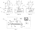
- the typical printing (front) side of a photopolymer printing plate 10 comprises a dimensionally stable layer 12 covered with photopolymer 14.
- Suitable materials for the dimensionally stable layer and photopolymer are well known in the art, including configurations for applying a liquid photopolymer to the dimensionally stable layer immediately prior to imaging, as described further herein.
- the photopolymer layer 14 may have one or more substantially transparent film layers thereover, not shown, particularly in liquid photopolymer embodiments.
- the shape of the cured portions of photopolymer 16A, 16B, 16C formed by the curing beam 20 can be varied by the beam diameter D and the distance d between the focusing optics 30 (e.g.
- a lens and the photopolymer to be cured.
- Using a relatively smaller beam diameter will make the socket of the pixel smaller and steeper, whereas using a relatively bigger beam diameter will make the socket broader.
- D 1 of Fig. 1A as compared to D 2 of Fig. 1B , creates a conical shape of cured polymer 16A that has a relatively smaller volume than that of cured polymer 16B, and has an angle ⁇ 1 that is relatively larger than angle ⁇ 2 .
- positioning the lens 30 at a relatively smaller distance d 2 as compared to d 1 from the surface of the photopolymer also moves the focal spot closer to the surface of the polymer (e.g. distance f 2 is relatively shorter than f 1 ), and the resulting cured polymer 16B has a greater volume than 16C, at the same angle ⁇ 2 , because the truncated portion of the cone cured into the polymer starts at a relatively greater diameter cross-section of the cone at the surface of the polymer and extends to a relatively larger diameter cross-section of the cone at the base.
- the profile of the conical shape can be adjusted by the caustic of the laser beam propagation, and depending on the combination of beam diameter D and focal offset f, at a given focal length of the focus lens, the support shoulders may thus be made broader or steeper.
- the focus spot size of the laser beam may be too small for the pixel size to be cured. Therefore, defocussing the beam by moving the focal point further away from the plate surface also adjusts the beam diameter at the plate surface to the diameter required by the image resolution.
- the plate surface may be structured to improve ink transfer properties of the plate in the press.
- Methods of structuring the plate surface for improved ink transfer have been known for years. Some such methods use mechanical structuring similar to embossing after imaging, curing and removal of non-cured portions of the plate to provide structure to the plate surface, such as is described in WO2015007667A1 .
- Structural properties preferably are defined to match ink properties and press conditions, and thus some effort is typically made to adjust the shape of the structures.
- the structure may be created by perforating the mask with individual laser pulses, with a control mechanism adjusting the mask opening size via the laser pulse energy.
- the mask opening size is replaced by the size of the curing beam, which may be simply adjusted by modulating the distance between the focus lens and the polymer plate surface. Moving the focus closer to the plate surface will make the size of the cured details smaller; moving the focus further away will make the size bigger.
- the beam of radiation is preferably split into several beams using an Acousto Optical Deflector.
- a suitable deflector may be, for example, a model D1370-aQ120-9 from ISOMET.
- the beams are preferably oriented to be disposed an equal distance in the advance direction of the Imager, whereas the beam distance corresponds to the image resolution that shall be cured into the plate. Distributing the laser beam into several individual beams not only increases productivity, but also reduces the risk of the polymer being damaged by the high intensity of the laser beam.
- One method to check the focus position may comprise fixing a stripe of tape, such as 3M ® Temflex ® 1500 tape, on top of the polymer plate. UV light is absorbed by the tape, producing a detectable pattern having a size from which the focus distance can be derived, and the right focus spot size can then be determined on top of the tape and the working position for the focus on the polymer plate can adjusted by subtracting the thickness of the tape.
- the focus position can be determined by engraving several tracks in the tape or on a test plate at different focus distances and identifying the track with the desired track width.
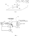
- one aspect of the invention comprises an imager 200 for applying high resolution image information 202 into a photopolymer printing plate 204 having a printing area 206 on its front surface 208, and a back surface 210 opposite the front surface.
- the term "high resolution image information” refers to image information typically used in flexographic printing, including image information with and without individual structures defined within the printing dots.
- Front side radiation source 220 is configured to emit radiation 222 suitable for curing the printing plate photopolymer.
- printing plate 204 is mounted in an imaging location 224 positioned at a predetermined distance H from radiation source 220, with front surface 208 facing the radiation source.
- a control system 250 directs relative motion between the radiation source and the plate and modulates the radiation in a pattern corresponding to the image information 202, so that all portions of the plate in the printing area corresponding to pixels intended to transfer ink the image information are sufficiently cured to proceed to later processing of the plate.
- the image information 202 is typically provided from a computer memory 260 in a format readable by the controller.
- the memory may reside on the imager, or may reside remotely from the imager, with a signal provided to the controller that is readable or translatable by the controller into instructions for moving and modulating the radiation source.
- Modulator 230 is configured to modulate the radiation directed from the radiation source. Although depicted as part of source 220 in Fig. 2 , the modulator may be a distinct and discrete component in optical communication with the source but not integrally a part of the source. As noted above, the modulator may comprise an Acousto Optical Modulator and a deflector operable to split the radiation source into two or more beams. Details of suitable modulators are further described in U.S. Patent Application Ser. No. US20140327185 , granted to the same inventor of the present application.
- the invention is not limited to any particular modulator or deflector arrangement, however, and may comprise any system operable to impart radiation to a plate of intensity and resolution to directly cure the photopolymer on the plate in the desired pattern.
- the control system 250 typically comprises a scanner mechanism, such as mechanisms well known in the art in imaging technology, typically provides relative motion between the radiation source and the front surface of the printing plate such that all of the printing area is exposed to the modulated radiation.
- a flatbed arrangement scanner mechanism 300 is configured to move light source 302 along the X and Y axes relative to the plate 304 in a rastering fashion, or in another variation, radiation source 302 may move along the X axis and plate 304 may move along the Y axis.
- the light source may comprise a plurality of (e.g.
- LED LED
- Fiber laser light sources typically operate in a rastering manner only.
- Such mechanisms are well known in the art, and typically comprise at least one or more drive mechanisms 310 configured to move the radiation source and/or the plate, connected to a controller 320 that controls the movements of the one or more drive mechanisms, and a power source 330.
- the scanner mechanism may comprise a drum exposure arrangement, as shown in Fig. 4 .
- the scanner mechanism comprises a drive mechanism 410 (such as a motor and a transmission system, including gearing, belt drives, or the like) that rotates drum 402 in a transverse, circumferential direction about an axis of rotation and that advances a carriage 404, on which is mounted the radiation source and associated optics, in a longitudinal (axial) direction parallel to the drum rotation axis, controlled by control system 420 and powered by power supply 430.
- Printing plate 406 in a drum configuration may be in the form of a sleeve, or may be rectangular sheet, with the drum configured to hold opposite edges of the sheet in place with any one of various clamping systems known in the art, while the drum rotates.
- the imager may also have a back side radiation source facing the back side of the printing plate and positioned to provide an exposure to the back side along a processing path of the plate.
- plate 204 may move along a processing path defining a sequential path of travel for the plate in a workflow extending between a first location A anterior to the imaging position and a second location P posterior to the imaging location.
- Back side radiation source 270 shown in location B, may provide, for example, a line exposure to the back side as the plate moves over top of it.
- back side radiation source 270 may be located in position A, or anywhere in the workflow between A and B, including in the imaging location 224, where the imaging location comprises a stage that is sufficiently transparent to the radiation to permit exposure, such as if the imaging location comprises exposure glass or other type of transparent plate.
- the back side radiation source may be a bank exposure that exposes the entire back side at one time, a line source as shown in Fig. 2 , or a rastering source.
- back side radiation source may be coordinated with the front side exposure so that the back side radiation precedes the front side radiation by an amount of time that is predetermined to maximize the final plate characteristics, such as is described in Published PCT Patent App. No. WO2017/072588 , listing a common co-inventor with the present application.
- the drum may be transparent and the back side radiation source may be located inside the drum, or the back side radiation source may be located along a process path through which the plate follows before being mounted on or after being dismounted from the drum.
- One advantage of embodiments of the invention described herein is that printing plates without a LAMs layer may be used, thereby avoiding all of the complications created by the need for a LAMs layer, as described herein above..
- the process may include a first step of placing a photopolymer printing plate in an imaging location at a predetermined distance from a radiation source, with the front (printing) surface facing the radiation source.
- the printing plate preferably comprises a photopolymer printing plate having a printing area on a front surface, without a LAMs layer.
- the radiation source may be any source suitable for curing the printing plate photopolymer.
- the process comprises modulating the radiation from the radiation source while providing relative motion between the front surface of the printing plate and the radiation source sufficient to expose all of the printing area to modulated radiation in a pattern corresponding to the high resolution imaging information desired to transferred to the plate.
- the process comprises focusing the modulated radiation onto a focal spot located a distance above the printing surface such that the modulated radiation propagates from the focal spot toward the plate in a beam having a conical shape suitable to create a cured profile in the polymer material that defines conically shaped support shoulders in printing features resulting from further processing of the printing plate.
- the conical shape of the support shoulders is determined by the optical shape of a beam, with the tip of the optical shape having a size determined by the distance between the focal spot and the surface of the polymer material.
- the process may further comprise the step of exposing a back side of the printing plate opposite the front side to radiation along a processing path of the plate extending from prior to placing the plate in the imaging location to after placing the plate in the imaging location.
- the photopolymer printing plate comprises a sleeve
- the step of placing the plate in the imaging location comprises placing the plate on a drum
- the step of providing the relative motion comprises rotating the drum.
- direct curing also permits use of liquid photopolymer applied to the plate prior to imaging.
- the process may comprising applying a liquid photopolymer to a flat dimensionally stable support layer of the plate prior to the imaging the printing plate and prior to back exposure.
- Application of liquid photopolymer minimizes handling damage to the plate prior to imaging as compared to the use of solid photopolymer plates, permits reclaiming unexposed polymer, and reduces plate cost, overall.
- Creating printing plates using liquid polymer generally, are well known and available in the art, with one exemplary and non-limiting embodiment described in U.S. Published Patent App. No. US20110300398 and US2016/0311214 .
- photomask generally refers to any type of film negative or other layer comprising image information as is known in prior art processes for imparting the image information to the plate.
- An exemplary process using a liquid photopolymer in connection may include the steps of a) placing a substantially transparent dimensionally stable layer onto an exposure glass, b) casting a liquid photopolymerizable resin layer onto the dimensionally stable layer; c) laminating a coverfilm to a surface of the liquid photopolymerizable resin layer that is opposite to the dimensionally stable layer as the liquid photopolymerizable resin layer is being cast onto the dimensionally stable layer; d) exposing the liquid photopolymerizable resin layer through the exposure glass and dimensionally stable layer to selectively crosslink and cure the photopolymerizable resin layer at a depth less than the height of the cast liquid photopolymerizable resin, to attach the polymer resin to the dimensionally stable layer, and e) directly exposing the opposite side of the photopolymerizable resin to the modulated radiation through the coverfilm in a pattern corresponding to a high resolution image, per the processes described herein.
- steps for finishing the plate may comprise, reclaiming the unexposed polymer from the plate, removing the coverfilm, washing, rinsing, and finishing (fixing) the plate, all steps that are well known in the art.
- the dimensionally stable layer and the coverfilm may comprise a single layer each, or may comprise multilayer composites, and additional layers or coatings may be disposed under or over each layer, to impart desired functionality.
- the invention is not limited to any particular structure comprising the liquid polymer, nor is it limited to any particular type of liquid polymer. Suitable liquid polymers are well known in the art, including but not limited to, AVantage ® liquid photopolymers marketed by Anderson & Vreeland or Bryan, Ohio, United States.
- the present invention permits use of a single apparatus for applying liquid photopolymer and directly exposing the plate, including a spool for holding a roll of coverfilm to be spread across the exposure glass, a first carriage for simultaneously applying the photopolymerizable resin layer onto the dimensionally stable layer along with the coverfilm, a back exposure unit disposed underneath the exposure glass, and a second carriage for scanning the radiation source across the photopolymer in the X and Y directions.
- the footprint for travel of the first carriage may be nested inside the footprint of the second carriage so that the first carriage can traverse the plate from one end to the other without interfering with the second carriage in a non-use position.
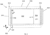
- FIG. 5 depicts a plan view of an exemplary exposure system 500 comprising exposure glass 502, over which the dimensionally stable layer 504 is then disposed by dispensing it from a roll 506 of material along arrow A, and cutting it to cover the exposure glass.
- the term "glass” with reference to the exposure glass may comprise any materials, including various plastics and resinous materials, suitable for providing the durability, transparency, and rigidity required for the subject application, and is not limited to “glass” per se.
- transparent as used herein, means sufficiently translucent to provide a level of exposure desired on the backside of the plate, once formed.
- polymer application carriage 510 traverses the exposure glass along the X direction along arrow B from a storage position 512 to a starting position 514, and then dispenses the liquid photopolymer and coverfilm from the carriage, while the carriage traverses back to the storage position in the direction of arrow C, as is known in the art.
- the envelope of travel of carriage 510 is outlined by box 516 marked by a first style of dashed lines.
- a backside exposure may be provided from underneath exposure glass 502, to fix the photopolymer to the dimensionally stable layer.
- the radiation source and imaging optics 520 scans the plate along the X and Y direction in a rastering fashion along the path of arrows D starting from a storage position 522, moving within the envelope defined by box 524, marked by dashed lines different than those of box 516, in accordance with instructions provided by its control mechanism. In this way, the high resolution image is directly cured into the front side of the plate.
- the second carriage may be located on the other side of class 502, in which case it does not interfere with the envelope of movement of carriage 510.
- a non-reflective cover (not shown) may be closed over the plate during the back exposure step, or a non-reflective shutter disposed under the exposure glass during the front side exposure step in the arrangement shown.
- a cover may be provided with a bank back-side exposure source for effective that step.
- exemplary storage positions 512 and 522, and envelopes of travel 516 and 524, for the polymer application carriage and imaging carriage, respectively it should be understood that the storage locations and envelopes may have any location and shape, respectively, so long as both carriages are sufficiently able to traverse the entirety of the portion of the plate desired to be covered without interfering with the other in its storage position.
Landscapes
- Physics & Mathematics (AREA)
- General Physics & Mathematics (AREA)
- Optics & Photonics (AREA)
- Manufacture Or Reproduction Of Printing Formes (AREA)
- Exposure And Positioning Against Photoresist Photosensitive Materials (AREA)
Claims (15)
- Ein Bildgeber (200) zum Anwenden von hochauflösender Bildinformation (202) in eine Photopolymer-Druckplatte (204), die einen Druckbereich (206) auf einer Frontoberfläche (208) davon und einer Rückoberfläche (210) gegenüber der Frontoberfläche aufweist, wobei der Bildgeber (200) Folgendes umfasst:eine frontseitige Strahlungsquelle (220), die so konfiguriert ist, dass sie Strahlung emittiert, die zum Härten der Photopolymer-Druckplatte (204) geeignet ist;eine Bebilderungsstelle (224), um die Druckplatte (204) in einem vorbestimmten Abstand (H) von der frontseitigen Strahlungsquelle (220) zu montieren, wobei die Frontoberfläche (208) der frontseitigen Strahlungsquelle (220) zugewandt ist;einen Modulator (230), der zwischen der frontseitigen Strahlungsquelle (220) und der Frontoberfläche (208) der Druckplatte (204) angeordnet ist, wobei der Modulator (230) so konfiguriert ist, dass er die von der frontseitigen Strahlungsquelle (220) auf die Frontoberfläche (208) gerichtete Strahlung moduliert;einen Scannermechanismus (300) zum Bereitstellen einer relativen Bewegung zwischen der Frontoberfläche (208) der Druckplatte (204) und der frontseitigen Strahlungsquelle (220), wobei der Scannermechanismus (300) betreibbar ist, um den gesamten Druckbereich (206) mit modulierter Strahlung abzudecken;eine Steuerung (250), die mit dem Modulator (230) und dem Scannermechanismus (300) verbunden und so konfiguriert ist, dass sie Steuersignale für den Modulator (230) und den Scannermechanismus (300) bereitstellt, die so betreibbar sind, dass die Frontoberfläche (208) der Druckplatte (204) mit der modulierten Strahlung entsprechend der hochauflösenden Bildinformation belichtet wird; undeine Optik (30), die so konfiguriert ist, dass sie die modulierte Strahlung auf einen Brennfleck fokussiert,wobei der Bildgeber so konfiguriert ist, dass er die Druckplatte (204) bebildert (to image), indem er den Brennfleck in einem Abstand über der Frontoberfläche (208) anordnet, sodass sich die modulierte Strahlung vom Brennfleck in Richtung der Druckplatte (204) in einem Strahl ausbreitet, der eine konische Form aufweist, die geeignet ist, im Polymermaterial ein gehärtetes Profil zu erzeugen, das konisch geformte Trägerschultern in Druckmerkmalen definiert, die sich aus der weiteren Verarbeitung der Druckplatte ergeben.
- Der Bildgeber (200) nach Anspruch 1, der ferner eine rückseitige Strahlungsquelle (270) umfasst, die der Rückoberfläche (210) der Druckplatte (204) zugewandt ist und so positioniert ist, dass sie eine Belichtung der Rückoberfläche (210) entlang eines Bearbeitungspfads der Druckplatte (204) ermöglicht, und wobei optional der Bearbeitungspfad einen sequentiellen Bewegungspfad für die Druckplatte (204) in einem Arbeitsfluss definiert, der sich zwischen einer ersten Stelle vor der Bebilderungsstelle und einer zweiten Stelle hinter der Bebilderungsstelle erstreckt.
- Der Bildgeber (200) nach Anspruch 1 oder 2, wobei die frontseitige Strahlungsquelle einen Laser oder eine LED umfasst.
- Der Bildgeber (200) nach irgendeinem der Ansprüche von 1 bis 3, wobei der Modulator einen akusto-optischen Modulator umfasst; und/oder
wobei der Modulator einen Deflektor umfasst, der so betrieben werden kann, dass er die Strahlung der frontseitigen Strahlungsquelle (220) in zwei oder mehr Strahlen aufteilt. - Der Bildgeber (200) nach irgendeinem der Ansprüche von 1 bis 4, wobei die Photopolymer-Druckplatte (204) eine Hülle umfasst, die Bebilderungsstelle eine Trommel umfasst und der Scannermechanismus einen Motor zum Drehen der Trommel entlang einer Trommeldrehachse und einen Schlitten zum Bewegen der Strahlungsquelle parallel zur Trommeldrehachse umfasst.
- Der Bildgeber (200) nach irgendeinem der Ansprüche von 1 bis 5, der ferner Folgendes umfasst:ein Belichtungsglas zur Aufnahme der Platte an der Bebilderungsstelle, wobei eine erste Strahlungsquelle so positioniert ist, dass sie eine erste Seite der Platte durch das Belichtungsglas belichtet;einen Halter in der Nähe der Bebilderungsstelle, der so konfiguriert ist, dass er eine Rolle eines ersten Films über der Bebilderungsstelle hält und ausgibt;einen Schlitten, der so konfiguriert ist, dass er flüssiges Photopolymer auf den ersten Film aufträgt und einen zweiten Film über das flüssige Photopolymer aufträgt; undeine zweite Strahlungsquelle, die konfiguriert ist, um eine zweite Seite der Platte zu belichten.
- Der Bildgeber (200) nach Anspruch 6, wobei die erste Seite der Platte eine Rückseite der Platte ist, die erste Strahlungsquelle eine rückseitige Strahlungsquelle ist, der erste Film eine dimensionsstabile Schicht der Druckplatte umfasst, und die zweite Strahlungsquelle die frontseitige Strahlungsquelle umfasst; oder
wobei die erste Seite der Platte eine Vorderseite der Platte ist, die erste Strahlungsquelle die frontseitige Strahlungsquelle ist, der zweite Film eine dimensionsstabile Schicht der Druckplatte umfasst, und die zweite Strahlungsquelle eine rückseitige Strahlungsquelle umfasst. - Ein Bildgebungssystem, das Folgendes umfasst:den Bildgeber nach irgendeinem der Ansprüche von 1 bis 7;einen Speicher, der mit der Steuerung in Verbindung steht, wobei der Speicher so konfiguriert ist, dass er Daten speichert, die den hochauflösenden Bildinformationen entsprechen.
- Das Bildgebungssystem nach Anspruch 8, das ferner die Photopolymer-Druckplatte (204) umfasst, wobei die Druckplatte eine Flexodruckplatte umfasst, und wobei die Druckplatte optional keine laserabtragbare Masken- oder Fotomasken-Schicht aufweist.
- Ein Verfahren zur Bebilderung (imaging) einer Druckplatte (204), wobei das Verfahren die folgenden Schritte umfasst:(a) Platzieren einer Photopolymer-Druckplatte (204) an eine Bebilderungsstelle (224) in einem vorbestimmten Abstand von einer Strahlungsquelle (220); wobei die Druckplatte (204) eine Photopolymer-Druckplatte mit einem Druckbereich (206) auf ihrer Frontoberfläche (208) umfasst, wobei die Strahlungsquelle (220) zum Aushärten der Photopolymer-Druckplatte (204) geeignet ist, wobei die Druckplatte (204) an der Bebilderungsstelle (224) so angeordnet ist, dass ihre Frontoberfläche (208) der Strahlungsquelle (229) zugewandt ist;(b) Modulieren der Strahlung aus der Strahlungsquelle (220), während eine Relativbewegung zwischen der Frontoberfläche (208) der Druckplatte (204) und der Strahlungsquelle (220) bereitgestellt wird, die ausreicht, um den gesamten Druckbereich mit modulierter Strahlung in einem Muster zu belichten, das hochauflösender Bildinformation entspricht; undFokussieren der modulierten Strahlung auf einen Brennfleck, der sich in einem Abstand oberhalb einer Druckfläche befindet, sodass sich die modulierte Strahlung vom Brennfleck in Richtung der Druckplatte (204) in einem Strahl mit einer konischen Form ausbreitet, die dazu geeignet ist, ein gehärtetes Profil im Polymermaterial zu erzeugen, der konisch geformte Stützschultern in Druckmerkmalen definiert, die sich aus der weiteren Verarbeitung der Druckplatte ergeben.
- Das Verfahren nach Anspruch 10, wobei die konische Form der Stützschultern durch den Durchmesser des Strahls und die Brennweite einer Fokussiereinrichtung bestimmt wird, wobei vorzugsweise die konische Form eine Spitze mit einer Spitzengröße aufweist, die durch den Abstand zwischen dem Brennfleck und der Oberfläche des Polymermaterials bestimmt wird.
- Das Verfahren nach Anspruch 10 oder 11, das ferner den Schritt umfasst, eine der Frontoberfläche (208) gegenüberliegende Rückoberfläche (210) der Druckplatte (204) entlang eines Bearbeitungspfads der Druckplatte (204) einer Strahlung auszusetzen, der sich von vor dem Einsetzen der Platte in die Bebilderungsstelle bis nach dem Einsetzen der Platte in die Bebilderungsstelle erstreckt; und/oder
wobei der Schritt des Modulierens das Aufspalten der Strahlung in zwei oder mehr Strahlen umfasst. - Das Verfahren nach irgendeinem der Ansprüche von 10 bis 12, wobei die Photopolymer-Druckplatte eine Flexodruckplatte umfasst, und wobei vorzugsweise die Druckplatte keine laserabtragbare Masken- oder Fotomasken-Schicht aufweist.
- Das Verfahren nach irgendeinem der Ansprüche von 10 bis 13, wobei die Photopolymer-Druckplatte eine Hülle umfasst, der Schritt des Platzierens der Platte an der Bebilderungsstelle das Platzieren der Platte auf einer Trommel umfasst, und der Schritt des Bereitstellens der Relativbewegung das Drehen der Trommel und das Bewegen der Strahlungsquelle parallel zur Trommeldrehachse umfasst.
- Das Verfahren nach irgendeinem der Ansprüche von 10 bis 13, das ferner den Schritt umfasst, vor der Belichtung der Druckplatte, ein flüssiges Photopolymer auf ein Substrat aufzutragen, um die Photopolymer-Druckplatte zu bilden; und wobei optional Schritt (a) das Anordnen eines ersten Films über der Bebilderungsstelle umfasst, wobei die genannte Bebilderungsstelle ein Belichtungsglas umfasst, dann das Auftragen des flüssigen Polymers und eines zweiten Films über das flüssige Polymer, dann das Belichten einer Rückseite der Platte, um das flüssige Polymer an einem der Filme eins oder zwei haften zu lassen, und dann das Durchführen von Schritt (b) an einer Vorderseite der Platte.
Priority Applications (1)
| Application Number | Priority Date | Filing Date | Title |
|---|---|---|---|
| EP20213034.0A EP3812840A1 (de) | 2017-07-20 | 2018-07-20 | System und verfahren zur direkten härtung von photopolymerdruckplatten |
Applications Claiming Priority (2)
| Application Number | Priority Date | Filing Date | Title |
|---|---|---|---|
| US201762534962P | 2017-07-20 | 2017-07-20 | |
| PCT/EP2018/069780 WO2019016376A1 (en) | 2017-07-20 | 2018-07-20 | SYSTEM AND METHOD FOR DIRECT CURING OF PHOTOPOLYMER PRINTING PLATES |
Related Child Applications (2)
| Application Number | Title | Priority Date | Filing Date |
|---|---|---|---|
| EP20213034.0A Division-Into EP3812840A1 (de) | 2017-07-20 | 2018-07-20 | System und verfahren zur direkten härtung von photopolymerdruckplatten |
| EP20213034.0A Division EP3812840A1 (de) | 2017-07-20 | 2018-07-20 | System und verfahren zur direkten härtung von photopolymerdruckplatten |
Publications (2)
| Publication Number | Publication Date |
|---|---|
| EP3655822A1 EP3655822A1 (de) | 2020-05-27 |
| EP3655822B1 true EP3655822B1 (de) | 2022-06-22 |
Family
ID=63113483
Family Applications (2)
| Application Number | Title | Priority Date | Filing Date |
|---|---|---|---|
| EP20213034.0A Pending EP3812840A1 (de) | 2017-07-20 | 2018-07-20 | System und verfahren zur direkten härtung von photopolymerdruckplatten |
| EP18750354.5A Active EP3655822B1 (de) | 2017-07-20 | 2018-07-20 | System und verfahren zur direkten härtung von photopolymerdruckplatten |
Family Applications Before (1)
| Application Number | Title | Priority Date | Filing Date |
|---|---|---|---|
| EP20213034.0A Pending EP3812840A1 (de) | 2017-07-20 | 2018-07-20 | System und verfahren zur direkten härtung von photopolymerdruckplatten |
Country Status (5)
| Country | Link |
|---|---|
| US (2) | US10831105B2 (de) |
| EP (2) | EP3812840A1 (de) |
| CN (1) | CN110892334B (de) |
| DE (1) | DE20213034T1 (de) |
| WO (1) | WO2019016376A1 (de) |
Families Citing this family (2)
| Publication number | Priority date | Publication date | Assignee | Title |
|---|---|---|---|---|
| US10732507B2 (en) | 2015-10-26 | 2020-08-04 | Esko-Graphics Imaging Gmbh | Process and apparatus for controlled exposure of flexographic printing plates and adjusting the floor thereof |
| DE20213034T1 (de) | 2017-07-20 | 2021-06-24 | Esko-Graphics Imaging Gmbh | System und verfahren zur direkten härtung von photopolymerdruckplatten |
Family Cites Families (23)
| Publication number | Priority date | Publication date | Assignee | Title |
|---|---|---|---|---|
| US6266134B1 (en) * | 1998-01-20 | 2001-07-24 | Creo Products Inc. | System for exposing photopolymer with light from compact movable light source |
| US6767685B2 (en) * | 1999-12-03 | 2004-07-27 | Fuji Photo Film Co., Ltd. | Plate-making method, plate-making apparatus used in such plate-making method, and image recording material |
| DE10024456A1 (de) | 2000-05-18 | 2001-11-29 | Heidelberger Druckmasch Ag | Integrierte Laser- und UV-Belichtung von Druckplatten |
| JP2002307645A (ja) * | 2001-04-16 | 2002-10-23 | Fuji Photo Film Co Ltd | 光走査画像記録装置 |
| US6976426B2 (en) * | 2002-04-09 | 2005-12-20 | Day International, Inc. | Image replication element and method and system for producing the same |
| US20090101845A1 (en) | 2005-04-02 | 2009-04-23 | Punch Graphix Prepress Germany Gmbh | Exposure Device for Printing Plates |
| DE102005031057A1 (de) | 2005-07-02 | 2007-01-04 | Punch Graphix Prepress Germany Gmbh | Verfahren zur Belichtung von Flexodruckplatten |
| US8516961B2 (en) | 2007-05-08 | 2013-08-27 | Esko-Graphics Imaging Gmbh | Method and apparatus for loading and unloading flexographic plates for computer-to-plate imaging including separate loading and unloading areas |
| US8227769B2 (en) * | 2008-05-27 | 2012-07-24 | Esko-Graphics Imaging Gmbh | Curing of photo-curable printing plates with flat tops or round tops |
| US8034540B2 (en) * | 2008-07-31 | 2011-10-11 | Eastman Kodak Company | System and method employing secondary back exposure of flexographic plate |
| US8476000B2 (en) | 2010-06-04 | 2013-07-02 | Ryan Vest | Method of producing a relief image from a liquid photopolymer resin |
| EP2466381B1 (de) | 2010-12-16 | 2021-05-19 | Xeikon Prepress N.V. | Verarbeitungsvorrichtung zum Verarbeiten einer flexografischen Platte, Verfahren und Computerprogrammprodukt |
| EP2738606B1 (de) | 2012-11-28 | 2024-01-31 | XSYS Prepress N.V. | Verfahren und Computerprogrammprodukt zum Verarbeiten einer flexografischen Platte. |
| EP2778784B8 (de) | 2013-03-11 | 2022-02-23 | Esko-Graphics Imaging GmbH | Vorrichtung und Verfahren zur direkten Mehrstrahlengravur elastomerer Druckplatten und -hülsen |
| GB201312450D0 (en) | 2013-07-11 | 2013-08-28 | Rainbow Technology Systems Ltd | Direct Imaging of a Sealed Wet Photopolymer Pouch |
| US9671695B2 (en) | 2013-07-15 | 2017-06-06 | Flint Group Germany Gmbh | Process of manufacturing flexographic printing forms |
| WO2016052494A1 (ja) | 2014-09-30 | 2016-04-07 | 富士フイルム株式会社 | フレキソ印刷版の製造方法 |
| US9703201B2 (en) | 2015-04-22 | 2017-07-11 | Macdermid Printing Solutions, Llc | Method of making relief image printing plates |
| EP3879344A1 (de) | 2015-10-26 | 2021-09-15 | Esko-Graphics Imaging GmbH | System und verfahren zur gesteuerten belichtung von flexodruckplatten |
| US9740103B2 (en) * | 2015-11-09 | 2017-08-22 | Macdermid Printing Solutions, Llc | Method and apparatus for producing liquid flexographic printing plates |
| EP3984761B1 (de) | 2016-05-27 | 2025-10-15 | Esko Software BV | Verfahren für glattere tonale reaktion beim flexodruck |
| DE20213034T1 (de) * | 2017-07-20 | 2021-06-24 | Esko-Graphics Imaging Gmbh | System und verfahren zur direkten härtung von photopolymerdruckplatten |
| BR112020023588A2 (pt) | 2018-05-18 | 2021-02-09 | F. Hoffmann-La Roche Ag | método para a produção de brometo de b-d-ribofuranosídeo de nicotinamida cristalino de fórmula o-ia, método, para a produção de sais de ¿-d-ribofuranosídeo de (tio)nicotinamida cristalinos, método para a produção de uma composição compreendendo um sal amorfo de ¿-d-ribofuranosídeo de (tio)nicotinamida, brometo de 2,3,5-tri-o-acetil-¿-d-ribofuranosídeo de nicotinamida cristalino de fórmula o-va, brometo de ¿-d-ribofuranosídeo de nicotinamida ou de tionicotinamida cristalino de fórmulas o-ia e s-ia, composição, uso de um composto ¿-d-ribofuranosídeo de (tio)nicotinamida cristalino, composição farmacêutica, método para a produção de brometo de tri-o-acil-¿-d-ribofuranosídeo de fórmula iii, método para remoção de grupos acila de brometo de 2,3,5-tri-o-acil-¿-d-ribofuranosídeo de nicotinamida de fórmula o-va ou de cloreto de 2,3,5-tri-o-acil-¿-d-ribofuranosídeo de nicotinamida de fórmula o-vb |
-
2018
- 2018-07-20 DE DE20213034.0T patent/DE20213034T1/de active Pending
- 2018-07-20 EP EP20213034.0A patent/EP3812840A1/de active Pending
- 2018-07-20 CN CN201880048501.3A patent/CN110892334B/zh active Active
- 2018-07-20 EP EP18750354.5A patent/EP3655822B1/de active Active
- 2018-07-20 US US16/629,061 patent/US10831105B2/en active Active
- 2018-07-20 WO PCT/EP2018/069780 patent/WO2019016376A1/en not_active Ceased
-
2020
- 2020-10-09 US US17/066,698 patent/US11314170B2/en active Active
Also Published As
| Publication number | Publication date |
|---|---|
| US10831105B2 (en) | 2020-11-10 |
| US11314170B2 (en) | 2022-04-26 |
| DE20213034T1 (de) | 2021-06-24 |
| EP3812840A1 (de) | 2021-04-28 |
| CN110892334B (zh) | 2022-12-09 |
| US20210026247A1 (en) | 2021-01-28 |
| EP3655822A1 (de) | 2020-05-27 |
| WO2019016376A1 (en) | 2019-01-24 |
| US20200133129A1 (en) | 2020-04-30 |
| CN110892334A (zh) | 2020-03-17 |
Similar Documents
| Publication | Publication Date | Title |
|---|---|---|
| US5654125A (en) | Laser apparatus and process of use | |
| US7807001B2 (en) | Lamination device method for flexographic plate manufacturing | |
| US20010052924A1 (en) | Method and device for integrated laser and UV exposure of printing plates | |
| US6630286B2 (en) | Process for preparing a printing plate | |
| EP2002306B1 (de) | Verfahren zur herstellung einer flexodruckplattenanordnung | |
| US11314170B2 (en) | System and process for direct curing of photopolymer printing plates | |
| EP3794411B1 (de) | Verfahren und vorrichtung zur automatischen dichtemessung von fotopolymerdruckplatten | |
| JP3226552B2 (ja) | オフセット印刷版の製造方法 | |
| JP3524909B2 (ja) | レーザグラビアによるフィルム又は印刷版のアブレーション方法及びマルチビーム走査装置 | |
| EP1674931B1 (de) | Belichtungssystem und Verfahren zur Herstellung von Druckformen | |
| EP2738606B1 (de) | Verfahren und Computerprogrammprodukt zum Verarbeiten einer flexografischen Platte. | |
| JP4396979B2 (ja) | レーザ露光装置 | |
| EP2778784B1 (de) | Vorrichtung und Verfahren zur direkten Mehrstrahlengravur elastomerer Druckplatten und -hülsen | |
| US20020135745A1 (en) | Multibeam scanning device for scanning a photosensitive material with a multi-spot array, and method of correcting the position of image points of the multi-spot array | |
| US8963971B2 (en) | Laser exposure method and product | |
| US20250244674A1 (en) | Method for imaging a mask layer and associated imaging system | |
| NL2034371B1 (en) | Methods and systems for imaging a mask layer | |
| JP2001166467A (ja) | 製版方法及び製版装置 | |
| JP2007030497A (ja) | 光源ユニット、画像形成装置および印刷装置 |
Legal Events
| Date | Code | Title | Description |
|---|---|---|---|
| STAA | Information on the status of an ep patent application or granted ep patent |
Free format text: STATUS: UNKNOWN |
|
| STAA | Information on the status of an ep patent application or granted ep patent |
Free format text: STATUS: THE INTERNATIONAL PUBLICATION HAS BEEN MADE |
|
| PUAI | Public reference made under article 153(3) epc to a published international application that has entered the european phase |
Free format text: ORIGINAL CODE: 0009012 |
|
| STAA | Information on the status of an ep patent application or granted ep patent |
Free format text: STATUS: REQUEST FOR EXAMINATION WAS MADE |
|
| 17P | Request for examination filed |
Effective date: 20200213 |
|
| AK | Designated contracting states |
Kind code of ref document: A1 Designated state(s): AL AT BE BG CH CY CZ DE DK EE ES FI FR GB GR HR HU IE IS IT LI LT LU LV MC MK MT NL NO PL PT RO RS SE SI SK SM TR |
|
| AX | Request for extension of the european patent |
Extension state: BA ME |
|
| DAV | Request for validation of the european patent (deleted) | ||
| DAX | Request for extension of the european patent (deleted) | ||
| STAA | Information on the status of an ep patent application or granted ep patent |
Free format text: STATUS: EXAMINATION IS IN PROGRESS |
|
| 17Q | First examination report despatched |
Effective date: 20210625 |
|
| GRAP | Despatch of communication of intention to grant a patent |
Free format text: ORIGINAL CODE: EPIDOSNIGR1 |
|
| STAA | Information on the status of an ep patent application or granted ep patent |
Free format text: STATUS: GRANT OF PATENT IS INTENDED |
|
| INTG | Intention to grant announced |
Effective date: 20220128 |
|
| GRAS | Grant fee paid |
Free format text: ORIGINAL CODE: EPIDOSNIGR3 |
|
| GRAA | (expected) grant |
Free format text: ORIGINAL CODE: 0009210 |
|
| STAA | Information on the status of an ep patent application or granted ep patent |
Free format text: STATUS: THE PATENT HAS BEEN GRANTED |
|
| AK | Designated contracting states |
Kind code of ref document: B1 Designated state(s): AL AT BE BG CH CY CZ DE DK EE ES FI FR GB GR HR HU IE IS IT LI LT LU LV MC MK MT NL NO PL PT RO RS SE SI SK SM TR |
|
| REG | Reference to a national code |
Ref country code: GB Ref legal event code: FG4D |
|
| REG | Reference to a national code |
Ref country code: CH Ref legal event code: EP |
|
| REG | Reference to a national code |
Ref country code: DE Ref legal event code: R096 Ref document number: 602018037032 Country of ref document: DE |
|
| REG | Reference to a national code |
Ref country code: AT Ref legal event code: REF Ref document number: 1500150 Country of ref document: AT Kind code of ref document: T Effective date: 20220715 |
|
| REG | Reference to a national code |
Ref country code: IE Ref legal event code: FG4D |
|
| REG | Reference to a national code |
Ref country code: LT Ref legal event code: MG9D |
|
| REG | Reference to a national code |
Ref country code: NL Ref legal event code: MP Effective date: 20220622 |
|
| PG25 | Lapsed in a contracting state [announced via postgrant information from national office to epo] |
Ref country code: SE Free format text: LAPSE BECAUSE OF FAILURE TO SUBMIT A TRANSLATION OF THE DESCRIPTION OR TO PAY THE FEE WITHIN THE PRESCRIBED TIME-LIMIT Effective date: 20220622 Ref country code: NO Free format text: LAPSE BECAUSE OF FAILURE TO SUBMIT A TRANSLATION OF THE DESCRIPTION OR TO PAY THE FEE WITHIN THE PRESCRIBED TIME-LIMIT Effective date: 20220922 Ref country code: LT Free format text: LAPSE BECAUSE OF FAILURE TO SUBMIT A TRANSLATION OF THE DESCRIPTION OR TO PAY THE FEE WITHIN THE PRESCRIBED TIME-LIMIT Effective date: 20220622 Ref country code: HR Free format text: LAPSE BECAUSE OF FAILURE TO SUBMIT A TRANSLATION OF THE DESCRIPTION OR TO PAY THE FEE WITHIN THE PRESCRIBED TIME-LIMIT Effective date: 20220622 Ref country code: GR Free format text: LAPSE BECAUSE OF FAILURE TO SUBMIT A TRANSLATION OF THE DESCRIPTION OR TO PAY THE FEE WITHIN THE PRESCRIBED TIME-LIMIT Effective date: 20220923 Ref country code: FI Free format text: LAPSE BECAUSE OF FAILURE TO SUBMIT A TRANSLATION OF THE DESCRIPTION OR TO PAY THE FEE WITHIN THE PRESCRIBED TIME-LIMIT Effective date: 20220622 Ref country code: BG Free format text: LAPSE BECAUSE OF FAILURE TO SUBMIT A TRANSLATION OF THE DESCRIPTION OR TO PAY THE FEE WITHIN THE PRESCRIBED TIME-LIMIT Effective date: 20220922 |
|
| REG | Reference to a national code |
Ref country code: AT Ref legal event code: MK05 Ref document number: 1500150 Country of ref document: AT Kind code of ref document: T Effective date: 20220622 |
|
| PG25 | Lapsed in a contracting state [announced via postgrant information from national office to epo] |
Ref country code: RS Free format text: LAPSE BECAUSE OF FAILURE TO SUBMIT A TRANSLATION OF THE DESCRIPTION OR TO PAY THE FEE WITHIN THE PRESCRIBED TIME-LIMIT Effective date: 20220622 Ref country code: LV Free format text: LAPSE BECAUSE OF FAILURE TO SUBMIT A TRANSLATION OF THE DESCRIPTION OR TO PAY THE FEE WITHIN THE PRESCRIBED TIME-LIMIT Effective date: 20220622 |
|
| PG25 | Lapsed in a contracting state [announced via postgrant information from national office to epo] |
Ref country code: NL Free format text: LAPSE BECAUSE OF FAILURE TO SUBMIT A TRANSLATION OF THE DESCRIPTION OR TO PAY THE FEE WITHIN THE PRESCRIBED TIME-LIMIT Effective date: 20220622 |
|
| PG25 | Lapsed in a contracting state [announced via postgrant information from national office to epo] |
Ref country code: SM Free format text: LAPSE BECAUSE OF FAILURE TO SUBMIT A TRANSLATION OF THE DESCRIPTION OR TO PAY THE FEE WITHIN THE PRESCRIBED TIME-LIMIT Effective date: 20220622 Ref country code: SK Free format text: LAPSE BECAUSE OF FAILURE TO SUBMIT A TRANSLATION OF THE DESCRIPTION OR TO PAY THE FEE WITHIN THE PRESCRIBED TIME-LIMIT Effective date: 20220622 Ref country code: RO Free format text: LAPSE BECAUSE OF FAILURE TO SUBMIT A TRANSLATION OF THE DESCRIPTION OR TO PAY THE FEE WITHIN THE PRESCRIBED TIME-LIMIT Effective date: 20220622 Ref country code: PT Free format text: LAPSE BECAUSE OF FAILURE TO SUBMIT A TRANSLATION OF THE DESCRIPTION OR TO PAY THE FEE WITHIN THE PRESCRIBED TIME-LIMIT Effective date: 20221024 Ref country code: ES Free format text: LAPSE BECAUSE OF FAILURE TO SUBMIT A TRANSLATION OF THE DESCRIPTION OR TO PAY THE FEE WITHIN THE PRESCRIBED TIME-LIMIT Effective date: 20220622 Ref country code: EE Free format text: LAPSE BECAUSE OF FAILURE TO SUBMIT A TRANSLATION OF THE DESCRIPTION OR TO PAY THE FEE WITHIN THE PRESCRIBED TIME-LIMIT Effective date: 20220622 Ref country code: CZ Free format text: LAPSE BECAUSE OF FAILURE TO SUBMIT A TRANSLATION OF THE DESCRIPTION OR TO PAY THE FEE WITHIN THE PRESCRIBED TIME-LIMIT Effective date: 20220622 Ref country code: AT Free format text: LAPSE BECAUSE OF FAILURE TO SUBMIT A TRANSLATION OF THE DESCRIPTION OR TO PAY THE FEE WITHIN THE PRESCRIBED TIME-LIMIT Effective date: 20220622 |
|
| PG25 | Lapsed in a contracting state [announced via postgrant information from national office to epo] |
Ref country code: PL Free format text: LAPSE BECAUSE OF FAILURE TO SUBMIT A TRANSLATION OF THE DESCRIPTION OR TO PAY THE FEE WITHIN THE PRESCRIBED TIME-LIMIT Effective date: 20220622 Ref country code: IS Free format text: LAPSE BECAUSE OF FAILURE TO SUBMIT A TRANSLATION OF THE DESCRIPTION OR TO PAY THE FEE WITHIN THE PRESCRIBED TIME-LIMIT Effective date: 20221022 |
|
| REG | Reference to a national code |
Ref country code: CH Ref legal event code: PL |
|
| REG | Reference to a national code |
Ref country code: DE Ref legal event code: R097 Ref document number: 602018037032 Country of ref document: DE |
|
| PG25 | Lapsed in a contracting state [announced via postgrant information from national office to epo] |
Ref country code: MC Free format text: LAPSE BECAUSE OF FAILURE TO SUBMIT A TRANSLATION OF THE DESCRIPTION OR TO PAY THE FEE WITHIN THE PRESCRIBED TIME-LIMIT Effective date: 20220622 Ref country code: AL Free format text: LAPSE BECAUSE OF FAILURE TO SUBMIT A TRANSLATION OF THE DESCRIPTION OR TO PAY THE FEE WITHIN THE PRESCRIBED TIME-LIMIT Effective date: 20220622 |
|
| PG25 | Lapsed in a contracting state [announced via postgrant information from national office to epo] |
Ref country code: LU Free format text: LAPSE BECAUSE OF NON-PAYMENT OF DUE FEES Effective date: 20220720 Ref country code: LI Free format text: LAPSE BECAUSE OF NON-PAYMENT OF DUE FEES Effective date: 20220731 Ref country code: DK Free format text: LAPSE BECAUSE OF FAILURE TO SUBMIT A TRANSLATION OF THE DESCRIPTION OR TO PAY THE FEE WITHIN THE PRESCRIBED TIME-LIMIT Effective date: 20220622 Ref country code: CH Free format text: LAPSE BECAUSE OF NON-PAYMENT OF DUE FEES Effective date: 20220731 |
|
| PLBE | No opposition filed within time limit |
Free format text: ORIGINAL CODE: 0009261 |
|
| STAA | Information on the status of an ep patent application or granted ep patent |
Free format text: STATUS: NO OPPOSITION FILED WITHIN TIME LIMIT |
|
| GBPC | Gb: european patent ceased through non-payment of renewal fee |
Effective date: 20220922 |
|
| 26N | No opposition filed |
Effective date: 20230323 |
|
| PG25 | Lapsed in a contracting state [announced via postgrant information from national office to epo] |
Ref country code: IE Free format text: LAPSE BECAUSE OF NON-PAYMENT OF DUE FEES Effective date: 20220720 Ref country code: FR Free format text: LAPSE BECAUSE OF NON-PAYMENT OF DUE FEES Effective date: 20220822 |
|
| PG25 | Lapsed in a contracting state [announced via postgrant information from national office to epo] |
Ref country code: SI Free format text: LAPSE BECAUSE OF FAILURE TO SUBMIT A TRANSLATION OF THE DESCRIPTION OR TO PAY THE FEE WITHIN THE PRESCRIBED TIME-LIMIT Effective date: 20220622 |
|
| PG25 | Lapsed in a contracting state [announced via postgrant information from national office to epo] |
Ref country code: GB Free format text: LAPSE BECAUSE OF NON-PAYMENT OF DUE FEES Effective date: 20220922 |
|
| PG25 | Lapsed in a contracting state [announced via postgrant information from national office to epo] |
Ref country code: IT Free format text: LAPSE BECAUSE OF FAILURE TO SUBMIT A TRANSLATION OF THE DESCRIPTION OR TO PAY THE FEE WITHIN THE PRESCRIBED TIME-LIMIT Effective date: 20220622 |
|
| PG25 | Lapsed in a contracting state [announced via postgrant information from national office to epo] |
Ref country code: MK Free format text: LAPSE BECAUSE OF FAILURE TO SUBMIT A TRANSLATION OF THE DESCRIPTION OR TO PAY THE FEE WITHIN THE PRESCRIBED TIME-LIMIT Effective date: 20220622 Ref country code: CY Free format text: LAPSE BECAUSE OF FAILURE TO SUBMIT A TRANSLATION OF THE DESCRIPTION OR TO PAY THE FEE WITHIN THE PRESCRIBED TIME-LIMIT Effective date: 20220622 |
|
| PG25 | Lapsed in a contracting state [announced via postgrant information from national office to epo] |
Ref country code: HU Free format text: LAPSE BECAUSE OF FAILURE TO SUBMIT A TRANSLATION OF THE DESCRIPTION OR TO PAY THE FEE WITHIN THE PRESCRIBED TIME-LIMIT; INVALID AB INITIO Effective date: 20180720 |
|
| PG25 | Lapsed in a contracting state [announced via postgrant information from national office to epo] |
Ref country code: MT Free format text: LAPSE BECAUSE OF FAILURE TO SUBMIT A TRANSLATION OF THE DESCRIPTION OR TO PAY THE FEE WITHIN THE PRESCRIBED TIME-LIMIT Effective date: 20220622 |
|
| PG25 | Lapsed in a contracting state [announced via postgrant information from national office to epo] |
Ref country code: BG Free format text: LAPSE BECAUSE OF FAILURE TO SUBMIT A TRANSLATION OF THE DESCRIPTION OR TO PAY THE FEE WITHIN THE PRESCRIBED TIME-LIMIT Effective date: 20220622 |
|
| PG25 | Lapsed in a contracting state [announced via postgrant information from national office to epo] |
Ref country code: BG Free format text: LAPSE BECAUSE OF FAILURE TO SUBMIT A TRANSLATION OF THE DESCRIPTION OR TO PAY THE FEE WITHIN THE PRESCRIBED TIME-LIMIT Effective date: 20220622 |
|
| PGFP | Annual fee paid to national office [announced via postgrant information from national office to epo] |
Ref country code: DE Payment date: 20250722 Year of fee payment: 8 |
|
| PGFP | Annual fee paid to national office [announced via postgrant information from national office to epo] |
Ref country code: BE Payment date: 20250718 Year of fee payment: 8 |
|
| PG25 | Lapsed in a contracting state [announced via postgrant information from national office to epo] |
Ref country code: TR Free format text: LAPSE BECAUSE OF FAILURE TO SUBMIT A TRANSLATION OF THE DESCRIPTION OR TO PAY THE FEE WITHIN THE PRESCRIBED TIME-LIMIT Effective date: 20220622 |