EP3655979B1 - Elektrische schaltvorrichtung und ablagerungsbarriere dafür - Google Patents
Elektrische schaltvorrichtung und ablagerungsbarriere dafür Download PDFInfo
- Publication number
- EP3655979B1 EP3655979B1 EP18749119.6A EP18749119A EP3655979B1 EP 3655979 B1 EP3655979 B1 EP 3655979B1 EP 18749119 A EP18749119 A EP 18749119A EP 3655979 B1 EP3655979 B1 EP 3655979B1
- Authority
- EP
- European Patent Office
- Prior art keywords
- barrier
- leg
- distal
- debris
- Prior art date
- Legal status (The legal status is an assumption and is not a legal conclusion. Google has not performed a legal analysis and makes no representation as to the accuracy of the status listed.)
- Active
Links
Images




Classifications
-
- H—ELECTRICITY
- H01—ELECTRIC ELEMENTS
- H01H—ELECTRIC SWITCHES; RELAYS; SELECTORS; EMERGENCY PROTECTIVE DEVICES
- H01H33/00—High-tension or heavy-current switches with arc-extinguishing or arc-preventing means
- H01H33/02—Details
- H01H33/04—Means for extinguishing or preventing arc between current-carrying parts
- H01H33/08—Stationary parts for restricting or subdividing the arc, e.g. barrier plate
-
- H—ELECTRICITY
- H01—ELECTRIC ELEMENTS
- H01H—ELECTRIC SWITCHES; RELAYS; SELECTORS; EMERGENCY PROTECTIVE DEVICES
- H01H9/00—Details of switching devices, not covered by groups H01H1/00 - H01H7/00
- H01H9/30—Means for extinguishing or preventing arc between current-carrying parts
- H01H9/34—Stationary parts for restricting or subdividing the arc, e.g. barrier plate
- H01H9/346—Details concerning the arc formation chamber
-
- H—ELECTRICITY
- H01—ELECTRIC ELEMENTS
- H01H—ELECTRIC SWITCHES; RELAYS; SELECTORS; EMERGENCY PROTECTIVE DEVICES
- H01H9/00—Details of switching devices, not covered by groups H01H1/00 - H01H7/00
- H01H9/30—Means for extinguishing or preventing arc between current-carrying parts
- H01H9/34—Stationary parts for restricting or subdividing the arc, e.g. barrier plate
- H01H9/36—Metal parts
-
- H—ELECTRICITY
- H01—ELECTRIC ELEMENTS
- H01H—ELECTRIC SWITCHES; RELAYS; SELECTORS; EMERGENCY PROTECTIVE DEVICES
- H01H9/00—Details of switching devices, not covered by groups H01H1/00 - H01H7/00
- H01H9/30—Means for extinguishing or preventing arc between current-carrying parts
- H01H9/34—Stationary parts for restricting or subdividing the arc, e.g. barrier plate
- H01H9/36—Metal parts
- H01H9/362—Mounting of plates in arc chamber
-
- H—ELECTRICITY
- H01—ELECTRIC ELEMENTS
- H01H—ELECTRIC SWITCHES; RELAYS; SELECTORS; EMERGENCY PROTECTIVE DEVICES
- H01H9/00—Details of switching devices, not covered by groups H01H1/00 - H01H7/00
- H01H9/30—Means for extinguishing or preventing arc between current-carrying parts
- H01H9/34—Stationary parts for restricting or subdividing the arc, e.g. barrier plate
- H01H2009/348—Provisions for recirculation of arcing gasses to improve the arc extinguishing, e.g. move the arc quicker into the arcing chamber
-
- H—ELECTRICITY
- H01—ELECTRIC ELEMENTS
- H01H—ELECTRIC SWITCHES; RELAYS; SELECTORS; EMERGENCY PROTECTIVE DEVICES
- H01H9/00—Details of switching devices, not covered by groups H01H1/00 - H01H7/00
- H01H9/30—Means for extinguishing or preventing arc between current-carrying parts
- H01H9/34—Stationary parts for restricting or subdividing the arc, e.g. barrier plate
- H01H9/36—Metal parts
- H01H2009/365—Metal parts using U-shaped plates
-
- H—ELECTRICITY
- H01—ELECTRIC ELEMENTS
- H01H—ELECTRIC SWITCHES; RELAYS; SELECTORS; EMERGENCY PROTECTIVE DEVICES
- H01H71/00—Details of the protective switches or relays covered by groups H01H73/00 - H01H83/00
- H01H71/02—Housings; Casings; Bases; Mountings
- H01H71/0207—Mounting or assembling the different parts of the circuit breaker
-
- H—ELECTRICITY
- H01—ELECTRIC ELEMENTS
- H01H—ELECTRIC SWITCHES; RELAYS; SELECTORS; EMERGENCY PROTECTIVE DEVICES
- H01H77/00—Protective overload circuit-breaking switches operated by excess current and requiring separate action for resetting
- H01H77/02—Protective overload circuit-breaking switches operated by excess current and requiring separate action for resetting in which the excess current itself provides the energy for opening the contacts, and having a separate reset mechanism
- H01H77/10—Protective overload circuit-breaking switches operated by excess current and requiring separate action for resetting in which the excess current itself provides the energy for opening the contacts, and having a separate reset mechanism with electrodynamic opening
- H01H77/107—Protective overload circuit-breaking switches operated by excess current and requiring separate action for resetting in which the excess current itself provides the energy for opening the contacts, and having a separate reset mechanism with electrodynamic opening characterised by the blow-off force generating means, e.g. current loops
- H01H77/108—Protective overload circuit-breaking switches operated by excess current and requiring separate action for resetting in which the excess current itself provides the energy for opening the contacts, and having a separate reset mechanism with electrodynamic opening characterised by the blow-off force generating means, e.g. current loops comprising magnetisable elements, e.g. flux concentrator, linear slot motor
Definitions
- the disclosed concept relates generally to electrical switching apparatus and, more particularly, to electrical switching apparatus, such as circuit breakers.
- the disclosed concept also relates to debris barriers for electrical switching apparatus.
- EP 2 717 288 A1 discloses generating a magnetic flux between pairs of grid leg portions of a plurality of magnetic grids configuring an arc extinguishing device in a direction perpendicular to an arc generated between a fixed contact point of a fixed contact and a movable contact point of a movable contact, and permanent magnets causing an electromagnetic force to act so that the arc moves to a grid base portion side, and a permanent magnet holding member that holds the permanent magnets and encloses the movement trajectory of the movable contact point, are disposed.
- CN 103383901 B discloses an integrated arc isolating device which comprises an arc isolating piece body.
- the integrated arc isolating device is characterized in that an integrated buckling circular-arc area is arranged on the lower portion of the arc isolating piece body, and the integrated buckling circular-arc area and a contact surface below the arc isolating piece body form a protection function area. Meanwhile, a contact positioning piece is arranged at the lower end of the integrated buckling circular-arc area, and a limiting assembly is arranged on the outer surface of the integrated buckling circular-arc area.
- US 2009/200272 A1 discloses an arc-extinguishing processed resin article, and a circuit breaker that uses this arc-extinguishing processed resin article.
- the circuit breaker includes a stationary contactor that has a stationary contact point, a movable contactor that has a movable contact point contacting the stationary contactor and that carries out a switching operation with the stationary contactor, and an arc-extinguishing device that extinguishes the arc generated when the stationary contactor and movable contactor engage in a switching operation.
- the circuit breaker uses, as the arc-extinguishing device, an arc-extinguishing processed resin article obtained by molding a resin composition containing (A) polyolefin resin that has the hydroxyl group substituted for a portion of the hydrogen atoms in the methylene chain and that contains 0.2 to 0.7 mole hydroxyl group per mole methylene group, (B) a crosslinking agent that has a terminal unsaturated group, and (C) metal hydroxide whose surface has been treated with higher aliphatic acid, wherein the resin composition contains 5 to 60 mass parts of the metal hydroxide (C) per 100 mass parts of the polyolefin resin (A), and radiation-induced crosslinking is executed on the resin composition after the molding thereof.
- A polyolefin resin that has the hydroxyl group substituted for a portion of the hydrogen atoms in the methylene chain and that contains 0.2 to 0.7 mole hydroxyl group per mole methylene group
- B a crosslinking agent that
- US 2007/241081 A1 discloses a circuit breaker including fixed and movable contacts, an operating mechanism including a movable arm carrying the movable contact, an arc chute including a plurality of spaced apart first and second arc plates, and a slot motor.
- a slot motor structure comprising U-shaped laminations is disposed about the contacts and a portion of the movable arm.
- An insulative housing for the U-shaped laminations at least substantially covers and insulates the slot motor structure from the movable arm and contacts.
- the insulative housing includes a base and a pair of arms disposed therefrom. Each of the arms includes a first portion disposed proximate the first arc plates and a second smaller portion disposed proximate the second arc plates.
- a space extending from the first portion, not occupied by the second portion is generally occupied by a portion of the second arc plates.
- the second portion forms a debris shield between the second arc plates and the operating mechanism.
- US 5589672 A discloses a circuit breaker formed of a stationary contact member bent back into a U-shape and having a stationary contact at a bent back portion thereof, a moving contact member situated adjacent to the stationary contact member to be able to contact with the stationary contact, a plurality of grids laminated vertically with a space therebetween, and a unitary molded insulator situated around the stationary contact member.
- the insulator includes a pair of side walls facing to each other, and a plurality of slots arranged in the opposed side walls to vertically space apart from each other. The grids are inserted into the slots to be vertically piled when the circuit breaker is assembled.
- US 2015/348720 A1 discloses a barrier member for an arc chute assembly of an electrical switching apparatus.
- the arc chute assembly comprises a first sidewall and a second sidewall opposite and spaced apart from said first sidewall.
- the barrier member comprises a body portion structured to be disposed between said first sidewall and said second sidewall, said body portion comprising a first support portion, a second support portion, and a cover portion connecting said first support portion to said second support portion; a first containment portion extending from said first support portion, said first containment portion being structured to be disposed proximate said first sidewall; and a second containment portion extending from said second support portion toward said first containment portion, said second containment portion being structured to be disposed proximate said second sidewall, wherein said second containment portion is spaced from said first containment portion.
- a circuit breaker may include, for example, a line conductor, a load conductor, a fixed contact and a movable contact, with the movable contact being movable into and out of electrically conductive engagement with the fixed contact. This switches the circuit breaker between an ON or closed position and an OFF or open position, or between the ON or closed position and a tripped or tripped OFF position.
- the fixed contact is electrically conductively engaged with one of the line and load conductors
- the movable contact is electrically conductively engaged with the other of the line and load conductors.
- the circuit breaker may also include an operating mechanism having a movable contact arm upon which the movable contact is disposed.
- circuit breakers typically include arc chutes which are structured to break-up the arcs.
- Each arc chute includes a plurality of spaced apart arc plates. As the movable contact is moved away from the stationary contact, the movable contact moves past the ends of the arc plates, with the arc being drawn toward and between the arc plates.
- the arc plates are electrically insulated from one another such that the arc is either split into multiple short arcs or squeezed into and extinguished by the arc plates.
- Arcs which extend between the electrical contacts, often result in metal material (e.g., without limitation, metal material of the electrical contacts or the movable arm) melting and being vaporized. This metal material creates debris, which can undesirably accumulate in critical functional areas of the circuit breaker and cause the circuit breaker to malfunction.
- metal material e.g., without limitation, metal material of the electrical contacts or the movable arm
- a debris barrier for an electrical switching apparatus and the electrical switching apparatus as set forth in claims 1 and 5 is provided. Further embodiments are inter alia disclosed in the dependent claims.
- number shall mean one or an integer greater than one ( i.e., a plurality).
- the terms "generally U-shaped” or “generally U-shape” or “general U-shape” shall mean that the shape of a corresponding structure has the general shape of the letter “U” in which the bottom of such letter or structure is rounded, generally round, square, generally square, or partially round and partially square, or has the general shape of a base member with two leg (or arm) members extending normal or generally normal from the ends of the base member.
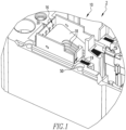
- FIGS. 1-3 depict different views of an electrical switching apparatus (e.g ., without limitation, multi-pole circuit breaker 2), in accordance with one non-limiting embodiment of the disclosed concept.
- the example circuit breaker 2 has a plurality of poles 4,6,8, as shown in FIG. 2 .
- poles 6,8 are configured substantially the same as pole 4.
- Pole 4 has an arc interruption system 10, a movable contact (see, for example, movable contact 12, shown in FIGS. 2 and 5 ), and a line conductor 13 ( FIGS. 3-5 ) having a stationary contact 14 ( FIGS. 3-5 ).
- the movable contact 12 is structured to move into and out of engagement with the stationary contact 14 in a generally well known manner in order to close and open an electrical circuit, respectively. Furthermore, the separable contacts 12,14 are structured to generate debris when tripping open in response to an electrical fault.
- the arc interruption system 10 includes an arc chute 16 and a slot motor (e.g., a number of generally U-shaped ferromagnetic laminations 19).
- the arc chute 16 is located at or about the separable contacts 12,14 and functions to cool and split an arc that is generated by the separable contacts 12,14 tripping open in response to an electrical fault.
- the laminations 19 advantageously assist with accelerating the movable contact 12 during opening, thereby improving the interruption performance by reducing arcing energies.
- the arc chute 16 has a plurality of splitter plates 18 each having an edge portion 20 and at least one distal portion 22,24 ( FIG. 2 ) located opposite and distal the edge portion 20.
- the edge portion 20 is located at a rear portion of the arc chute 16, for example, opposite and distal the separable contacts 12,14 such that the movable contact 12 moves in a plane perpendicular to the edge portion 20.
- a suitable alternative arc chute (not shown) to employ splitter plates having only one distal portion opposite an edge portion.
- the circuit breaker 2 includes a novel debris barrier 50 that redirects debris generated from tripping open of the separable contacts 12,14. This protects critical functional areas of the circuit breaker 2, thereby minimizing the likelihood that the circuit breaker 2 will malfunction from debris accumulation.
- FIGS. 6-8 show different views of the debris barrier 50.
- the debris barrier 50 is a unitary component made from a single piece of thermoset material.
- the debris barrier 50 can better withstand arcing (e.g., is less likely to melt under tough arcing loads), as compared to a similarly structured thermoplastic debris barrier.
- certain regulations e.g ., without limitation, regulations in the nuclear industry
- manufacture of the debris barrier 50 is advantageously relatively simple in that no separate assembly steps are required.
- the debris barrier 50 is generally U-shaped and includes a first leg 52, a second leg 54, and a middle portion 56 connecting the first leg 52 to the second leg 54.
- the middle portion 56 is preferably coupled to and reliably maintained on the stationary contact 14.
- the movable contact 12 is structured to move in a plane located between the first and second legs 52,54 (see, for example, FIG. 2 , wherein the movable contact 12 is located between the legs 52,54).
- the legs 52,54 include respective first barrier portions 58,60, respective second barrier portions 62,64 extending from the respective first barrier portions 58,60, and respective pocket portions 70,72 extending from the respective first barrier portions 58,60 away from the respective second barrier portions 62,64.
- the pocket portions 70,72 are a number of walls that are cooperatively structured to receive the laminations 19 ( FIGS. 1 , 2 , 4, and 5 ).
- the debris barrier 50 advantageously functions to redirect debris, as will be discussed below, and further to house and maintain the laminations 19.
- the first barrier portions 58,60 include respective barrier surfaces 59,61 that face away from the respective pocket portions 70,72.
- the second barrier portions 62,64 have respective barrier surfaces 63,65 that each extend at obtuse angles from one of the barrier surfaces 59,61 away from the respective pocket portions 70,72. Furthermore, the second barrier portions 62,64 have extension portions 66,68 extending from the respective barrier surfaces 63,65 and being located generally perpendicular to the respective first barrier portions 58,60.
- the first barrier portions 58,60 are located at or about the distal portions 22,24 of the splitter plates 18.
- the distal portions 22,24 engage the first barrier portions 58,60.
- the second barrier portions 62,64 extend from the first barrier portions 58,60 toward the edge portion 20. Accordingly, the second barrier portions 62,64 are located between the first distal portion 22 and the second distal portion 24.
- the second barrier portions 62,64 which are the portions of the debris barrier 50 extending away from the laminations 19, overlap a portion of the splitter plates 18 and/or extend into an interior of the arc chute 16.
- the second barrier portions 62,64 protrude outwardly from the first barrier portions 58,60 away from the laminations 19 and past the distal portions 22,24.
- the second barrier portions 62,64 are located substantially closer to the edge portion 20 than the distal portions 22,24.
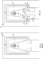
- FIGS. 9 and 10 show simplified plan views of a conventional arc chute 116, and the arc chute 16 of the disclosed concept which is employed with the debris barrier 50, respectively.
- debris which is represented by dashed lines/arrows, is free to move from a source (e.g., an arcing region proximate a pair of separable contacts 112,114) away from an edge portion 120 of a splitter plate 118. It will be appreciated that movement of debris along the paths shown by the dashed lines/arrows in FIG.
- the debris barrier 50 results in a redirection of debris away from the critical functional areas and back toward the edge portion 20. More specifically, after the debris is generated by the arc erosion of surrounding materials while the separable contacts 12,14 trip open, the debris is moved toward the edge portion 20 and then away from the edge portion 20 by walls of the arc chute 16. However, rather than continuing to travel away from the edge portion 20, the first barrier portions 58,60 and the second barrier portions 62,64 cooperatively function to redirect the debris back toward the edge portion 20. Furthermore, the obtuse angles with which the barrier surfaces 63,65 extend from the first barrier portions 58,60 further aide with redirecting debris. Accordingly, the likelihood that debris will accumulate on critical functional areas of the circuit breaker 2 is significantly minimized, advantageously prolonging the life of the circuit breaker 2 and minimizing the possibility of a resulting malfunction.
- FIG. 11 shows an example electrical switching apparatus (e.g., without limitation, multi-pole circuit breaker 202), not according to the invention.
- the example circuit breaker 202 includes a debris barrier 250, which is also shown in FIG. 12 .
- the second barrier portions 262,264 of the legs 252,254 of the debris barrier 250 each include a corresponding plurality of grooved regions 263,265.
- the grooved regions 263,265 are structured to receive the distal portions 222,224 of the splitter plates 218 (see, for example, FIG. 11 ). That is, the debris barrier 250, in addition to redirecting debris, further functions to maintain the splitter plates 218 thereon and also prevents the arc from staying there and causing erosion of the arc plate legs.
- the debris barrier 250 is also structured to receive the U-shaped ferromagnetic laminations 219.
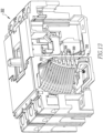
- FIG. 13 shows an example electrical switching apparatus (e.g ., without limitation, multi-pole circuit breaker 302), not according to the invention.
- the example circuit breaker 302 includes a debris barrier 350, which is also shown in FIGS. 14 and 15 .
- the legs 352,354 of the debris barrier 350 each have a first end 361,365 and a second end 363,367 located opposite and distal the corresponding first end 361,365.
- the second ends 363,367 are located at the middle portion 356.
- the first barrier portions 358,360 of the legs 352,354 each have a corresponding plurality of grooved regions 369,371 located at a peripheral portion of the legs 352,354.
- the grooved regions 369,371 extend longitudinally from the corresponding first ends 361,365 to the corresponding second ends 363,367. It will be appreciated that the grooved regions 369,371 advantageously function to provide a reservoir for debris (i.e. , debris generated by separable contacts tripping open) to collect. That is, rather than being entirely redirected toward the second barrier portions 362,364, a significant portion of the debris is structured to be caught in the grooved regions 369,371, thereby further protecting critical functional areas of the circuit breaker 302. Moreover, it will be appreciated with reference to FIG. 13 that the distal portions of the splitter plates are spaced from the first barrier portions 358,360.
- the debris barrier 350 is slightly V-shaped. That is, the legs 352,354 are spaced a greater distance from each other proximate a top of the debris barrier 350 than at an opposing bottom of the debris barrier 350. As a result, when the debris barrier 350 is inserted into the circuit breaker 302, the debris barrier 350 will be relatively tightly maintained therein. Additionally, it will be appreciated that the circuit breaker 302 is devoid of U-shaped ferromagnetic laminations. That is, the debris barrier 350 in the example of FIGS. 13-15 is not structured to house and maintain U-shaped ferromagnetic laminations.
Landscapes
- Arc-Extinguishing Devices That Are Switches (AREA)
Claims (6)
- Rückstandsbarriere (50) für eine elektrische Schaltvorrichtung (2), wobei die genannte elektrische Schaltvorrichtung (2) ein Paar trennbarer Kontakte (12, 14) und ein Lichtbogenunterbrechungssystem (10) umfasst, das eine Lichtbogenrutsche (16) umfasst, die am oder um das genannte Paar trennbarer Kontakte (12, 14) angeordnet ist, wobei die genannte Lichtbogenrutsche (16) eine Mehrzahl von Teilerplatten (18) umfasst, die jeweils einen Kantenabschnitt (20) und mindestens einen distalen Abschnitt (22, 24) aufweist, der gegenüberliegend und distal zum genannten Kantenabschnitt (20) angeordnet ist, wobei die genannte Rückstandsbarriere (50) umfasst:einen ersten Schenkel (52);einen zweiten Schenkel (54); undeinen Mittelabschnitt (56), der den genannten ersten Schenkel (52) und den genannten zweiten Schenkel (54) verbindet, wobei der Mittelabschnitt (56) so strukturiert ist, dass er mit einem des genannten Paares trennbarer Kontakte (12, 14) gekoppelt werden kann,wobei der genannte erste Schenkel (52) und der genannte zweite Schenkel (54) jeweils einen ersten Barriereabschnitt (58, 60) und einen zweiten Barriereabschnitt (62, 64) umfassen, der sich vom genannten ersten Barriereabschnitt (58, 60) erstreckt, wobei der genannte erste Barriereabschnitt (58, 60) so strukturiert ist, dass er am oder um den genannten, mindestens einen distalen Abschnitt (22, 24) angeordnet ist, der genannte zweite Barriereabschnitt (62, 64) so strukturiert ist, dass er sich vom genannten ersten Barriereabschnitt (58, 60) in Richtung des genannten Kantenabschnitts (20) erstreckt,wobei der genannte erste Schenkel ferner einen ersten Taschenabschnitt (70) umfasst, der sich vom genannten ersten Barriereabschnitt des genannten ersten Schenkels weg vom genannten zweiten Barriereabschnitt des genannten ersten Schenkels erstreckt, wobei der genannte zweite Schenkel ferner einen zweiten Taschenabschnitt (72) umfasst, der sich vom genannten ersten Barriereabschnitt des genannten zweiten Schenkels weg vom genannten zweiten Barriereabschnitt des genannten zweiten Schenkels erstreckt, wobei das Lichtbogenunterbrechungssystem ferner eine Anzahl U-förmiger Laminierungen (19) umfasst, und wobei der genannte erste Taschenabschnitt und der genannte zweite Taschenabschnitt so strukturiert sind, dass sie die genannte Anzahl U-förmiger Laminierungen aufnehmen,wobei der genannte erste Barriereabschnitt (58) des genannten ersten Schenkels (52) eine erste Barrierefläche (59) aufweist, die genannte erste Barrierefläche vom genannten ersten Taschenabschnitt (70) weg weist; wobei der genannte zweite Barriereabschnitt (62) des genannten ersten Schenkels eine zweite Barrierefläche (63) aufweist, die genannte zweite Barrierefläche in einem stumpfen Winkel von der genannten ersten Barrierefläche (59) weg vom genannten ersten Taschenabschnitt (70) verläuft; wobei der genannte erste Barriereabschnitt (60) des genannten zweiten Schenkels (54) eine dritte Barrierefläche (61) aufweist, die genannte dritte Barrierefläche vom genannten zweiten Taschenabschnitt (72) weg weist; und wobei der genannte zweite Barriereabschnitt (64) des genannten zweiten Schenkels eine vierte Barrierefläche (65) aufweist, die genannte vierte Barrierefläche in einem stumpfen Winkel von der genannten dritten Barrierefläche (61) weg vom genannten zweiten Taschenabschnitt (72) verläuft.
- Rückstandsbarriere nach Anspruch 1, wobei der genannte, mindestens eine distale Abschnitt einen ersten distalen Abschnitt (22) und einen zweiten distalen Abschnitt (24) umfasst, der gegenüberliegend und distal zum genannten ersten distalen Abschnitt angeordnet ist; und wobei der genannte zweite Barriereabschnitt (62) des genannten ersten Schenkels und der genannte zweite Barriereabschnitt (64) des genannten zweiten Schenkels jeweils so strukturiert sind, dass sie zwischen dem genannten ersten distalen Abschnitt und dem genannten zweiten distalen Abschnitt angeordnet sind.
- Rückstandsbarriere nach Anspruch 2, wobei der genannte zweite Barriereabschnitt des genannten ersten Schenkels einen Verlängerungsabschnitt (66) umfasst, der im Wesentlichen senkrecht zum genannten ersten Barriereabschnitt des genannten ersten Schenkels angeordnet ist; und wobei der genannte zweite Barriereabschnitt des genannten zweiten Schenkels einen Verlängerungsabschnitt (68) umfasst, der im Wesentlichen senkrecht zum genannten ersten Barriereabschnitt des genannten zweiten Schenkels angeordnet ist.
- Rückstandsbarriere nach Anspruch 1, wobei die genannte Rückstandsbarriere eine einheitliche Komponente ist, die aus einem einzigen Stück aus duroplastischem Material hergestellt ist.
- Elektrische Schaltvorrichtung (2), umfassend:
ein Paar trennbarer Kontakte (12, 14);ein Lichtbogenunterbrechungssystem (10), das eine Lichtbogenrutsche (16) umfasst, die am oder um das genannte Paar trennbarer Kontakte (12, 14) angeordnet ist, wobei die genannte Lichtbogenrutsche (16) eine Mehrzahl von Teilerplatten (18) umfasst, die jeweils einen Kantenabschnitt (20) und mindestens einen distalen Abschnitt (22, 24) aufweisen, der gegenüber und distal zum genannten Kantenabschnitt (20) angeordnet ist; undeine Rückstandsbarriere (50), umfassend:einen ersten Schenkel (52),einen zweiten Schenkel (54) undeinen Mittelabschnitt (56), der den genannten ersten Schenkel (52) und den genannten zweiten Schenkel (54) verbindet, wobei der Mittelabschnitt (56) so strukturiert ist, dass er mit einem des genannten Paares trennbarer Kontakte (12, 14) gekoppelt werden kann,wobei der genannte erste Schenkel (52) und der genannte zweite Schenkel (54) jeweils einen ersten Barriereabschnitt (58, 60) und einen zweiten Barriereabschnitt (62, 64) umfassen, der sich vom genannten ersten Barriereabschnitt (58, 60) erstreckt, wobei der genannte erste Barriereabschnitt (58, 60) so angeordnet ist, dass er am oder um den genannten, mindestens einen distalen Abschnitt (22, 24) angeordnet ist, der genannte zweite Barriereabschnitt (62, 64) sich vom genannten ersten Barriereabschnitt (58, 60) in Richtung des genannten Kantenabschnitts (20) erstreckt,wobei der genannte erste Schenkel ferner einen ersten Taschenabschnitt (70) umfasst, der sich vom genannten ersten Barriereabschnitt des genannten ersten Schenkels weg vom genannten zweiten Barriereabschnitt des genannten ersten Schenkels erstreckt, wobei der genannte zweite Schenkel ferner einen zweiten Taschenabschnitt (72) umfasst, der sich vom genannten ersten Barriereabschnitt des genannten zweiten Schenkels weg vom genannten zweiten Barriereabschnitt des genannten zweiten Schenkels erstreckt, wobei das Lichtbogenunterbrechungssystem ferner eine Anzahl U-förmiger Laminierungen (19) umfasst, und wobei der genannte erste Taschenabschnitt und der genannte zweite Taschenabschnitt so strukturiert sind, dass sie die genannte Anzahl U-förmiger Laminierungen aufnehmen,wobei der genannte erste Barriereabschnitt (58) des genannten ersten Schenkels (52) eine erste Barrierefläche (59) aufweist, die genannte erste Barrierefläche vom genannten ersten Taschenabschnitt (70) weg weist; wobei der genannte zweite Barriereabschnitt (62) des genannten ersten Schenkels eine zweite Barrierefläche (63) aufweist, die genannte zweite Barrierefläche in einem stumpfen Winkel von der genannten ersten Barrierefläche (59) weg vom genannten ersten Taschenabschnitt (70) verläuft; wobei der genannte erste Barriereabschnitt (60) des genannten zweiten Schenkels (54) eine dritte Barrierefläche (61) aufweist, die genannte dritte Barrierefläche vom genannten zweiten Taschenabschnitt (72) weg weist; und wobei der genannte zweite Barriereabschnitt (64) des genannten zweiten Schenkels eine vierte Barrierefläche (65) aufweist, die genannte vierte Barrierefläche in einem stumpfen Winkel von der genannten dritten Barrierefläche (61) weg vom genannten zweiten Taschenabschnitt (72) verläuft. - Elektrische Schaltvorrichtung nach Anspruch 5, wobei der genannte, mindestenseine distale Abschnitt einen ersten distalen Abschnitt (22) umfasst, und einen zweiten distalen Abschnitt (24), der gegenüberliegend und distal zum genannten ersten distalen Abschnitt angeordnet ist;und wobei der genannte zweite Barriereabschnitt (62) des genannten ersten Schenkels und der genannte zweite Barriereabschnitt (64) des genannten zweiten Schenkels jeweils zwischen dem genannten ersten distalen Abschnitt und dem genannten zweiten distalen Abschnitt angeordnet sind.
Priority Applications (1)
| Application Number | Priority Date | Filing Date | Title |
|---|---|---|---|
| EP24195820.6A EP4459657A3 (de) | 2017-07-18 | 2018-06-25 | Elektrische schaltvorrichtung und fremdkörpersperre dafür |
Applications Claiming Priority (2)
| Application Number | Priority Date | Filing Date | Title |
|---|---|---|---|
| US15/652,619 US10128069B1 (en) | 2017-07-18 | 2017-07-18 | Electrical switching apparatus and debris barrier therefor |
| PCT/IB2018/054666 WO2019016630A1 (en) | 2017-07-18 | 2018-06-25 | ELECTRICAL SWITCHING APPARATUS AND DEBRIS BARRIER THEREOF |
Related Child Applications (2)
| Application Number | Title | Priority Date | Filing Date |
|---|---|---|---|
| EP24195820.6A Division-Into EP4459657A3 (de) | 2017-07-18 | 2018-06-25 | Elektrische schaltvorrichtung und fremdkörpersperre dafür |
| EP24195820.6A Division EP4459657A3 (de) | 2017-07-18 | 2018-06-25 | Elektrische schaltvorrichtung und fremdkörpersperre dafür |
Publications (2)
| Publication Number | Publication Date |
|---|---|
| EP3655979A1 EP3655979A1 (de) | 2020-05-27 |
| EP3655979B1 true EP3655979B1 (de) | 2024-10-16 |
Family
ID=63077918
Family Applications (2)
| Application Number | Title | Priority Date | Filing Date |
|---|---|---|---|
| EP24195820.6A Pending EP4459657A3 (de) | 2017-07-18 | 2018-06-25 | Elektrische schaltvorrichtung und fremdkörpersperre dafür |
| EP18749119.6A Active EP3655979B1 (de) | 2017-07-18 | 2018-06-25 | Elektrische schaltvorrichtung und ablagerungsbarriere dafür |
Family Applications Before (1)
| Application Number | Title | Priority Date | Filing Date |
|---|---|---|---|
| EP24195820.6A Pending EP4459657A3 (de) | 2017-07-18 | 2018-06-25 | Elektrische schaltvorrichtung und fremdkörpersperre dafür |
Country Status (4)
| Country | Link |
|---|---|
| US (1) | US10128069B1 (de) |
| EP (2) | EP4459657A3 (de) |
| CN (1) | CN110998771B (de) |
| WO (1) | WO2019016630A1 (de) |
Families Citing this family (6)
| Publication number | Priority date | Publication date | Assignee | Title |
|---|---|---|---|---|
| CN111755299B (zh) * | 2019-03-29 | 2022-07-05 | Ls产电株式会社 | 配线用断路器的灭弧装置 |
| KR102349754B1 (ko) * | 2019-12-06 | 2022-01-11 | 엘에스일렉트릭(주) | 아크 박스 및 이를 포함하는 전자 접촉기 |
| KR102542379B1 (ko) * | 2020-03-03 | 2023-06-12 | 엘에스일렉트릭(주) | 아크 소호 조립체 |
| CN213781970U (zh) * | 2020-11-12 | 2021-07-23 | 伊顿电气有限公司 | 断路器 |
| US11749475B2 (en) * | 2021-11-12 | 2023-09-05 | Eaton Intelligent Power Limited | Arc chute debris blocker |
| EP4632779A1 (de) * | 2024-04-08 | 2025-10-15 | Wöhner Besitz GmbH | Elektrischer schalter |
Citations (1)
| Publication number | Priority date | Publication date | Assignee | Title |
|---|---|---|---|---|
| CN106449327A (zh) * | 2016-09-23 | 2017-02-22 | 德力西电气有限公司 | 一种用于灭弧室的灭弧罩 |
Family Cites Families (27)
| Publication number | Priority date | Publication date | Assignee | Title |
|---|---|---|---|---|
| US2244061A (en) * | 1940-07-31 | 1941-06-03 | Ite Circuit Breaker Ltd | Arc quencher |
| US5589672A (en) * | 1994-06-14 | 1996-12-31 | Fuji Electric Co., Ltd. | Circuit breaker with arc quenching device and vent |
| JP3216776B2 (ja) * | 1994-06-14 | 2001-10-09 | 富士電機株式会社 | 回路遮断器 |
| US6248970B1 (en) * | 1999-11-05 | 2001-06-19 | Siemens Energy & Automation, Inc. | ARC chute for a molded case circuit breaker |
| DE19956656A1 (de) * | 1999-11-25 | 2001-05-31 | Moeller Gmbh | Strombegrenzende Kontaktanordnung |
| IT1314358B1 (it) * | 1999-12-31 | 2002-12-09 | Abb Ricerca Spa | Camera d'arco per interruttori di bassa tensione |
| US6281459B1 (en) | 2000-04-21 | 2001-08-28 | Eaton Corporation | Circuit interrupter having an improved slot motor assembly |
| US6831536B1 (en) | 2003-08-29 | 2004-12-14 | Eaton Corporation | Circuit breaker slot motor having a stepped out portion |
| US6970059B2 (en) | 2003-12-11 | 2005-11-29 | Eaton Corporation | Slot motor including legs engaging openings of circuit breaker housing and electrical switching apparatus employing the same |
| KR20060035194A (ko) * | 2004-10-21 | 2006-04-26 | 엘에스산전 주식회사 | 배선용 차단기의 소호장치 |
| CN2743961Y (zh) * | 2004-11-11 | 2005-11-30 | 常熟开关制造有限公司(原常熟开关厂) | 断路器的灭弧装置 |
| US7348514B2 (en) | 2006-04-12 | 2008-03-25 | Eaton Corporation | Slot motor and circuit breaker including the same |
| US7358840B1 (en) | 2006-09-28 | 2008-04-15 | Eaton Corporation | Electrical switching apparatus including a split core slot motor and method of installing a slot motor assembly in a circuit interrupter |
| US7532097B2 (en) | 2007-02-12 | 2009-05-12 | Eaton Corporation | Slot motor housing and circuit interrupter including the same |
| JP4655094B2 (ja) * | 2008-02-08 | 2011-03-23 | 富士電機機器制御株式会社 | 消弧用樹脂加工品、及びそれを用いた回路遮断器 |
| AT509277A1 (de) * | 2008-03-05 | 2011-07-15 | Moeller Gebaeudeautomation Gmbh | Schaltgerät |
| CN101546681B (zh) * | 2009-04-27 | 2010-12-29 | 常熟开关制造有限公司(原常熟开关厂) | 低压断路器 |
| CN101789322B (zh) * | 2010-01-27 | 2011-09-28 | 江苏辉能电气有限公司 | 一种带放射状灭弧栅片的组合式灭弧室 |
| US8222983B2 (en) | 2010-12-08 | 2012-07-17 | Eaton Corporation | Single direct current arc chamber, and bi-directional direct current electrical switching apparatus employing the same |
| JP5682450B2 (ja) * | 2011-05-23 | 2015-03-11 | 富士電機機器制御株式会社 | 回路遮断器 |
| CN103383901B (zh) * | 2012-05-04 | 2015-08-12 | 伊顿电气有限公司 | 一种一体式隔弧装置 |
| US8368492B1 (en) | 2012-08-24 | 2013-02-05 | Eaton Corporation | Bidirectional direct current electrical switching apparatus |
| US8847096B2 (en) * | 2012-09-05 | 2014-09-30 | Eaton Corporation | Single direct current arc chute, and bi-directional direct current electrical switching apparatus employing the same |
| US9006601B2 (en) | 2013-03-13 | 2015-04-14 | Eaton Corporation | Arc chamber for bi-directional DC |
| US9396890B2 (en) * | 2014-05-28 | 2016-07-19 | Eaton Corporation | Electrical switching apparatus, and arc chute assembly and barrier member therefor |
| JP6237481B2 (ja) * | 2014-06-10 | 2017-11-29 | 三菱電機株式会社 | 回路遮断器 |
| US9653237B1 (en) | 2015-12-03 | 2017-05-16 | Eaton Corporation | Electrical switching apparatus and slot motor therefor |
-
2017
- 2017-07-18 US US15/652,619 patent/US10128069B1/en active Active
-
2018
- 2018-06-25 CN CN201880054350.2A patent/CN110998771B/zh active Active
- 2018-06-25 WO PCT/IB2018/054666 patent/WO2019016630A1/en not_active Ceased
- 2018-06-25 EP EP24195820.6A patent/EP4459657A3/de active Pending
- 2018-06-25 EP EP18749119.6A patent/EP3655979B1/de active Active
Patent Citations (1)
| Publication number | Priority date | Publication date | Assignee | Title |
|---|---|---|---|---|
| CN106449327A (zh) * | 2016-09-23 | 2017-02-22 | 德力西电气有限公司 | 一种用于灭弧室的灭弧罩 |
Also Published As
| Publication number | Publication date |
|---|---|
| EP3655979A1 (de) | 2020-05-27 |
| US10128069B1 (en) | 2018-11-13 |
| WO2019016630A1 (en) | 2019-01-24 |
| CN110998771A (zh) | 2020-04-10 |
| CN110998771B (zh) | 2023-09-12 |
| EP4459657A3 (de) | 2024-12-11 |
| EP4459657A2 (de) | 2024-11-06 |
Similar Documents
| Publication | Publication Date | Title |
|---|---|---|
| EP3223293B1 (de) | Elektrische schaltvorrichtung und lichtbogenkammeranordnung sowie zugehöriges schaltungsschutzverfahren | |
| US10128069B1 (en) | Electrical switching apparatus and debris barrier therefor | |
| EP3149755B1 (de) | Elektrische schaltung, lichtbogenkammeranordnung und sperrelement dafür | |
| US6518530B2 (en) | Current-limiting contact arrangement | |
| US7716816B2 (en) | Method of manufacturing a switch assembly | |
| CA2271247C (en) | Electrical switching apparatus having arc runner integral with stationary arcing contact | |
| EP1906430B1 (de) | Elektrische Schaltvorrichtung mit einem Schlitzmotor mit geteiltem Kern und Verfahren zur Installation einer Schlitzmotoranordnung in einem Schutzschalter | |
| US20130206729A1 (en) | Switch unit with arc-extinguishing units | |
| KR20140012034A (ko) | 회로 차단기 | |
| EP1858041A2 (de) | Elektrische Schaltvorrichtung sowie bewegliche Kontaktanordnung und Abschirmung dafür | |
| EP3384512B1 (de) | Elektrische schaltvorrichtung und schlitzmotor dafür | |
| EP2005459B1 (de) | Schlitzmotor und damit versehener schutzschalter | |
| MXPA97007781A (en) | Electrical current switch apparatus with arc tornad extinguishing mechanism | |
| EP2048678B1 (de) | Gas abgebende Isolatoranordnung, Leiteranordnung und elektrische Schaltvorrichtung die dasselbe einsetzt | |
| KR20140079302A (ko) | 개폐기 | |
| EP1414057B1 (de) | Luftunterbrecherschalter | |
| JPS61256542A (ja) | 短絡回路電流に対する保護スイツチング装置 | |
| JPH0116257Y2 (de) | ||
| US5291167A (en) | Arc extinguishing device having a focused field | |
| US10068735B2 (en) | Electrical switching apparatus, and operating mechanism and lever assembly therefor | |
| EP3699941B1 (de) | Schaltanlage | |
| KR20180002910U (ko) | 가정용 회로차단기 | |
| KR200496737Y1 (ko) | 배선용 차단기의 트립 장치 | |
| JP2025114949A (ja) | 回路遮断器 |
Legal Events
| Date | Code | Title | Description |
|---|---|---|---|
| STAA | Information on the status of an ep patent application or granted ep patent |
Free format text: STATUS: UNKNOWN |
|
| STAA | Information on the status of an ep patent application or granted ep patent |
Free format text: STATUS: THE INTERNATIONAL PUBLICATION HAS BEEN MADE |
|
| PUAI | Public reference made under article 153(3) epc to a published international application that has entered the european phase |
Free format text: ORIGINAL CODE: 0009012 |
|
| STAA | Information on the status of an ep patent application or granted ep patent |
Free format text: STATUS: REQUEST FOR EXAMINATION WAS MADE |
|
| 17P | Request for examination filed |
Effective date: 20200207 |
|
| AK | Designated contracting states |
Kind code of ref document: A1 Designated state(s): AL AT BE BG CH CY CZ DE DK EE ES FI FR GB GR HR HU IE IS IT LI LT LU LV MC MK MT NL NO PL PT RO RS SE SI SK SM TR |
|
| AX | Request for extension of the european patent |
Extension state: BA ME |
|
| RIN1 | Information on inventor provided before grant (corrected) |
Inventor name: SCHALTENBRAND, BRIAN J. Inventor name: MCCARTHY, KELLY J. Inventor name: MALINGOWSKI, RICHARD P. Inventor name: RUEMPLER, CHRISTIAN Inventor name: GOTTSCHALK, ANDREW L. Inventor name: ZHOU, XIN |
|
| DAV | Request for validation of the european patent (deleted) | ||
| DAX | Request for extension of the european patent (deleted) | ||
| STAA | Information on the status of an ep patent application or granted ep patent |
Free format text: STATUS: EXAMINATION IS IN PROGRESS |
|
| 17Q | First examination report despatched |
Effective date: 20220420 |
|
| P01 | Opt-out of the competence of the unified patent court (upc) registered |
Effective date: 20230521 |
|
| GRAP | Despatch of communication of intention to grant a patent |
Free format text: ORIGINAL CODE: EPIDOSNIGR1 |
|
| STAA | Information on the status of an ep patent application or granted ep patent |
Free format text: STATUS: GRANT OF PATENT IS INTENDED |
|
| INTG | Intention to grant announced |
Effective date: 20240515 |
|
| GRAS | Grant fee paid |
Free format text: ORIGINAL CODE: EPIDOSNIGR3 |
|
| GRAA | (expected) grant |
Free format text: ORIGINAL CODE: 0009210 |
|
| STAA | Information on the status of an ep patent application or granted ep patent |
Free format text: STATUS: THE PATENT HAS BEEN GRANTED |
|
| AK | Designated contracting states |
Kind code of ref document: B1 Designated state(s): AL AT BE BG CH CY CZ DE DK EE ES FI FR GB GR HR HU IE IS IT LI LT LU LV MC MK MT NL NO PL PT RO RS SE SI SK SM TR |
|
| REG | Reference to a national code |
Ref country code: GB Ref legal event code: FG4D |
|
| REG | Reference to a national code |
Ref country code: CH Ref legal event code: EP Ref country code: DE Ref legal event code: R096 Ref document number: 602018075497 Country of ref document: DE |
|
| REG | Reference to a national code |
Ref country code: IE Ref legal event code: FG4D |
|
| REG | Reference to a national code |
Ref country code: LT Ref legal event code: MG9D |
|
| REG | Reference to a national code |
Ref country code: NL Ref legal event code: MP Effective date: 20241016 |
|
| REG | Reference to a national code |
Ref country code: AT Ref legal event code: MK05 Ref document number: 1733650 Country of ref document: AT Kind code of ref document: T Effective date: 20241016 |
|
| PG25 | Lapsed in a contracting state [announced via postgrant information from national office to epo] |
Ref country code: NL Free format text: LAPSE BECAUSE OF FAILURE TO SUBMIT A TRANSLATION OF THE DESCRIPTION OR TO PAY THE FEE WITHIN THE PRESCRIBED TIME-LIMIT Effective date: 20241016 |
|
| PG25 | Lapsed in a contracting state [announced via postgrant information from national office to epo] |
Ref country code: NL Free format text: LAPSE BECAUSE OF FAILURE TO SUBMIT A TRANSLATION OF THE DESCRIPTION OR TO PAY THE FEE WITHIN THE PRESCRIBED TIME-LIMIT Effective date: 20241016 |
|
| PG25 | Lapsed in a contracting state [announced via postgrant information from national office to epo] |
Ref country code: PT Free format text: LAPSE BECAUSE OF FAILURE TO SUBMIT A TRANSLATION OF THE DESCRIPTION OR TO PAY THE FEE WITHIN THE PRESCRIBED TIME-LIMIT Effective date: 20250217 Ref country code: HR Free format text: LAPSE BECAUSE OF FAILURE TO SUBMIT A TRANSLATION OF THE DESCRIPTION OR TO PAY THE FEE WITHIN THE PRESCRIBED TIME-LIMIT Effective date: 20241016 Ref country code: IS Free format text: LAPSE BECAUSE OF FAILURE TO SUBMIT A TRANSLATION OF THE DESCRIPTION OR TO PAY THE FEE WITHIN THE PRESCRIBED TIME-LIMIT Effective date: 20250216 |
|
| PG25 | Lapsed in a contracting state [announced via postgrant information from national office to epo] |
Ref country code: FI Free format text: LAPSE BECAUSE OF FAILURE TO SUBMIT A TRANSLATION OF THE DESCRIPTION OR TO PAY THE FEE WITHIN THE PRESCRIBED TIME-LIMIT Effective date: 20241016 |
|
| PG25 | Lapsed in a contracting state [announced via postgrant information from national office to epo] |
Ref country code: BG Free format text: LAPSE BECAUSE OF FAILURE TO SUBMIT A TRANSLATION OF THE DESCRIPTION OR TO PAY THE FEE WITHIN THE PRESCRIBED TIME-LIMIT Effective date: 20241016 |
|
| PG25 | Lapsed in a contracting state [announced via postgrant information from national office to epo] |
Ref country code: ES Free format text: LAPSE BECAUSE OF FAILURE TO SUBMIT A TRANSLATION OF THE DESCRIPTION OR TO PAY THE FEE WITHIN THE PRESCRIBED TIME-LIMIT Effective date: 20241016 |
|
| PG25 | Lapsed in a contracting state [announced via postgrant information from national office to epo] |
Ref country code: NO Free format text: LAPSE BECAUSE OF FAILURE TO SUBMIT A TRANSLATION OF THE DESCRIPTION OR TO PAY THE FEE WITHIN THE PRESCRIBED TIME-LIMIT Effective date: 20250116 |
|
| PG25 | Lapsed in a contracting state [announced via postgrant information from national office to epo] |
Ref country code: AT Free format text: LAPSE BECAUSE OF FAILURE TO SUBMIT A TRANSLATION OF THE DESCRIPTION OR TO PAY THE FEE WITHIN THE PRESCRIBED TIME-LIMIT Effective date: 20241016 Ref country code: LV Free format text: LAPSE BECAUSE OF FAILURE TO SUBMIT A TRANSLATION OF THE DESCRIPTION OR TO PAY THE FEE WITHIN THE PRESCRIBED TIME-LIMIT Effective date: 20241016 Ref country code: GR Free format text: LAPSE BECAUSE OF FAILURE TO SUBMIT A TRANSLATION OF THE DESCRIPTION OR TO PAY THE FEE WITHIN THE PRESCRIBED TIME-LIMIT Effective date: 20250117 |
|
| PG25 | Lapsed in a contracting state [announced via postgrant information from national office to epo] |
Ref country code: PL Free format text: LAPSE BECAUSE OF FAILURE TO SUBMIT A TRANSLATION OF THE DESCRIPTION OR TO PAY THE FEE WITHIN THE PRESCRIBED TIME-LIMIT Effective date: 20241016 |
|
| PG25 | Lapsed in a contracting state [announced via postgrant information from national office to epo] |
Ref country code: RS Free format text: LAPSE BECAUSE OF FAILURE TO SUBMIT A TRANSLATION OF THE DESCRIPTION OR TO PAY THE FEE WITHIN THE PRESCRIBED TIME-LIMIT Effective date: 20250116 |
|
| PG25 | Lapsed in a contracting state [announced via postgrant information from national office to epo] |
Ref country code: SM Free format text: LAPSE BECAUSE OF FAILURE TO SUBMIT A TRANSLATION OF THE DESCRIPTION OR TO PAY THE FEE WITHIN THE PRESCRIBED TIME-LIMIT Effective date: 20241016 |
|
| PGFP | Annual fee paid to national office [announced via postgrant information from national office to epo] |
Ref country code: DE Payment date: 20250520 Year of fee payment: 8 |
|
| PG25 | Lapsed in a contracting state [announced via postgrant information from national office to epo] |
Ref country code: DK Free format text: LAPSE BECAUSE OF FAILURE TO SUBMIT A TRANSLATION OF THE DESCRIPTION OR TO PAY THE FEE WITHIN THE PRESCRIBED TIME-LIMIT Effective date: 20241016 |
|
| PGFP | Annual fee paid to national office [announced via postgrant information from national office to epo] |
Ref country code: IT Payment date: 20250520 Year of fee payment: 8 |
|
| REG | Reference to a national code |
Ref country code: DE Ref legal event code: R097 Ref document number: 602018075497 Country of ref document: DE |
|
| PG25 | Lapsed in a contracting state [announced via postgrant information from national office to epo] |
Ref country code: EE Free format text: LAPSE BECAUSE OF FAILURE TO SUBMIT A TRANSLATION OF THE DESCRIPTION OR TO PAY THE FEE WITHIN THE PRESCRIBED TIME-LIMIT Effective date: 20241016 |
|
| PGFP | Annual fee paid to national office [announced via postgrant information from national office to epo] |
Ref country code: FR Payment date: 20250520 Year of fee payment: 8 |
|
| PG25 | Lapsed in a contracting state [announced via postgrant information from national office to epo] |
Ref country code: RO Free format text: LAPSE BECAUSE OF FAILURE TO SUBMIT A TRANSLATION OF THE DESCRIPTION OR TO PAY THE FEE WITHIN THE PRESCRIBED TIME-LIMIT Effective date: 20241016 |
|
| PG25 | Lapsed in a contracting state [announced via postgrant information from national office to epo] |
Ref country code: SK Free format text: LAPSE BECAUSE OF FAILURE TO SUBMIT A TRANSLATION OF THE DESCRIPTION OR TO PAY THE FEE WITHIN THE PRESCRIBED TIME-LIMIT Effective date: 20241016 |
|
| PG25 | Lapsed in a contracting state [announced via postgrant information from national office to epo] |
Ref country code: CZ Free format text: LAPSE BECAUSE OF FAILURE TO SUBMIT A TRANSLATION OF THE DESCRIPTION OR TO PAY THE FEE WITHIN THE PRESCRIBED TIME-LIMIT Effective date: 20241016 |
|
| PLBE | No opposition filed within time limit |
Free format text: ORIGINAL CODE: 0009261 |
|
| STAA | Information on the status of an ep patent application or granted ep patent |
Free format text: STATUS: NO OPPOSITION FILED WITHIN TIME LIMIT |
|
| PG25 | Lapsed in a contracting state [announced via postgrant information from national office to epo] |
Ref country code: SE Free format text: LAPSE BECAUSE OF FAILURE TO SUBMIT A TRANSLATION OF THE DESCRIPTION OR TO PAY THE FEE WITHIN THE PRESCRIBED TIME-LIMIT Effective date: 20241016 |
|
| 26N | No opposition filed |
Effective date: 20250717 |
|
| REG | Reference to a national code |
Ref country code: CH Ref legal event code: H13 Free format text: ST27 STATUS EVENT CODE: U-0-0-H10-H13 (AS PROVIDED BY THE NATIONAL OFFICE) Effective date: 20260127 |
|
| PG25 | Lapsed in a contracting state [announced via postgrant information from national office to epo] |
Ref country code: MC Free format text: LAPSE BECAUSE OF FAILURE TO SUBMIT A TRANSLATION OF THE DESCRIPTION OR TO PAY THE FEE WITHIN THE PRESCRIBED TIME-LIMIT Effective date: 20241016 |
|
| PG25 | Lapsed in a contracting state [announced via postgrant information from national office to epo] |
Ref country code: LU Free format text: LAPSE BECAUSE OF NON-PAYMENT OF DUE FEES Effective date: 20250625 |
|
| GBPC | Gb: european patent ceased through non-payment of renewal fee |
Effective date: 20250625 |
|
| REG | Reference to a national code |
Ref country code: BE Ref legal event code: MM Effective date: 20250630 |
|
| PG25 | Lapsed in a contracting state [announced via postgrant information from national office to epo] |
Ref country code: GB Free format text: LAPSE BECAUSE OF NON-PAYMENT OF DUE FEES Effective date: 20250625 |
|
| PG25 | Lapsed in a contracting state [announced via postgrant information from national office to epo] |
Ref country code: IE Free format text: LAPSE BECAUSE OF NON-PAYMENT OF DUE FEES Effective date: 20250625 |
|
| PG25 | Lapsed in a contracting state [announced via postgrant information from national office to epo] |
Ref country code: BE Free format text: LAPSE BECAUSE OF NON-PAYMENT OF DUE FEES Effective date: 20250630 |
|
| PG25 | Lapsed in a contracting state [announced via postgrant information from national office to epo] |
Ref country code: CH Free format text: LAPSE BECAUSE OF NON-PAYMENT OF DUE FEES Effective date: 20250630 |