EP3656076B1 - Procédé et appareil de transmission et de réception d'un signal de référence dans un système de communication sans fil - Google Patents
Procédé et appareil de transmission et de réception d'un signal de référence dans un système de communication sans fil Download PDFInfo
- Publication number
- EP3656076B1 EP3656076B1 EP18879475.4A EP18879475A EP3656076B1 EP 3656076 B1 EP3656076 B1 EP 3656076B1 EP 18879475 A EP18879475 A EP 18879475A EP 3656076 B1 EP3656076 B1 EP 3656076B1
- Authority
- EP
- European Patent Office
- Prior art keywords
- srs
- transmission
- srs transmission
- slot
- base station
- Prior art date
- Legal status (The legal status is an assumption and is not a legal conclusion. Google has not performed a legal analysis and makes no representation as to the accuracy of the status listed.)
- Active
Links
Images



Classifications
-
- H—ELECTRICITY
- H04—ELECTRIC COMMUNICATION TECHNIQUE
- H04L—TRANSMISSION OF DIGITAL INFORMATION, e.g. TELEGRAPHIC COMMUNICATION
- H04L5/00—Arrangements affording multiple use of the transmission path
- H04L5/003—Arrangements for allocating sub-channels of the transmission path
- H04L5/0048—Allocation of pilot signals, i.e. of signals known to the receiver
-
- H—ELECTRICITY
- H04—ELECTRIC COMMUNICATION TECHNIQUE
- H04L—TRANSMISSION OF DIGITAL INFORMATION, e.g. TELEGRAPHIC COMMUNICATION
- H04L1/00—Arrangements for detecting or preventing errors in the information received
- H04L1/08—Arrangements for detecting or preventing errors in the information received by repeating transmission, e.g. Verdan system
-
- H—ELECTRICITY
- H04—ELECTRIC COMMUNICATION TECHNIQUE
- H04L—TRANSMISSION OF DIGITAL INFORMATION, e.g. TELEGRAPHIC COMMUNICATION
- H04L5/00—Arrangements affording multiple use of the transmission path
- H04L5/0001—Arrangements for dividing the transmission path
- H04L5/0003—Two-dimensional division
- H04L5/0005—Time-frequency
- H04L5/0007—Time-frequency the frequencies being orthogonal, e.g. OFDM(A) or DMT
-
- H—ELECTRICITY
- H04—ELECTRIC COMMUNICATION TECHNIQUE
- H04L—TRANSMISSION OF DIGITAL INFORMATION, e.g. TELEGRAPHIC COMMUNICATION
- H04L5/00—Arrangements affording multiple use of the transmission path
- H04L5/0001—Arrangements for dividing the transmission path
- H04L5/0003—Two-dimensional division
- H04L5/0005—Time-frequency
- H04L5/0007—Time-frequency the frequencies being orthogonal, e.g. OFDM(A) or DMT
- H04L5/0012—Hopping in multicarrier systems
-
- H—ELECTRICITY
- H04—ELECTRIC COMMUNICATION TECHNIQUE
- H04L—TRANSMISSION OF DIGITAL INFORMATION, e.g. TELEGRAPHIC COMMUNICATION
- H04L5/00—Arrangements affording multiple use of the transmission path
- H04L5/003—Arrangements for allocating sub-channels of the transmission path
- H04L5/0048—Allocation of pilot signals, i.e. of signals known to the receiver
- H04L5/0051—Allocation of pilot signals, i.e. of signals known to the receiver of dedicated pilots, i.e. pilots destined for a single user or terminal
-
- H—ELECTRICITY
- H04—ELECTRIC COMMUNICATION TECHNIQUE
- H04L—TRANSMISSION OF DIGITAL INFORMATION, e.g. TELEGRAPHIC COMMUNICATION
- H04L5/00—Arrangements affording multiple use of the transmission path
- H04L5/003—Arrangements for allocating sub-channels of the transmission path
- H04L5/0053—Allocation of signalling, i.e. of overhead other than pilot signals
-
- H—ELECTRICITY
- H04—ELECTRIC COMMUNICATION TECHNIQUE
- H04L—TRANSMISSION OF DIGITAL INFORMATION, e.g. TELEGRAPHIC COMMUNICATION
- H04L5/00—Arrangements affording multiple use of the transmission path
- H04L5/003—Arrangements for allocating sub-channels of the transmission path
- H04L5/0078—Timing of allocation
-
- H—ELECTRICITY
- H04—ELECTRIC COMMUNICATION TECHNIQUE
- H04L—TRANSMISSION OF DIGITAL INFORMATION, e.g. TELEGRAPHIC COMMUNICATION
- H04L5/00—Arrangements affording multiple use of the transmission path
- H04L5/0091—Signalling for the administration of the divided path, e.g. signalling of configuration information
- H04L5/0096—Indication of changes in allocation
- H04L5/0098—Signalling of the activation or deactivation of component carriers, subcarriers or frequency bands
-
- H—ELECTRICITY
- H04—ELECTRIC COMMUNICATION TECHNIQUE
- H04W—WIRELESS COMMUNICATION NETWORKS
- H04W72/00—Local resource management
- H04W72/04—Wireless resource allocation
- H04W72/044—Wireless resource allocation based on the type of the allocated resource
- H04W72/0446—Resources in time domain, e.g. slots or frames
-
- H—ELECTRICITY
- H04—ELECTRIC COMMUNICATION TECHNIQUE
- H04W—WIRELESS COMMUNICATION NETWORKS
- H04W72/00—Local resource management
- H04W72/20—Control channels or signalling for resource management
- H04W72/21—Control channels or signalling for resource management in the uplink direction of a wireless link, i.e. towards the network
-
- H—ELECTRICITY
- H04—ELECTRIC COMMUNICATION TECHNIQUE
- H04L—TRANSMISSION OF DIGITAL INFORMATION, e.g. TELEGRAPHIC COMMUNICATION
- H04L5/00—Arrangements affording multiple use of the transmission path
- H04L5/0001—Arrangements for dividing the transmission path
- H04L5/0014—Three-dimensional division
- H04L5/0023—Time-frequency-space
-
- H—ELECTRICITY
- H04—ELECTRIC COMMUNICATION TECHNIQUE
- H04L—TRANSMISSION OF DIGITAL INFORMATION, e.g. TELEGRAPHIC COMMUNICATION
- H04L5/00—Arrangements affording multiple use of the transmission path
- H04L5/0091—Signalling for the administration of the divided path, e.g. signalling of configuration information
- H04L5/0092—Indication of how the channel is divided
Definitions
- the present disclosure relates generally to wireless communication systems and methods and apparatuses for appropriately providing services in wireless communication systems.
- 5G communication systems are being developed to be implemented in a super-high frequency band (millimeter wave (mmWave)) (e.g., a band of about 60 GHz).
- mmWave millimeter wave
- ACM advanced coding modulation
- FQAM quadrature amplitude modulation
- SWSC sliding window superposition coding
- FBMC filter bank multi-carrier
- NOMA non-orthogonal multiple access
- SCMA sparse code multiple access
- the Internet has evolved to the Internet of things (IoT), where distributed elements such as objects exchange information with each other to process the information.
- Internet of everything (IoE) technology in which the IoT technology is combined with technology for processing big data through connection with a cloud server, is being newly provided.
- various technological elements such as a sensing technology, wired/wireless communication and network infrastructures, a service interface technology, and a security technology are required.
- technologies related to sensor networks for connecting objects, machine-to-machine (M2M) communication, and machine type communication (MTC) have been studied.
- intelligent Internet technology services may be provided to collect and analyze data obtained from connected objects and thus to create new values in human life.
- IT information technology
- the IoT may be applied to various fields such as smart homes, smart buildings, smart cities, smart cars or connected cars, smart grids, health care, smart home appliances, and advanced medical services.
- 5G communication systems to the IoT network.
- technologies related to sensor networks, M2M communication, MTC, etc. are implemented by using 5G communication technology including beamforming, MIMO, array antennas, etc.
- Application of a cloud RAN as the above-described big data processing technology may be an example of convergence of the 5G communication technology and the IoT technology.
- EP 2 482 590 A2 discloses a method in which user equipment transmits a nonperiodic sounding reference signal in a wireless communication system.
- the method comprises: a step of receiving a downlink control channel from a base station; a step of checking carrier indication field (GIF) information of a downlink control information (DCI) format contained in the downlink control channel; and a step of transmitting a non-periodic sounding reference signal to the base station in accordancewith the GIF information, wherein said GIF information comprises a triggering message of the non-period sounding reference signal.
- GIF carrier indication field
- GATT "Further discussion on remaining issues on SRS", 3GPP DRAFT; R1 1717820, 3 October 2017, XP051352775 , discloses issues on sounding reference signals.
- WO 2016/163805 A1 discloses methods for controlling transmission of a sounding reference signal (SRS) in a wireless access system supporting machine type communication (MTC) and devices for supporting same.
- a method for controlling transmission of an SRS by an MTC terminal in a wireless access system supporting MTC can comprise the steps of: receiving an upper layer signal comprising information about an SRS which is to be repeatedly transmitted; configuring the SRS on the basis of the information about the SRS; and transmitting the SRS by means of a subband to which a physical uplink shared channel (PUSCH) is allocated and which is being frequency hopped.
- the subband comprises six physical resource blocks (PRB), and the SRS can be sequentially transmitted to the subband being frequency hopped.
- PRB physical resource blocks
- a method and a corresponding user equipment for transmitting a sounding reference signal (SRS) in a wireless communication system are provided by the independent claims.
- SRS sounding reference signal
- aspects of the present disclosure provide methods and apparatuses for appropriately providing services in wireless communication systems.
- a method of transmitting a sounding reference signal (SRS) of a user equipment in a wireless communication system is provided by independent claim 1.
- SRS sounding reference signal
- a user equipment for transmitting an SRS in a wireless communication system is provided by independent claim 7. Further embodiments are provided by the dependent claims.
- a or B at least one of A or/and B
- one or more of A or/and B as used herein include all possible combinations of items enumerated with them.
- “A or B,” “at least one of A and B,” or “at least one of A or B” means (1) including at least one A, (2) including at least one B, or (3) including both at least one A and at least one B.
- first and second may use corresponding components regardless of importance or an order and are used to distinguish a component from another without limiting the components. These terms may be used for the purpose of distinguishing one element from another element.
- a first user device and a second user device indicates different user devices regardless of the order or importance.
- a first element may be referred to as a second element without departing from the scope the disclosure, and similarly, a second element may be referred to as a first element.
- a processor configured to (set to) perform A, B, and C may mean a dedicated processor (e.g., an embedded processor) for performing a corresponding operation, or a generic-purpose processor (e.g., a central processing unit (CPU) or an application processor (AP)) capable of performing a corresponding operation by executing one or more software programs stored in a memory device.
- a dedicated processor e.g., an embedded processor
- a generic-purpose processor e.g., a central processing unit (CPU) or an application processor (AP) capable of performing a corresponding operation by executing one or more software programs stored in a memory device.
- module as used herein may, for example, mean a unit including one of hardware, software, and firmware or a combination of two or more of them.
- the “module” may be interchangeably used with, for example, the term “unit”, “logic”, “logical block”, “component”, or “circuit”.
- the “module” may be a minimum unit of an integrated component element or a part thereof.
- the “module” may be a minimum unit for performing one or more functions or a part thereof.
- the “module” may be mechanically or electronically implemented.
- the "module” may include at least one of an application-specific integrated circuit (ASIC) chip, a field-programmable gate array (FPGA), and a programmable-logic device for performing operations which has been known or are to be developed hereinafter.
- ASIC application-specific integrated circuit
- FPGA field-programmable gate array
- programmable-logic device for performing operations which has been known or are to be developed hereinafter.
- An electronic device may include at least one of, for example, a smart phone, a tablet personal computer (PC), a mobile phone, a video phone, an electronic book reader (e-book reader), a desktop PC, a laptop PC, a netbook computer, a workstation, a server, a personal digital assistant (PDA), a portable multimedia player (PMP), a MPEG-1 audio layer-3 (MP3) player, a mobile medical device, a camera, and a wearable device.
- a smart phone a tablet personal computer (PC), a mobile phone, a video phone, an electronic book reader (e-book reader), a desktop PC, a laptop PC, a netbook computer, a workstation, a server, a personal digital assistant (PDA), a portable multimedia player (PMP), a MPEG-1 audio layer-3 (MP3) player, a mobile medical device, a camera, and a wearable device.
- PC personal computer
- PMP portable multimedia player
- MP3 MPEG-1 audio layer-3
- the wearable device may include at least one of an accessory type (e.g., a watch, a ring, a bracelet, an anklet, a necklace, a glasses, a contact lens, or a head-mounted device (HMD)), a fabric or clothing integrated type (e.g., an electronic clothing), a body-mounted type (e.g., a skin pad, or tattoo), and a bio-implantable type (e.g., an implantable circuit).
- an accessory type e.g., a watch, a ring, a bracelet, an anklet, a necklace, a glasses, a contact lens, or a head-mounted device (HMD)
- a fabric or clothing integrated type e.g., an electronic clothing
- a body-mounted type e.g., a skin pad, or tattoo
- a bio-implantable type e.g., an implantable circuit
- the electronic device may be a home appliance.
- the home appliance may include at least one of, for example, a television, a digital video disk (DVD) player, an audio, a refrigerator, an air conditioner, a vacuum cleaner, an oven, a microwave oven, a washing machine, an air cleaner, a set-top box, a home automation control panel, a security control panel, a TV box (e.g., Samsung HomeSync TM , Apple TV TM , or Google TV TM ), a game console (e.g., Xbox TM and PlayStation TM ), an electronic dictionary, an electronic key, a camcorder, and an electronic photo frame.
- a TV box e.g., Samsung HomeSync TM , Apple TV TM , or Google TV TM
- a game console e.g., Xbox TM and PlayStation TM
- an electronic dictionary e.g., an electronic key, a camcorder, and an electronic photo frame.
- the electronic device may include at least one of various medical devices (e.g., various portable medical measuring devices (a blood glucose monitoring device, a heart rate monitoring device, a blood pressure measuring device, a body temperature measuring device, etc.), a magnetic resonance angiography (MRA), a magnetic resonance imaging (MRI), a computed tomography (CT) machine, and an ultrasonic machine), a navigation device, a global positioning system (GPS) receiver, an event data recorder (EDR), a flight data recorder (FDR), a vehicle infotainment device, an electronic device for a ship (e.g., a navigation device for a ship, and a gyro-compass), avionics, security devices, an automotive head unit, a robot for home or industry, an automatic teller machine (ATM) in banks, point of sales (POS) devices in a shop, or an IoT device (e.g., a light bulb, various sensors, electric or gas meter, a sprinkler device, a fire alarm,
- the electronic device may include at least one of a part of furniture or a building/ structure, an electronic board, an electronic signature receiving device, a projector, and various kinds of measuring instruments (e.g., a water meter, an electric meter, a gas meter, and a radio wave meter).
- the electronic device may be a combination of one or more of the aforementioned various devices.
- the electronic device may also be a flexible device. Further, the electronic device is not limited to the aforementioned devices, and may include an electronic device according to the development of new technology.
- the term "user” indicates a person using an electronic device or a device (e.g., an artificial intelligence electronic device) using an electronic device.
- the term evolved node B refers to an entity for allocating resources for a UE and may be used interchangeably with at least one of a next-generation node B (gNB), a node B, a base station (BS), a radio access unit, a base station controller (BSC), or a node on a network.
- gNB next-generation node B
- BS base station
- BSC base station controller
- UE may be used interchangeably with a mobile station (MS), a cellular phone, a smartphone, a computer, or a multimedia system having a communication function.
- an uplink (UL) refers to a radio link from a UE to an eNB.
- Wireless communication systems have evolved from early systems providing voiceoriented services to broadband wireless communication systems providing high-speed and high-quality packet data services as in the communication standards such as high speed packet access (HSPA), long-term evolution (LTE) or evolved universal terrestrial radio access (E-UTRA), LTE-advanced (LTE-A), and LTE-pro of 3GPP, high rate packet data (HRPD) and ultra mobile broadband (UMB) of 3GPP2, and 802.16e of IEEE.
- HSPA high speed packet access
- LTE long-term evolution
- E-UTRA evolved universal terrestrial radio access
- LTE-A LTE-advanced
- LTE-pro LTE-pro of 3GPP
- HRPD high rate packet data
- UMB ultra mobile broadband
- the LTE system employs orthogonal frequency division multiplexing (OFDM) for downlink (DL) transmission and employs single-carrier frequency division multiple access (SC-FDMA) for UL transmission.
- OFDM orthogonal frequency division multiplexing
- SC-FDMA single-carrier frequency division multiple access
- a UL refers to a radio link through which a UE or MS transmits data or control signals to an eNB or BS
- a DL refers to a radio link through which an eNB or BS transmits data or control signals to a UE or MS.
- time-frequency resources carrying data and control information of each user are generally allocated and used not to overlap to achieve orthogonality, thereby distinguishing between the data and the control information.
- FIG. 1 is a diagram of a time-frequency resource structure of a 5th generation (5G) or new radio (NR) system.
- 5G 5th generation
- NR new radio
- the horizontal axis indicates the time domain and the vertical axis indicates the frequency domain.
- the smallest transmission unit in the time domain is an OFDM symbol for a DL and is an OFDM or discrete Fourier transform spread OFDM (DFT-S-OFDM) symbol for a UL, and 14 symbols configure one slot ( N symb slot ) for a normal cyclic prefix (NCP).
- DFT-S-OFDM discrete Fourier transform spread OFDM
- NCP normal cyclic prefix
- multiple symbols configure one subframe 110.
- One subframe 110 is defined as 1 ms.
- the number of OFDM or DFT-S-OFDM symbols for configuring the subframe 110 is as shown in Table 1 and Table 2.
- the smallest transmission unit in the frequency domain is a subcarrier and a whole system transmission bandwidth includes a total of N RB , x max , ⁇ N sc RB subcarriers.
- N RB , x max , ⁇ for the UL and DL is given in Table 3.
- N sc RB indicates a resource block (RB) 120 and is defined as 12 consecutive subcarriers in the frequency domain.
- a basic resource unit in the time-frequency domain is a resource element (RE) 130 and may be defined by an OFDM/DFT-S-OFDM symbol index and a subcarrier index.
- Wireless communication systems use a multi-antenna technology as one technology for improving UL performance.
- a representative example thereof is single-user multiple input multiple output (SU-MIMO) and a base station may improve UL performance by using up to four transmit antennas for the UL.
- the base station needs to determine a precoding matrix to be used by each UE, by estimating a channel status per transmit antenna of the UE for a whole UL transmission bandwidth.
- the base station may obtain UE-specific UL channel information by receiving a sounding reference signal (SRS) from each UE.
- SRS sounding reference signal
- the base station performs precoding matrix determination, selective UL frequency scheduling, power control, and modulation and coding scheme (MCS) level selection based on the obtained UE-specific UL channel information.
- MCS modulation and coding scheme
- FIG. 2 is a diagram of a UL transmission structure of a 5G or NR system.
- a basic transmission unit of the 5G or NR system is a slot 100. Assuming a normal length of a cyclic prefix (CP), each slot includes 14 symbols 101 each corresponding to one UL waveform (CP-OFDM or DFT-S-OFDM) symbol.
- CP cyclic prefix
- An RB 102 is a resource allocation unit corresponding to one slot on the basis of the time domain and includes 12 subcarriers on the basis of the frequency domain.
- the UL structure is largely divided into a data region and a control region.
- the control region may be configured and transmitted at an arbitrary location of a UL.
- the data region includes a series of communication resources including, for example, voice or packet data transmitted to each UE, and corresponds to resources excluding the control region in a subframe.
- the control region includes a series of communication resources for a DL channel quality report, a DL signal reception acknowledgement (ACK)/negative acknowledgement (NACK), a UL scheduling request, etc., from each UE.
- ACK DL signal reception acknowledgement
- NACK negative acknowledgement
- the UE may simultaneously transmit data and control information in the data region and the control region.
- the UE may periodically transmit an SRS in a period of the last 6 symbols 103 in one slot and through a data transmission band on the basis of the frequency domain.
- the symbols carrying the SRS may be transmitted in another time period or through another frequency band.
- the SRS is transmitted using a multiple of 4 RBs in the frequency domain and may be transmitted using up to 272 RBs.
- the 5G or NR system may configure the number of SRS symbols, N to be 1, 2, or 4 and transmit the SRS symbols by using consecutive symbols.
- the 5G or NR system may enable repeated transmission of the SRS symbols.
- an SRS symbol repetition factor may be configured to be r ⁇ ⁇ 1, 2, 4 ⁇ , where r ⁇ N.
- the symbol When one SRS antenna is mapped to one symbol and the symbol is transmitted, the symbol may be repeatedly transmitted up to 4 times.
- Four different antenna ports may transmit four different symbols. In this case, each antenna port is mapped to one symbol and thus repeated transmission of the SRS symbols is not enabled.
- the SRS includes a constant amplitude zero auto-correlation (CAZAC) sequence.
- CAZAC sequences included in SRSs transmitted from multiple UEs have different cyclic shift values.
- CAZAC sequences generated due to cyclic shifts from one CAZAC sequence have a zero correlation value with the other sequences having different cyclic shift values.
- the SRSs simultaneously allocated to the same frequency domain may be distinguished in accordance with CAZAC sequence cyclic shift values configured for the SRSs by a base station.
- the SRSs of the multiple UEs may be distinguished in accordance with frequency locations as well as the cyclic shift values.
- the frequency locations are distinguished in accordance with allocation of a SRS subband unit or a comb.
- the 5G or NR system supports Comb2 and Comb4. In the case of Comb2, one SRS is allocated to only even or odd subcarriers in a SRS subband, and the even or odd subcarriers configure one comb.
- Each UE receives allocation of a SRS subband based on a tree structure.
- the UE performs hopping on a SRS allocated to each subband at every SRS transmission timing.
- all transmit antennas of the UE may transmit SRSs through a whole UL data transmission bandwidth.
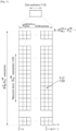
- FIG. 3 is a diagram of a structure in which an SRS is allocated per subband.
- an example in which an SRS subband is allocated for each UE based on a tree structure configured by a base station when a data transmission bandwidth corresponds to 40 RBs in the frequency domain is shown.
- the tree structure may have various numbers of levels, various SRS subband sizes, and various numbers of SRS subbands per level in accordance with configuration of the base station.
- the number of SRS subbands of a level b, which are generated from one SRS subband of an upper level, may be defined as N b
- the UEs may simultaneously transmit SRSs through multiple component carriers (CCs) or through multiple SRS subbands in one CC.
- CCs component carriers
- 5G or NR UEs support SU-MIMO and have up to four transmit antennas.
- the UEs may simultaneously transmit SRSs through multiple CCs or through multiple SRS subbands in a CC.
- a 5G or NR system may support various numerologies, variously configure SRS symbols, and enable repeated transmission of the SRS symbols.
- it is determined to support SRS antenna switching for 1Tx (in the case of UE with 1T2R), 2Tx (in the case of UE with 2T4R), and 4Tx (in the case of UE with 1T4R).
- configuration of four receive antennas for a UE is regarded as a crucial scenario and SRS antenna switching needs to be effectively supported to allow the base station to obtain channel information of all the four receive antennas considering channels satisfying UL/DL reciprocity. Therefore, the 5G or NR system requires technologies for performing and controlling SRS transmission through multiple antennas.
- the present disclosure may also be applied to other communication systems having similar technical backgrounds or channel configurations. Therefore, the present disclosure may also be applied to the other communication systems through partial modification thereof by one of ordinary skill in the art without greatly departing from the scope of the present disclosure.
- the 5G or NR system not only supports various numerologies but also supports multiple SRS transmitting OFDM symbols and an SRS symbol repetition factor. Therefore, SRS transmission counting considering the above is required.
- SRS transmission counting may be used in various ways. SRS transmission counting may be used to support antenna switching based on SRS transmission. Specifically, SRS transmission counting may be used to determine which antenna is to be used for transmission at which SRS transmission timing. In the present disclosure, a SRS transmission counting method considering a numerology of a 5G or NR system, the number of SRS transmitting OFDM symbols, a SRS symbol repetition factor, etc., will be described.
- An SRS transmission counting method considering a numerology of a 5G or NR system, the number of SRS transmitting OFDM symbols, an SRS symbol repetition factor, etc., is described herein.
- Location configuration for SRS frequency hopping may vary depending on an SRS transmission timing, and antenna selection for SRS antenna switching may also vary depending on the SRS transmission timing. Therefore, in the 5G or NR system, definition of SRS transmission counting is very significant for SRS transmission. The following needs to be considered for SRS transmission counting.
- the numerology and the number of slots need to be considered for SRS transmission counting.
- Table 1 and Table 2 define the number of slots per frame, N slot frame , ⁇ based on a numerology ⁇ supported by the 5G or NR system. Therefore, the slot number in a frame may be counted as n s , f ⁇ ⁇ 0 , ... , N slot frame , ⁇ ⁇ 1 .
- SRS transmission counting may be performed based on an SRS periodicity. In the 5G or NR system, the SRS periodicity may be defined as the number of slots.
- Table 4 defines the SRS periodicity ( T SRS ) and an offset value ( T offset ) for the 5G or NR system by using 12 bits. For example, in Table 4, when T SRS is configured to 2 slots and T offset is 0, SRS transmission is performed in an even slot, n s , f ⁇ of which is 0, 2, 4, 6...
- the number of SRS symbols and an SRS symbol repetition factor need to be used for SRS transmission counting.
- the 5G or NR system may configure the number of SRS symbols, N to be 1, 2, or 4 and transmit the SRS symbols by using consecutive symbols.
- the 5G or NR system may enable repeated transmission of the SRS symbols.
- the SRS symbol repetition factor may be configured to be r ⁇ ⁇ 1, 2, 4 ⁇ , where r ⁇ N.
- the number of SRS symbols, N, and the SRS symbol repetition factor, r may be independently configured through radio resource control (RRC) configuration or may be indirectly configured for the UE by using other signaling parameters. More specifically, influence of the number of SRS symbols and the SRS symbol repetition factor on SRS transmission counting will now be described with reference to FIG. 4 .
- RRC radio resource control
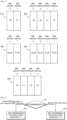
- FIG. 4 is a diagram of an SRS transmission counting method, according to an embodiment.
- a 5G or NR system may configure multiple SRS resources and use X-port SRS resources to transmit N adjacent OFDM symbols in the same slot.
- FIG. 4 shows an example of mapping between antennas and SRS symbols considering SRS antenna switching.
- d10 indicates a case in which two antennas transmit OFDM symbols by using two SRS resources.
- one SRS resource is defined for each symbol, and different antennas p0 and p1 may transmit at each SRS resource.
- d20 indicates another case in which two antennas transmit OFDM symbols by using two SRS resources.
- d30 indicates a case in which two antennas transmit OFDM symbols by using one SRS resource.
- one SRS resource is defined for each symbol and different antenna pairs (e.g., pair0 (p0, p2) and pair1 (p1, p3)) may transmit at each SRS resource.
- the antenna pairs may also be configured as pair0 (p0, p1) and pair1 (p2, p3).
- d40 indicates another case in which two antennas transmit OFDM symbols by using one SRS resource.
- the antenna pairs may also be configured as pair0 (p0, p1) and pair1 (p2, p3).
- d50 indicates a case in which four antennas transmit OFDM symbols by using four SRS resources.
- one SRS resource is defined for each symbol and different antennas p0, p1, p2, and p3 may transmit at each SRS resource. Therefore, considering SRS antenna switching as described above, the number of SRS symbols and an SRS symbol repetition factor may vary and thus SRS transmission counting is required.
- n f denotes a frame number and the other parameters are described above.
- the above-described SRS transmission counting method may provide a crucial value for determining parameters for SRS transmission. A detailed description thereof will now be provided.
- n SRS 0 , ... , N r ⁇ 1
- the frame number, n f , the slot number, n s , f ⁇ , and the SRS periodicity T SRS do not need to be configured as in Equation (1-1). More specifically, considering SRS antenna switching as illustrated in FIG. 4 and considering only transmission in one slot in the mapping structure between antennas and SRS symbols, the SRS transmission count n SRS may be calculated using only the number of SRS symbols, N, and the SRS symbol repetition factor r. Periodic or semi-persistent SRS transmission is performed in one or more slots and thus may be counted using Equation (1-1), and aperiodic SRS transmission is completed in one slot and thus may be counted using Equation (1-2). Calculation of the SRS transmission count n SRS in Equation (1-1) and Equation (1-2) may be understood as accumulative counting of used SRS resources. An operation thereof will now be described with reference to FIG. 5 .
- FIG. 5 is a diagram of an SRS transmission counting method based on an SRS transmission type, according to an embodiment.
- a different SRS transmission counting method is used based on an SRS transmission type.
- the method may proceed to step e20 and SRS transmission counting may be performed using Equation (1-1).
- the method may proceed to step e30 and SRS transmission counting may be performed using Equation (1-2).
- periodic SRS transmission may be performed by configuring a SRS periodicity T SRS and an offset value T offset through RRC as shown in Table 4.
- a method of activating or deactivating SRS transmission by using a media access control (MAC) control element (CE) when required may be considered.
- MAC media access control
- CE control element
- DCI downlink control information
- the base station needs to measure all channels for the R antennas to measure all DL channels based on UL SRSs.
- SRS antenna switching is required.
- Table 5, Table 6, and Table 7 show examples of the antenna selection method when SRS antenna switching is supported for 1Tx (in the case of UE with 1T2R), 2Tx (in the case of UE with 2T4R), and 4Tx (in the case of UE with 1T4R). It is assumed that a SRS bandwidth is divided into four SRS subbands. Frequency hopping during SRS transmission is considered. Therefore, SRS transmission is performed in one of the four SRS subbands based on the above-described SRS transmission count n SRS .
- An antenna selection method when SRS antenna switching is supported may be expressed as shown by the following equations.
- an index a(n SRS ) may be defined as follows.
- Antenna selection when SRS antenna switching is supported for 1Tx (in the case of UE with 1T2R), 2Tx (in the case of UE with 2T4R), and 4Tx (in the case of UE with 1T4R) may be performed using Equations (2) and (3).
- Efficient SRS transmission may be enabled through frequency hopping, antenna switching, etc., and improved SRS reception of the base station may be expected.
- FIG. 6 is a diagram of a UE 600, according to an embodiment.
- the UE 600 may include a transceiver 610, a memory 620, and a processor 630.
- the transceiver 610, the memory 620, and the processor 630 of the UE 600 may operate according to the above-described communication method of the UE 600.
- elements of the UE 600 are not limited to the above-mentioned elements.
- the UE 600 may include a larger or smaller number of elements compared to the above-mentioned elements.
- the transceiver 610, the memory 620, and the processor 630 may be configured as one chip.
- the transceiver 610 may transmit and receive signals to and from a base station.
- the signals may include control information and data.
- the transceiver 610 may include a radio frequency (RF) transmitter for frequency-up-converting and amplifying a signal to be transmitted, and an RF receiver for low-noise amplifying and frequency-down-converting a received signal.
- RF radio frequency
- the RF transmitter and the RF receiver are merely examples and elements of the transceiver 610 are not limited thereto.
- the transceiver 610 may receive signals through radio channels and output the signals to the processor 630, and transmit signals output from the processor 630, through radio channels.
- the memory 620 may store programs and data required to operate the UE 600. In addition, the memory 620 may store control information or data included in signals obtained by the UE 600.
- the memory 620 may include a storage medium such as readonly memory (ROM), random access memory (RAM), a hard disk, a compact disc (CD)-ROM, or a digital versatile disc (DVD), or a combination thereof.
- the processor 630 may control a series of processes to operate the UE 600.
- the processor 630 may control SRS transmission counting and control antenna selection in a case when SRS antenna switching is supported.
- FIG. 7 is a diagram of a base station 700, according to an embodiment.
- the base station 700 may include a transceiver 710, a memory 720, and a processor 730.
- the transceiver 710, the memory 720, and the processor 730 of the base station 700 may operate according to the above-described communication method of the base station 700.
- elements of the base station 700 are not limited to the above-mentioned elements.
- the base station 700 may include a larger or smaller number of elements compared to the above-mentioned elements.
- the transceiver 710, the memory 720, and the processor 730 may be configured as one chip.
- the transceiver 710 may transmit and receive signals to and from a UE.
- the signals may include control information and data.
- the transceiver 710 may include an RF transmitter for frequency-up-converting and amplifying a signal to be transmitted, and an RF receiver for low-noise amplifying and frequency-down-converting a received signal.
- the RF transmitter and the RF receiver are merely examples and elements of the transceiver 710 are not limited thereto.
- the transceiver 710 may receive signals through radio channels and output the signals to the processor 730, and transmit signals output from the processor 730, through radio channels.
- the memory 720 may store programs and data required to operate the base station 700. In addition, the memory 720 may store control information or data included in signals obtained by the base station 700.
- the memory 720 may include a storage medium such as ROM, RAM, a hard disk, a CD-ROM, or a DVD, or a combination thereof.
- the processor 730 may control a series of processes to operate the base station 700.
- the processor 730 may control SRS transmission counting and control antenna selection in a case when SRS antenna switching is supported.
- Various embodiments of the present disclosure may be implemented by software including an instruction stored in a machine-readable storage media readable by a machine (e.g., a computer).
- the machine may be a device that calls the instruction from the machine-readable storage media and operates depending on the called instruction and may include the electronic device.
- the processor may perform a function corresponding to the instruction directly or using other components under the control of the processor.
- the instruction may include a code generated or executed by a compiler or an interpreter.
- the machine-readable storage media may be provided in the form of non-transitory storage media.
- non-transitory is a limitation of the medium itself (i.e., tangible, not a signal) as opposed to a limitation on data storage persistency.
- the method according to various embodiments disclosed in the present disclosure may be provided as a part of a computer program product.
- the computer program product may be traded between a seller and a buyer as a product.
- the computer program product may be distributed in the form of machine-readable storage medium (e.g., a compact disc read only memory (CD-ROM)) or may be distributed only through an application store (e.g., a Play Store TM ).
- an application store e.g., a Play Store TM
- at least a portion of the computer program product may be temporarily stored or generated in a storage medium such as a memory of a manufacturer's server, an application store's server, or a relay server.
- Each component may include at least one of the above components, and a portion of the above sub-components may be omitted, or additional other sub-components may be further included.
- some components may be integrated in one component and may perform the same or similar functions performed by each corresponding components prior to the integration. Operations performed by a module, a programming, or other components according to various embodiments of the present disclosure may be executed sequentially, in parallel, repeatedly, or in a heuristic method. Also, at least some operations may be executed in different sequences, omitted, or other operations may be added.
Landscapes
- Engineering & Computer Science (AREA)
- Signal Processing (AREA)
- Computer Networks & Wireless Communication (AREA)
- Mobile Radio Communication Systems (AREA)
- Radar Systems Or Details Thereof (AREA)
- Radio Relay Systems (AREA)
Claims (8)
- Procédé de transmission d'un signal de référence de sondage, SRS, le procédé exécuté par un équipement utilisateur (600) dans un système de communication sans fil prenant en charge des ports d'antenne multiples et une pluralité de numérologies, le procédé comprenant :identifier si une transmission SRS périodique ou une transmission SRS semi-persistante est configurée ;calculer,dans le cas où la transmission SRS périodique ou la transmission SRS semi-persistante est configurée, un compte de transmission SRS sur la base d'un nombre de créneaux dans une trame pour une numérologie de la pluralité de numérologies, un nombre de créneaux par trame pour la numérologie, une périodicité SRS, un nombre de symboles SRS, un facteur de répétition SRS et un nombre de trame système, etidentifier une position de fréquence pour le SRS mappé à au moins un port d'antenne des ports d'antenne multiples sur la base du compte de transmission SRS ; ettransmettre le SRS, en utilisant un saut de fréquence sur la base de la position de fréquence pour le SRS mappé à l'au moins un port d'antenne.
- Procédé selon la revendication 1, où une configuration pour la transmission SRS périodique du SRS ou une configuration pour la transmission SRS semi-persistante du SRS est reçue, d'une station de base (700).
- Procédé selon la revendication 1, où dans le cas où la transmission SRS périodique est configurée, une configuration pour la périodicité SRS et un décalage de créneau sont en outre reçus, d'une station de base (700), par une signalisation de couche supérieure, et au moins un créneau pour le SRS est déterminé sur la base de la périodicité SRS et du décalage de créneau.
- Procédé selon la revendication 1, où le nombre de symboles SRS est de 1, 2, ou 4.
- Équipement utilisateur (600) pour transmettre un signal de référence de sondage, SRS, dans un système de communication sans fil prenant en charge des ports d'antenne multiples et une pluralité de numérologies, l'équipement utilisateur comprenant :un émetteur-récepteur (610) ;au moins une mémoire (620) stockant un programme pour transmettre le SRS ; etau moins un processeur (630) configuré pour :identifier si une transmission SRS périodique ou une transmission SRS semi-persistante est configurée ;calculer,dans le cas où la transmission SRS périodique ou la transmission SRS semi-persistante est configurée, un compte de transmission SRS sur la base d'un nombre de créneaux dans une trame pour une numérologie de la pluralité de numérologies, d'un nombre de créneaux par trame pour la numérologie, d'une périodicité SRS, d'un nombre de symboles SRS, d'un facteur de répétition SRS et d'un nombre de trame système, etidentifier une position de fréquence pour le SRS mappé à au moins un port d'antenne des ports d'antenne multiples sur la base du compte de transmission SRS ; ettransmettre le SRS, en utilisant un saut de fréquence sur la base de la position de fréquence pour le SRS mappé à l'au moins un port d'antenne.
- Équipement utilisateur selon la revendication 5, où l'au moins un processeur est en outre configuré pour recevoir une configuration pour la transmission SRS périodique du SRS ou une configuration pour la transmission SRS semi-persistante du SRS d'une station de base (700).
- Équipement utilisateur selon la revendication 5, où dans le cas où la transmission SRS périodique est configurée, l'au moins un processeur est en outre configuré pour :recevoir une configuration pour la périodicité SRS et un décalage de créneau, d'une station de base (700), par une signalisation de couche supérieure ;déterminer au moins un créneau pour le SRS sur la base de la périodicité SRS et du décalage de créneau.
- Équipement utilisateur selon la revendication 5, où le nombre de symboles SRS est de 1, 2 ou 4.
Priority Applications (1)
| Application Number | Priority Date | Filing Date | Title |
|---|---|---|---|
| EP24195667.1A EP4443809A3 (fr) | 2017-11-17 | 2018-11-19 | Procédé et appareil d'émission et de réception de signal de référence dans un système de communication sans fil |
Applications Claiming Priority (3)
| Application Number | Priority Date | Filing Date | Title |
|---|---|---|---|
| KR20170154299 | 2017-11-17 | ||
| KR1020170158917A KR102410474B1 (ko) | 2017-11-17 | 2017-11-24 | 무선 통신 시스템에서 기준 신호 송수신 방법 및 장치 |
| PCT/KR2018/014195 WO2019098788A1 (fr) | 2017-11-17 | 2018-11-19 | Procédé et appareil de transmission et de réception d'un signal de référence dans un système de communication sans fil |
Related Child Applications (2)
| Application Number | Title | Priority Date | Filing Date |
|---|---|---|---|
| EP24195667.1A Division-Into EP4443809A3 (fr) | 2017-11-17 | 2018-11-19 | Procédé et appareil d'émission et de réception de signal de référence dans un système de communication sans fil |
| EP24195667.1A Division EP4443809A3 (fr) | 2017-11-17 | 2018-11-19 | Procédé et appareil d'émission et de réception de signal de référence dans un système de communication sans fil |
Publications (3)
| Publication Number | Publication Date |
|---|---|
| EP3656076A1 EP3656076A1 (fr) | 2020-05-27 |
| EP3656076A4 EP3656076A4 (fr) | 2020-07-22 |
| EP3656076B1 true EP3656076B1 (fr) | 2024-10-02 |
Family
ID=66679530
Family Applications (2)
| Application Number | Title | Priority Date | Filing Date |
|---|---|---|---|
| EP18879475.4A Active EP3656076B1 (fr) | 2017-11-17 | 2018-11-19 | Procédé et appareil de transmission et de réception d'un signal de référence dans un système de communication sans fil |
| EP24195667.1A Pending EP4443809A3 (fr) | 2017-11-17 | 2018-11-19 | Procédé et appareil d'émission et de réception de signal de référence dans un système de communication sans fil |
Family Applications After (1)
| Application Number | Title | Priority Date | Filing Date |
|---|---|---|---|
| EP24195667.1A Pending EP4443809A3 (fr) | 2017-11-17 | 2018-11-19 | Procédé et appareil d'émission et de réception de signal de référence dans un système de communication sans fil |
Country Status (5)
| Country | Link |
|---|---|
| US (3) | US11349618B2 (fr) |
| EP (2) | EP3656076B1 (fr) |
| KR (2) | KR102410474B1 (fr) |
| CN (2) | CN117220847A (fr) |
| AU (2) | AU2018367796B2 (fr) |
Families Citing this family (11)
| Publication number | Priority date | Publication date | Assignee | Title |
|---|---|---|---|---|
| JP2019145867A (ja) * | 2016-07-05 | 2019-08-29 | シャープ株式会社 | 基地局装置、端末装置および通信方法 |
| WO2018199696A1 (fr) * | 2017-04-27 | 2018-11-01 | 엘지전자 주식회사 | Procédé d'émission de srs et terminal correspondant |
| WO2019205178A1 (fr) * | 2018-04-28 | 2019-10-31 | 华为技术有限公司 | Procédé de transmission d'un signal de référence de détection et dispositif terminal |
| KR102636644B1 (ko) * | 2020-03-02 | 2024-02-13 | 주식회사 케이티 | 기지국의 하향링크 빔포밍 장치 및 방법 |
| KR20210141229A (ko) | 2020-05-15 | 2021-11-23 | 삼성전자주식회사 | 전자 장치 및 전자 장치에서 기준 신호를 전송하는 방법 |
| CN114337946B (zh) * | 2020-09-29 | 2025-04-29 | 维沃移动通信有限公司 | 探测参考信号配置方法、终端及网络侧设备 |
| EP4068642A1 (fr) * | 2021-04-01 | 2022-10-05 | QUALCOMM Incorporated | Indication de commutation d'antenne de transmission de liaison montante |
| US20240121053A1 (en) * | 2021-04-06 | 2024-04-11 | Nokia Technologies Oy | Uplink (ul) sounding reference signal (srs) resource configuration |
| US12574171B2 (en) * | 2022-06-14 | 2026-03-10 | Qualcomm Incorporated | Waveform switching for downlink transmissions |
| KR20250164727A (ko) * | 2023-04-05 | 2025-11-25 | 퀄컴 인코포레이티드 | 분산형 안테나 포트 맵핑을 위한 srs(sounding reference signal) 주파수 홉핑 |
| CN120956398A (zh) * | 2025-08-13 | 2025-11-14 | 深圳传音控股股份有限公司 | 处理方法、通信设备及存储介质 |
Family Cites Families (13)
| Publication number | Priority date | Publication date | Assignee | Title |
|---|---|---|---|---|
| US7801521B2 (en) * | 2005-05-18 | 2010-09-21 | Telefonaktiebolaget L M Ericsson (Publ) | System and method for communicating with aircraft through cellular base station towers |
| US20090180451A1 (en) | 2008-01-10 | 2009-07-16 | Comsys Communication & Signal Processing Ltd. | Apparatus for and method of coordinating transmission and reception opportunities in a communications device incorporating multiple radios |
| KR101639810B1 (ko) * | 2009-01-13 | 2016-07-25 | 엘지전자 주식회사 | 무선통신 시스템에서 사운딩 참조신호의 전송방법 |
| CN106850023B (zh) | 2009-03-22 | 2020-09-15 | Lg电子株式会社 | 使用多个天线的信道探测方法以及用于其的装置 |
| KR101128817B1 (ko) * | 2009-05-15 | 2012-03-23 | 엘지전자 주식회사 | 무선 통신 시스템에서 사운딩 참조 신호 송신 방법 및 이를 위한 장치 |
| US8737335B2 (en) | 2009-06-19 | 2014-05-27 | Kddi Corporation | Reference signal transmission scheduling device and reference signal transmission scheduling method |
| CN102577523A (zh) * | 2009-09-21 | 2012-07-11 | Lg电子株式会社 | 在无线通信系统中发送探测参考信号的方法和装置 |
| EP2375617A1 (fr) | 2010-04-08 | 2011-10-12 | HTC Corporation | Procédé de gestion de transmission du signal de référence utilisé durant l'estimation du canal de transmission |
| KR20110119502A (ko) | 2010-04-26 | 2011-11-02 | 삼성전자주식회사 | 다중 안테나 전송 기법을 사용하는 상향링크 무선 통신 시스템에서의 사운딩 레퍼런스 신호 전송 방법 |
| KR20110126034A (ko) * | 2010-05-14 | 2011-11-22 | 엘지전자 주식회사 | 무선 통신 시스템에서 비주기적 사운딩 참조 신호 전송 방법 및 장치 |
| EP3282627B1 (fr) | 2015-04-10 | 2020-07-08 | LG Electronics Inc. | Procédé et appareil pour contrôler la transmission d'un signal de référence de sondage dans un système d'accès sans fil prenant en charge la communication de type machine |
| ES2914649T3 (es) * | 2016-04-01 | 2022-06-15 | Huawei Tech Co Ltd | Sistema y método de conmutación, transmisión y mejoras SRS |
| US10560851B2 (en) * | 2017-01-13 | 2020-02-11 | Samsung Electronics Co., Ltd. | Method and apparatus for uplink beam management in next generation wireless systems |
-
2017
- 2017-11-24 KR KR1020170158917A patent/KR102410474B1/ko active Active
-
2018
- 2018-11-19 CN CN202311200281.0A patent/CN117220847A/zh active Pending
- 2018-11-19 EP EP18879475.4A patent/EP3656076B1/fr active Active
- 2018-11-19 CN CN201880070731.XA patent/CN111295856B/zh active Active
- 2018-11-19 AU AU2018367796A patent/AU2018367796B2/en active Active
- 2018-11-19 EP EP24195667.1A patent/EP4443809A3/fr active Pending
-
2020
- 2020-05-26 US US16/883,682 patent/US11349618B2/en active Active
-
2022
- 2022-05-27 US US17/826,424 patent/US11791963B2/en active Active
- 2022-06-14 KR KR1020220072357A patent/KR102527280B1/ko active Active
-
2023
- 2023-04-12 AU AU2023202253A patent/AU2023202253B2/en active Active
- 2023-09-14 US US18/467,139 patent/US12192138B2/en active Active
Also Published As
| Publication number | Publication date |
|---|---|
| US11791963B2 (en) | 2023-10-17 |
| AU2018367796B2 (en) | 2023-01-19 |
| US11349618B2 (en) | 2022-05-31 |
| KR20220086540A (ko) | 2022-06-23 |
| KR20190056929A (ko) | 2019-05-27 |
| AU2023202253A1 (en) | 2023-05-04 |
| US20240007245A1 (en) | 2024-01-04 |
| KR102527280B1 (ko) | 2023-05-02 |
| EP3656076A4 (fr) | 2020-07-22 |
| US20220294586A1 (en) | 2022-09-15 |
| EP4443809A3 (fr) | 2024-11-13 |
| AU2023202253B2 (en) | 2024-06-20 |
| US12192138B2 (en) | 2025-01-07 |
| US20200287684A1 (en) | 2020-09-10 |
| CN111295856A (zh) | 2020-06-16 |
| KR102410474B1 (ko) | 2022-06-20 |
| CN117220847A (zh) | 2023-12-12 |
| EP4443809A2 (fr) | 2024-10-09 |
| EP3656076A1 (fr) | 2020-05-27 |
| AU2018367796A1 (en) | 2020-02-20 |
| CN111295856B (zh) | 2023-10-03 |
Similar Documents
| Publication | Publication Date | Title |
|---|---|---|
| US12192138B2 (en) | Method and apparatus for transmitting and receiving reference signal in wireless communication system | |
| US10666408B2 (en) | Method and apparatus for transmitting and receiving reference signal in wireless communication system | |
| US11683141B2 (en) | Method and apparatus for configuring demodulation reference signal information in wireless cellular communication system | |
| US11470603B2 (en) | Method and apparatus for transmitting downlink control information in wireless communication system | |
| US11595181B2 (en) | Method and apparatus for transmitting different uplink control information in wireless communication system | |
| US10880879B2 (en) | Method and apparatus for transmitting downlink control information in wireless communication system | |
| US11129088B2 (en) | Method and apparatus for transmitting downlink control information in wireless communication system | |
| US12470349B2 (en) | Method and apparatus for configuring demodulation reference signal information in wireless cellular communication system | |
| EP4221041B1 (fr) | Procédé et appareil de transmission d'informations de commande de liaison descendante dans un système de communication sans fil |
Legal Events
| Date | Code | Title | Description |
|---|---|---|---|
| STAA | Information on the status of an ep patent application or granted ep patent |
Free format text: STATUS: THE INTERNATIONAL PUBLICATION HAS BEEN MADE |
|
| PUAI | Public reference made under article 153(3) epc to a published international application that has entered the european phase |
Free format text: ORIGINAL CODE: 0009012 |
|
| STAA | Information on the status of an ep patent application or granted ep patent |
Free format text: STATUS: REQUEST FOR EXAMINATION WAS MADE |
|
| 17P | Request for examination filed |
Effective date: 20200220 |
|
| AK | Designated contracting states |
Kind code of ref document: A1 Designated state(s): AL AT BE BG CH CY CZ DE DK EE ES FI FR GB GR HR HU IE IS IT LI LT LU LV MC MK MT NL NO PL PT RO RS SE SI SK SM TR |
|
| AX | Request for extension of the european patent |
Extension state: BA ME |
|
| A4 | Supplementary search report drawn up and despatched |
Effective date: 20200623 |
|
| RIC1 | Information provided on ipc code assigned before grant |
Ipc: H04L 5/00 20060101AFI20200617BHEP |
|
| DAV | Request for validation of the european patent (deleted) | ||
| DAX | Request for extension of the european patent (deleted) | ||
| STAA | Information on the status of an ep patent application or granted ep patent |
Free format text: STATUS: EXAMINATION IS IN PROGRESS |
|
| 17Q | First examination report despatched |
Effective date: 20210304 |
|
| GRAP | Despatch of communication of intention to grant a patent |
Free format text: ORIGINAL CODE: EPIDOSNIGR1 |
|
| STAA | Information on the status of an ep patent application or granted ep patent |
Free format text: STATUS: GRANT OF PATENT IS INTENDED |
|
| INTG | Intention to grant announced |
Effective date: 20231206 |
|
| GRAJ | Information related to disapproval of communication of intention to grant by the applicant or resumption of examination proceedings by the epo deleted |
Free format text: ORIGINAL CODE: EPIDOSDIGR1 |
|
| STAA | Information on the status of an ep patent application or granted ep patent |
Free format text: STATUS: EXAMINATION IS IN PROGRESS |
|
| GRAP | Despatch of communication of intention to grant a patent |
Free format text: ORIGINAL CODE: EPIDOSNIGR1 |
|
| STAA | Information on the status of an ep patent application or granted ep patent |
Free format text: STATUS: GRANT OF PATENT IS INTENDED |
|
| INTC | Intention to grant announced (deleted) | ||
| INTG | Intention to grant announced |
Effective date: 20240507 |
|
| GRAS | Grant fee paid |
Free format text: ORIGINAL CODE: EPIDOSNIGR3 |
|
| GRAA | (expected) grant |
Free format text: ORIGINAL CODE: 0009210 |
|
| STAA | Information on the status of an ep patent application or granted ep patent |
Free format text: STATUS: THE PATENT HAS BEEN GRANTED |
|
| AK | Designated contracting states |
Kind code of ref document: B1 Designated state(s): AL AT BE BG CH CY CZ DE DK EE ES FI FR GB GR HR HU IE IS IT LI LT LU LV MC MK MT NL NO PL PT RO RS SE SI SK SM TR |
|
| REG | Reference to a national code |
Ref country code: GB Ref legal event code: FG4D |
|
| REG | Reference to a national code |
Ref country code: CH Ref legal event code: EP |
|
| REG | Reference to a national code |
Ref country code: IE Ref legal event code: FG4D Ref country code: NL Ref legal event code: FP |
|
| REG | Reference to a national code |
Ref country code: DE Ref legal event code: R096 Ref document number: 602018075063 Country of ref document: DE |
|
| REG | Reference to a national code |
Ref country code: LT Ref legal event code: MG9D |
|
| REG | Reference to a national code |
Ref country code: AT Ref legal event code: MK05 Ref document number: 1729222 Country of ref document: AT Kind code of ref document: T Effective date: 20241002 |
|
| PG25 | Lapsed in a contracting state [announced via postgrant information from national office to epo] |
Ref country code: PT Free format text: LAPSE BECAUSE OF FAILURE TO SUBMIT A TRANSLATION OF THE DESCRIPTION OR TO PAY THE FEE WITHIN THE PRESCRIBED TIME-LIMIT Effective date: 20250203 Ref country code: IS Free format text: LAPSE BECAUSE OF FAILURE TO SUBMIT A TRANSLATION OF THE DESCRIPTION OR TO PAY THE FEE WITHIN THE PRESCRIBED TIME-LIMIT Effective date: 20250202 Ref country code: HR Free format text: LAPSE BECAUSE OF FAILURE TO SUBMIT A TRANSLATION OF THE DESCRIPTION OR TO PAY THE FEE WITHIN THE PRESCRIBED TIME-LIMIT Effective date: 20241002 |
|
| PG25 | Lapsed in a contracting state [announced via postgrant information from national office to epo] |
Ref country code: FI Free format text: LAPSE BECAUSE OF FAILURE TO SUBMIT A TRANSLATION OF THE DESCRIPTION OR TO PAY THE FEE WITHIN THE PRESCRIBED TIME-LIMIT Effective date: 20241002 |
|
| PG25 | Lapsed in a contracting state [announced via postgrant information from national office to epo] |
Ref country code: BG Free format text: LAPSE BECAUSE OF FAILURE TO SUBMIT A TRANSLATION OF THE DESCRIPTION OR TO PAY THE FEE WITHIN THE PRESCRIBED TIME-LIMIT Effective date: 20241002 |
|
| PG25 | Lapsed in a contracting state [announced via postgrant information from national office to epo] |
Ref country code: ES Free format text: LAPSE BECAUSE OF FAILURE TO SUBMIT A TRANSLATION OF THE DESCRIPTION OR TO PAY THE FEE WITHIN THE PRESCRIBED TIME-LIMIT Effective date: 20241002 |
|
| PG25 | Lapsed in a contracting state [announced via postgrant information from national office to epo] |
Ref country code: NO Free format text: LAPSE BECAUSE OF FAILURE TO SUBMIT A TRANSLATION OF THE DESCRIPTION OR TO PAY THE FEE WITHIN THE PRESCRIBED TIME-LIMIT Effective date: 20250102 |
|
| PG25 | Lapsed in a contracting state [announced via postgrant information from national office to epo] |
Ref country code: AT Free format text: LAPSE BECAUSE OF FAILURE TO SUBMIT A TRANSLATION OF THE DESCRIPTION OR TO PAY THE FEE WITHIN THE PRESCRIBED TIME-LIMIT Effective date: 20241002 Ref country code: LV Free format text: LAPSE BECAUSE OF FAILURE TO SUBMIT A TRANSLATION OF THE DESCRIPTION OR TO PAY THE FEE WITHIN THE PRESCRIBED TIME-LIMIT Effective date: 20241002 Ref country code: GR Free format text: LAPSE BECAUSE OF FAILURE TO SUBMIT A TRANSLATION OF THE DESCRIPTION OR TO PAY THE FEE WITHIN THE PRESCRIBED TIME-LIMIT Effective date: 20250103 |
|
| PG25 | Lapsed in a contracting state [announced via postgrant information from national office to epo] |
Ref country code: PL Free format text: LAPSE BECAUSE OF FAILURE TO SUBMIT A TRANSLATION OF THE DESCRIPTION OR TO PAY THE FEE WITHIN THE PRESCRIBED TIME-LIMIT Effective date: 20241002 Ref country code: CZ Free format text: LAPSE BECAUSE OF FAILURE TO SUBMIT A TRANSLATION OF THE DESCRIPTION OR TO PAY THE FEE WITHIN THE PRESCRIBED TIME-LIMIT Effective date: 20241002 |
|
| PG25 | Lapsed in a contracting state [announced via postgrant information from national office to epo] |
Ref country code: RS Free format text: LAPSE BECAUSE OF FAILURE TO SUBMIT A TRANSLATION OF THE DESCRIPTION OR TO PAY THE FEE WITHIN THE PRESCRIBED TIME-LIMIT Effective date: 20250102 |
|
| REG | Reference to a national code |
Ref country code: CH Ref legal event code: PL |
|
| PG25 | Lapsed in a contracting state [announced via postgrant information from national office to epo] |
Ref country code: SM Free format text: LAPSE BECAUSE OF FAILURE TO SUBMIT A TRANSLATION OF THE DESCRIPTION OR TO PAY THE FEE WITHIN THE PRESCRIBED TIME-LIMIT Effective date: 20241002 |
|
| REG | Reference to a national code |
Ref country code: DE Ref legal event code: R097 Ref document number: 602018075063 Country of ref document: DE |
|
| PG25 | Lapsed in a contracting state [announced via postgrant information from national office to epo] |
Ref country code: MC Free format text: LAPSE BECAUSE OF FAILURE TO SUBMIT A TRANSLATION OF THE DESCRIPTION OR TO PAY THE FEE WITHIN THE PRESCRIBED TIME-LIMIT Effective date: 20241002 |
|
| PG25 | Lapsed in a contracting state [announced via postgrant information from national office to epo] |
Ref country code: DK Free format text: LAPSE BECAUSE OF FAILURE TO SUBMIT A TRANSLATION OF THE DESCRIPTION OR TO PAY THE FEE WITHIN THE PRESCRIBED TIME-LIMIT Effective date: 20241002 |
|
| PG25 | Lapsed in a contracting state [announced via postgrant information from national office to epo] |
Ref country code: LU Free format text: LAPSE BECAUSE OF NON-PAYMENT OF DUE FEES Effective date: 20241119 |
|
| REG | Reference to a national code |
Ref country code: CH Ref legal event code: PL |
|
| PG25 | Lapsed in a contracting state [announced via postgrant information from national office to epo] |
Ref country code: EE Free format text: LAPSE BECAUSE OF FAILURE TO SUBMIT A TRANSLATION OF THE DESCRIPTION OR TO PAY THE FEE WITHIN THE PRESCRIBED TIME-LIMIT Effective date: 20241002 |
|
| PG25 | Lapsed in a contracting state [announced via postgrant information from national office to epo] |
Ref country code: CH Free format text: LAPSE BECAUSE OF NON-PAYMENT OF DUE FEES Effective date: 20241130 |
|
| PG25 | Lapsed in a contracting state [announced via postgrant information from national office to epo] |
Ref country code: RO Free format text: LAPSE BECAUSE OF FAILURE TO SUBMIT A TRANSLATION OF THE DESCRIPTION OR TO PAY THE FEE WITHIN THE PRESCRIBED TIME-LIMIT Effective date: 20241002 |
|
| PG25 | Lapsed in a contracting state [announced via postgrant information from national office to epo] |
Ref country code: SK Free format text: LAPSE BECAUSE OF FAILURE TO SUBMIT A TRANSLATION OF THE DESCRIPTION OR TO PAY THE FEE WITHIN THE PRESCRIBED TIME-LIMIT Effective date: 20241002 |
|
| PLBE | No opposition filed within time limit |
Free format text: ORIGINAL CODE: 0009261 |
|
| STAA | Information on the status of an ep patent application or granted ep patent |
Free format text: STATUS: NO OPPOSITION FILED WITHIN TIME LIMIT |
|
| REG | Reference to a national code |
Ref country code: BE Ref legal event code: MM Effective date: 20241130 |
|
| PG25 | Lapsed in a contracting state [announced via postgrant information from national office to epo] |
Ref country code: SE Free format text: LAPSE BECAUSE OF FAILURE TO SUBMIT A TRANSLATION OF THE DESCRIPTION OR TO PAY THE FEE WITHIN THE PRESCRIBED TIME-LIMIT Effective date: 20241002 |
|
| 26N | No opposition filed |
Effective date: 20250703 |
|
| PG25 | Lapsed in a contracting state [announced via postgrant information from national office to epo] |
Ref country code: BE Free format text: LAPSE BECAUSE OF NON-PAYMENT OF DUE FEES Effective date: 20241130 |
|
| PG25 | Lapsed in a contracting state [announced via postgrant information from national office to epo] |
Ref country code: IE Free format text: LAPSE BECAUSE OF NON-PAYMENT OF DUE FEES Effective date: 20241119 |
|
| PGFP | Annual fee paid to national office [announced via postgrant information from national office to epo] |
Ref country code: NL Payment date: 20251020 Year of fee payment: 8 |
|
| PGFP | Annual fee paid to national office [announced via postgrant information from national office to epo] |
Ref country code: DE Payment date: 20251020 Year of fee payment: 8 |
|
| PGFP | Annual fee paid to national office [announced via postgrant information from national office to epo] |
Ref country code: GB Payment date: 20251023 Year of fee payment: 8 |
|
| PGFP | Annual fee paid to national office [announced via postgrant information from national office to epo] |
Ref country code: IT Payment date: 20251021 Year of fee payment: 8 |
|
| PGFP | Annual fee paid to national office [announced via postgrant information from national office to epo] |
Ref country code: FR Payment date: 20251021 Year of fee payment: 8 |
|
| PG25 | Lapsed in a contracting state [announced via postgrant information from national office to epo] |
Ref country code: HU Free format text: LAPSE BECAUSE OF FAILURE TO SUBMIT A TRANSLATION OF THE DESCRIPTION OR TO PAY THE FEE WITHIN THE PRESCRIBED TIME-LIMIT; INVALID AB INITIO Effective date: 20181119 |
|
| PG25 | Lapsed in a contracting state [announced via postgrant information from national office to epo] |
Ref country code: CY Free format text: LAPSE BECAUSE OF FAILURE TO SUBMIT A TRANSLATION OF THE DESCRIPTION OR TO PAY THE FEE WITHIN THE PRESCRIBED TIME-LIMIT; INVALID AB INITIO Effective date: 20181119 |