EP3656258B1 - Boîte pour colis - Google Patents
Boîte pour colis Download PDFInfo
- Publication number
- EP3656258B1 EP3656258B1 EP19205833.7A EP19205833A EP3656258B1 EP 3656258 B1 EP3656258 B1 EP 3656258B1 EP 19205833 A EP19205833 A EP 19205833A EP 3656258 B1 EP3656258 B1 EP 3656258B1
- Authority
- EP
- European Patent Office
- Prior art keywords
- receiving device
- parcel box
- parcel
- box according
- designed
- Prior art date
- Legal status (The legal status is an assumption and is not a legal conclusion. Google has not performed a legal analysis and makes no representation as to the accuracy of the status listed.)
- Active
Links
Images




Classifications
-
- A—HUMAN NECESSITIES
- A47—FURNITURE; DOMESTIC ARTICLES OR APPLIANCES; COFFEE MILLS; SPICE MILLS; SUCTION CLEANERS IN GENERAL
- A47G—HOUSEHOLD OR TABLE EQUIPMENT
- A47G29/00—Supports, holders, or containers for household use, not provided for in groups A47G1/00-A47G27/00 or A47G33/00
- A47G29/14—Deposit receptacles for food, e.g. breakfast, milk, or large parcels; Similar receptacles for food or large parcels with appliances for preventing unauthorised removal of the deposited articles, i.e. food or large parcels
- A47G29/20—Deposit receptacles for food, e.g. breakfast, milk, or large parcels; Similar receptacles for food or large parcels with appliances for preventing unauthorised removal of the deposited articles, i.e. food or large parcels with appliances for preventing unauthorised removal of the deposited articles
- A47G29/22—Deposit receptacles for food, e.g. breakfast, milk, or large parcels; Similar receptacles for food or large parcels with appliances for preventing unauthorised removal of the deposited articles, i.e. food or large parcels with appliances for preventing unauthorised removal of the deposited articles having rotatable or reciprocable parts
Definitions
- the invention relates to a parcel box that is suitable, among other things, for the delivery, collection, storage or acceptance of shipping parcels.
- Parcel boxes are particularly suitable as an additional acceptance device for parcels in addition to the usual mailbox in the household or commercial environment.
- WO 2006/015307 A2 discloses a package collection device that is intended to enable barrier-free operation for disabled people.
- the pick-up device can be actuated with little force and a maximum actuation height using a lever mechanism, springs and weights.
- DE 10 2006 039 002 A1 discloses a collection container for collecting parcels with a deposit opening, an acceptance device and a storage space.
- the previously known parcel acceptance devices are not optimally suited for direct loading by a parcel deliverer while at the same time being used in the open air in a weather-resistant manner.
- EP 1 252 845 A1 discloses an acceptance device for data carriers with electronic chips.
- the device includes a scanner for contactless electronic recognition of specific objects, regardless of their position in the acceptance device.
- the device is powered by a stepper motor and will only accept items if a valid signal from a chip on the item is detected.
- a common problem when dropping a package into a package delivery box is that the operator must first open the device or activate a mechanism before the package can be inserted into an appropriate device.
- the object of the present invention is to provide an improved parcel box.
- the invention solves the problem with the features of the main claim.
- the disclosed parcel box is suitable for delivering one or more parcels to an addressee. Parcels can also be collected for shipping. The parcels are stored safely in the parcel box and are protected from the weather.
- the parcel box disclosed comprises a receiving device and a collection container.
- the receiving device is pivotable. One or more packages can be placed in the receiving device. In the basic position, the receiving device is already accessible from the outside for loading.
- the package is placed on a storage area of the receiving device.
- An approaching person can simply place a package in the receiving device without operating a mechanism.
- the basic position of the receiving device is also the loading position.
- the basic position describes the equilibrium position of the recording device. Without external influence, the recording device remains in the basic position, so that loading is easily possible at any time. In the basic position, the recording device should remain in particular before and after actuation.
- the parcel box has restoring means, by means of which the receiving device pivots back into the basic position on its own.
- the receiving device After loading the receiving device, the receiving device can be pivoted into a tilted position.
- the rotation of the receiving device allows the parcel to slide inside the parcel box into the collection container.
- the pivoting movement can be a rotation about a predetermined axis.
- a more complex pivoting movement can be implemented using multi-body kinematics.
- a picked-up package preferably slips out of the pick-up device into the collection container due to its own weight.
- the parcels picked up are safely stored in the collection container.
- the packages can be removed at a later point in time by means of a removal access.
- the parcel box advantageously includes a lockable door.
- the parcel box is advantageously also secured against unauthorized access to the parcels.
- the receiving device is preferably used by the operator between the loading position and the tilting position panned.
- the receiving device has a corresponding handle on the front side.
- the recording device can be operated with one hand. This is particularly advantageous for the delivery of several parcels in a row.
- a particular advantage of the disclosed parcel box results from the basic position of the receiving device.
- the parcel box is designed to be loaded without prior operation.
- the receiving device is preferably open at the front.
- the receiving device preferably forms a feed chute that is open towards the front.
- a deliverer can insert a parcel directly into the parcel box in its basic position.
- the parcel box can be placed inside a living area or outside of a living area.
- the parcel box is particularly suitable for outdoor use. Due to its design, no rainwater collects in the receiving device. Incoming water can flow off to the front.
- FIG 1 shows an embodiment of a parcel box (100).
- the parcel box (100) comprises a receiving device (200) and a collection container (300).
- the receiving device (200) is designed to receive a package (P).
- the receiving device (200) comprises a storage area (205).
- the receiving device (200) forms a feed shaft (210).
- the feed shaft (210) is formed by one or more walls (201).
- the feed chute (210) is preferably cuboid. One or more side faces of the cuboid shape can be open.
- the dimensions of the receiving device (200) are preferably based on the usual standard package sizes.
- the dimensions of the feed chute preferably offer a few centimeters of play compared to a maximum standard package size. This design enables a compact and space-saving design.
- An embodiment of the receiving device with a side wall and/or a top wall is particularly advantageous.
- the walls (201) form a well-defined shaft. Canting of the package is prevented.
- the parcel box (100) also includes an integrated collection container (300).
- the collection container (300) is designed to keep the stored packages safe.
- the dimensions of the collection container (300) depend on the desired application.
- the collection container (300) is dimensioned in such a way that there is space for several packages and parcels.
- the parcel box (100) preferably has dimensions of 0.5 m to 1.5 m in width and/or depth.
- the parcel box is preferably 1m to 2.5m high.
- the receiving device (200) is preferably designed for specific package sizes.
- Preferred package sizes are 0.35m x 0.25m x 0.1m packages, 0.6m x 0.3m x 1.5m packages, 0.6m x 0.3m x 0.15m packages, 1.2m packages ⁇ 0.6m ⁇ 0.6m and/or packages up to 1.2m ⁇ 0.6m ⁇ 0.6m.
- the parcel box (100), in particular the collection container (300), is preferably dimensioned sufficiently deep so that several parcels can be stored one behind the other in the depth of the parcel box.
- the parcel box (100) preferably includes a removal access (310).
- the removal access (310) is preferably designed as a door.
- the door can be lockable.
- a lockable door is particularly advantageous for access control to the stored packages.
- the parcel box (100) includes rollers (400).
- the parcel box (100) is mobile in this embodiment.
- the parcel box (100) can be placed anywhere inside or outside of a building.
- the parcel box (100) can have feet.
- the rollers can be designed so that they can be braked.
- the parcel box (100) is also preferably designed to be weatherproof.
- the parcel box (100) advantageously has a roof (500).
- the roof (500) preferably has a gradient. This allows rainwater to drain away.
- the roof (500) preferably protrudes in at least one direction over the body of the parcel box.
- the projection of the roof over the base of the parcel box is advantageous in order to offer additional protection against rain and the effects of the weather.
- the parcel box (100) is protected from rain by a shield, particularly on the front, i.e. the side from which the receiving device (200) can be loaded.
- the receiving device (200) advantageously comprises a handle (220).
- the receiving device (200) can be pivoted on the handle (220).
- the receiving device can have a mechanical and/or electrical drive.
- the pivoting movement of the receiving device (200) can be supported by a spring and/or a drive.
- the parcel box (100) advantageously includes restoring means for restoring the receiving device to the basic position, i.e. the loading position (S1).
- restoring means act preferably in the direction of the basic position.
- Means for supporting the tilting movement can also act in certain areas along the pivoting movement. It's special advantageous to let the restoring means and/or the tilting support means act with different intensity in certain areas of the pivoting movement. This can be realized in particular by using suitable lever kinematics.
- the pivoting movement can in particular be supported in a controllable manner.
- the parcel box (100) includes a lock (250) for the receiving device (200).
- the receiving device (200) can be locked with a lock (250).
- packages can no longer be tipped into the collection container (300). This is particularly advantageous if the addressee is absent for a longer period of time.
- the lock (250) advantageously comprises a lock.
- the lock (250) can preferably be blocked with a key.
- FIG 2 shows a semi-transparent side view of an advantageous parcel box.
- the parcel box (100) is preferably designed as a frame construction.
- the walls can consist in particular of sheet metal.
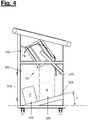
- FIGs 2 to 4 show the internal structure of the parcel box with the receiving device in different positions.
- figure 2 shows a loading position (S1).
- figure 3 shows a transitional position (S2).
- figure 4 shows the recording device in a tilted position (S3).
- the receiving device In the loading position (S1), the receiving device is ready to be loaded with a package.
- the loading position (S1) also forms the basic position of the receiving device.
- the receiving device (200) is preferably designed so that liquids or solid debris can flow or slide out of the receiving device (200).
- the receiving device (200) is preferably designed without undercuts.
- the shelf (205) is particularly open at the front edge. That is, no upwardly protruding projection is arranged on the front edge. This makes it particularly easy to wipe the storage surface. Leaves or other debris cannot accumulate in undercuts.
- the cross section of the feed chute (210) only increases towards the front or remains constant. In particular, the receiving device (200) does not narrow the cross section at the front.
- the storage surface (205) preferably has a slight incline towards the front.
- the loading position (S1) of the receiving device (200) is preferably designed in such a way that the receiving device is inclined to the horizontal.
- the shelf (205) is preferably inclined at a run-off angle (X) to a horizontal (H).
- the inclination preferably forms a gradient towards the front of the parcel box.
- the run-off angle (X) is approximately 5 degrees.
- the drainage angle In a further embodiment, (X) can also be 5-25 degrees, preferably 20 degrees.
- the slope is designed in such a way that liquids can flow out of the receiving device to the outside. This prevents liquids from entering the interior of the parcel box.
- the receiving device can be sealed, in particular on the back.
- a handle (220) is advantageously arranged at the lower end of the sloping shelf (205). In this way, the operator can insert the package and, despite the run-off angle (X), secure the package from slipping out until the receiving device is pivoted backwards with the handle (220).
- figure 3 shows the parcel box in a transitional position (S2) of the receiving device (200).
- the transition position (S2) lies along the movement from a loading position (S1) towards the tilting position (S3).
- the receiving device (200) In the transitional position (S2), the receiving device (200) inclines into the interior of the parcel box. The inclination increases along the pan movement. When a sliding angle is exceeded, the package (P) lying in the receiving device begins to slide. The package (P) slides toward the back of the pickup.
- the parcel box preferably includes a release device (230).
- the Release device (23) designed as a flap.
- the flap is preferably arranged on the back of the receiving device (200).
- the package (P) is held in a temporary position at the rear of the receptacle by the release device (230).
- the release device (230) is preferably designed in such a way that it is not possible to penetrate into the collection container from the outside. Access to the collection container (300) is only released once a sufficient pivoting angle has been reached.
- the release device (230) is preferably positively guided in its movement.
- the movement of the release device (230) is coupled to the pivoting movement of the receiving device (200).
- the parcel box preferably comprises guide means (240), in particular at least one guide rail.
- the guide means (240) are designed to guide the movement of the receiving device (200) and/or the release device (230).
- the guide rail (240) can in particular comprise a groove. A guide pin of the flap (230) can be guided in the groove.
- This advantageous design of the parcel box allows access to the collection container only in a transitional position (S2) and/or a tilted position (S3). Especially in the basic position, ie the loading position (S1), access to the collection container (300) is blocked by the receiving device (200).
- figure 4 shows the parcel box in a tilted position (S3).
- a package (P) is tipped out of the receiving device into the collection container (300).
- the release device (230) releases the path for a package (P) into the collection container (300).
- the package (P) advantageously slides into the collection container (300).
- the impact of the package (P) on the collection base (305) is cushioned by suitable means.
- the collection floor (305) can be suspended in particular in a spring-loaded and/or damped manner.
- the collection base (305) can be designed to be shock-absorbing.
- the package (P) falls into the collecting container (300) in a dropping area (320).
- the collecting container (300) preferably comprises a dropping area (320) and a collecting area (330).
- the collecting base (305) of the collecting container (300) has an incline.
- the collection floor (305) is preferably inclined by a sliding angle (Y) towards the removal access (310).
- the slip angle is preferably 10 degrees to 20 degrees, in particular 15 degrees.
- a package (P) landing in the drop area (320) can slide into the collection area (330) due to the incline of the collection floor (305).
- the collection base (305) is preferably designed with a smooth surface, in particular one that promotes sliding.
- the slope of the collection tray (305) is advantageous for an ergonomic removal of the packages (P) through the removal access (310).
- the dropping area (320) and the collecting area (330) are sufficiently spaced apart. In this way, several packages can be dropped side by side into the collection container. This increases the capacity of the collection container.
- the collection area (330) and the discharge area (320) preferably do not overlap.
- the collecting area (330) and the dropping area (320) preferably do not overlap.
- the collecting container (300) is preferably dimensioned at least twice as deep as a maximum dimension of the feed shaft (210).
- the receiving device (200) is preferably moved back into the basic position with a restoring force (FR).
- the restoring force (FR) can be brought about by applying a torque and/or a force.
- the receiving device is advantageously suspended in the parcel box in such a way that gravity causes a restoring force (FR).
- the pivot axis of the receiving device (200) is spaced from the center of gravity of the receiving device (200). In particular, the pivot axis is arranged further to the rear than the center of gravity of the receiving device (200). The pivoting movement of the receiving device (200) is advantageously damped.
- figure 5 shows a front view of a further advantageous embodiment of the parcel box.
- the parcel box can be designed in several variants. In particular, scaling the ierebox in several size levels is advantageous for different customer needs. Both the receiving device (200) and the collection container (300) can be made in different sizes. A design of the parcel box as a series is particularly advantageous.
- the parcel box preferably includes a frame (600).
- the frame construction includes several frame members (610).
- the frame elements (610) serve as support elements for the components of the parcel box.
- the frame elements are preferably designed as aluminum profiles, in particular with standardized dimensions. Such frame elements can be obtained inexpensively.
- the design as a frame construction with aluminum profiles enables the parcel box to be easily scaled up to several size levels.
- the parcel box has a modular design.
- the parcel box includes standard elements in several sizes, which can be put together as modules. This means that many variants can be built with just a few components.
- the storage surface (205) is preferably inclined at an angle (X) of 10 to 30 degrees, particularly advantageously at 20 degrees, relative to the horizontal. This allows rainwater to run off to the front even better.
- the collection container (300) remains dry even in severe weather.
- the parcel box includes both a lock (250) for the receiving device (200) and a lock (250) for the removal access (310). Both locks can preferably be locked with the same key.
- a lock for the removal access (310) is particularly advantageous, in which the key can only be removed in the locked position. This can prevent the removal access from accidentally remaining unlocked.
- the locking (250) of the removal access (310) preferably comprises a rotating bolt.
- the lock can preferably only be locked with a key. This prevents accidental locking of the key or children playing.
- the parcel box can also include feet (400).
- the feet (400) are preferably adjustable. This ensures a secure footing even on uneven ground.
- the feet (400) can include anchorages for attachment to the floor. In this way, the parcel box (e.g. with dowels) can be firmly connected to the subsurface.
- figure 6 shows a particularly advantageous embodiment of a release device (230) of the receiving device (200).
- the illustration shows a side view of the parcel box with the side panel hidden.
- the release device (230) advantageously comprises a flap.
- the flap (230) is preferably rotatably mounted on the upper edge of the rear of the receiving device (200).
- the release device preferably comprises a hinge for the flap.
- the flap can be positively guided along the pivoting movement of the receiving device (200) with guide means.
- the flap can be opened by its own weight and/or the weight of a package (P).
- the parcel box preferably includes a flap lock (242).
- the flap lock is designed to lock the release device (230) in the loading position (S1) of the receiving device (200).
- the release device (230) preferably cannot be actuated in the loading position (S1) of the receiving device (200). Unintentional opening of the release device in the loading position can thus be prevented, in particular when the receiving device is locked. In this way, the owner can protect himself against unintentionally loading or throwing rubbish into the parcel box while he is away.
- the flap lock (243) is preferably guided by a guide cable (243).
- the guide cable (243) is preferably attached to the upper, rear edge of the receiving device (200).
- the flap lock (243) is released by the guide cable (243) synchronously with the movement of the receiving device (200).
- the flap lock (242) can be pushed away by the receiving device only one pivoting movement in the direction of the tilted position (S3). After a predetermined pivoting path, the flap (230) is no longer blocked by the flap lock (242) and can open.
- the flap lock (242) preferably pivots downwards away.
- the flap lock (242) is preferably pivotably mounted on the parcel box, in particular on a frame (600).
- the flap lock is preferably mounted with a hinge on the upper rear edge of the parcel box (100).
- the flap lock comprises a widened contact surface at one end for contact with the flap to be locked.
- the parcel box can include a protective bracket (260) as additional protection against the ingress of moisture.
- the protective console is preferably arranged below the receiving device (200).
- the protective console is designed to protect the interior of the parcel box, in particular the collection container (300), against the ingress of environmental influences (e.g. rainwater) or access by people during the pivoting movement of the receiving device (200).
- the receiving device (200) pivots about a fixed axis.
- the parcel box includes a spring and/or damper, preferably a gas pressure spring with a damper, which is designed to exert a restoring force on the receiving device.
- the restoring means in particular the Gas pressure spring, the recording device is moved back to the basic position.
- the parcel box has a slip aid on the inside rear side, in particular in the form of vertical profiles.
- the sliding aid is designed to prevent a package (P) from tilting on a frame element on the back of the package box.
- Figures 7a - 7d show a loading process of a parcel box.
- the parcel (P) is placed in the receiving device (200) in the basic position (S1) from the front (V) of the parcel box.
- the recording device is then moved to the tilted position (S3).
- the flap lock (242) deviates from the receiving device (200) in the tilted position (S3) to the rear.
- the package (P) slides into the collection container (300) and lands on the inclined collection floor (305). Due to the inclination, the package (P) slides towards the front (V).
- the receiving device (200) pivots back into the basic position (S1) and is immediately ready for loading again.
- figure 8 shows a further embodiment of the guide means (240) for the receiving device (200).
- the guiding means (240) can in particular comprise one or more restoring means (270), in particular springs.
- the restoring means are preferably designed to return the receiving device (200) to the basic position (S1).
- the return means can alternatively or additionally also be designed to support the pivoting movement of the receiving device towards the tilted position (S3).
- a combination of several restoring means (270), which apply different forces to the receiving device (200) in different sections of the movement of the receiving device (200) between the basic position (S1) and the tilted position (S3), is particularly advantageous. These forces can at least partially act in opposite directions.
- the restoring means (270) can also include a damper.
- Gas pressure springs and/or tension springs, which are each suspended at suitable points between the pivoting receiving device (200) and the frame (600), are particularly advantageous.
- a comfortable and safe dynamic of the pivoting movement can be achieved by combining several restoring means (270).
- the user is supported in the actuation of the receiving device and the receiving device is always returned safely to the loading position after actuation.
- FIG 9 shows an embodiment of the parcel box for multiple users.
- the parcel box comprises a number of separate receiving devices (200) and/or a number of separate collection containers (300). Such an embodiment is particularly advantageous for apartment buildings or semi-detached houses.
- the parcel box can include more than two receiving devices (200) and/or collection containers (300).
- the multiple receiving devices and/or collection containers can in particular be arranged next to and/or below one another in a common parcel box.
- the parcel box preferably includes a common frame (600) and/or a common roof.
- the receiving device (200) and/or the collection container (300) can be designed in particular as modular slide-in units for a frame (600).
- the same modules can preferably be used in different numbers for different numbers of recipients.
- the parcel box is advantageously of purely mechanical design.
- the parcel box does not require any active electrical drives, such as motors. As a result, the requirements for the installation site are low.
- the parcel box does not require any electrical power supply and can therefore be operated independently of the installation site. Thanks to the advantageous construction, the user's energy can be used to operate the parcel box.
- the parcel box can also contain individual additional electrical components. These components are preferably battery operated. Alternatively, the parcel box can also include a charging connection or a mains connection.
- the parcel box can in particular include a sensor or an electronic display.
- the parcel box can too an electronic control unit, in particular with a communication module.
- the parcel box is designed to detect a parcel being dropped with a sensor and to send a signal via a communication interface.
- the parcel box can include a remote-controllable lock.
- the disclosure includes in particular: A parcel box, wherein the receiving device (200) comprises a feed chute (210), which in particular forms at least the storage area (205).
- the storage area of the receiving device is preferably flat. The cross-section of the feed chute only increases towards the front or remains the same. The storage surface is free of projections that reach into the feed chute.
- a parcel box, the receiving device (200) being designed to allow rubbish and/or liquids to flow off and/or slide off the storage surface (205) towards the front.
- a parcel box wherein the storage area (205) has a smooth surface, which in particular produces low static friction.
- a parcel box wherein the collection container (300) comprises a collection floor (305) sloping down to a removal access (310).
- a parcel box the collection container having a drop-off area (320) and a collection area (330).
- a parcel box, the collection container (300) being designed in such a way that parcels (P) slide from a drop-off area (320) into a collection area (330).
- a mobile parcel box A parcel box with castors, in particular brakeable and/or lockable castors.
- a parcel box that is designed to be attached to a building, in particular to a house wall, or to be built into a building.
- REFERENCE LIST 100 parcel box Parcel containers 200 recording device receiving device 201 wall panel 205 storage space Deposition surface 210 feed chute feeding duct 220 Handle handle 230 Release device, flap Release device, flap 235 flap lock flap lock 240 Guide means, guide rail Guiding means, guiding rail 241 pivot axis pivot axis 242 flap lock flap guide 243 guide rope guiding rope 250 locking lock 260 protection console protection panel 270 return means Reset means 300 collection container Storage container 305 collecting floor storage base 310 withdrawal access, door Pickup access, door 320 drop area Drop area 330 collection area Storage area 400 rolls, feet Rollers, feet 500 cover, roof Cover, roof 600 frame frames 610 frame elements Frame components S1 Loading position, basic position Loading position, rest position S2 transitional position Transitional position S3 tilt position dumping position P package, shipping package parcel FR restoring force Reset force V Front, loading side Front side, loading side H horizontal Horizontal X drainage angle drain angle Y slide angle Slide angle
Landscapes
- Engineering & Computer Science (AREA)
- Food Science & Technology (AREA)
- Supports Or Holders For Household Use (AREA)
Claims (15)
- Boîte à colis pour la réception et le stockage de colis (P), comprenant un dispositif de réception pivotant (200) et un contenant de collecte (300), le dispositif de réception (200) comprenant une surface de dépôt (205) et étant configuré pour être chargé avec un colis (P) dans une position de chargement (S1), et le dispositif de réception (200) pouvant pivoter dans une position de basculement (S3), dans laquelle un colis (P) peut être basculé hors du dispositif de réception (200) dans le contenant de collecte (300), caractérisée en ce que la boîte à colis (100) comprend un moyen de repositionnement (270), la position de chargement (S1) formant la position de base sans actionnement du dispositif de réception (200) et le dispositif de réception (200) étant configuré pour se repositionner automatiquement dans la position de chargement (S1) par application d'une force de repositionnement.
- Boîte à colis selon la revendication 1, dans laquelle la boîte à colis (100) est configurée de telle sorte que le dispositif de réception (200), notamment la surface de dépôt (205), est librement accessible dans la position de base.
- Boîte à colis selon l'une quelconque des revendications 1 ou 2, dans laquelle le dispositif de réception (200) est configuré pour rester automatiquement dans la position de chargement (S1).
- Boîte à colis selon l'une quelconque des revendications précédentes, dans laquelle la surface de dépôt (205), notamment dans la position de base, est configurée de manière à être en pente vers le côté avant (V), notamment est inclinée d'un angle d'évacuation (X) par rapport à une horizontale (H).
- Boîte à colis selon l'une quelconque des revendications précédentes, dans laquelle le dispositif de réception (200) comprend un dispositif de libération (230), notamment un clapet, qui est configuré pour libérer un colis (P) à partir du dispositif de réception (200) dans le contenant de collecte (300).
- Boîte à colis selon la revendication 5, dans laquelle le dispositif de libération (230) est agencé sur le côté arrière du dispositif de réception (200), notamment sur le côté arrière du puits d'alimentation (210) .
- Boîte à colis selon la revendication 5 ou 6, dans laquelle le dispositif de libération (230) est configuré pour libérer un colis (P) en fonction de l'angle de pivotement du dispositif de réception (200).
- Boîte à colis selon l'une quelconque des revendications précédentes, dans laquelle la boîte à colis (100) comprend un dispositif de libération (230) couplé cinématiquement au mouvement de pivotement du dispositif de réception (200).
- Boîte à colis selon l'une quelconque des revendications précédentes, dans laquelle la boîte à colis (100) comprend des moyens de guidage (240), notamment au moins un rail de guidage et/ou un axe, qui sont configurés pour guider le mouvement du dispositif de réception (200) et/ou d'un dispositif de libération (230) .
- Boîte à colis selon l'une quelconque des revendications précédentes, dans laquelle le contenant de collecte (300) comprend un accès de prélèvement (310), notamment une porte.
- Boîte à colis selon l'une quelconque des revendications précédentes, dans laquelle le contenant de collecte (300) présente un fond de collecte (305) incliné d'un angle de glissement (Y) par rapport à une horizontale (H).
- Boîte à colis selon l'une quelconque des revendications précédentes, dans laquelle le dispositif de réception (200) comprend une poignée (220) sur laquelle le dispositif de réception (200) peut pivoter manuellement.
- Boîte à colis selon l'une quelconque des revendications précédentes, dans laquelle la boîte à colis (100) comprend un ressort mécanique ou pneumatique, qui est configuré pour ramener le dispositif de réception (200) dans la position de base avec une force de repositionnement (FR).
- Boîte à colis selon la revendication 13, dans laquelle le moyen de repositionnement (270) est configuré pour assister le mouvement du dispositif de réception (S1) d'une position de basculement (S3) ou d'une position de transition (S2) vers une position de chargement (S1) et/ou pour provoquer celui-ci de manière autonome.
- Boîte à colis selon l'une quelconque des revendications précédentes, dans laquelle le dispositif de réception (200) peut être verrouillé avec un verrou (250), notamment pouvant être bloqué.
Applications Claiming Priority (1)
| Application Number | Priority Date | Filing Date | Title |
|---|---|---|---|
| DE202018106563.7U DE202018106563U1 (de) | 2018-11-20 | 2018-11-20 | Paketbox |
Publications (2)
| Publication Number | Publication Date |
|---|---|
| EP3656258A1 EP3656258A1 (fr) | 2020-05-27 |
| EP3656258B1 true EP3656258B1 (fr) | 2022-07-20 |
Family
ID=65235032
Family Applications (1)
| Application Number | Title | Priority Date | Filing Date |
|---|---|---|---|
| EP19205833.7A Active EP3656258B1 (fr) | 2018-11-20 | 2019-10-29 | Boîte pour colis |
Country Status (2)
| Country | Link |
|---|---|
| EP (1) | EP3656258B1 (fr) |
| DE (1) | DE202018106563U1 (fr) |
Families Citing this family (2)
| Publication number | Priority date | Publication date | Assignee | Title |
|---|---|---|---|---|
| DE202021102570U1 (de) | 2021-05-11 | 2021-06-23 | Manfred HÖLSCHER | Paketbox |
| DE202022000133U1 (de) | 2022-01-19 | 2022-02-22 | Marvin Pechmann | Elektromechanische Paketstation für den Empfang von Zustellsendungen und Versand von Abholsendungen bei Abwesenheit |
Family Cites Families (5)
| Publication number | Priority date | Publication date | Assignee | Title |
|---|---|---|---|---|
| DE29619083U1 (de) * | 1996-11-04 | 1998-03-05 | JO-BA Maschinen- und Anlagenbau GmbH, 27211 Bassum | Sammelbehälter |
| DE1252845T1 (de) * | 2001-10-02 | 2003-06-26 | Sportaccess S.A., Sion | Empfangsmodul zur kontaklosen Annahme von Gegenständen, die mit einem Daten enthaltenden Chip versehen sind |
| US7428980B2 (en) * | 2004-07-30 | 2008-09-30 | United States Postal Service | Parcel collection device |
| DE102006039002B4 (de) * | 2006-08-21 | 2011-06-01 | Deutsche Post Ag | Sammelbehälter, insbesondere zur Sammlung von Paketen |
| DE102015119885A1 (de) * | 2015-11-17 | 2017-05-18 | Paul Schmitz | Beschickungsvorrichtung für einen Sammelbehälter |
-
2018
- 2018-11-20 DE DE202018106563.7U patent/DE202018106563U1/de not_active Expired - Lifetime
-
2019
- 2019-10-29 EP EP19205833.7A patent/EP3656258B1/fr active Active
Also Published As
| Publication number | Publication date |
|---|---|
| DE202018106563U1 (de) | 2019-01-14 |
| EP3656258A1 (fr) | 2020-05-27 |
Similar Documents
| Publication | Publication Date | Title |
|---|---|---|
| DE102006039002B4 (de) | Sammelbehälter, insbesondere zur Sammlung von Paketen | |
| DE202014011277U1 (de) | Modulares Paket-Terminal zum Senden von Paketen | |
| US10190310B2 (en) | Waterproof storage unit | |
| AT519275B1 (de) | Aufzug sowie Verfahren zur Lieferung von Paketen | |
| EP3656258A1 (fr) | Boîte pour colis | |
| EP1358117B1 (fr) | Dispositif de stockage et de transfert de marchandises dans des paquets de petite taille | |
| DE19837453A1 (de) | Bodenversenkbares Gehäuse mit hydraulischer Hebevorrichtung | |
| DE102014209510B3 (de) | Klappbox | |
| JPH06500299A (ja) | 飛行機用ごみ圧縮装置 | |
| WO2017005991A1 (fr) | Rangement ergonomique | |
| DE202021003314U1 (de) | Tragvorrichtung | |
| DE102016205992A1 (de) | Kältegerät mit Flaschenhalter | |
| DE84206C (fr) | ||
| EP2242404A2 (fr) | Contenant de protection | |
| DE202021102570U1 (de) | Paketbox | |
| DE102010053673B4 (de) | Übergabestation mit Diebstahlschutz | |
| WO2024200727A1 (fr) | Unité de stockage | |
| DE29814629U1 (de) | Bodenversenkbares Gehäuse mit hydraulischer Hebevorrichtung | |
| EP2289376A1 (fr) | Boîte à lettres et système de boîte à lettres | |
| DE2244189A1 (de) | Vorrichtung zur muellbeseitigung in bauten mit hilfe von abwurfschaechten | |
| DE202023107647U1 (de) | Vorrichtung zur Aufnahme / Annahme und temporären Aufbewahrung von Brief- und Paketsendungen | |
| DE102023126644A1 (de) | Ausgabevorrichtung zur Ausgabe von flachen Artikeln | |
| DE4200387A1 (de) | Muellbehaelter-system | |
| DE8318878U1 (de) | Abfallbehaelter fuer aussenanlagen | |
| DE102021101662A1 (de) | Notvorräte enthaltendes mehrzweckschranksystem |
Legal Events
| Date | Code | Title | Description |
|---|---|---|---|
| PUAI | Public reference made under article 153(3) epc to a published international application that has entered the european phase |
Free format text: ORIGINAL CODE: 0009012 |
|
| STAA | Information on the status of an ep patent application or granted ep patent |
Free format text: STATUS: THE APPLICATION HAS BEEN PUBLISHED |
|
| AK | Designated contracting states |
Kind code of ref document: A1 Designated state(s): AL AT BE BG CH CY CZ DE DK EE ES FI FR GB GR HR HU IE IS IT LI LT LU LV MC MK MT NL NO PL PT RO RS SE SI SK SM TR |
|
| AX | Request for extension of the european patent |
Extension state: BA ME |
|
| STAA | Information on the status of an ep patent application or granted ep patent |
Free format text: STATUS: REQUEST FOR EXAMINATION WAS MADE |
|
| 17P | Request for examination filed |
Effective date: 20200617 |
|
| RBV | Designated contracting states (corrected) |
Designated state(s): AL AT BE BG CH CY CZ DE DK EE ES FI FR GB GR HR HU IE IS IT LI LT LU LV MC MK MT NL NO PL PT RO RS SE SI SK SM TR |
|
| GRAP | Despatch of communication of intention to grant a patent |
Free format text: ORIGINAL CODE: EPIDOSNIGR1 |
|
| STAA | Information on the status of an ep patent application or granted ep patent |
Free format text: STATUS: GRANT OF PATENT IS INTENDED |
|
| INTG | Intention to grant announced |
Effective date: 20220216 |
|
| GRAS | Grant fee paid |
Free format text: ORIGINAL CODE: EPIDOSNIGR3 |
|
| GRAA | (expected) grant |
Free format text: ORIGINAL CODE: 0009210 |
|
| STAA | Information on the status of an ep patent application or granted ep patent |
Free format text: STATUS: THE PATENT HAS BEEN GRANTED |
|
| AK | Designated contracting states |
Kind code of ref document: B1 Designated state(s): AL AT BE BG CH CY CZ DE DK EE ES FI FR GB GR HR HU IE IS IT LI LT LU LV MC MK MT NL NO PL PT RO RS SE SI SK SM TR |
|
| REG | Reference to a national code |
Ref country code: CH Ref legal event code: EP |
|
| REG | Reference to a national code |
Ref country code: DE Ref legal event code: R096 Ref document number: 502019005006 Country of ref document: DE |
|
| REG | Reference to a national code |
Ref country code: AT Ref legal event code: REF Ref document number: 1504996 Country of ref document: AT Kind code of ref document: T Effective date: 20220815 |
|
| REG | Reference to a national code |
Ref country code: IE Ref legal event code: FG4D Free format text: LANGUAGE OF EP DOCUMENT: GERMAN |
|
| REG | Reference to a national code |
Ref country code: LT Ref legal event code: MG9D |
|
| REG | Reference to a national code |
Ref country code: NL Ref legal event code: MP Effective date: 20220720 |
|
| PG25 | Lapsed in a contracting state [announced via postgrant information from national office to epo] |
Ref country code: SE Free format text: LAPSE BECAUSE OF FAILURE TO SUBMIT A TRANSLATION OF THE DESCRIPTION OR TO PAY THE FEE WITHIN THE PRESCRIBED TIME-LIMIT Effective date: 20220720 Ref country code: RS Free format text: LAPSE BECAUSE OF FAILURE TO SUBMIT A TRANSLATION OF THE DESCRIPTION OR TO PAY THE FEE WITHIN THE PRESCRIBED TIME-LIMIT Effective date: 20220720 Ref country code: PT Free format text: LAPSE BECAUSE OF FAILURE TO SUBMIT A TRANSLATION OF THE DESCRIPTION OR TO PAY THE FEE WITHIN THE PRESCRIBED TIME-LIMIT Effective date: 20221121 Ref country code: NO Free format text: LAPSE BECAUSE OF FAILURE TO SUBMIT A TRANSLATION OF THE DESCRIPTION OR TO PAY THE FEE WITHIN THE PRESCRIBED TIME-LIMIT Effective date: 20221020 Ref country code: NL Free format text: LAPSE BECAUSE OF FAILURE TO SUBMIT A TRANSLATION OF THE DESCRIPTION OR TO PAY THE FEE WITHIN THE PRESCRIBED TIME-LIMIT Effective date: 20220720 Ref country code: LV Free format text: LAPSE BECAUSE OF FAILURE TO SUBMIT A TRANSLATION OF THE DESCRIPTION OR TO PAY THE FEE WITHIN THE PRESCRIBED TIME-LIMIT Effective date: 20220720 Ref country code: LT Free format text: LAPSE BECAUSE OF FAILURE TO SUBMIT A TRANSLATION OF THE DESCRIPTION OR TO PAY THE FEE WITHIN THE PRESCRIBED TIME-LIMIT Effective date: 20220720 Ref country code: FI Free format text: LAPSE BECAUSE OF FAILURE TO SUBMIT A TRANSLATION OF THE DESCRIPTION OR TO PAY THE FEE WITHIN THE PRESCRIBED TIME-LIMIT Effective date: 20220720 Ref country code: ES Free format text: LAPSE BECAUSE OF FAILURE TO SUBMIT A TRANSLATION OF THE DESCRIPTION OR TO PAY THE FEE WITHIN THE PRESCRIBED TIME-LIMIT Effective date: 20220720 |
|
| PG25 | Lapsed in a contracting state [announced via postgrant information from national office to epo] |
Ref country code: PL Free format text: LAPSE BECAUSE OF FAILURE TO SUBMIT A TRANSLATION OF THE DESCRIPTION OR TO PAY THE FEE WITHIN THE PRESCRIBED TIME-LIMIT Effective date: 20220720 Ref country code: IS Free format text: LAPSE BECAUSE OF FAILURE TO SUBMIT A TRANSLATION OF THE DESCRIPTION OR TO PAY THE FEE WITHIN THE PRESCRIBED TIME-LIMIT Effective date: 20221120 Ref country code: HR Free format text: LAPSE BECAUSE OF FAILURE TO SUBMIT A TRANSLATION OF THE DESCRIPTION OR TO PAY THE FEE WITHIN THE PRESCRIBED TIME-LIMIT Effective date: 20220720 Ref country code: GR Free format text: LAPSE BECAUSE OF FAILURE TO SUBMIT A TRANSLATION OF THE DESCRIPTION OR TO PAY THE FEE WITHIN THE PRESCRIBED TIME-LIMIT Effective date: 20221021 |
|
| REG | Reference to a national code |
Ref country code: DE Ref legal event code: R097 Ref document number: 502019005006 Country of ref document: DE |
|
| PG25 | Lapsed in a contracting state [announced via postgrant information from national office to epo] |
Ref country code: SM Free format text: LAPSE BECAUSE OF FAILURE TO SUBMIT A TRANSLATION OF THE DESCRIPTION OR TO PAY THE FEE WITHIN THE PRESCRIBED TIME-LIMIT Effective date: 20220720 Ref country code: RO Free format text: LAPSE BECAUSE OF FAILURE TO SUBMIT A TRANSLATION OF THE DESCRIPTION OR TO PAY THE FEE WITHIN THE PRESCRIBED TIME-LIMIT Effective date: 20220720 Ref country code: DK Free format text: LAPSE BECAUSE OF FAILURE TO SUBMIT A TRANSLATION OF THE DESCRIPTION OR TO PAY THE FEE WITHIN THE PRESCRIBED TIME-LIMIT Effective date: 20220720 Ref country code: CZ Free format text: LAPSE BECAUSE OF FAILURE TO SUBMIT A TRANSLATION OF THE DESCRIPTION OR TO PAY THE FEE WITHIN THE PRESCRIBED TIME-LIMIT Effective date: 20220720 |
|
| PLBE | No opposition filed within time limit |
Free format text: ORIGINAL CODE: 0009261 |
|
| STAA | Information on the status of an ep patent application or granted ep patent |
Free format text: STATUS: NO OPPOSITION FILED WITHIN TIME LIMIT |
|
| PG25 | Lapsed in a contracting state [announced via postgrant information from national office to epo] |
Ref country code: SK Free format text: LAPSE BECAUSE OF FAILURE TO SUBMIT A TRANSLATION OF THE DESCRIPTION OR TO PAY THE FEE WITHIN THE PRESCRIBED TIME-LIMIT Effective date: 20220720 Ref country code: MC Free format text: LAPSE BECAUSE OF FAILURE TO SUBMIT A TRANSLATION OF THE DESCRIPTION OR TO PAY THE FEE WITHIN THE PRESCRIBED TIME-LIMIT Effective date: 20220720 Ref country code: EE Free format text: LAPSE BECAUSE OF FAILURE TO SUBMIT A TRANSLATION OF THE DESCRIPTION OR TO PAY THE FEE WITHIN THE PRESCRIBED TIME-LIMIT Effective date: 20220720 |
|
| REG | Reference to a national code |
Ref country code: CH Ref legal event code: PL |
|
| REG | Reference to a national code |
Ref country code: BE Ref legal event code: MM Effective date: 20221031 |
|
| 26N | No opposition filed |
Effective date: 20230421 |
|
| PG25 | Lapsed in a contracting state [announced via postgrant information from national office to epo] |
Ref country code: LU Free format text: LAPSE BECAUSE OF NON-PAYMENT OF DUE FEES Effective date: 20221029 Ref country code: AL Free format text: LAPSE BECAUSE OF FAILURE TO SUBMIT A TRANSLATION OF THE DESCRIPTION OR TO PAY THE FEE WITHIN THE PRESCRIBED TIME-LIMIT Effective date: 20220720 |
|
| PG25 | Lapsed in a contracting state [announced via postgrant information from national office to epo] |
Ref country code: LI Free format text: LAPSE BECAUSE OF NON-PAYMENT OF DUE FEES Effective date: 20221031 Ref country code: FR Free format text: LAPSE BECAUSE OF NON-PAYMENT OF DUE FEES Effective date: 20221031 Ref country code: CH Free format text: LAPSE BECAUSE OF NON-PAYMENT OF DUE FEES Effective date: 20221031 |
|
| PG25 | Lapsed in a contracting state [announced via postgrant information from national office to epo] |
Ref country code: SI Free format text: LAPSE BECAUSE OF FAILURE TO SUBMIT A TRANSLATION OF THE DESCRIPTION OR TO PAY THE FEE WITHIN THE PRESCRIBED TIME-LIMIT Effective date: 20220720 |
|
| PG25 | Lapsed in a contracting state [announced via postgrant information from national office to epo] |
Ref country code: BE Free format text: LAPSE BECAUSE OF NON-PAYMENT OF DUE FEES Effective date: 20221031 |
|
| PG25 | Lapsed in a contracting state [announced via postgrant information from national office to epo] |
Ref country code: IE Free format text: LAPSE BECAUSE OF NON-PAYMENT OF DUE FEES Effective date: 20221029 |
|
| PG25 | Lapsed in a contracting state [announced via postgrant information from national office to epo] |
Ref country code: HU Free format text: LAPSE BECAUSE OF FAILURE TO SUBMIT A TRANSLATION OF THE DESCRIPTION OR TO PAY THE FEE WITHIN THE PRESCRIBED TIME-LIMIT; INVALID AB INITIO Effective date: 20191029 |
|
| PG25 | Lapsed in a contracting state [announced via postgrant information from national office to epo] |
Ref country code: CY Free format text: LAPSE BECAUSE OF FAILURE TO SUBMIT A TRANSLATION OF THE DESCRIPTION OR TO PAY THE FEE WITHIN THE PRESCRIBED TIME-LIMIT Effective date: 20220720 |
|
| PG25 | Lapsed in a contracting state [announced via postgrant information from national office to epo] |
Ref country code: MK Free format text: LAPSE BECAUSE OF FAILURE TO SUBMIT A TRANSLATION OF THE DESCRIPTION OR TO PAY THE FEE WITHIN THE PRESCRIBED TIME-LIMIT Effective date: 20220720 Ref country code: IT Free format text: LAPSE BECAUSE OF FAILURE TO SUBMIT A TRANSLATION OF THE DESCRIPTION OR TO PAY THE FEE WITHIN THE PRESCRIBED TIME-LIMIT Effective date: 20220720 |
|
| GBPC | Gb: european patent ceased through non-payment of renewal fee |
Effective date: 20231029 |
|
| PG25 | Lapsed in a contracting state [announced via postgrant information from national office to epo] |
Ref country code: TR Free format text: LAPSE BECAUSE OF FAILURE TO SUBMIT A TRANSLATION OF THE DESCRIPTION OR TO PAY THE FEE WITHIN THE PRESCRIBED TIME-LIMIT Effective date: 20220720 |
|
| PG25 | Lapsed in a contracting state [announced via postgrant information from national office to epo] |
Ref country code: GB Free format text: LAPSE BECAUSE OF NON-PAYMENT OF DUE FEES Effective date: 20231029 |
|
| PG25 | Lapsed in a contracting state [announced via postgrant information from national office to epo] |
Ref country code: GB Free format text: LAPSE BECAUSE OF NON-PAYMENT OF DUE FEES Effective date: 20231029 Ref country code: BG Free format text: LAPSE BECAUSE OF FAILURE TO SUBMIT A TRANSLATION OF THE DESCRIPTION OR TO PAY THE FEE WITHIN THE PRESCRIBED TIME-LIMIT Effective date: 20220720 |
|
| PG25 | Lapsed in a contracting state [announced via postgrant information from national office to epo] |
Ref country code: MT Free format text: LAPSE BECAUSE OF FAILURE TO SUBMIT A TRANSLATION OF THE DESCRIPTION OR TO PAY THE FEE WITHIN THE PRESCRIBED TIME-LIMIT Effective date: 20220720 |
|
| PGFP | Annual fee paid to national office [announced via postgrant information from national office to epo] |
Ref country code: DE Payment date: 20241022 Year of fee payment: 6 |
|
| REG | Reference to a national code |
Ref country code: AT Ref legal event code: MM01 Ref document number: 1504996 Country of ref document: AT Kind code of ref document: T Effective date: 20241029 |
|
| PG25 | Lapsed in a contracting state [announced via postgrant information from national office to epo] |
Ref country code: AT Free format text: LAPSE BECAUSE OF NON-PAYMENT OF DUE FEES Effective date: 20241029 |
|
| PGFP | Annual fee paid to national office [announced via postgrant information from national office to epo] |
Ref country code: AT Payment date: 20260410 Year of fee payment: 5 |