EP3656341A1 - Dispositif d'application et procédé de fabrication d'un dispositif d'application - Google Patents
Dispositif d'application et procédé de fabrication d'un dispositif d'application Download PDFInfo
- Publication number
- EP3656341A1 EP3656341A1 EP18208096.0A EP18208096A EP3656341A1 EP 3656341 A1 EP3656341 A1 EP 3656341A1 EP 18208096 A EP18208096 A EP 18208096A EP 3656341 A1 EP3656341 A1 EP 3656341A1
- Authority
- EP
- European Patent Office
- Prior art keywords
- application
- housing
- channel
- connection
- inlet port
- Prior art date
- Legal status (The legal status is an assumption and is not a legal conclusion. Google has not performed a legal analysis and makes no representation as to the accuracy of the status listed.)
- Withdrawn
Links
- 238000004519 manufacturing process Methods 0.000 title claims abstract description 19
- 150000001875 compounds Chemical class 0.000 claims abstract description 9
- 239000000463 material Substances 0.000 claims description 36
- 238000007599 discharging Methods 0.000 claims description 34
- 239000012530 fluid Substances 0.000 claims description 26
- 238000001746 injection moulding Methods 0.000 claims description 19
- 238000007789 sealing Methods 0.000 claims description 15
- 239000004033 plastic Substances 0.000 claims description 8
- 238000000465 moulding Methods 0.000 claims description 6
- 238000004026 adhesive bonding Methods 0.000 claims description 4
- 238000003466 welding Methods 0.000 claims description 4
- 238000000034 method Methods 0.000 description 7
- 238000011109 contamination Methods 0.000 description 6
- 229920002725 thermoplastic elastomer Polymers 0.000 description 5
- 239000007779 soft material Substances 0.000 description 4
- 239000007788 liquid Substances 0.000 description 3
- 238000009826 distribution Methods 0.000 description 2
- 230000001419 dependent effect Effects 0.000 description 1
- 239000007789 gas Substances 0.000 description 1
- 239000003562 lightweight material Substances 0.000 description 1
- 238000002360 preparation method Methods 0.000 description 1
- 238000013341 scale-up Methods 0.000 description 1
- 239000007787 solid Substances 0.000 description 1
Images




Classifications
-
- A—HUMAN NECESSITIES
- A61—MEDICAL OR VETERINARY SCIENCE; HYGIENE
- A61C—DENTISTRY; APPARATUS OR METHODS FOR ORAL OR DENTAL HYGIENE
- A61C5/00—Filling or capping teeth
- A61C5/60—Devices specially adapted for pressing or mixing capping or filling materials, e.g. amalgam presses
- A61C5/62—Applicators, e.g. syringes or guns
-
- A—HUMAN NECESSITIES
- A61—MEDICAL OR VETERINARY SCIENCE; HYGIENE
- A61C—DENTISTRY; APPARATUS OR METHODS FOR ORAL OR DENTAL HYGIENE
- A61C19/00—Dental auxiliary appliances
- A61C19/06—Implements for therapeutic treatment
- A61C19/063—Medicament applicators for teeth or gums, e.g. treatment with fluorides
-
- B—PERFORMING OPERATIONS; TRANSPORTING
- B29—WORKING OF PLASTICS; WORKING OF SUBSTANCES IN A PLASTIC STATE IN GENERAL
- B29C—SHAPING OR JOINING OF PLASTICS; SHAPING OF MATERIAL IN A PLASTIC STATE, NOT OTHERWISE PROVIDED FOR; AFTER-TREATMENT OF THE SHAPED PRODUCTS, e.g. REPAIRING
- B29C45/00—Injection moulding, i.e. forcing the required volume of moulding material through a nozzle into a closed mould; Apparatus therefor
- B29C45/0003—Injection moulding, i.e. forcing the required volume of moulding material through a nozzle into a closed mould; Apparatus therefor of successively moulded portions rigidly joined to each other
-
- B—PERFORMING OPERATIONS; TRANSPORTING
- B29—WORKING OF PLASTICS; WORKING OF SUBSTANCES IN A PLASTIC STATE IN GENERAL
- B29C—SHAPING OR JOINING OF PLASTICS; SHAPING OF MATERIAL IN A PLASTIC STATE, NOT OTHERWISE PROVIDED FOR; AFTER-TREATMENT OF THE SHAPED PRODUCTS, e.g. REPAIRING
- B29C45/00—Injection moulding, i.e. forcing the required volume of moulding material through a nozzle into a closed mould; Apparatus therefor
- B29C45/17—Component parts, details or accessories; Auxiliary operations
- B29C45/18—Feeding the material into the injection moulding apparatus, i.e. feeding the non-plastified material into the injection unit
- B29C45/1866—Feeding multiple materials
-
- A—HUMAN NECESSITIES
- A61—MEDICAL OR VETERINARY SCIENCE; HYGIENE
- A61C—DENTISTRY; APPARATUS OR METHODS FOR ORAL OR DENTAL HYGIENE
- A61C2201/00—Material properties
-
- B—PERFORMING OPERATIONS; TRANSPORTING
- B29—WORKING OF PLASTICS; WORKING OF SUBSTANCES IN A PLASTIC STATE IN GENERAL
- B29L—INDEXING SCHEME ASSOCIATED WITH SUBCLASS B29C, RELATING TO PARTICULAR ARTICLES
- B29L2031/00—Other particular articles
- B29L2031/753—Medical equipment; Accessories therefor
- B29L2031/7544—Injection needles, syringes
Definitions
- the present invention relates to an application device, in particular for dental compounds, comprising a housing and an application tool. Further, the present invention relates to a method for producing an application device.
- Application devices for the application of fluids are commonly used. Such application devices can be used with liquid fluids and gaseous fluids. Application devices often are connected to discharging devices, providing different ways of application, for instance in terms of application area and/or distribution. Especially for an application of dental compounds it is known to use such application devices.
- application devices are changed often, especially after each single usage or at least before the treatment of the next patient. This results in a high consumption of application devices.
- an object of the present invention to provide an improved application device and an improved method for producing such an application device.
- an application device in particular for dental compounds, comprising a housing and an application tool, the housing comprising an application channel extending through the housing and having an application channel inlet port and an application outlet, the application channel outlet being in fluid connection with the application tool;
- the application device further comprising a connection section being distinct from the housing, the connection section comprising a connection channel having a connection channel inlet port and a connection channel outlet port; further the connection section comprising connection means arranged at the connection channel inlet port, the connecting means being configured to be connected to an outlet port of a discharging device, in particular by inserting the connecting means into the outlet port of the discharging device;
- the connection channel outlet port being configured to be sealingly connected to the application channel inlet port to build a discharging channel extending from the connection channel inlet port to the application channel outlet;
- the housing further comprising a shielding section, the shielding section is standing apart from the connection section and surrounding the connection section when the connection channel outlet port is connected to the application channel inlet port;
- An application device according to the invention can be used for an application of fluids, for instance liquids or gases. Especially and in particular an application device according to the invention can be used to applicate dental compounds, for instance on the tooth of a patient. As such application devices often are changed after a single usage or at least as preparation for the next patient, a large number of such application devices are needed. This can easily be provided with an application device according to the invention, as the production of such an application device according to the invention is simplified and especially the production cost is lowered.
- an application device essentially comprises two parts, a housing including an application tool and distinct from this component a connection section.
- the housing comprises an application channel, which extends through the housing.
- the application channel has on its first end an application channel inlet port and on its second end an application channel outlet port. Therefore, fluid can be transported through the housing via this application channel.
- the application channel outlet is in fluid connection with the application tool, wherein the application tool is used to applicate the fluid onto the target surface.
- connection section on the other hand is distinct from the housing. It comprises a connection channel which extends through the connection section.
- the connection channel comprises a connection channel inlet port on its first end and the connection channel outlet port on its second end.
- connection channel outlet port is constructed such that it can be sealingly connected to the application channel inlet port.
- connection channel and the application channel run obliquely to each other when the connection channel outlet port is connected to the application channel inlet port.
- Obliquely in the scope of the present invention especially means an angle between the connection channel and the application channel of 5° to 85°, essentially of 20° to 55°, preferably of 30°.
- the connection channel and the application channel are arranged in a kinked configuration. Therefore, target areas not reachable for application devices with a completely straight channel can be reached. Especially for dental compounds this means that all areas within the mouth of a patent can be reached easily.
- connection section comprising connecting means arranged at the connection channel inlet port to connect the application device to an outlet port of a discharging device.
- this can be provided by inserting the connection means into the outlet port of the discharging device.
- a connection between the application device and the discharging device, wherein the discharging device provides the fluid to be applicated, can therefore be provided in an easy way.
- the housing comprises a shielding section.
- This shielding section stands apart from the connection section and surrounds the connection section when the channel outlet port is connected to the application channel inlet port.
- the shielding section forms an inner volume of the housing.
- the shielding section is an element of an application device according to the invention distinct of the connection section and especially never physically touching the connection section although surrounding it. Therefore the connection section is shielded by the shielding section from direct contact, especially manual direct contact.
- the shielding section extends beyond the connection channel inlet port in the direction of the connection section.
- the direction of the connection section can be preferably also the direction of the connection channel and is a general direction, which extends linear along the connection section and/or the connection channel.
- connection channel inlet port and the connection section as a whole are recessed and therefore protected. A manual contact especially of the discharging channel and the risk of a contamination can therefore be lowered.
- connection channel and/or the application channel are linearly extending channels.
- Linear extending channels can be produced especially easily, in particular if an injection molding process is used to produce the housing sections.
- the production of an application device according to the invention can therefore be provided faster and at lower cost. Nevertheless, as the connection channel and the application channel run obliquely to each other, all advantages described above in respect of the kinked configuration of the resulting discharging channel can still be provided.
- an application device can be characterized in that the housing and/or the application tool and/or the connection section are made of plastic.
- Plastic is an especially light-weight material and additionally easy in its handling.
- different sorts of plastic are suitable and available and therefore a range of fluids to be applicated with an application device according to the invention can be extended.
- the production of an application device wherein the material used to produce the housing and/or the application tool and/or the connection section is plastic can be provided more easily, especially if an injection molding process is used to produce the housing sections and/or the application tool and/or the connection section.
- an application device can be characterized in that the material of the application tool is softer than the material of the housing and/or the material of the connection section.
- the application tool is used to applicate the fluid of the target surface. This procedure often includes a direct physical contact of the application tool and the target surface.
- a soft material especially a plastic material
- a soft material may be a material having a hardness measured with the Shore A Durometer selected in the range of 20A to 95A and up to a hardness measured with the Shore D Durometer of 55D.
- Typical examples of soft materials, especially plastic materials are TPEs (thermoplastic elastomers or thermoplastic rubbers). TPEs typically have a hardness measured on the "A” scale from 20 Shore “A” to 95 Shore “A”, with some harder TPE materials, i.e. materials harder than 90 Shore “A” typically being measured on the "D” scale up to a hardness of 55D.
- an application device can be characterized in that the housing and the application tool are produced in a 2-component injection molding process.
- a 2-component injection molding process two, preferably different, materials are used during the molding, either simultaneously or consecutively.
- a single component can be produced, wherein different sections of this component can be made up of different materials.
- an application tool made up of a soft material can be combined with a housing made up of a rigid material.
- a secure fixing of the application tool on the housing for instance due to grooves and/or undercuts in the housing filled with material of the application tool during an injection molding process of the application tool onto the housing, can easily be provided.
- 2-component molding is a fast, easy and cost efficient production method.
- an application device can be characterized in that the housing has a front end comprising the application channel outlet and that the application tool is provided in the region of the front end of the housing.
- the front end of the housing is the section of the housing, where the application channel outlet is located.
- an application device can be characterized in that the application tool comprises a rear shaft which encloses the region of the front end of the housing. Enclosing in the scope of the present invention includes that the rear shaft both completely and/or partly clasps around the region of the front end of the housing. An especially secure fixing of the application tool onto the housing, especially the front end of the housing, can therefore be provided.
- an application device can be characterized in that the material of the housing and of the connection section is identical.
- the material of the housing and of the connection section is identical.
- the main parts of an application tool build up throughout by the same material can be provided.
- An especially rigid material can preferably be used to build up the housing and the connection section.
- the connection between the housing and the connection section can be provided easily as the two parts are made up of the same material, for instance when glued and/or welded together.
- the application device can be characterized in that the application tool has an application tip provided at the front end of the application tool.
- the application tip can provide for instance a sponge- or brush-like structure and/or distribution channels.
- such an application tip can be adapted to the fluid to be applicated and/or to the target surface.
- the application device can be characterized in that the connecting means comprises a sealing surface for engaging a correspondent sealing area of the discharging device for providing a sealing.
- a sealing is provided by a sealing surface of the connecting means together with the correspondent sealing area of the discharging device provides two main advantages. First of all, the fluid to be applicated cannot leak out of the connection area between the connection channel inlet port and the outlet port of the discharging device. Secondly, also no other fluid can enter into the fluid to be applicated and therefore a contamination of the fluid to be applicated can be prohibited or at least lowered.
- a method for producing an application device according to the first aspect of the invention is characterized by the following steps:
- an application device according to the first aspect of the invention is produced. Therefore, all advantages described in detail with respect to an application device according to the first aspect of the invention can be provided.
- the housing and the application tool are produced in a 2-component injection molding process. Injection molding, especially 2-component injection molding, is an especially fast and low-cost manufacturing method and therefore the production of an application device according to the invention in huge numbers can be provided more easily.
- two different materials can be used for the housing and the application tool, for instance a more rigid material for the housing and a softer material for the application tool.
- the housing can be molded and in a consecutive second sub-step the application tool can be molded onto the housing, for instance onto a front end of the housing.
- the application tool can be molded onto the housing, for instance onto a front end of the housing.
- connection section is produced independently from the housing, especially in a further injection molding process.
- the advantaged described above in respect to the injection molding process can therefore also be provided in the production of the connection section.
- the same material is used, leading to lower production costs due to a reduction in supply inventory.
- connection section is connected to the housing.
- This can be provided for instance by welding and/or gluing.
- An especially easy and secure fixing can be provided by using the same material to produce the housing and the connection section in the first and second step of the method according to the invention, respectively.
- Connecting the connection section to the housing also provides a sealingly connection of the connection channel outlet port of the connection section to the application channel inlet port of the housing to build the discharging channel.
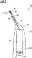
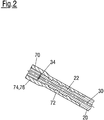
- FIG. 1 and 2 show sectional views of a housing 20 and an application tool 70, wherein Fig. 2 shows a detailed view of a front end 22 of the housing 20, on which the application tool 70 is arranged.
- Fig. 1 and 2 show sectional views of a housing 20 and an application tool 70, wherein Fig. 2 shows a detailed view of a front end 22 of the housing 20, on which the application tool 70 is arranged.
- Fig. 1 a sectional view of a housing 20 of an application device 10 according to the invention is shown. Additionally, already an application tool 70 is arranged on the front end 22 of the housing 10, preferably in a 2-component injection molding process. Especially preferred, the used material, both for the housing 20 and for the application tool 70, is plastic.
- the 2-component injection molding process allows providing the housing 20 and the application tool 70 as a single component, whereby the two sub-components can be made up from different materials.
- the material used for the application tool 70 can be softer and the material for the housing 20 can be more rigid, resulting in a solid housing 20 and an application tool 70, especially in an application tip 76 of the application tool 70, which is at least somewhat flexible and prevents the target surface to be harmed.
- a rear shaft 72 of the application tool 76 encloses the front end 22 region of the housing 20, providing a secure fixing of the application tool 70 on the housing 20.
- the application tool 70 especially comprising a rear shaft 22 on its rear end and the application tip 76 on its front end 74, encloses the front end 22 of the housing.
- An application channel 30 runs through the front end 22 of the housing 20, wherein the application tip 76 is placed at the application channel outlet 34. Grooves in the front end 22 of the housing 20 are filled with material of the application tool 70, therefore providing a secure fixing of the application tool 70.
- This arrangement can be easily and preferably be provided by using a 2-component injection molding process when producing the housing 20 and the application tool 70, wherein preferably as a first step the housing 20 is molded and subsequently as a second step the application tool 70 is molded onto the housing.
- part of the housing 20 as shown in Fig. 1 is an application channel 30, extending through the housing 20 from an application channel input port 32 to an application channel outlet 34.
- the application channel 30 is a linear extending channel.
- the application channel inlet port 32 ends well within the housing.
- a shielding section 60 extends well beyond the application channel inlet port 32, defining an inner volume 24 of the housing.
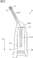
- Fig. 3 shows a connection section 40 of an application device 10 according to the invention, which is used to extend the application channel 30 in the inner volume 24 of the housing 20 shown in Fig. 1 .
- the connection section 40 comprises a connection channel 42 extending through the connection section 40 as preferably linear channel from a connection channel inlet port 44 to a connection channel outlet port 46.
- the connection channel outlet port 46 can be sealingly connected to the application channel inlet port 32, building a discharging channel 12 (not shown) in the application device 10 according to the invention.
- the connection section 40 is made using an injection molding process, wherein a usage of the same material as used for the housing 20 is especially preferred.
- connection section 40 comprises connecting means 48 for a connection to an outlet port 82 of a discharging device 80 (not shown).
- An additional sealing surface 50 of the connection means 48 is used to engage a respective sealing area 84 of the discharging device 80 (both not shown), providing a sealed connection of the connection section 40 and therefore of the application device 10 as a whole, to the discharging device 80. Leaking of fluid to be applicated and/or a contamination of the fluid to be applicated can therefore be prohibited.
- FIGs. 4 to 6 an application device 10 according to the invention is shown in different steps of assembling.
- Fig. 4 and 5 show sectional views
- Fig. 6 an isometric view of the fully assembled application device 10 according to the invention. In the following, these three Figures are therefore described together, wherein each Figure is addressed separately if necessary.
- Fig. 4 and 5 show the components of an application device 10 according to the invention as described in Fig. 1 to 4 .
- the connection section 40 is still placed outside of the inner volume 24 of the housing 20.
- the connection channel 42 of the connection section 40 and the application channel 30 of the housing 20 are separated.
- connection section 40 is positioned within the inner volume 24 of the housing 20, wherein the connection channel outlet port 46 is sealingly arranged at the application channel inlet port 32.
- Arranging the connection channel outlet port 46 on the application channel inlet port 32 can be preferably done by welding or gluing This forms a discharging channel 12 in the application device 10 according to the invention, extending from the connection channel inlet port 44 to the application channel outlet 34 in the application tip 74 of the application tool 70.
- connection channel 42 and the application channel 30 run obliquely to each other when the connection channel outlet port 46 is connected to the application channel inlet port 32.
- connection channel 42 and the application channel 30 are arranged in a kinked configuration. Therefore, target areas not reachable for application devices 10 with a completely straight channel can be reached. Especially for dental compounds this means that all areas within the mouth of a patent can be reached easily
- shielding section 60 stand apart from the connection section 40 and surrounds the connection section 40.
- the connection section 40 is shielded by the shielding section 60 from direct contact, especially manual direct contact.
- the shielding section 60 extends beyond the connection channel inlet port 44 in the direction 14 of the connection section 20 and the connection channel 42, respectively. This provides a connection channel inlet port 44 and the connection section 40 as a whole to be recessed and therefore protected within the inner volume 24. A manual contact especially of the discharging channel 12 and the risk of a contamination can therefore be lowered.
- Fig. 6 shows the assembled application device 10 according to the invention as shown in Fig. 5 in an isometric view.
- the connection section 40 is not visible and protected within the housing 20 by the shielding section 60 of the housing 20. It is therefore possible to manually touch the application device 10, especially the housing 20, without the risk of contamination of the fluid to be applicated through the application tip 74 of the application tool 70.
- a discharging device 80 in combination with an application device 10 according to the invention is shown.
- the application device 10 is securely fixed, especially using the connection means 48 on connection channel inlet port 44, concealed by the shielding section 60 of the housing 20.
- the application tool 70 is used to applicate the fluid to be applicated, wherein the discharging device 80 provides this fluid.
Landscapes
- Health & Medical Sciences (AREA)
- Epidemiology (AREA)
- Oral & Maxillofacial Surgery (AREA)
- Dentistry (AREA)
- Life Sciences & Earth Sciences (AREA)
- Animal Behavior & Ethology (AREA)
- General Health & Medical Sciences (AREA)
- Public Health (AREA)
- Veterinary Medicine (AREA)
- Mechanical Engineering (AREA)
- Manufacturing & Machinery (AREA)
- Engineering & Computer Science (AREA)
- Dental Tools And Instruments Or Auxiliary Dental Instruments (AREA)
Priority Applications (4)
| Application Number | Priority Date | Filing Date | Title |
|---|---|---|---|
| EP18208096.0A EP3656341A1 (fr) | 2018-11-23 | 2018-11-23 | Dispositif d'application et procédé de fabrication d'un dispositif d'application |
| US17/289,800 US20210393371A1 (en) | 2018-11-23 | 2019-11-14 | Application device and method for producing an application device |
| EP19809729.7A EP3849459A1 (fr) | 2018-11-23 | 2019-11-14 | Dispositif d'pplication et procédé de production d'un dispositif d'application |
| PCT/EP2019/081402 WO2020104298A1 (fr) | 2018-11-23 | 2019-11-14 | Dispositif d'pplication et procédé de production d'un dispositif d'application |
Applications Claiming Priority (1)
| Application Number | Priority Date | Filing Date | Title |
|---|---|---|---|
| EP18208096.0A EP3656341A1 (fr) | 2018-11-23 | 2018-11-23 | Dispositif d'application et procédé de fabrication d'un dispositif d'application |
Publications (1)
| Publication Number | Publication Date |
|---|---|
| EP3656341A1 true EP3656341A1 (fr) | 2020-05-27 |
Family
ID=64456870
Family Applications (2)
| Application Number | Title | Priority Date | Filing Date |
|---|---|---|---|
| EP18208096.0A Withdrawn EP3656341A1 (fr) | 2018-11-23 | 2018-11-23 | Dispositif d'application et procédé de fabrication d'un dispositif d'application |
| EP19809729.7A Withdrawn EP3849459A1 (fr) | 2018-11-23 | 2019-11-14 | Dispositif d'pplication et procédé de production d'un dispositif d'application |
Family Applications After (1)
| Application Number | Title | Priority Date | Filing Date |
|---|---|---|---|
| EP19809729.7A Withdrawn EP3849459A1 (fr) | 2018-11-23 | 2019-11-14 | Dispositif d'pplication et procédé de production d'un dispositif d'application |
Country Status (3)
| Country | Link |
|---|---|
| US (1) | US20210393371A1 (fr) |
| EP (2) | EP3656341A1 (fr) |
| WO (1) | WO2020104298A1 (fr) |
Citations (2)
| Publication number | Priority date | Publication date | Assignee | Title |
|---|---|---|---|---|
| US20020160333A1 (en) * | 2000-10-13 | 2002-10-31 | Dentsply Research & Development Corp. | Multi-component mixing storage and dispensing device |
| CN208017613U (zh) * | 2017-12-12 | 2018-10-30 | 苏州墨嫣贸易有限公司 | 一种电动口腔清洁器 |
Family Cites Families (5)
| Publication number | Priority date | Publication date | Assignee | Title |
|---|---|---|---|---|
| DE102009013000A1 (de) * | 2009-03-13 | 2010-09-16 | Kaltenbach & Voigt Gmbh | Handgerät zur Abgabe einer pastösen Füllmasse |
| WO2013174549A1 (fr) * | 2012-05-24 | 2013-11-28 | Sulzer Mixpac Ag | Mélangeur pour mélanger au moins deux composants fluides |
| US9956057B2 (en) * | 2013-02-15 | 2018-05-01 | Pheneo Gmbh | Method for manufacturing a cartridge for containing and meterably dispensing a flowable dental material and such a cartridge |
| EP3106122A1 (fr) * | 2015-06-17 | 2016-12-21 | 3M Innovative Properties Company | Systeme comprenant un melangeur statique et dispositif de distribution pour des materiaux dentaires |
| EP3406331A1 (fr) * | 2017-05-24 | 2018-11-28 | 3M Innovative Properties Company | Mélangeur destiné à distribuer un matériau à composants multiples |
-
2018
- 2018-11-23 EP EP18208096.0A patent/EP3656341A1/fr not_active Withdrawn
-
2019
- 2019-11-14 US US17/289,800 patent/US20210393371A1/en not_active Abandoned
- 2019-11-14 WO PCT/EP2019/081402 patent/WO2020104298A1/fr not_active Ceased
- 2019-11-14 EP EP19809729.7A patent/EP3849459A1/fr not_active Withdrawn
Patent Citations (2)
| Publication number | Priority date | Publication date | Assignee | Title |
|---|---|---|---|---|
| US20020160333A1 (en) * | 2000-10-13 | 2002-10-31 | Dentsply Research & Development Corp. | Multi-component mixing storage and dispensing device |
| CN208017613U (zh) * | 2017-12-12 | 2018-10-30 | 苏州墨嫣贸易有限公司 | 一种电动口腔清洁器 |
Also Published As
| Publication number | Publication date |
|---|---|
| WO2020104298A1 (fr) | 2020-05-28 |
| US20210393371A1 (en) | 2021-12-23 |
| EP3849459A1 (fr) | 2021-07-21 |
Similar Documents
| Publication | Publication Date | Title |
|---|---|---|
| CN104755131B (zh) | 包覆成型的医用连接器管和方法 | |
| CN101405050B (zh) | 安全连接器组件 | |
| AU2022204746B2 (en) | Physiological signal monitoring device | |
| JP6983655B2 (ja) | 2材料製yコネクタ | |
| CA2905434C (fr) | Ensemble catheter | |
| EP1566193A1 (fr) | Dispositif d'injection avec logement pour le septum | |
| WO2004032707A3 (fr) | Site d'injection pour connecteur luer male ou autre connecteur tubulaire | |
| PL1755690T3 (pl) | Urządzenie sterylizujące do sterylizacji cieczy | |
| AU2003239334A1 (en) | A disposable needle assembly having sensors formed therein permitting the simultaneous drawing and administering of fluids and method of forming the same | |
| WO2002045771A3 (fr) | Adaptateur pour micro-aiguilles | |
| WO2003009884A3 (fr) | Seringue allongee | |
| AU6151799A (en) | Self-cleaning fluid delivery device for medical applications | |
| TW200603895A (en) | Fluid discharging device | |
| JP6853337B2 (ja) | 医療技術的測定装置、及び測定方法 | |
| US20210393371A1 (en) | Application device and method for producing an application device | |
| US4413992A (en) | Cannula support assembly and its method of manufacture | |
| TW200716451A (en) | Device for administering medical liquids and method for the manufacturing thereof | |
| EP3656340A1 (fr) | Dispositif d'application et procédé de fabrication d'un dispositif d'application | |
| RU2751967C2 (ru) | Устройство проточного сообщения и криозонд с таким устройством проточного сообщения | |
| JP5000724B2 (ja) | 流体接続用針インターフェース | |
| FR2884896B1 (fr) | Raccord d'etancheite et ensemble d'un organe de transmission, d'une cartouche de gaz et d'un adaptateur comprenant le raccord | |
| CN209173217U (zh) | 一种医用三通保护壳 | |
| WO2020152094A1 (fr) | Capsule de composés à faible et/ou haute viscosité, piston destiné à une utilisation avec une capsule et système comprenant une capsule et un piston | |
| CN120077221A (zh) | 具有防泄漏偏移分型线的模制活塞密封件 | |
| WO2021039624A1 (fr) | Goutteur et tuyau d'irrigation goutte à goutte |
Legal Events
| Date | Code | Title | Description |
|---|---|---|---|
| PUAI | Public reference made under article 153(3) epc to a published international application that has entered the european phase |
Free format text: ORIGINAL CODE: 0009012 |
|
| STAA | Information on the status of an ep patent application or granted ep patent |
Free format text: STATUS: THE APPLICATION HAS BEEN PUBLISHED |
|
| AK | Designated contracting states |
Kind code of ref document: A1 Designated state(s): AL AT BE BG CH CY CZ DE DK EE ES FI FR GB GR HR HU IE IS IT LI LT LU LV MC MK MT NL NO PL PT RO RS SE SI SK SM TR |
|
| AX | Request for extension of the european patent |
Extension state: BA ME |
|
| STAA | Information on the status of an ep patent application or granted ep patent |
Free format text: STATUS: THE APPLICATION IS DEEMED TO BE WITHDRAWN |
|
| 18D | Application deemed to be withdrawn |
Effective date: 20201128 |