EP3656494A1 - Stufenbohrer - Google Patents
Stufenbohrer Download PDFInfo
- Publication number
- EP3656494A1 EP3656494A1 EP19193507.1A EP19193507A EP3656494A1 EP 3656494 A1 EP3656494 A1 EP 3656494A1 EP 19193507 A EP19193507 A EP 19193507A EP 3656494 A1 EP3656494 A1 EP 3656494A1
- Authority
- EP
- European Patent Office
- Prior art keywords
- drill
- drilling
- longitudinal axis
- suction
- boring
- Prior art date
- Legal status (The legal status is an assumption and is not a legal conclusion. Google has not performed a legal analysis and makes no representation as to the accuracy of the status listed.)
- Granted
Links
Images


Classifications
-
- B—PERFORMING OPERATIONS; TRANSPORTING
- B23—MACHINE TOOLS; METAL-WORKING NOT OTHERWISE PROVIDED FOR
- B23B—TURNING; BORING
- B23B51/00—Tools for drilling machines
- B23B51/009—Stepped drills
-
- B—PERFORMING OPERATIONS; TRANSPORTING
- B23—MACHINE TOOLS; METAL-WORKING NOT OTHERWISE PROVIDED FOR
- B23B—TURNING; BORING
- B23B51/00—Tools for drilling machines
- B23B51/0002—Drills with connected cutting heads, e.g. with non-exchangeable cutting heads; Drills with a single insert extending across the rotational axis and having at least two radially extending cutting edges in the working position
- B23B51/0003—Drills with connected cutting heads, e.g. with non-exchangeable cutting heads; Drills with a single insert extending across the rotational axis and having at least two radially extending cutting edges in the working position with exchangeable heads or inserts
- B23B51/00035—Spade drills
-
- B—PERFORMING OPERATIONS; TRANSPORTING
- B23—MACHINE TOOLS; METAL-WORKING NOT OTHERWISE PROVIDED FOR
- B23B—TURNING; BORING
- B23B2226/00—Materials of tools or workpieces not comprising a metal
- B23B2226/75—Stone, rock or concrete
-
- B—PERFORMING OPERATIONS; TRANSPORTING
- B23—MACHINE TOOLS; METAL-WORKING NOT OTHERWISE PROVIDED FOR
- B23B—TURNING; BORING
- B23B2251/00—Details of tools for drilling machines
- B23B2251/50—Drilling tools comprising cutting inserts
-
- B—PERFORMING OPERATIONS; TRANSPORTING
- B23—MACHINE TOOLS; METAL-WORKING NOT OTHERWISE PROVIDED FOR
- B23B—TURNING; BORING
- B23B2251/00—Details of tools for drilling machines
- B23B2251/68—Drills with provision for suction
Definitions
- the invention relates to a step drill according to the preamble of claim 1 and a method for producing a step drill according to claim 15.
- the step drill in question is particularly suitable for drilling in concrete or reinforced concrete, but also in other masonry, rock or the like. It is intended for use in conjunction with a hammer, impact and / or rotary drilling device.
- the step drill has an insertion section for coupling with the respective drilling device. This is followed by the drill shank and finally the drill head.
- a well-known step drill ( US 9,434,009 B2 ), from which the invention is based, has a drill head with a pre-drilling step for drilling a borehole with a first diameter and with a drilling step for expanding the borehole drilled with the pre-drilling step to a larger diameter.
- the boring stage is offset from the pre-boring stage along the longitudinal axis of the step drill.
- the step drill has a suction channel arrangement with a suction channel.
- the cutting edge of the pre-drilling step and also the cutting edge of the boring step are each formed by the base body of the step drill itself, that is, they are formed integrally with the base body.
- the cutting edges of the pre-boring stage and the boring stage are subject to comparatively great wear, which is why the basic aim of drills is to improve their service life.
- the invention is based on the problem of designing and developing the known step drill in such a way that its service life is improved.
- the fundamental consideration is to provide separate cutting inserts for the predrilling and boring stages.
- cutting inserts By using cutting inserts to form the cutting edge, considerably harder materials can be used, thus reducing the wear on the drill and improving its service life accordingly.
- the drilling speed can also be increased.
- such a step drill can be produced particularly inexpensively, since only the cutting inserts have to be formed from a particularly hard and resistant material. As a result, the drill can also be produced inexpensively.
- a cutting edge of the pre-drilling step is formed by at least one cutting insert, that a cutting edge of the drilling step is formed by at least one separate cutting insert, and that the cutting inserts are arranged on a base body comprising the drill head.
- the base body of the step drill has receptacles for the cutting inserts.
- the stepped drill and in particular the suction channel arrangement according to at least one of the features of claims 3 to 6.
- the extraction of the drilling dust through the interior of the step drill instead of removal through one or more external spiral grooves and the specific described arrangements of the extraction openings enable particularly effective extraction of the drilling dust produced during drilling.
- Claims 13 and 14 describe preferred structures of the step drill. These enable the same to be manufactured easily and inexpensively.
- a method for producing a step drill in which a longitudinal bore running along the longitudinal axis of the drill is drilled, in particular deep-drilled, and in which a transverse bore angled to the longitudinal axis of the drill is drilled in the basic body is drilled in such a way that the longitudinal bore and the transverse bore are connected to one another.
- a longitudinal bore running along the longitudinal axis of the drill is drilled, in particular deep-drilled, and in which a transverse bore angled to the longitudinal axis of the drill is drilled in the basic body is drilled in such a way that the longitudinal bore and the transverse bore are connected to one another.
- Claim 16 relates to the production of receptacles for the cutting inserts and the insertion thereof in the receptacles.
- step drill 1 with a drill shaft 2, with an insertion end 3 and an end of the drill shaft 2 facing away from the insertion end 3 is shown.
- the step drill 1 is a rock drill which is suitable for the processing of concrete or reinforced concrete, masonry, rock or the like.
- the drill head 4 has a pre-drilling step 5 for drilling a borehole with a first diameter. Furthermore, the drill head has at least one boring stage 6 for expanding a borehole drilled with the predrilling stage 5 to a larger diameter.
- the boring stage 6 is here offset from the predrilling stage 5 along a longitudinal axis B of the drill, as shown in FIG Fig. 1 is shown.
- the longitudinal axis B of the drill corresponds to the axis of rotation of the step drill 1 during drilling.
- the step drill 1 has at least one suction channel arrangement 7 with at least one suction channel 8, which leads from at least one suction opening 9 of the drill head 4 through the interior of the drill shaft 2 to an outlet opening 10 for discharging drilling dust to a suction device 11.
- the drilling dust generated during drilling can be sucked off particularly effectively and with as little strain on the environment as possible.
- a cutting edge 12 of the predrilling step 5 is formed by at least one cutting insert 13. It is also provided that a cutting edge 14 of the boring step 6 is formed by at least one separate cutting insert 15.
- the use of cutting inserts 13, 15 in the pre-drilling step 5 and in the boring step 6 enables cost-effective production of the step drill 1, a long service life of the step drill 1 and an increased drilling speed.
- a drilling step 5, 6 is considered here and preferably as the device that removes material.
- the pre-drilling step 5 is formed by the cutting edges 12 of the cutting insert 13 and the boring step by the cutting edges 14 of the cutting inserts 15.
- the step drill 1 can also have further boring steps, not shown, which allow further enlargements of the diameter of the borehole.
- the step drill 1 has a drill body 2, the insertion end 3 and the drill head 4 having the base body 16, which is provided here with receptacles 17 for the cutting inserts 13, 15.
- the base body 16 has a first and a second axial, here and preferably cylindrical, section 18, 19.
- the sections 18, 19 together form the drill head 4.
- Each of the sections 18, 19 has at least one receptacle 17 for the respective cutting insert 13, 15.
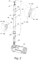
- the first sections 18 and the second section 19 have a different radius R 1 , R 2 , as shown in FIG Fig. 2 is shown.
- the radius R 1 of the first section 18, which has the receptacle for the respective cutting insert 13 of the predrilling step 5, is smaller than the radius R 2 of the second section 19, which has the receptacle 17 for the respective cutting insert 15 of the drilling step 6.
- the radial distance between the radially outermost point or the radially outermost edge of the respective cutting insert 13, 15 and the longitudinal axis B for the respective cutting insert 13 of the predrilling stage 5 is smaller than for the respective cutting insert 15 of the boring stage 6.
- the base body 16 can also have only one axial, in particular cylindrical, section, which has, in particular completely, the receptacles for the cutting inserts 13, 15 of the pre-drilling step 5 and the drilling step 6.
- the diameter of this one section is then preferably essentially constant.
- the receptacles 17 for the cutting inserts are as in the Fig. 2 shown, formed by receiving grooves. In this case, they can be produced particularly easily and inexpensively using a milling tool.
- the receptacles 17 for the cutting inserts 15 of the boring stage 6 are formed in the first and the second section 18, 19 in the exemplary embodiment.
- the cutting inserts 15 of the boring stage 6 are arranged in the region of the transition between the two sections 18, 19.
- the receptacles 17 preferably extend to at least 50%, more preferably to at least 80%, over the second section 19. As a result, the cutting inserts of the boring step 6 are held firmly and securely in the step drill 1 and are supported with respect to the drilling forces.
- the removal of drilling dust from the drill head 4 takes place here and preferably through the suction channel arrangement 7, so that the removal is thus carried out through the interior of the drill shaft 2.
- the drill shaft 2 is part of the base body 16 here.
- the step drill is designed without a spiral groove.
- the step drill particularly preferably has no external removal grooves for the drilling dust.
- the surface of the base body 16 is essentially flat-cylindrical. However, it can have cylindrical sections of different radii, as shown in the figures.
- At least one suction opening 9 is a pre-drilling step suction opening 9a arranged in the region of the pre-drilling step 5.
- the pre-drilling step suction opening 9a has its opening essentially in the axial direction of the step drill 1.
- the pre-drilling step suction opening 9a is arranged on the end face 20 of the drilling head 4.
- at least exactly one pre-drilling stage suction opening 9a is arranged on both sides of the respective - in the exemplary embodiment - a cutting insert 13 of the pre-drilling stage 5.
- the two pre-drilling step suction openings 9a of the exemplary embodiment are each formed by a suction hole 21 in the end face 20 of the step drill 1.
- the pre-drilling step suction openings 9a can also point with their opening in a radial direction of the step drill 1 or additional ones Pre-drilling step suction openings 9a can be provided which point with their opening in a radial direction of the step drill 1.
- no suction openings 9 are provided in the area of the boring step 6.
- all of the suction openings are 9 pre-drilling step suction openings 9. These enable particularly effective removal of drilling dust from the borehole. Because only suction openings 9 are provided in the area of the pre-drilling step, the entire suction pressure for suctioning drilling dust is built up at the pre-drilling step 5. The drilling dust produced at the boring stage 6 can, if necessary, be sucked along the first section 18 of the base body 16, which has the receptacle 17 for the respective cutting insert 13 of the pre-boring stage 5, to the pre-boring stage suction openings 9a and then removed from the borehole by the suction channel arrangement 7 will.
- a channel can arise between the outer surface of the base body 16 and the material inside of the borehole, through which the drilling dust in the direction of drilling to the pre-drilling stage suction opening 9a or the pre-drilling stage suction openings 9a and there is sucked into the suction channel 8.
- one or more channels, via which the drilling dust is guided in the drilling direction to the pre-drilling stage suction opening 9a or the pre-drilling stage suction openings 9a, can be formed by radially outer-side discharge grooves in the first section 18, which are in particular exclusively in the first section 18 extend and preferably run parallel to the longitudinal axis B.
- At least one suction opening 9 can be a drilling-step suction opening 9b provided in the region of the boring step 6.
- the boring step suction device 9b is here and preferably a suction opening 9 directed in a radial direction of the step drill 1.
- This optional boring step suction opening 9b is shown schematically in broken lines in FIG Fig. 1 shown.
- the boring stage suction opening 9b viewed from the drilling tip 22, is provided in the axial direction behind an axial cutting edge 14 of at least one cutting insert 15 of the boring stage.
- the Boring-stage suction opening 9b is thus completely arranged in section 19 of base body 16, which has the larger radius R 2 . It preferably does not pass into the first section 18 of the base body 16, which has the smaller radius R 1 .
- the radius R 1 can be, for example, 5 mm and the radius R 2 can be, for example, 6 mm.
- boring stage suction openings 9b are preferably arranged at the same angular distance around the longitudinal axis B of the drill.
- two boring stage suction openings 9b are provided. They are diametrically opposite.
- the boring stage suction openings 9b are arranged here at an angular distance of 90 ° to the cutting inserts 15 of the boring stage 6.
- the pre-drilling stage 5 has only one cutting insert 13.
- the cutting insert 13 of the predrilling step 5 forms the drill tip 22.
- the cutting insert 13 has at least one substantially axially acting cutting edge 12a and at both ends thereof a radially acting cutting edge 12b.
- the boring stage 6 has in the embodiment of the Figures 1 and 2nd exactly two cutting inserts 15. It preferably has at least, in particular exactly, one cutting insert 15, preferably at least, in particular exactly, two cutting inserts 15 or at least, in particular exactly, three cutting inserts 15. In addition, further cutting inserts 15 can also be provided.
- the respective cutting insert 15 of the boring stage here and preferably has a substantially axially acting cutting edge 14a and a, in particular exactly one, radially acting cutting edge 14b.
- the cutting inserts 15 of the boring stage 6 are preferably arranged at the same angular distance around the longitudinal axis B of the drill. They are preferably arranged symmetrically around the longitudinal axis B of the drill, as in FIG Embodiment of the Fig. 1 with the diametrically opposed cutting inserts 15 is the case.
- the cutting insert 13 of the predrilling step 5 when the step drill 1 is projected in the direction of the drill longitudinal axis B, the cutting insert 13 of the predrilling step 5 extends along a longitudinal axis L which is orthogonal to the drill longitudinal axis B. This is in the Fig. 4 shown. If the pre-drilling step 5 has a plurality of cutting inserts 13 (not shown here), the cutting inserts 13 of the pre-drilling step 5 are preferably arranged on a longitudinal axis which is orthogonal to the longitudinal axis B of the drill.
- the cutting inserts 15 of the boring stage 6 are arranged here and preferably on the longitudinal axis L.
- the center lines of the cutting inserts 15 of the boring step 6 and the center lines of the cutting inserts 13 of the predrilling step 5 run particularly preferably on this longitudinal axis L. This enables particularly simple production to be achieved.
- This arrangement of the cutting inserts 13, 15 can overall produce an out-of-round borehole (polygon) which, due to its geometry, provides a particularly high dowel pull-out value.
- This has the advantage that the non-circular borehole produced by the predrilling step 5 is expanded in the same way by the drilling step 6.
- the cutting inserts 15 of the boring stage 6 thus produce essentially the same, but enlarged, borehole shape and borehole orientation as the cutting inserts 13 of the predrilling stage 5 in cross section to the longitudinal axis B.
- Fig. 4b extends the cutting insert of the pilot hole in a projection of the step drill 1 in the direction of the longitudinal axis B along a longitudinal axis L, which is orthogonal to the longitudinal axis B.
- the cutting inserts 13 of the pre-drilling step 5 are preferably arranged on a longitudinal axis which is orthogonal to the longitudinal axis B of the drill.
- the central axes of the cutting inserts 15 of the boring stage 6 on a connecting straight line V is preferably arranged at an angle to the connecting straight line V.
- the longitudinal axis L arranged at an angle of 90 ° to the connecting line V.
- FIG. 4c Another embodiment is in the Fig. 4c shown.
- a single cutting insert 13 is provided for the pre-drilling stage.
- further cutting inserts 13 in the predrilling stage 5 are also conceivable here.
- three cutting inserts 15 are provided. These are arranged here and preferably at a uniform angular distance around the longitudinal axis B. In the exemplary embodiment, the angular distance is 120 °. It is particularly advantageous if they are arranged offset to a longitudinal axis L of the cutting insert 13 of the predrilling stage 5, which is orthogonal to the longitudinal axis B of the drill. With this configuration, particularly round drill holes can also be produced.
- the cutting inserts 13, 15 are located radially beyond the base body 16 in the region of their receptacle 17.
- the respective cutting insert 13 of the predrilling stage 5 projects radially beyond the base body 16 in the region of its receptacle 17 from 0.1 mm to 1.5 mm.
- the respective cutting insert 15 of the boring step 6 preferably projects 0.2 mm to 1 mm beyond the base body 16 in the area of its receptacle 17.
- the cutting inserts 13 of the predrilling step 5 and the cutting inserts 15 of the drilling step 6 are particularly preferably at different distances beyond the base body 16.
- the respective The cutting insert 13 of the predrilling step 5 protrude further beyond the base body 16 than the respective cutting insert 15 of the boring step 6.
- the drill head 4 of the stepped drill 1 is preferably axially symmetrical and / or rotationally symmetrical about the longitudinal axis B of the drill.
- the step drill 1 has a suction section 23.
- the suction section 23 is formed integrally by the base body 16.
- the base body 16 is made in one piece with the first section 18, optionally with the second section 19, and with the suction section 23.
- the suction section 23 has a larger radius than the predominant part of the second section 19.
- the suction section 23 has a transverse bore 24, which forms a section of the suction channel arrangement 7 and provides the outlet opening 10 for discharging the drilling dust from the step drill 1. This outlet opening 10 is arranged in the suction section 23.
- a suction adapter 25 which has a, in particular radial, connection piece for connecting a suction device 11, for example an electric vacuum cleaner.
- the suction adapter 25 is connected here to the suction section 23 of the step drill 1 and is arranged axially spaced from the drill head 4.
- the transverse bore 24 opens into the suction adapter 25, in particular into a chamber K of the suction adapter 25 that runs around the suction section 23.
- the suction section 23 of the step drill 1 can be rotated relative to the suction adapter 25.
- the step drill 1 can have a clamping section 26 at the insertion end 3.
- the clamping section 26 is designed as an SDS section, in particular as an SDS-plus or SDSmax section, for reception by the drill chuck of an impact drill. Basically, this can also be designed purely cylindrical for inclusion in a chuck.
- the diameter of the clamping section 26 is here and preferably smaller than that of the Suction section 23.
- the clamping section 26 is formed integrally with the base body 16. Incidentally, it is made from one piece together with the basic body. Alternatively, the clamping section 26 can, however, also be produced separately from the base body 16 and joined, in particular soldered or screwed, to the base body 16 and / or the suction section 23.
- the base body 16 is drilled, in particular deep-drilled.
- This bore of the suction channel arrangement 7 is designed as a longitudinal bore 27. It preferably runs essentially in the direction of the longitudinal axis B. Preferably, it runs parallel, here coaxial to the longitudinal axis B. It is also conceivable for the longitudinal bore 27 to be inclined to the longitudinal axis B. Deep hole drilling is generally referred to when its length is at least 15 times its diameter.
- the hole is designed as a blind hole. It opens here and preferably in the transverse bore 24, in particular in its closed end.
- the transverse bore 24 here and preferably has a larger diameter than the longitudinal bore 27.
- the transverse bore 24 is preferably directed at an angle to the longitudinal bore 27 and / or longitudinal axis B of the drill, in particular it has an angle of 120 ° to 150 °, preferably 135 ° to the longitudinal bore . It is designed here and preferably as a blind hole.
- the base body 16 has one or more, in particular two, suction bores 21 which provide the suction openings 9 of the predrilling stage 5.
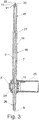
- these are as in FIG Fig. 3 shown formed as blind holes. They run here and preferably parallel to the longitudinal bore 27. In the exemplary embodiment, they overlap in cross section with the longitudinal bore 27, as in FIG Fig. 4 shown.
- Their depth is preferably one to five times the length of the extension along the longitudinal axis B of the respective cutting inserts 13 of the pre-drilling step 5.
- each suction opening 9 formed by the longitudinal bore 27 is not produced by a separately produced suction bore 21.
- the receptacles 17, in particular in the form of receiving grooves, for the cutting inserts 13, 15 of the pre-drilling step 5 and the boring step 6 are preferably produced in one operation.
- the receptacles 17 for the cutting inserts 13, 15 of the predrilling stage 5 and the boring stage 6, in particular their central axes, lie orthogonally to the longitudinal axis B of the drill in one plane. Further preferably, the longitudinal axis B of the drill lies in this plane.
- the production in one work step is characterized, for example, in that the receptacles are produced in one setting and / or without changing tools. Additionally or alternatively, the production in one work step can mean that the receptacles are produced in parallel and / or are produced in the same working stroke. Alternatively, it is of course also conceivable to produce the receiving grooves in separate operations.
- the receptacle 17 of the predrilling step 5 is first produced, and then the receptacles 17 of the drilling step 6 are produced in a working stroke.
Landscapes
- Engineering & Computer Science (AREA)
- Mechanical Engineering (AREA)
- Processing Of Stones Or Stones Resemblance Materials (AREA)
Abstract
Description
- Die Erfindung betrifft einen Stufenbohrer gemäß dem Oberbegriff von Anspruch 1 sowie ein Verfahren zur Herstellung eines Stufenbohrers gemäß Anspruch 15.
- Der in Rede stehende Stufenbohrer eignet sich insbesondere für das Bohren in Beton oder Stahlbeton, aber auch in sonstigem Mauerwerk, Fels oder dergleichen. Er ist für den Einsatz in Verbindung mit einer Hammer-, Schlag- und/oder Drehbohrvorrichtung vorgesehen. Für die Kopplung mit der jeweiligen Bohrvorrichtung weist der Stufenbohrer einen Einsteckabschnitt auf. Daran schließt sich der Bohrerschaft und schließlich der Bohrkopf an.
- Ein bekannter Stufenbohrer (
US 9,434,009 B2 - Die Schneiden der Vorbohrstufe und der Aufbohrstufe unterliegen einem vergleichsweise großen Verschleiß, weshalb grundsätzlich bei Bohrern angestrebt wird, ihre Standzeit zu verbessern.
- Der Erfindung liegt das Problem zugrunde, den bekannten Stufenbohrer derart auszugestalten und weiterzubilden, dass dessen Standzeit verbessert wird.
- Das obige Problem wird bei einem Stufenbohrer gemäß dem Oberbegriff von Anspruch 1 durch die Merkmale des kennzeichnenden Teils von Anspruch 1 gelöst.
- Wesentlich ist die grundsätzliche Überlegung, separate Schneideinsätze für die Vorbohrstufe und die Aufbohrstufe vorzusehen. Durch die Verwendung von Schneideinsätzen zum Ausbilden der Schneide können erheblich härtere Materialien verwendet werden und so der Verschleiß des Bohrers reduziert und seine Standzeit entsprechend verbessert werden. Auch kann die Bohrgeschwindigkeit gesteigert werden. Zudem lässt sich ein solcher Stufenbohrer besonders kostengünstig herstellen, da nur die Schneideinsätze aus einem besonders harten und widerstandsfähigen Material gebildet werden müssen. Hierdurch ist der Bohrer zudem kostengünstig produzierbar.
- Im Einzelnen wird vorgeschlagen, dass eine Schneide der Vorbohrstufe durch mindestens einen Schneideinsatz gebildet wird, dass eine Schneide der Aufbohrstufe durch mindestens einen separaten Schneideinsatz gebildet wird und dass die Schneideinsätze an einem den Bohrkopf umfassenden Grundkörper angeordnet sind.
- In einer Weiterbildung der Erfindung gemäß Anspruch 2 weist der Grundkörper des Stufenbohrers Aufnahmen für die Schneideinsätze auf. Durch einen solchen Aufbau des Stufenbohrers kann dieser besonders günstig in verschiedenen Varianten hergestellt werden, indem der Grundkörper entsprechend den jeweiligen Anforderung angepasst gefertigt wird. Je nach Ausgestaltung und Bohrlochgeometrieziel sind verschiedene Ausgestaltungen des Grundkörpers und der Anordnung der Schneideinsätze vorteilhaft.
- Um beim Bohren die Umgebung mit möglichst wenig Bohrmehl zu belasten sowie die Standzeit und die Bohrgeschwindigkeit weiter zu verbessern, wird vorgeschlagen, den Stufenbohrer und insbesondere die Absaugkanalanordnung gemäß zumindest einem der Merkmale der Ansprüche 3 bis 6 auszubilden. Insbesondere das Absaugen des Bohrmehls durch das Innere des Stufenbohrers anstelle eines Abführens durch eine oder mehrere außenliegende Wendelnuten sowie die spezifischen beschriebenen Anordnungen der Absaugöffnungen ermöglichen ein besonders effektives Absaugen des beim Bohren entstehenden Bohrmehls.
- In den Ansprüchen 7 bis 12 sind bevorzugte Ausgestaltungen der Vorbohrstufe beziehungsweise der Aufbohrstufe sowie bevorzugte Anordnungen der Schneideinsätze am Stufenbohrer beschrieben. Durch entsprechende Anordnungen kann die Geometrie einer Bohrung beeinflusst werden.
- Die Ansprüche 13 und 14 beschreiben bevorzugte Aufbauten des Stufenbohrers. Diese ermöglichen eine einfache und kostengünstige Fertigung deselben.
- Nach einer weiteren Lehre gemäß Anspruch 15, der eigenständige Bedeutung zukommt, wird ein Verfahren zur Herstellung eines Stufenbohrers beansprucht, bei dem eine entlang der Bohrerlängsachse verlaufende Längsbohrung in den Grundkörper gebohrt, insbesondere tieflochgebohrt, wird und bei dem eine zur Bohrerlängsachse winklige Querbohrung in den Grundkörper gebohrt wird, derart, dass die Längsbohrung und die Querbohrung miteinander verbunden sind. Es darf auf alle Ausführungen zu dem vorschlagsgemäßen Stufenbohrer verwiesen werden.
- Anspruch 16 betrifft die Herstellung von Aufnahmen für die Schneideinsätze und das Einsetzen selbiger in die Aufnahmen.
- Im Folgenden wird die Erfindung anhand einer lediglich Ausführungsbeispiele darstellenden Zeichnung näher erläutert. In der Zeichnung zeigt
- Fig. 1
- eine dreidimensionale Darstellung eines vorschlagsgemäßen Stufenbohrers in einer perspektivischen Ansicht,
- Fig. 2
- eine Explosionsdarstellung des Stufenbohrers aus
Fig. 1 , - Fig. 3
- eine Schnittansicht des Stufenbohrers gemäß
Fig. 1 und - Fig. 4
- a) eine Aufsicht auf die Bohrerspitze des Stufenbohrers aus
Fig. 1 , b) eine Aufsicht gemäß eines weiteren Ausführungsbeispiels und c) eine Aufsicht gemäß noch eines weiteren Ausführungsbeispiels. - In der
Fig. 1 ist ein Stufenbohrer 1 mit einem Bohrerschaft 2, mit einem Einsteckende 3 und einem an dem Einsteckende 3 abgewandten Ende des Bohrerschafts 2 angeordneten Bohrkopf 4 gezeigt. Im Ausführungsbeispiel handelt es sich bei dem Stufenbohrer 1 um einen Gesteinsbohrer, welcher sich für die Bearbeitung von Beton oder Stahlbeton, Mauerwerk, Fels oder dergleichen eignet. - Der Bohrkopf 4 weist eine Vorbohrstufe 5 zum Bohren eines Bohrloches mit einem ersten Durchmesser auf. Ferner weist der Bohrkopf mindestens eine Aufbohrstufe 6 zum Erweitern eines mit der Vorbohrstufe 5 gebohrten Bohrloches auf einen größeren Durchmesser auf. Die Aufbohrstufe 6 ist hier zur Vorbohrstufe 5 entlang einer Bohrerlängsachse B versetzt angeordnet, wie dies in der
Fig. 1 gezeigt ist. Die Bohrerlängsachse B entspricht hier der Rotationsachse des Stufenbohrers 1 beim Bohren. - Ferner weist der Stufenbohrer 1 mindestens eine Absaugkanalanordnung 7 mit mindestens einem Absaugkanal 8 auf, der von mindestens einer Absaugöffnung 9 des Bohrkopfs 4 durch das Innere des Bohrerschafts 2 zu einer Austrittsöffnung 10 zum Abführen von Bohrmehl zu einer Absaugeinrichtung 11 führt. Hierdurch kann das beim Bohren entstehende Bohrmehl besonders effektiv und unter möglichst geringer Belastung der Umgebung abgesaugt werden.
- Erfindungsgemäß wird eine Schneide 12 der Vorbohrstufe 5 durch mindestens einen Schneideinsatz 13 gebildet. Ferner ist vorgesehen, dass eine Schneide 14 der Aufbohrstufe 6 durch mindestens einen separaten Schneideinsatz 15 gebildet wird. Die Verwendung von Schneideinsätzen 13, 15 in der Vorbohrstufe 5 und in der Aufbohrstufe 6 ermöglicht eine kostengünstige Produktion des Stufenbohrers 1, eine hohe Standzeit des Stufenbohrers 1 sowie eine gesteigerte Bohrgeschwindigkeit.
- Eine Bohrstufe 5, 6 wird hier und vorzugsweise als die Einrichtung betrachtet, welche Material abträgt. Im Ausführungsbeispiel wird die Vorbohrstufe 5 durch die Schneiden 12 des Schneideinsatz 13 gebildet und die Aufbohrstufe durch die Schneiden 14 der Schneideinsätze 15.
- Der Stufenbohrer 1 kann darüber hinaus weitere, nicht gezeigte, Aufbohrstufen aufweisen, welche weitere Erweiterungen des Durchmessers des Bohrlochs ermöglichen.
- Die Schneide 12 beziehungsweise Schneiden 12 der Vorbohrstufe 5 bilden hier und vorzugsweise die Hauptschneide, während die Schneide 14 beziehungsweise die Schneiden 14 der Aufbohrstufe 6 Nebenschneiden bilden.
- Wie der Explosionsdarstellung der
Fig. 2 entnommen werden kann, weist der Stufenbohrer 1 einen den Bohrerschaft 2, das Einsteckende 3 und den Bohrkopf 4 aufweisenden Grundkörper 16 auf, der hier mit Aufnahmen 17 für die Schneideinsätze 13, 15 versehen ist. Hier und vorzugsweise weist der Grundkörper 16 einen ersten und einen zweiten axialen, hier und vorzugsweise zylindrischen, Abschnitt 18, 19 auf. Die Abschnitte 18, 19 bilden hier zusammen den Bohrkopf 4. Je einer der Abschnitte 18, 19 weist mindestens eine Aufnahme 17 für den jeweiligen Schneideinsatz 13, 15 auf. - Der erste Abschnitte 18 und der zweite Abschnitt 19 weisen einen unterschiedlichen Radius R1, R2 auf, wie dies in der
Fig. 2 gezeigt ist. Der Radius R1 des ersten Abschnitts 18, welcher die Aufnahme für den jeweiligen Schneideinsatz 13 der Vorbohrstufe 5 aufweist, ist kleiner, als der Radius R2 des zweiten Abschnitts 19, welcher die Aufnahme 17 für den jeweiligen Schneideinsatz 15 der Aufbohrstufe 6 aufweist. - Auch ist der radiale Abstand zwischen dem radial äußersten Punkt bzw. der radial äußersten Kante des jeweiligen Schneideinsatzes 13, 15 und der Bohrerlängsachse B für den jeweiligen Schneideinsatz 13 der Vorbohrstufe 5 kleiner als für den jeweiligen Schneideinsatz 15 der Aufbohrstufe 6.
- Alternativ kann der Grundköper 16 auch nur einen axialen, insbesondere zylindrischen, Abschnitt aufweisen, welcher die Aufnahmen für die Schneideinsätze 13, 15 der Vorbohrstufe 5 sowie der Aufbohrstufe 6, insbesondere vollständig, aufweist. Der Durchmesser dieses einen Abschnitts ist dann vorzugsweise im Wesentlichen konstant.
- Die Aufnahmen 17 für die Schneideinsätze werden wie in der
Fig. 2 gezeigt, durch Aufnahmenuten gebildet. In diesem Fall lassen sie sich besonders einfach und kostengünstig mit einem Fräswerkzeug herstellen. - Wie der
Fig. 2 weiter entnommen werden kann, werden im Ausführungsbeispiel die Aufnahmen 17 für die Schneideinsätze 15 der Aufbohrstufe 6 in dem ersten und den zweiten Abschnitt 18, 19 ausgebildet. Die Schneideinsätze 15 der Aufbohrstufe 6 sind im Bereich des Übergangs zwischen den beiden Abschnitten 18, 19 angeordnet. Vorzugsweise erstrecken sich die Aufnahmen 17 zu mindestens 50%, weiter vorzugsweise zu mindestens 80% über den zweiten Abschnitt 19. Hierdurch werden die Schneideinsätze der Aufbohrstufe 6 fest und sicher im Stufenbohrer 1 gehalten und gegenüber den Bohrkräften abgestützt. - Der Bohrmehlabtransport vom Bohrkopf 4 erfolgt hier und vorzugsweise durch die Absaugkanalanordnung 7, sodass der Abtransport damit durch das Innere des Bohrerschafts 2 erfolgt. Der Bohrerschaft 2 ist hier Bestandteil des Grundkörpers 16.
- Wie die Ausführungsbeispiele zeigen, ist der Stufenbohrer wendelnutlos ausgebildet. Besonders bevorzugt weist der Stufenbohrer keine äußeren Abfuhrnuten für das Bohrmehl auf. Die Oberfläche des Grundkörpers 16 ist im Wesentlichen eben-zylindrisch ausgebildet. Dabei kann er jedoch zylindrische Abschnitte unterschiedlicher Radii aufweisen, wie in den Figuren gezeigt.
- Mindestens eine Absaugöffnung 9 ist eine im Bereich der Vorbohrstufe 5 angeordnete Vorbohrstufen-Absaugöffnung 9a. Im Ausführungsbeispiel weist die Vorbohrstufen-Absaugöffnung 9a mit ihrer Öffnung im Wesentlichen in axialer Richtung des Stufenbohrers 1. Die Vorbohrstufen-Absaugöffnung 9a ist an der Stirnseite 20 des Bohrkopfes 4 angeordnet. Vorzugsweise ist je mindestens genau eine Vorbohrstufen-Absaugöffnung 9a beidseitig des jeweiligen - im Ausführungsbeispiel einen - Schneideinsatzes 13 der Vorbohrstufe 5 angeordnet. Die beiden Vorbohrstufen-Absaugöffnungen 9a des Ausführungsbeispiels sind je durch eine Absaugbohrung 21 in der Stirnseite 20 des Stufenbohrers 1 gebildet.
- Gemäß weiterer hier nicht dargestellter Ausführungsvarianten können die Vorbohrstufen-Absaugöffnungen 9a auch mit ihrer Öffnung in eine radiale Richtung des Stufenbohrers 1 weisen oder es können zusätzliche Vorbohrstufen-Absaugöffnungen 9a vorgesehen sein, die mit ihrer Öffnung in eine radiale Richtung des Stufenbohrers 1 weisen.
- Gemäß eines bevorzugten Ausführungsbeispiels sind im Bereich der Aufbohrstufe 6 keine Absaugöffnungen 9 vorgesehen. In dem hier bevorzugten Fall sind sogar alle Absaugöffnungen 9 Vorbohrstufen-Absaugöffnungen 9. Diese ermöglichen einen besonders effektiven Bohrmehlabtransport aus dem Bohrloch. Dadurch, dass nur Absaugöffnungen 9 im Bereich der Vorbohrstufe vorgesehen sind, wird der gesamte Saugdruck zum Absaugen von Bohrmehl an der Vorbohrstufe 5 aufgebaut. Das an der Aufbohrstufe 6 anfallende Bohrmehl kann dabei gegebenenfalls entlang des ersten Abschnitts 18 des Grundkörpers 16, welcher die Aufnahme 17 für den jeweiligen Schneideinsatz 13 der Vorbohrstufe 5 aufweist, zu den Vorbohrstufen-Absaugöffnungen 9a gesogen und dann durch die Absaugkanalanordnung 7 aus dem Bohrloch entfernt werden. Insbesondere durch das Überstehen des Schneideinsatzes 13 der Vorbohrstufe 5 gegenüber dem Grundkörper 16 kann ein Kanal zwischen der Außenfläche des Grundkörpers 16 und der Materialinnenseite des Bohrlochs entstehen, durch den das Bohrmehl in Bohrrichtung zu der Vorbohrstufen-Absaugöffnung 9a oder den Vorbohrstufen-Absaugöffnungen 9a und dort in den Absaugkanal 8 gesaugt wird. Zusätzlich oder alternativ können ein oder mehrere Kanäle, über die das Bohrmehl in Bohrrichtung zu der Vorbohrstufen-Absaugöffnung 9a oder den Vorbohrstufen-Absaugöffnungen 9a geleitet wird, durch radial außenseitige Abführnuten im ersten Abschnitt 18 gebildet werden, die sich insbesondere ausschließlich in dem ersten Abschnitt 18 erstrecken und vorzugsweise parallel zur Bohrerlängsachse B verlaufen.
- Alternativ kann mindestens eine Absaugöffnung 9 eine im Bereich der Aufbohrstufe 6 vorgesehene Aufbohrstufen-Absaugöffnung 9b sein. Die Aufbohrstufen-Absaugeinrichtung 9b ist hier und vorzugsweise eine in eine radiale Richtung des Stufenbohrers 1 gerichtete Absaugöffnung 9. Diese optionale Aufbohrstufen-Absaugöffnung 9b ist schematisch in gestrichelten Linien in der
Fig. 1 dargestellt. - Hier und vorzugsweise ist die Aufbohrstufen-Absaugöffnung 9b von der Bohrspitze 22 aus gesehen in axialer Richtung hinter einer axialen Schneide 14 mindestens eines Schneideinsatzes 15 der Aufbohrstufe vorgesehen. Die Aufbohrstufen-Absaugöffnung 9b ist somit vollständig in dem Abschnitt 19 des Grundkörpers 16 angeordnet, welcher den größeren Radius R2 aufweist. Sie geht vorzugsweise nicht in den ersten Abschnitt 18 des Grundkörpers 16 über, welcher den geringeren Radius R1 aufweist. Der Radius R1 kann beispielsweise 5mm und der Radius R2 kann beispielsweise 6mm betragen.
- Sind mehrere Aufbohrstufen-Absaugöffnungen 9b vorgesehen, sind diese vorzugsweise in gleichem Winkelabstand um die Bohrerlängsachse B angeordnet. In dem Ausführungsbeispiel der
Fig. 1 , in dem eine der Aufbohrstufen-Absaugöffnungen 9b in gestrichelten Linien dargestellt ist, sind zwei Aufbohrstufen-Absaugöffnungen 9b vorgesehen. Sie liegen sich diametral gegenüber. Die Aufbohrstufen-Absaugöffnungen 9b sind hier in einem Winkelabstand von 90° zu den Schneideinsätzen 15 der Aufbohrstufe 6 angeordnet. - Im Ausführungsbeispiel und vorzugsweise weist die Vorbohrstufe 5 nur einen Schneideinsatz 13 auf. Hier und vorzugsweise bildet der Schneideinsatz 13 der Vorbohrstufe 5 die Bohrerspitze 22 aus. Der Schneideinsatz 13 weist hier und vorzugsweise mindestens eine im Wesentlichen axial wirkende Schneide 12a und an seinen beiden Enden je eine radial wirkende Schneide 12b auf.
- Die Aufbohrstufe 6 weist im Ausführungsbeispiel der
Figuren 1 und2 genau zwei Schneideinsätze 15 auf. Vorzugsweise weist sie mindestens, insbesondere genau, einen Schneideinsatz 15, vorzugsweise mindestens, insbesondere genau, zwei Schneideinsätze 15 oder mindestens, insbesondere genau, drei Schneideinsätze 15 auf. Darüber hinaus können auch weitere Schneideinsätze 15 vorgesehen sein. - Der jeweilige Schneideinsatz 15 der Aufbohrstufe weist hier und vorzugsweise eine im Wesentlichen axial wirkende Schneide 14a und eine, insbesondere genau eine, radial wirkende Schneide 14b auf.
- Angeordnet sind die Schneideinsätze 15 der Aufbohrstufe 6 vorzugsweise in gleichem Winkelabstand um die Bohrerlängsachse B. Vorzugsweise sind sie symmetrisch um die Bohrerlängsachse B angeordnet, wie das im Ausführungsbeispiel der
Fig. 1 mit den diametral gegenüberliegenden Schneideinsätzen 15 der Fall ist. - Hier und vorzugsweise, wie im Ausführungsbeispiel der
Fig. 1 dargestellt, erstreckt sich bei einer Projektion des Stufenbohrers 1 in Richtung der Bohrerlängsachse B der Schneideinsatz 13 der Vorbohrstufe 5 entlang einer Längsachse L, die orthogonal zur Bohrerlängsachse B verläuft. Dies ist in derFig. 4 gezeigt. Weist die Vorbohrstufe 5 mehrere Schneideinsätze 13 auf (hier nicht dargestellt), sind die Schneideinsätze 13 der Vorbohrstufe 5 vorzugsweise auf einer Längsachse, die orthogonal zur Bohrerlängsachse B verläuft, angeordnet. - Wie der
Fig. 4a entnommen werden kann, sind die Schneideinsätze 15 der Aufbohrstufe 6 hier und vorzugsweise auf der Längsachse L angeordnet. Besonders bevorzugt verlaufen die Mittellinien der Schneideinsätze 15 der Aufbohrstufe 6 und die Mittellinien der Schneideinsätze 13 der Vorbohrstufe 5 auf dieser Längsachse L. Hierdurch kann eine besonders einfache Fertigung erreicht werden. - Diese Anordnung der Schneideinsätze 13, 15 kann insgesamt ein unrundes Bohrloch (Polygon), welches geometriebedingt einen besonders hohen Dübelauszugswert bereitstellt, erzeugt werden. Dies hat den Vorteil, dass das von der Vorbohrstufe 5 erzeugte unrunde Bohrloch von der Aufbohrstufe 6 in gleicher Weise erweitert wird. Die Schneideinsätze 15 der Aufbohrstufe 6 erzeugen also im Wesentlichen im Querschnitt zur Bohrerlängsachse B dieselbe, aber vergrößerte, Bohrlochform und Bohrlochausrichtung wie die Schneideinsätze 13 der Vorbohrstufe 5.
- Auch in dem Ausführungsbeispiel der
Fig. 4b erstreckt sich der Schneideinsatz der Vorbohrstufe in einer Projektion des Stufenbohrers 1 in Richtung der Bohrerlängsachse B entlang einer Längsachse L, die orthogonal zur Bohrerlängsachse B verläuft. Wie zuvor in Zusammenhang mit dem Ausführungsbeispiel derFig. 4a beschrieben, sind, falls mehrere Schneideinsätze 13 in der Vorbohrstufe 5 vorgesehen sind, die Schneideinsätze 13 der Vorbohrstufe 5 vorzugsweise auf einer Längsachse, die orthogonal zur Bohrerlängsachse B verläuft, angeordnet. - In einer Projektion des Stufenbohrers 1 in Richtung der Bohrerlängsachse B liegen in der
Fig. 4b die Mittelachsen der Schneideinsätze 15 der Aufbohrstufe 6 auf einer Verbindungsgeraden V. Die Längsachse L ist dabei zu der Verbindungsgeraden V vorzugsweise winkelig angeordnet. Besonders bevorzugt ist, wie im Ausführungsbeispiel derFig. 4b gezeigt, die Längsachse L in einem Winkel von 90° zu der Verbindungsgeraden V angeordnet. Bei einer solchen Ausgestaltung des Stufenbohrers 1 lassen sich besonders runde Bohrlöcher erzeugen. - Ein weiteres Ausführungsbeispiel ist in der
Fig. 4c gezeigt. Auch hier ist, ebenso wie in den Ausführungsbeispielen derFiguren 4a und 4b , ein einziger Schneideinsatz 13 für die Vorbohrstufe vorgesehen. Grundsätzlich sind hier jedoch auch weitere Schneideinsätze 13 in der Vorbohrstufe 5 denkbar. - Im Unterschied zu den Ausführungsbeispielen der
Fig. 4a und 4b sind in der Aufbohrstufe 6 im Ausführungsbeispiel derFig. 4c drei Schneideinsätze 15 vorgesehen. Diese sind hier und vorzugsweise in einem gleichmäßigen Winkelabstand um die Bohrerlängsachse B angeordnet. Im Ausführungsbeispiel beträgt der Winkelabstand 120°. Besonders vorteilhaft ist, wenn sie zu einer Längsachse L des Schneideinsatzes 13 der Vorbohrstufe 5, welche orthogonal zur Bohrerlängsachse B verläuft, versetzt angeordnet sind. Auch mit dieser Konfiguration können besonders runde Bohrlöcher erzeugt werden. - Wie in den
Figuren 1 bis 4 gezeigt, stehen die Schneideinsätze 13, 15 im Bereich ihrer Aufnahme 17 radial über den Grundkörper 16 hinaus. Im Ausführungsbeispiel und vorzugsweise steht der jeweilige Schneideinsatz 13 der Vorbohrstufe 5 im Bereich seiner Aufnahme 17 0,1 mm bis 1,5 mm radial über den Grundkörper 16 hinaus. Der jeweilige Schneideinsatz 15 der Aufbohrstufe 6 steht vorzugsweise im Bereich seiner Aufnahme 17 0,2 mm bis 1 mm über den Grundkörper 16 hinaus. Besonders bevorzugt stehen die Schneideinsätze 13 der Vorbohrstufe 5 und die Schneideinsätze 15 der Aufbohrstufe 6 unterschiedlich weit über den Grundkörper 16 hinaus. Um die Absaugwirkung von Bohrmehl aus dem Bereich der Aufbohrstufe 6 mittels der Vorbohrstufen-Absaugöffnungen 9a zu verbessern, kann der jeweilige Schneideinsatz 13 der Vorbohrstufe 5 weiter über den Grundkörper 16 hinausstehen, als der jeweilige Schneideinsatz 15 der Aufbohrstufe 6. - Vorzugsweise ist der Bohrkopf 4 des Stufenbohrers 1 achsensymmetrisch und/oder drehsymmetrisch um die Bohrerlängsachse B ausgebildet.
- Hier und vorzugsweise weist der Stufenbohrer 1 einen Absaugabschnitt 23 auf. Im Ausführungsbeispiel ist der Absaugabschnitt 23 integral vom Grundkörper 16 ausgebildet. Der Grundkörper 16 ist mit dem ersten Abschnitt 18, gegebenenfalls mit dem zweiten Abschnitt 19, und mit dem Absaugabschnitt 23 aus einem Stück gefertigt. In den Ausführungsbeispielen weist der Absaugabschnitt 23 einen größeren Radius als der jedenfalls überwiegende Teil des zweiten Abschnitts 19 auf. Der Absaugabschnitt 23 weist eine Querbohrung 24 auf, welche einen Abschnitt der Absaugkanalanordnung 7 bildet und die Austrittsöffnung 10 zum Abführen des Bohrmehls aus dem Stufenbohrer 1 bereitstellt. Diese Austrittsöffnung 10 ist im Absaugabschnitt 23 angeordnet.
- Um den notwendigen Saugdruck bereitzustellen und das Bohrmehl aus der Absaugkanalanordnung 7 abzuführen, ist hier und vorzugsweise ein Absaugadapter 25 vorgesehen, der einen, insbesondere radialen, Stutzen zum Anschluss einer Absaugeinrichtung 11, beispielsweise eines elektrischen Staubsaugers, aufweist. Der Absaugadapter 25 ist hier mit dem Absaugabschnitt 23 des Stufenbohrers 1 verbunden und axial beabstandet zu dem Bohrkopf 4 angeordnet. Die Querbohrung 24 mündet in den Absaugadapter 25, insbesondere in eine um den Absaugabschnitt 23 umlaufende Kammer K des Absaugadapters 25. Der Absaugabschnitt 23 des Stufenbohrers 1 ist dabei relativ zu dem Absaugadapter 25 drehbar.
- Zusätzlich oder alternativ kann der Stufenbohrer 1 einen Einspannabschnitt 26 am Einsteckende 3 aufweisen. Der Einspannabschnitt 26 ist im Ausführungsbeispiel als SDS-Abschnitt, insbesondere als SDS-plus- oder SDSmax-Abschnitt, zur Aufnahme durch das Bohrfutter einer Schlagbohrmaschine ausgebildet. Grundsätzlich kann dieser auch rein zylindrisch für die Aufnahme in einem Spannfutter ausgebildet sein. Der Durchmesser des Einspannabschnitts 26 ist hier und vorzugsweise kleiner als der des Absaugabschnitts 23. Im Ausführungsbeispiel ist der Einspannabschnitt 26 integral mit dem Grundkörper 16 ausgebildet. Er wird gemeinsam mit dem Grundkörper im Übrigen aus einem Stück gefertigt. Alternativ kann der Einspannabschnitt 26 jedoch auch separat vom Grundkörper 16 hergestellt und mit dem Grundkörper 16 und/oder dem Absaugabschnitt 23 gefügt, insbesondere verlötet oder verschraubt werden.
- Zum Herstellen des Absaugkanals 8 ist der Grundkörper 16 gebohrt, insbesondere tieflochgebohrt. Diese Bohrung der Absaugkanalanordnung 7 ist als Längsbohrung 27 ausgeführt. Sie verläuft bevorzugt im Wesentlichen in Richtung der Bohrerlängsachse B. Vorzugsweise verläuft sie parallel, hier koaxial zur Bohrerlängsachse B. Es ist auch ein zur Bohrerlängsachse B geneigter Verlauf der Längsbohrung 27 denkbar. Von einer Tieflochbohrung spricht man in der Regel, wenn ihre Länge mindestens 15-mal so groß ist wie ihr Durchmesser. Die Bohrung ist hier als Sacklochbohrung ausgeführt. Sie mündet hier und vorzugsweise in der Querbohrung 24, insbesondere in deren geschlossenem Ende. Die Querbohrung 24 weist hier und vorzugsweise einen größeren Durchmesser auf als die Längsbohrung 27. Die Querbohrung 24 ist vorzugsweise winkelig zur Längsbohrung 27 und/oder Bohrerlängsachse B gerichtet, insbesondere weist sie einen Winkel von 120° bis 150°, vorzugsweise 135° zur Längsbohrung auf. Sie ist hier und vorzugsweise als Sacklochbohrung ausgeführt.
- Darüber hinaus weist der Grundkörper 16 eine oder mehrere, insbesondere zwei, Absaugbohrungen 21 auf, welche die Absaugöffnungen 9 der Vorbohrstufe 5 bereitstellen. Diese sind im Ausführungsbeispiel wie in der
Fig. 3 gezeigt als Sacklochbohrungen ausgebildet. Sie laufen hier und vorzugsweise parallel zur Längsbohrung 27. Im Ausführungsbeispiel überschneiden sie sich in ihrem Querschnitt mit der Längsbohrung 27, wie in derFig. 4 gezeigt. Ihre Tiefe beträgt vorzugsweise die einfache bis fünffache Länge der Erstreckung entlang der Bohrerlängsachse B der jeweiligen Schneideinsätze 13 der Vorbohrstufe 5. In dem Fall eines zur Bohrerlängsachse B geneigten Verlaufs der Längsbohrung 27 bildet diese gleichzeitig mindestens eine Absaugöffnung 9 der Vorbohrstufe 5, insbesondere die einzige Absaugöffnung 9 oder alle Absaugöffnungen 9. Die jeweils von der Längsbohrung 27 gebildete Absaugöffnung 9 wird dann nicht durch eine separat hergestellte Absaugbohrung 21 erzeugt. - Die Aufnahmen 17, insbesondere in der Form von Aufnahmenuten, für die Schneideinsätze 13, 15 der Vorbohrstufe 5 sowie der Aufbohrstufe 6 werden vorzugsweise in einem Arbeitsgang hergestellt. Dabei liegen die Aufnahmen 17 für die Schneideinsätze 13, 15 der Vorbohrstufe 5 sowie der Aufbohrstufe 6, insbesondere deren Mittelachsen, orthogonal zur Bohrerlängsachse B in einer Ebene. Weiter vorzugsweise liegt auch die Bohrerlängsachse B in dieser Ebene.
- Die Herstellung in einem Arbeitsgang ist beispielsweise dadurch gekennzeichnet, dass in einer Aufspannung und/oder ohne Werkzeugwechsel die Aufnahmen hergestellt werden. Zusätzlich oder alternativ kann die Herstellung in einem Arbeitsgang bedeuten, dass die Aufnahmen parallel hergestellt werden und/oder im selben Arbeitshub hergestellt werden. Alternativ ist natürlich auch eine Herstellung der Aufnahmenuten in separaten Arbeitsgängen denkbar. In einer besonders bevorzugten Ausgestaltung des Verfahrens wird zunächst die Aufnahme 17 der Vorbohrstufe 5 hergestellt und anschließend in einem Arbeitshub die Aufnahmen die Aufnahme 17 der Aufbohrstufe 6.
Claims (14)
- Stufenbohrer, insbesondere Gesteins-Stufenbohrer, mit einem Bohrerschaft (2) mit einem Einsteckende (3) und einem an dem Einsteckende (3) abgewandten Ende des Bohrerschafts (2) angeordneten Bohrkopf (4),
wobei der Bohrkopf (4) eine Vorbohrstufe (5) zum Bohren eines Bohrloches mit einem ersten Durchmesser und mindestens eine Aufbohrstufe (6) zum Erweitern eines mit der Vorbohrstufe (5) gebohrten Bohrloches auf einen größeren Durchmesser aufweist, wobei die Aufbohrstufe (6) zur Vorbohrstufe (5) entlang einer Bohrerlängsachse (B) versetzt angeordnet ist,
wobei der Stufenbohrer (1) mindestens eine Absaugkanalanordnung (7) mit mindestens einem Absaugkanal (8) aufweist, der von mindestens einer Absaugöffnung (9, 9a, 9b) des Bohrkopfs (4) durch das Innere des Bohrerschafts (2) zu einer Austrittsöffnung (10) zum Abführen von Bohrmehl zu einer Absaugeinrichtung (11) führt,
dadurch gekennzeichnet,
dass eine Schneide (12) der Vorbohrstufe (5) durch mindestens einen Schneideinsatz (13) gebildet wird, dass eine Schneide (14) der Aufbohrstufe (6) durch mindestens einen separaten Schneideinsatz (15) gebildet wird und dass die Schneideinsätze (13, 15) an einem den Bohrkopf (4) umfassenden Grundkörper (16) angeordnet sind. - Stufenbohrer nach Anspruch 1, dadurch gekennzeichnet, dass der Grundkörper (16) des Stufenbohrers (1) Aufnahmen (17) für die Schneideinsätze (13, 15) aufweist, vorzugsweise, dass der Grundkörper (16) zwei axiale, insbesondere zylindrische, Abschnitte (18, 19) aufweist, wobei je einer der Abschnitte (18, 19) eine Aufnahme (17) für den jeweiligen Schneideinsatz (13, 15) aufweist, weiter vorzugsweise, dass die zwei Abschnitte (18, 19) jeweils einen unterschiedlichen Radius (R1, R2) aufweisen, wobei der Radius (R1) des ersten Abschnitts (18), welcher die Aufnahme (17) für den jeweiligen Schneideinsatz (13) der Vorbohrstufe (6) aufweist, kleiner ist, als der Radius (R2) des zweiten Abschnitts, welcher die Aufnahme für den jeweiligen Schneideinsatz (15) der Aufbohrstufe (6) aufweist.
- Stufenbohrer nach Anspruch 1 oder 2, dadurch gekennzeichnet, dass der Stufenbohrer (1) wendelnutenlos ausgebildet ist.
- Stufenbohrer nach einem der vorhergehenden Ansprüche, dadurch gekennzeichnet, dass mindestens eine Absaugöffnung (9) eine im Bereich der Vorbohrstufe (5) angeordnete, vorzugsweise in der Stirnseite (20) des Bohrkopfes (4) angeordnete, Vorbohrstufen-Absaugöffnung (9a) ist, vorzugsweise, dass nur eine einzelne Vorbohrstufen-Absaugöffnung (9a) oder mindestens zwei, insbesondere genau zwei, Vorbohrstufen-Absaugöffnungen (9a) vorgesehen sind, weiter vorzugsweise, dass je mindestens eine Vorbohrstufen-Absaugöffnung (9a) beidseitig des jeweiligen Schneideinsatzes (13) der Vorbohrstufe (5) angeordnet ist.
- Stufenbohrer nach einem der vorhergehenden Ansprüche, dadurch gekennzeichnet, dass alle Absaugöffnungen (9) Vorbohrstufen-Absaugöffnungen (9a) sind, und/oder, dass im Bereich der Aufbohrstufe (6) keine Absaugöffnungen (9) vorgesehen sind.
- Stufenbohrer nach einem der Ansprüche 1 bis 4, dadurch gekennzeichnet, dass mindestens eine Absaugöffnung (9) eine im Bereich der Aufbohrstufe (6) vorgesehene Aufbohrstufen-Absaugöffnung (9b) ist, vorzugsweise, dass die Aufbohrstufen-Absaugöffnung (9b) von der Bohrspitze (22) aus gesehen in axialer Richtung hinter einer im Wesentlichen axialen Schneide (14a) mindestens eines Schneideinsatzes (15) der Aufbohrstufe (6) vorgesehen ist.
- Stufenbohrer nach einem der vorhergehenden Ansprüche, dadurch gekennzeichnet, dass die Vorbohrstufe (5) nur einen Schneideinsatz (13) aufweist und/oder dass der Schneideinsatz (13) der Vorbohrstufe (5) die Bohrerspitze (22) ausbildet.
- Stufenbohrer nach einem der vorhergehenden Ansprüche, dadurch gekennzeichnet, dass die Aufbohrstufe (6) mindestens, insbesondere genau, einen Schneideinsatz (15) aufweist, vorzugsweise, dass die Aufbohrstufe (6) mindestens, insbesondere genau, zwei Schneideinsätze (15) oder mindestens, insbesondere genau, drei Schneideinsätze (15) aufweist.
- Stufenbohrer nach einem der vorhergehenden Ansprüche, dadurch gekennzeichnet, dass die Schneideinsätze (15) der Aufbohrstufe (6) in gleichem Winkelabstand um die Bohrerlängsachse (B) angeordnet sind.
- Stufenbohrer nach einem der vorhergehenden Ansprüche, dadurch gekennzeichnet, dass bei einer Projektion des Stufenbohrers (1) in Richtung der Bohrerlängsachse (B) sich der Schneideinsatz (13) der Vorbohrstufe (5) entlang einer Längsachse (L), die orthogonal zur Bohrerlängsachse (B) verläuft, erstreckt oder die Schneideinsätze (13) der Vorbohrstufe (5) auf einer Längsachse (L), die orthogonal zur Bohrerlängsachse (B) verläuft, angeordnet sind und dass die Schneideinsätze (15) der Aufbohrstufe (6) auf dieser Längsachse (L) angeordnet sind.
- Stufenbohrer nach einem der vorhergehenden Ansprüche, dadurch gekennzeichnet, dass in einer Projektion des Stufenbohrers (1) in Richtung der Bohrerlängsachse (B) sich der Schneideinsatz (13) der Vorbohrstufe (5) entlang einer Längsachse (L), die orthogonal zur Bohrerlängsachse (B) verläuft, erstreckt oder die Schneideinsätze (13) der Vorbohrstufe (5) auf einer Längsachse (L), die orthogonal zur Bohrerlängsachse (B) verläuft, angeordnet sind,
dass in der Projektion des Stufenbohrers (1) in Richtung der Bohrerlängsachse (B) die Mittelachsen der Schneideinsätze (15) der Aufbohrstufe (6) auf einer Verbindungsgeraden (V) liegen und
dass die Längsachse (L) winkelig zu der Verbindungsgeraden (V), vorzugsweise in einem Winkel von 90° zu der Verbindungsgeraden (V), angeordnet ist. - Stufenbohrer nach einem der vorhergehenden Ansprüche, dadurch gekennzeichnet, dass die Schneideinsätze (13, 15) im Bereich ihrer Aufnahme (17) radial über den Grundkörper (16) hinausstehen, vorzugsweise, dass der jeweilige Schneideinsatz (13) der Vorbohrstufe (5) im Bereich seiner Aufnahme 0,1 mm bis 1,5 mm radial über den Grundkörper (16) hinaussteht und/oder der jeweilige Schneideinsatz (15) der Aufbohrstufe (6) im Bereich seiner Aufnahme (17) 0,2 mm bis 1 mm über den Grundkörper (16) hinaussteht.
- Stufenbohrer nach einem der vorhergehenden Ansprüche, dadurch gekennzeichnet, dass der Stufenbohrer (1) einen Absaugabschnitt (23) und/oder einen Einspannabschnitt (26) am Einsteckende (3) aufweist, vorzugsweise, dass der Absaugabschnitt (23) integral vom Grundkörper (16) ausgebildet ist und/oder dass der Einspannabschnitt (26) separat vom Grundkörper (16) hergestellt und mit dem Grundkörper (16) und/oder dem Absaugabschnitt (23) gefügt, insbesondere verlötet oder verschraubt, ist.
- Stufenbohrer nach einem der vorhergehenden Ansprüche, dadurch gekennzeichnet, dass eine entlang der Bohrerlängsachse (B) verlaufende Längsbohrung (27) in den Grundkörper (16) gebohrt, insbesondere tieflochgebohrt, ist und dass eine zur Bohrerlängsachse (B) winklige Querbohrung (24) in den Grundkörper (16) gebohrt ist, wobei die Längsbohrung (27) und die Querbohrung (24) miteinander verbunden sind und zusammen den Absaugkanal (8) bilden.
Applications Claiming Priority (1)
| Application Number | Priority Date | Filing Date | Title |
|---|---|---|---|
| DE202018106720.6U DE202018106720U1 (de) | 2018-11-26 | 2018-11-26 | Stufenbohrer |
Publications (2)
| Publication Number | Publication Date |
|---|---|
| EP3656494A1 true EP3656494A1 (de) | 2020-05-27 |
| EP3656494B1 EP3656494B1 (de) | 2023-11-01 |
Family
ID=67766030
Family Applications (1)
| Application Number | Title | Priority Date | Filing Date |
|---|---|---|---|
| EP19193507.1A Active EP3656494B1 (de) | 2018-11-26 | 2019-08-26 | Stufenbohrer |
Country Status (2)
| Country | Link |
|---|---|
| EP (1) | EP3656494B1 (de) |
| DE (1) | DE202018106720U1 (de) |
Families Citing this family (3)
| Publication number | Priority date | Publication date | Assignee | Title |
|---|---|---|---|---|
| EP3854532A1 (de) * | 2019-08-19 | 2021-07-28 | Hilti Aktiengesellschaft | Handwerkzeugmaschine, werkzeug und handwerkzeugmaschinensystem mit bestimmtem drehzahl-schlagleistungs-verhältnis |
| DE102021204594A1 (de) | 2021-05-06 | 2022-11-10 | Robert Bosch Gesellschaft mit beschränkter Haftung | Bohrwerkzeug |
| DE102022129091A1 (de) | 2022-11-03 | 2024-05-08 | Heller Tools Gmbh | Bohrkrone für einen dreh-hämmernden oder dreh-schlagenden Einsatz zum Durchtrennen von Armierungseisen in Beton |
Citations (7)
| Publication number | Priority date | Publication date | Assignee | Title |
|---|---|---|---|---|
| DE3003696A1 (de) * | 1980-02-01 | 1981-08-06 | Gebrüder Heller GmbH Werkzeugfabrik, 2807 Achim | Bohrer |
| EP0941793A2 (de) * | 1998-03-10 | 1999-09-15 | HILTI Aktiengesellschaft | Bohrwerkzeug |
| EP1112808A2 (de) * | 2000-01-03 | 2001-07-04 | HILTI Aktiengesellschaft | Saugbohreranschluss |
| DE102011114412A1 (de) * | 2011-09-26 | 2013-03-28 | Timo Dauner | Tiefbohrvorrichtung |
| US20130213717A1 (en) * | 2012-02-22 | 2013-08-22 | Kennametal Inc. | Stepped drill bit assembly |
| US9434009B2 (en) | 2011-05-18 | 2016-09-06 | Uht Corporation | Drill and boring device using same |
| DE202016103483U1 (de) * | 2016-06-30 | 2016-09-28 | Shehkai Precision Co., Ltd. | Bohrvorrichtung mit Staubabsaugung mit innenliegendem Staubdurchgang |
-
2018
- 2018-11-26 DE DE202018106720.6U patent/DE202018106720U1/de active Active
-
2019
- 2019-08-26 EP EP19193507.1A patent/EP3656494B1/de active Active
Patent Citations (7)
| Publication number | Priority date | Publication date | Assignee | Title |
|---|---|---|---|---|
| DE3003696A1 (de) * | 1980-02-01 | 1981-08-06 | Gebrüder Heller GmbH Werkzeugfabrik, 2807 Achim | Bohrer |
| EP0941793A2 (de) * | 1998-03-10 | 1999-09-15 | HILTI Aktiengesellschaft | Bohrwerkzeug |
| EP1112808A2 (de) * | 2000-01-03 | 2001-07-04 | HILTI Aktiengesellschaft | Saugbohreranschluss |
| US9434009B2 (en) | 2011-05-18 | 2016-09-06 | Uht Corporation | Drill and boring device using same |
| DE102011114412A1 (de) * | 2011-09-26 | 2013-03-28 | Timo Dauner | Tiefbohrvorrichtung |
| US20130213717A1 (en) * | 2012-02-22 | 2013-08-22 | Kennametal Inc. | Stepped drill bit assembly |
| DE202016103483U1 (de) * | 2016-06-30 | 2016-09-28 | Shehkai Precision Co., Ltd. | Bohrvorrichtung mit Staubabsaugung mit innenliegendem Staubdurchgang |
Also Published As
| Publication number | Publication date |
|---|---|
| EP3656494B1 (de) | 2023-11-01 |
| DE202018106720U1 (de) | 2020-02-27 |
Similar Documents
| Publication | Publication Date | Title |
|---|---|---|
| EP2237913B1 (de) | Bohrwerkzeug mit ausspitzung | |
| DE2945766C2 (de) | Bohrkrone und Bohrwerkzeug mit einer solchen Bohrkrone | |
| DE60308291T2 (de) | Tiefbohrwerkzeug | |
| EP0937860B1 (de) | Bohr- und/oder Meisselwerkzeug | |
| EP3656494B1 (de) | Stufenbohrer | |
| DE102011006015A1 (de) | Gewindeschneidsystem | |
| DE102015013247A1 (de) | Bohrer mit Konteraufbohrfunktion und Konteraufbohrverfahren für Leichtbauwerkstoffe | |
| DE19810193A1 (de) | Bohrwerkzeug | |
| DE102016208228B4 (de) | Bohrer | |
| EP3882475A1 (de) | Gipskartondübel und kombination des gipskartondübels mit einem bohr- und drehwerkzeug | |
| DE2735368A1 (de) | Gesteinsbohrer mit hartmetall- bohrkopf | |
| AT15689U1 (de) | Bohrkopf und Bohrwerkzeug | |
| DE112008000158T5 (de) | Bohrspitze und Einzeldurchlauf-Bohrvorrichtung | |
| EP1083295B1 (de) | Bohrwerkzeug | |
| DE102017125901A1 (de) | Gesteinsbohranordnung sowie Gesteinsbohrer | |
| DE102016105945A1 (de) | Verfahren zur Herstellung eines Spitzbohrers für das Schreinerhandwerk | |
| EP1431511B1 (de) | Gesteinsbohrer | |
| EP2199531A2 (de) | Bohrkopf für Gesteinsbohrer | |
| DE102019202165B4 (de) | Bohrer und Verfahren zur Bearbeitung eines Werkstücks | |
| DE4326000A1 (de) | Stiftbohrkrone für das schlagende Bohren | |
| DE2652366C2 (de) | Hinterschnitt-Bohrwerkzeug | |
| EP0778390B1 (de) | Drehschlag-Wendelbohrer | |
| EP1112808A2 (de) | Saugbohreranschluss | |
| WO2023213816A1 (de) | Stufenbohrer | |
| EP0179232B1 (de) | Backenspannfutter |
Legal Events
| Date | Code | Title | Description |
|---|---|---|---|
| PUAI | Public reference made under article 153(3) epc to a published international application that has entered the european phase |
Free format text: ORIGINAL CODE: 0009012 |
|
| STAA | Information on the status of an ep patent application or granted ep patent |
Free format text: STATUS: THE APPLICATION HAS BEEN PUBLISHED |
|
| AK | Designated contracting states |
Kind code of ref document: A1 Designated state(s): AL AT BE BG CH CY CZ DE DK EE ES FI FR GB GR HR HU IE IS IT LI LT LU LV MC MK MT NL NO PL PT RO RS SE SI SK SM TR |
|
| AX | Request for extension of the european patent |
Extension state: BA ME |
|
| STAA | Information on the status of an ep patent application or granted ep patent |
Free format text: STATUS: REQUEST FOR EXAMINATION WAS MADE |
|
| 17P | Request for examination filed |
Effective date: 20201127 |
|
| RBV | Designated contracting states (corrected) |
Designated state(s): AL AT BE BG CH CY CZ DE DK EE ES FI FR GB GR HR HU IE IS IT LI LT LU LV MC MK MT NL NO PL PT RO RS SE SI SK SM TR |
|
| GRAP | Despatch of communication of intention to grant a patent |
Free format text: ORIGINAL CODE: EPIDOSNIGR1 |
|
| STAA | Information on the status of an ep patent application or granted ep patent |
Free format text: STATUS: GRANT OF PATENT IS INTENDED |
|
| GRAJ | Information related to disapproval of communication of intention to grant by the applicant or resumption of examination proceedings by the epo deleted |
Free format text: ORIGINAL CODE: EPIDOSDIGR1 |
|
| INTG | Intention to grant announced |
Effective date: 20230329 |
|
| STAA | Information on the status of an ep patent application or granted ep patent |
Free format text: STATUS: REQUEST FOR EXAMINATION WAS MADE |
|
| INTC | Intention to grant announced (deleted) | ||
| GRAP | Despatch of communication of intention to grant a patent |
Free format text: ORIGINAL CODE: EPIDOSNIGR1 |
|
| STAA | Information on the status of an ep patent application or granted ep patent |
Free format text: STATUS: GRANT OF PATENT IS INTENDED |
|
| INTG | Intention to grant announced |
Effective date: 20230705 |
|
| GRAS | Grant fee paid |
Free format text: ORIGINAL CODE: EPIDOSNIGR3 |
|
| GRAA | (expected) grant |
Free format text: ORIGINAL CODE: 0009210 |
|
| STAA | Information on the status of an ep patent application or granted ep patent |
Free format text: STATUS: THE PATENT HAS BEEN GRANTED |
|
| AK | Designated contracting states |
Kind code of ref document: B1 Designated state(s): AL AT BE BG CH CY CZ DE DK EE ES FI FR GB GR HR HU IE IS IT LI LT LU LV MC MK MT NL NO PL PT RO RS SE SI SK SM TR |
|
| REG | Reference to a national code |
Ref country code: GB Ref legal event code: FG4D Free format text: NOT ENGLISH |
|
| REG | Reference to a national code |
Ref country code: CH Ref legal event code: EP |
|
| REG | Reference to a national code |
Ref country code: IE Ref legal event code: FG4D Free format text: LANGUAGE OF EP DOCUMENT: GERMAN |
|
| REG | Reference to a national code |
Ref country code: DE Ref legal event code: R096 Ref document number: 502019009799 Country of ref document: DE |
|
| REG | Reference to a national code |
Ref country code: LT Ref legal event code: MG9D |
|
| REG | Reference to a national code |
Ref country code: NL Ref legal event code: MP Effective date: 20231101 |
|
| PG25 | Lapsed in a contracting state [announced via postgrant information from national office to epo] |
Ref country code: GR Free format text: LAPSE BECAUSE OF FAILURE TO SUBMIT A TRANSLATION OF THE DESCRIPTION OR TO PAY THE FEE WITHIN THE PRESCRIBED TIME-LIMIT Effective date: 20240202 |
|
| PG25 | Lapsed in a contracting state [announced via postgrant information from national office to epo] |
Ref country code: IS Free format text: LAPSE BECAUSE OF FAILURE TO SUBMIT A TRANSLATION OF THE DESCRIPTION OR TO PAY THE FEE WITHIN THE PRESCRIBED TIME-LIMIT Effective date: 20240301 |
|
| PG25 | Lapsed in a contracting state [announced via postgrant information from national office to epo] |
Ref country code: LT Free format text: LAPSE BECAUSE OF FAILURE TO SUBMIT A TRANSLATION OF THE DESCRIPTION OR TO PAY THE FEE WITHIN THE PRESCRIBED TIME-LIMIT Effective date: 20231101 |
|
| PG25 | Lapsed in a contracting state [announced via postgrant information from national office to epo] |
Ref country code: NL Free format text: LAPSE BECAUSE OF FAILURE TO SUBMIT A TRANSLATION OF THE DESCRIPTION OR TO PAY THE FEE WITHIN THE PRESCRIBED TIME-LIMIT Effective date: 20231101 |
|
| PG25 | Lapsed in a contracting state [announced via postgrant information from national office to epo] |
Ref country code: ES Free format text: LAPSE BECAUSE OF FAILURE TO SUBMIT A TRANSLATION OF THE DESCRIPTION OR TO PAY THE FEE WITHIN THE PRESCRIBED TIME-LIMIT Effective date: 20231101 |
|
| PG25 | Lapsed in a contracting state [announced via postgrant information from national office to epo] |
Ref country code: NL Free format text: LAPSE BECAUSE OF FAILURE TO SUBMIT A TRANSLATION OF THE DESCRIPTION OR TO PAY THE FEE WITHIN THE PRESCRIBED TIME-LIMIT Effective date: 20231101 Ref country code: LT Free format text: LAPSE BECAUSE OF FAILURE TO SUBMIT A TRANSLATION OF THE DESCRIPTION OR TO PAY THE FEE WITHIN THE PRESCRIBED TIME-LIMIT Effective date: 20231101 Ref country code: IS Free format text: LAPSE BECAUSE OF FAILURE TO SUBMIT A TRANSLATION OF THE DESCRIPTION OR TO PAY THE FEE WITHIN THE PRESCRIBED TIME-LIMIT Effective date: 20240301 Ref country code: GR Free format text: LAPSE BECAUSE OF FAILURE TO SUBMIT A TRANSLATION OF THE DESCRIPTION OR TO PAY THE FEE WITHIN THE PRESCRIBED TIME-LIMIT Effective date: 20240202 Ref country code: ES Free format text: LAPSE BECAUSE OF FAILURE TO SUBMIT A TRANSLATION OF THE DESCRIPTION OR TO PAY THE FEE WITHIN THE PRESCRIBED TIME-LIMIT Effective date: 20231101 Ref country code: BG Free format text: LAPSE BECAUSE OF FAILURE TO SUBMIT A TRANSLATION OF THE DESCRIPTION OR TO PAY THE FEE WITHIN THE PRESCRIBED TIME-LIMIT Effective date: 20240201 Ref country code: PT Free format text: LAPSE BECAUSE OF FAILURE TO SUBMIT A TRANSLATION OF THE DESCRIPTION OR TO PAY THE FEE WITHIN THE PRESCRIBED TIME-LIMIT Effective date: 20240301 |
|
| PG25 | Lapsed in a contracting state [announced via postgrant information from national office to epo] |
Ref country code: SE Free format text: LAPSE BECAUSE OF FAILURE TO SUBMIT A TRANSLATION OF THE DESCRIPTION OR TO PAY THE FEE WITHIN THE PRESCRIBED TIME-LIMIT Effective date: 20231101 Ref country code: RS Free format text: LAPSE BECAUSE OF FAILURE TO SUBMIT A TRANSLATION OF THE DESCRIPTION OR TO PAY THE FEE WITHIN THE PRESCRIBED TIME-LIMIT Effective date: 20231101 Ref country code: PL Free format text: LAPSE BECAUSE OF FAILURE TO SUBMIT A TRANSLATION OF THE DESCRIPTION OR TO PAY THE FEE WITHIN THE PRESCRIBED TIME-LIMIT Effective date: 20231101 Ref country code: NO Free format text: LAPSE BECAUSE OF FAILURE TO SUBMIT A TRANSLATION OF THE DESCRIPTION OR TO PAY THE FEE WITHIN THE PRESCRIBED TIME-LIMIT Effective date: 20240201 Ref country code: LV Free format text: LAPSE BECAUSE OF FAILURE TO SUBMIT A TRANSLATION OF THE DESCRIPTION OR TO PAY THE FEE WITHIN THE PRESCRIBED TIME-LIMIT Effective date: 20231101 Ref country code: HR Free format text: LAPSE BECAUSE OF FAILURE TO SUBMIT A TRANSLATION OF THE DESCRIPTION OR TO PAY THE FEE WITHIN THE PRESCRIBED TIME-LIMIT Effective date: 20231101 |
|
| PG25 | Lapsed in a contracting state [announced via postgrant information from national office to epo] |
Ref country code: DK Free format text: LAPSE BECAUSE OF FAILURE TO SUBMIT A TRANSLATION OF THE DESCRIPTION OR TO PAY THE FEE WITHIN THE PRESCRIBED TIME-LIMIT Effective date: 20231101 |
|
| PG25 | Lapsed in a contracting state [announced via postgrant information from national office to epo] |
Ref country code: CZ Free format text: LAPSE BECAUSE OF FAILURE TO SUBMIT A TRANSLATION OF THE DESCRIPTION OR TO PAY THE FEE WITHIN THE PRESCRIBED TIME-LIMIT Effective date: 20231101 |
|
| PG25 | Lapsed in a contracting state [announced via postgrant information from national office to epo] |
Ref country code: SK Free format text: LAPSE BECAUSE OF FAILURE TO SUBMIT A TRANSLATION OF THE DESCRIPTION OR TO PAY THE FEE WITHIN THE PRESCRIBED TIME-LIMIT Effective date: 20231101 |
|
| PG25 | Lapsed in a contracting state [announced via postgrant information from national office to epo] |
Ref country code: SM Free format text: LAPSE BECAUSE OF FAILURE TO SUBMIT A TRANSLATION OF THE DESCRIPTION OR TO PAY THE FEE WITHIN THE PRESCRIBED TIME-LIMIT Effective date: 20231101 Ref country code: SK Free format text: LAPSE BECAUSE OF FAILURE TO SUBMIT A TRANSLATION OF THE DESCRIPTION OR TO PAY THE FEE WITHIN THE PRESCRIBED TIME-LIMIT Effective date: 20231101 Ref country code: IT Free format text: LAPSE BECAUSE OF FAILURE TO SUBMIT A TRANSLATION OF THE DESCRIPTION OR TO PAY THE FEE WITHIN THE PRESCRIBED TIME-LIMIT Effective date: 20231101 Ref country code: EE Free format text: LAPSE BECAUSE OF FAILURE TO SUBMIT A TRANSLATION OF THE DESCRIPTION OR TO PAY THE FEE WITHIN THE PRESCRIBED TIME-LIMIT Effective date: 20231101 Ref country code: DK Free format text: LAPSE BECAUSE OF FAILURE TO SUBMIT A TRANSLATION OF THE DESCRIPTION OR TO PAY THE FEE WITHIN THE PRESCRIBED TIME-LIMIT Effective date: 20231101 Ref country code: CZ Free format text: LAPSE BECAUSE OF FAILURE TO SUBMIT A TRANSLATION OF THE DESCRIPTION OR TO PAY THE FEE WITHIN THE PRESCRIBED TIME-LIMIT Effective date: 20231101 |
|
| REG | Reference to a national code |
Ref country code: DE Ref legal event code: R097 Ref document number: 502019009799 Country of ref document: DE |
|
| PLBE | No opposition filed within time limit |
Free format text: ORIGINAL CODE: 0009261 |
|
| STAA | Information on the status of an ep patent application or granted ep patent |
Free format text: STATUS: NO OPPOSITION FILED WITHIN TIME LIMIT |
|
| 26N | No opposition filed |
Effective date: 20240802 |
|
| PG25 | Lapsed in a contracting state [announced via postgrant information from national office to epo] |
Ref country code: SI Free format text: LAPSE BECAUSE OF FAILURE TO SUBMIT A TRANSLATION OF THE DESCRIPTION OR TO PAY THE FEE WITHIN THE PRESCRIBED TIME-LIMIT Effective date: 20231101 |
|
| PG25 | Lapsed in a contracting state [announced via postgrant information from national office to epo] |
Ref country code: SI Free format text: LAPSE BECAUSE OF FAILURE TO SUBMIT A TRANSLATION OF THE DESCRIPTION OR TO PAY THE FEE WITHIN THE PRESCRIBED TIME-LIMIT Effective date: 20231101 |
|
| REG | Reference to a national code |
Ref country code: CH Ref legal event code: PL |
|
| PG25 | Lapsed in a contracting state [announced via postgrant information from national office to epo] |
Ref country code: LU Free format text: LAPSE BECAUSE OF NON-PAYMENT OF DUE FEES Effective date: 20240826 |
|
| PG25 | Lapsed in a contracting state [announced via postgrant information from national office to epo] |
Ref country code: MC Free format text: LAPSE BECAUSE OF FAILURE TO SUBMIT A TRANSLATION OF THE DESCRIPTION OR TO PAY THE FEE WITHIN THE PRESCRIBED TIME-LIMIT Effective date: 20231101 Ref country code: CH Free format text: LAPSE BECAUSE OF NON-PAYMENT OF DUE FEES Effective date: 20240831 |
|
| REG | Reference to a national code |
Ref country code: BE Ref legal event code: MM Effective date: 20240831 |
|
| PG25 | Lapsed in a contracting state [announced via postgrant information from national office to epo] |
Ref country code: BE Free format text: LAPSE BECAUSE OF NON-PAYMENT OF DUE FEES Effective date: 20240831 |
|
| PG25 | Lapsed in a contracting state [announced via postgrant information from national office to epo] |
Ref country code: IE Free format text: LAPSE BECAUSE OF NON-PAYMENT OF DUE FEES Effective date: 20240826 |
|
| PG25 | Lapsed in a contracting state [announced via postgrant information from national office to epo] |
Ref country code: FI Free format text: LAPSE BECAUSE OF FAILURE TO SUBMIT A TRANSLATION OF THE DESCRIPTION OR TO PAY THE FEE WITHIN THE PRESCRIBED TIME-LIMIT Effective date: 20231101 |
|
| PGFP | Annual fee paid to national office [announced via postgrant information from national office to epo] |
Ref country code: DE Payment date: 20250822 Year of fee payment: 7 |
|
| PGFP | Annual fee paid to national office [announced via postgrant information from national office to epo] |
Ref country code: GB Payment date: 20250820 Year of fee payment: 7 |
|
| PGFP | Annual fee paid to national office [announced via postgrant information from national office to epo] |
Ref country code: FR Payment date: 20250828 Year of fee payment: 7 Ref country code: AT Payment date: 20250821 Year of fee payment: 7 |
|
| PG25 | Lapsed in a contracting state [announced via postgrant information from national office to epo] |
Ref country code: RO Free format text: LAPSE BECAUSE OF FAILURE TO SUBMIT A TRANSLATION OF THE DESCRIPTION OR TO PAY THE FEE WITHIN THE PRESCRIBED TIME-LIMIT Effective date: 20231101 |
|
| PG25 | Lapsed in a contracting state [announced via postgrant information from national office to epo] |
Ref country code: CY Free format text: LAPSE BECAUSE OF FAILURE TO SUBMIT A TRANSLATION OF THE DESCRIPTION OR TO PAY THE FEE WITHIN THE PRESCRIBED TIME-LIMIT; INVALID AB INITIO Effective date: 20190826 |
|
| PG25 | Lapsed in a contracting state [announced via postgrant information from national office to epo] |
Ref country code: HU Free format text: LAPSE BECAUSE OF FAILURE TO SUBMIT A TRANSLATION OF THE DESCRIPTION OR TO PAY THE FEE WITHIN THE PRESCRIBED TIME-LIMIT; INVALID AB INITIO Effective date: 20190826 |