EP3656607B1 - Halterungsvorrichtung für komfortelement in einem fahrzeug - Google Patents
Halterungsvorrichtung für komfortelement in einem fahrzeug Download PDFInfo
- Publication number
- EP3656607B1 EP3656607B1 EP19210791.0A EP19210791A EP3656607B1 EP 3656607 B1 EP3656607 B1 EP 3656607B1 EP 19210791 A EP19210791 A EP 19210791A EP 3656607 B1 EP3656607 B1 EP 3656607B1
- Authority
- EP
- European Patent Office
- Prior art keywords
- support device
- interface element
- panel
- attachment
- attached
- Prior art date
- Legal status (The legal status is an assumption and is not a legal conclusion. Google has not performed a legal analysis and makes no representation as to the accuracy of the status listed.)
- Active
Links
Images
Classifications
-
- B—PERFORMING OPERATIONS; TRANSPORTING
- B60—VEHICLES IN GENERAL
- B60N—SEATS SPECIALLY ADAPTED FOR VEHICLES; VEHICLE PASSENGER ACCOMMODATION NOT OTHERWISE PROVIDED FOR
- B60N2/00—Seats specially adapted for vehicles; Arrangement or mounting of seats in vehicles
- B60N2/24—Seats specially adapted for vehicles; Arrangement or mounting of seats in vehicles for particular purposes or particular vehicles
- B60N2/242—Bus seats
-
- B—PERFORMING OPERATIONS; TRANSPORTING
- B60—VEHICLES IN GENERAL
- B60N—SEATS SPECIALLY ADAPTED FOR VEHICLES; VEHICLE PASSENGER ACCOMMODATION NOT OTHERWISE PROVIDED FOR
- B60N2/00—Seats specially adapted for vehicles; Arrangement or mounting of seats in vehicles
- B60N2/005—Arrangement or mounting of seats in vehicles, e.g. dismountable auxiliary seats
- B60N2/015—Attaching seats directly to vehicle chassis
-
- B—PERFORMING OPERATIONS; TRANSPORTING
- B60—VEHICLES IN GENERAL
- B60N—SEATS SPECIALLY ADAPTED FOR VEHICLES; VEHICLE PASSENGER ACCOMMODATION NOT OTHERWISE PROVIDED FOR
- B60N2/00—Seats specially adapted for vehicles; Arrangement or mounting of seats in vehicles
- B60N2/02—Seats specially adapted for vehicles; Arrangement or mounting of seats in vehicles the seat or part thereof being movable, e.g. adjustable
- B60N2/0224—Non-manual adjustments, e.g. with electrical operation
- B60N2/0244—Non-manual adjustments, e.g. with electrical operation with logic circuits
- B60N2/0264—Non-manual adjustments, e.g. with electrical operation with logic circuits characterised by the type of electrical connection, e.g. wiring, plugs or USB
-
- B—PERFORMING OPERATIONS; TRANSPORTING
- B60—VEHICLES IN GENERAL
- B60R—VEHICLES, VEHICLE FITTINGS, OR VEHICLE PARTS, NOT OTHERWISE PROVIDED FOR
- B60R13/00—Elements for body-finishing, identifying, or decorating; Arrangements or adaptations for advertising purposes
- B60R13/02—Internal Trim mouldings ; Internal Ledges; Wall liners for passenger compartments; Roof liners
- B60R13/0237—Side or rear panels
-
- B—PERFORMING OPERATIONS; TRANSPORTING
- B61—RAILWAYS
- B61D—BODY DETAILS OR KINDS OF RAILWAY VEHICLES
- B61D17/00—Construction details of vehicle bodies
- B61D17/04—Construction details of vehicle bodies with bodies of metal; with composite, e.g. metal and wood body structures
- B61D17/08—Sides
-
- B—PERFORMING OPERATIONS; TRANSPORTING
- B61—RAILWAYS
- B61D—BODY DETAILS OR KINDS OF RAILWAY VEHICLES
- B61D17/00—Construction details of vehicle bodies
- B61D17/04—Construction details of vehicle bodies with bodies of metal; with composite, e.g. metal and wood body structures
- B61D17/18—Internal lining, e.g. insulating
-
- B—PERFORMING OPERATIONS; TRANSPORTING
- B61—RAILWAYS
- B61D—BODY DETAILS OR KINDS OF RAILWAY VEHICLES
- B61D33/00—Seats
- B61D33/0057—Seats characterised by their mounting in vehicles
- B61D33/0078—Seats characterised by their mounting in vehicles adjustably mounted
-
- B—PERFORMING OPERATIONS; TRANSPORTING
- B60—VEHICLES IN GENERAL
- B60R—VEHICLES, VEHICLE FITTINGS, OR VEHICLE PARTS, NOT OTHERWISE PROVIDED FOR
- B60R13/00—Elements for body-finishing, identifying, or decorating; Arrangements or adaptations for advertising purposes
- B60R13/02—Internal Trim mouldings ; Internal Ledges; Wall liners for passenger compartments; Roof liners
- B60R2013/0287—Internal Trim mouldings ; Internal Ledges; Wall liners for passenger compartments; Roof liners integrating other functions or accessories
-
- B—PERFORMING OPERATIONS; TRANSPORTING
- B60—VEHICLES IN GENERAL
- B60R—VEHICLES, VEHICLE FITTINGS, OR VEHICLE PARTS, NOT OTHERWISE PROVIDED FOR
- B60R13/00—Elements for body-finishing, identifying, or decorating; Arrangements or adaptations for advertising purposes
- B60R13/02—Internal Trim mouldings ; Internal Ledges; Wall liners for passenger compartments; Roof liners
- B60R2013/0293—Connection or positioning of adjacent panels
Definitions
- the present invention relates to a support for a comfort element intended to equip a passenger compartment.
- Such a compartment usually comprises a plurality of comfort elements, each comfort element being for example a seat, a table or a luggage rack.
- the rail is usually not concealed, or the device has rail masking panels that must be replaced if the position of the comfort elements is changed, which involves additional costs.
- the invention aims in particular to remedy this drawback, by providing a support device in which the support rail is concealed, and this without requiring the masking panels to be replaced in the event of a change in the position of the comfort elements.
- the invention relates in particular to a support device according to claim 1.
- the invention also relates to a vehicle body side wall, characterized in that it comprises a support device as defined above.
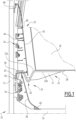
- a vehicle body 10 in particular a railway vehicle car body. More particularly, a side wall 12 of the body 10 and a portion of a floor 14 of the body 10 are shown.
- the wall 12 carries a device 16 for supporting a comfort element 18.
- the comfort element 18 is a seat, but it could alternatively also be chosen from a table and a luggage support.
- the support device 16 comprises a fixing rail 20, fixed to the side wall 12 and extending longitudinally along this side wall 12, that is to say parallel to a longitudinal direction of the car.
- the support device 16 further comprises at least one interface element 22, intended to be fixed to the comfort equipment 18 on the one hand, and to cooperate with the fixing rail 20 on the other hand, for the fixing of this comfort equipment 18 on this fixing rail 20.
- the interface element 22 is for example made of aluminum or steel.
- the support device 16 comprises means (not shown) for fixing the interface element 22 on the fixing rail 20, without which the interface element 22 is movable in translation along the fixing rail 20, and with which the interface element 22 is locked in a chosen position on the fixing rail 20.
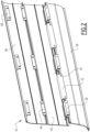
- the fixing means comprise at least one orifice 24 (visible on the figure 2 ) provided on the interface element, and at least one additional clamping screw passing through this orifice 24.
- the interface element 22 has an upper surface 22a and a lower surface 22b, and extends transversely (i.e. parallel to a transverse direction perpendicular to the longitudinal direction) between a first end 26 linked to the fixing rail 20 and a second end 28 fixed to the comfort equipment 18.
- the interface element 22 comprises, between the first 26 and second 28 ends, a central portion 30 in which the upper surface 22a has a hollow and the lower surface 22b has a bump.
- the central portion 30 has a V-shaped cross-section.
- the interface element 22 comprises, on its lower surface 22b, stiffening ribs 31 extending transversely between the central portion 30 and the second end 28. It may also comprise, still on its lower surface 22b, stiffening ribs extending transversely between the central portion 30 and the first end 26.
- the interface element 22 also comprises stiffening ribs extending transversely in the hollow of the central portion 30.
- the comfort element 18 rests on the upper surface 22b, to which it is fixed by any suitable means conceivable.
- the support device 16 further comprises a set 32 of panels, in particular intended to conceal the fixing rail 20, and to conceal cables 34 running along the side wall 12, in particular electric cables and network cables intended to be connected to equipment of the comfort element 18.
- equipment includes for example an electrical outlet, a lamp, a USB port, and/or any possible equipment.
- the assembly 32 comprises a first lower panel 36 comprising a first upper end housed between the hump of the central portion 30 and the side wall 12, and a first lower end fixed to the ground.
- the support device 16 comprises at least one fixing element 38 fixed to the fixing rail 20 in the same way as the interface element 22. More particularly, each interface element 22 is interposed, in the longitudinal direction, between two fixing elements 38, as shown in the figure 2 .
- the fixing element 38 is, in the same way as the interface element 22, movable along the fixing rail 20 as long as it is not locked in a chosen position on this rail 20.
- the first upper end of the first lower panel 36 is fixed to the fixing element 38, for example by fitting together complementary parts, and the first lower end of this first lower panel 36 is fixed to the ground 14 by at least one fixing member, for example by screwing.
- a masking strip 40 is attached to the first lower end, for example by snap-fastening, to mask the at least one fixing member.
- the assembly 32 further comprises a second intermediate panel 42 comprising a second upper end and a second lower end housed in the hollow of the central portion 30.
- the second lower end is also fixed to the fixing element 38, for example by fitting together complementary parts.
- This second lower end covers the first upper end, with sufficient clearance between them to allow the passage of cables.
- the cables 34 can be connected to the comfort equipment by passing through this clearance, and along the interface element 22, to which they can advantageously be fixed.
- the clearance between the second lower end and the first upper end also allows the passage of the interface element 22.
- the second upper end is fixed to an intermediate fixing member 44, itself fixed to the wall 12.
- the assembly 32 finally comprises a third upper panel 46, comprising a third upper end and a third lower end.
- the third lower end covers the second upper end, and it is also fixed to the intermediate fixing member 44.
- the third upper end is fixed to an upper fixing member 48, for example by fitting together complementary parts, the upper fixing member 48 itself being fixed to the side wall 12.
- the intermediate 44 and upper 48 fixing members are for example fixed on rails carried by the side wall 12.
- the support device 16 comprises an end piece at each longitudinal end of the assembly 32, intended to cover the longitudinal end edges of the panels.
- This end piece is for example made of aluminum.
- the panels 36, 42, 46 are for example also made of aluminum, and each have a thickness preferably less than 5 mm, for example 2.5 mm or 3 mm.
- the vehicle is a road vehicle such as a bus or a coach.
Landscapes
- Engineering & Computer Science (AREA)
- Mechanical Engineering (AREA)
- Aviation & Aerospace Engineering (AREA)
- Transportation (AREA)
- Life Sciences & Earth Sciences (AREA)
- Wood Science & Technology (AREA)
- Body Structure For Vehicles (AREA)
Claims (9)
- Halterungsvorrichtung (16) eines Komfortelements (18), das dazu bestimmt ist, in eine Karosserie eines Fahrzeugs installiert zu werden, die Halterungsvorrichtung umfassend:- eine Befestigungsschiene (20), die dazu bestimmt ist, an einer Seitenwand (12) der Karosserie befestigt zu werden, um sich in Längsrichtung entlang dieser Seitenwand (12) zu erstrecken,- mindestens ein Schnittflächenelement (22), das dazu bestimmt ist, an der Komfortausrüstung (18) befestigt zu werden und mit der Befestigungsschiene (20) zusammenzuwirken, für die feste Verbindung dieser Komfortausrüstung (18) mit dieser Befestigungsschiene (20), wobei:- das Schnittflächenelement (22) eine obere Fläche (22a) und eine untere Fläche (22b) aufweist und sich seitlich zwischen einem ersten Ende (26), das mit der Befestigungsschiene (20) verbunden ist, und einem zweiten Ende (28), das an der Komfortausrüstung (18) befestigt ist, erstreckt, wobei das Schnittflächenelement (22) zwischen dem ersten (26) und dem zweiten (28) Ende einen mittleren Abschnitt (30) umfasst, in dem die obere Fläche (22a) eine Vertiefung und die untere Fläche (22b) eine Erhebung aufweist,- die Halterungsvorrichtung (16) eine Anordnung (32) von Platten (36, 42, 46) umfasst, die dazu bestimmt sind, die Befestigungsschiene (20) zu verbergen, die Anordnung umfassend eine erste untere Platte (36), umfassend ein erstes oberes Ende, das geeignet ist, um zwischen der Erhebung des mittleren Abschnitts (30) und dem ersten Ende (26) aufgenommen zu sein, und eine zweite Platte (42), umfassend ein zweites unteres Ende, das geeignet ist, um in der Vertiefung des mittleren Abschnitts (30) aufgenommen zu sein,dadurch gekennzeichnet, dass das Schnittflächenelement (22) Versteifungsrippen umfasst, die ausgewählt sind aus:- Versteifungsrippen (31) auf seiner unteren Oberfläche (22b), die sich quer zwischen dem mittleren Abschnitt (30) und dem zweiten Ende (28) erstrecken,- Versteifungsrippen auf seiner unteren Oberfläche (22b), die sich quer zwischen dem mittleren Abschnitt (30) und dem ersten Ende (26) erstrecken, und/oder- Versteifungsrippen, die sich quer in der Vertiefung des mittleren Abschnitts (30) erstrecken.
- Halterungsvorrichtung (16) nach Anspruch 1, umfassend Befestigungseinrichtungen des Schnittflächenelements (22) an der Befestigungsschiene (20), die geeignet sind, um von einer ersten Konfiguration, in der das Schnittflächenelement (22) translatorisch entlang der Befestigungsschiene (20) beweglich ist, in eine zweiten Konfiguration überzugehen, in der das Schnittflächenelement (22) in einer gewählten Position an der Befestigungsschiene (20) verriegelt ist.
- Halterungsvorrichtung (16) nach Anspruch 2, wobei die Befestigungseinrichtungen mindestens eine Öffnung (24), die an dem Schnittflächenelement (22) ausgebildet ist, und mindestens eine komplementäre Klemmschraube, die durch diese Öffnung (24) verläuft, um mit der Befestigungsschiene (20) zusammenzuwirken, umfassen.
- Halterungsvorrichtung (16) nach einem der vorhergehenden Ansprüche, wobei die erste untere Platte (46) ein erstes unteres Ende, das dazu bestimmt ist, durch mindestens ein Befestigungsorgan an einem Boden (14) der Karosserie befestigt zu sein, und ein Maskierungsband (40) des mindestens einen Befestigungsorgans, das an der ersten unteren Platte (36) angebracht ist, beispielsweise durch Einrasten, umfasst.
- Halterungsvorrichtung (16) nach einem der vorhergehenden Ansprüche, wobei die Anordnung (32) zusätzlich zu der ersten unteren Platte (36) und der zweiten Platte (42) eine dritte obere Platte (46) umfasst, die über der zweiten Platte (42) angeordnet ist.
- Halterungsvorrichtung (16) nach einem der vorhergehenden Ansprüche, umfassend mindestens ein Befestigungselement (38), das an der Befestigungsschiene (20) befestigt ist, wobei das erste obere Ende der ersten unteren Platte (36) an dem Befestigungselement (38) befestigt ist, beispielsweise durch Ineinanderstecken komplementärer Teile, und das zweite untere Ende der zweiten Platte (42) auch an dem Befestigungselement (38) befestigt ist, beispielsweise durch Ineinanderstecken komplementärer Teile.
- Halterungsvorrichtung (16) nach einem der vorherigen Ansprüche, wobei das zweite, untere Ende das erste, obere Ende abdeckt, wobei dazwischen ein ausreichender Abstand besteht, um die Durchführung von Kabeln (34) zu ermöglichen.
- Seitenwand (12) einer Fahrzeugkarosserie, dadurch gekennzeichnet, dass sie eine Halterungsvorrichtung (16) nach einem der vorherigen Ansprüche umfasst.
- Fahrzeug, umfassend mindestens eine Karosserie, die mit zwei Seitenwänden versehen ist, dadurch gekennzeichnet, dass mindestens eine der Seitenwände nach Anspruch 8 ist.
Applications Claiming Priority (1)
| Application Number | Priority Date | Filing Date | Title |
|---|---|---|---|
| FR1871693A FR3088866B1 (fr) | 2018-11-22 | 2018-11-22 | Dispositif de support d’un élément de confort de voiture de véhicule |
Publications (2)
| Publication Number | Publication Date |
|---|---|
| EP3656607A1 EP3656607A1 (de) | 2020-05-27 |
| EP3656607B1 true EP3656607B1 (de) | 2024-10-09 |
Family
ID=65763636
Family Applications (1)
| Application Number | Title | Priority Date | Filing Date |
|---|---|---|---|
| EP19210791.0A Active EP3656607B1 (de) | 2018-11-22 | 2019-11-21 | Halterungsvorrichtung für komfortelement in einem fahrzeug |
Country Status (4)
| Country | Link |
|---|---|
| EP (1) | EP3656607B1 (de) |
| ES (1) | ES3002458T3 (de) |
| FR (1) | FR3088866B1 (de) |
| PL (1) | PL3656607T3 (de) |
Families Citing this family (2)
| Publication number | Priority date | Publication date | Assignee | Title |
|---|---|---|---|---|
| EP4275963B1 (de) * | 2022-05-09 | 2025-07-02 | Ambulanz Mobile GmbH & Co. KG | Kraftfahrzeug-seitenwandkonstruktion, seitenwandelemente für eine kraftfahrzeug-seitenwandkonstruktion sowie montageverfahren |
| FR3141129B1 (fr) * | 2022-10-24 | 2024-11-01 | Speedinnov | Véhicule à plinthes uniques |
Family Cites Families (3)
| Publication number | Priority date | Publication date | Assignee | Title |
|---|---|---|---|---|
| DE19526525C1 (de) * | 1995-07-20 | 1997-02-13 | Daimler Benz Aerospace Airbus | Vorrichtung zum Unterteilen einer Flugzeugkabine |
| FR2920734A1 (fr) * | 2007-09-06 | 2009-03-13 | Alstom Transport Sa | Vehicule comportant une structure multifonctions de support d'equipements |
| FR2979316A1 (fr) * | 2011-08-31 | 2013-03-01 | M Y G | Module prefabrique d'habillage interieur d'au moins une partie d'un habitacle, ensemble forme d'un habitacle et du module precite, et procede d'installation d'un tel module dans un habitacle |
-
2018
- 2018-11-22 FR FR1871693A patent/FR3088866B1/fr active Active
-
2019
- 2019-11-21 PL PL19210791.0T patent/PL3656607T3/pl unknown
- 2019-11-21 EP EP19210791.0A patent/EP3656607B1/de active Active
- 2019-11-21 ES ES19210791T patent/ES3002458T3/es active Active
Also Published As
| Publication number | Publication date |
|---|---|
| PL3656607T3 (pl) | 2025-03-03 |
| ES3002458T3 (en) | 2025-03-07 |
| FR3088866B1 (fr) | 2021-06-25 |
| EP3656607A1 (de) | 2020-05-27 |
| FR3088866A1 (fr) | 2020-05-29 |
Similar Documents
| Publication | Publication Date | Title |
|---|---|---|
| CA2220980C (fr) | Glissiere pour siege de vehicule, et siege equipe d'une telle glissiere | |
| FR2902052A1 (fr) | Siege depliable pour vehicule de transport, et vehicule de transport correspondant | |
| EP3656607B1 (de) | Halterungsvorrichtung für komfortelement in einem fahrzeug | |
| FR2937099A1 (fr) | Systeme de fixation, destine notamment a la fixation de sieges dans un vehicule et plus particulierement dans un aeronef | |
| EP3356168B1 (de) | Flächenbündige verglaste vorrichtung für eine fahrzeugtür mit einer beweglichen platte, sowie entsprechende tür und kraftfahrzeug | |
| EP3865366B1 (de) | Wagen eines öffentlichen transportfahrzeugs, insbesondere eines schienenfahrzeugs, und entsprechendes verfahren zu seiner ausstattung | |
| EP3587212B1 (de) | Terrassenwagen | |
| EP4051590B1 (de) | Stützplatte für flugzeugsitzeinheit | |
| FR2493253A1 (fr) | Structure de toit pour vehicule automobile | |
| FR3066749A1 (fr) | Dispositif de maintien d’une couverture d’insonorisation de traverse inferieure de baie et de tablier avant. | |
| EP3925849B1 (de) | Fahrzeugwaggon, insbesondere eisenbahnwaggon, mit einem dachfenster und entsprechendes montageverfahren | |
| FR3055874A1 (fr) | Voiture de restauration modulable, notamment pour un vehicule ferroviaire | |
| FR2996182A1 (fr) | Glissiere et siege de vehicule automobile comportant une telle glissiere | |
| EP2572962B1 (de) | Befestigungseinheit für Lenksäule | |
| FR3135936A1 (fr) | Support de boîtier électronique pour vehicules automobiles | |
| EP4360982B1 (de) | Fahrzeug mit einzelnen sockelleisten | |
| EP3828026A1 (de) | Befestigungsvorrichtung für fahrzeugsitz | |
| FR2779581A1 (fr) | Enveloppe devant loger des appareillages electriques | |
| EP4244978B1 (de) | Verbesserte trägerplatte für fotovoltaische tafeln | |
| EP4039538B1 (de) | Komfortausstattung für ein öffentliches transportfahrzeug, die einen freitragenden tisch umfasst | |
| FR3141425A1 (fr) | Boitier d’intercirculation pour extrémité de voiture de véhicule ferroviaire et procédé d’assemblage associé | |
| EP4091873A1 (de) | Sitz für ein passagiertransportfahrzeug und passagiertransportfahrzeug mit einem solchen sitz | |
| FR3103453A1 (fr) | Montage de garnitures sur un longeron de véhicule automobile | |
| EP3254903B1 (de) | Fixierteil für verkleidungselemente auf einer seitlichen struktur eines kraftfahrzeugs | |
| FR3111653A1 (fr) | Dispositif pour la formation d’une balustrade dans un véhicule, notamment ferroviaire |
Legal Events
| Date | Code | Title | Description |
|---|---|---|---|
| PUAI | Public reference made under article 153(3) epc to a published international application that has entered the european phase |
Free format text: ORIGINAL CODE: 0009012 |
|
| STAA | Information on the status of an ep patent application or granted ep patent |
Free format text: STATUS: THE APPLICATION HAS BEEN PUBLISHED |
|
| STAA | Information on the status of an ep patent application or granted ep patent |
Free format text: STATUS: REQUEST FOR EXAMINATION WAS MADE |
|
| AK | Designated contracting states |
Kind code of ref document: A1 Designated state(s): AL AT BE BG CH CY CZ DE DK EE ES FI FR GB GR HR HU IE IS IT LI LT LU LV MC MK MT NL NO PL PT RO RS SE SI SK SM TR |
|
| AX | Request for extension of the european patent |
Extension state: BA ME |
|
| 17P | Request for examination filed |
Effective date: 20200519 |
|
| RBV | Designated contracting states (corrected) |
Designated state(s): AL AT BE BG CH CY CZ DE DK EE ES FI FR GB GR HR HU IE IS IT LI LT LU LV MC MK MT NL NO PL PT RO RS SE SI SK SM TR |
|
| STAA | Information on the status of an ep patent application or granted ep patent |
Free format text: STATUS: EXAMINATION IS IN PROGRESS |
|
| 17Q | First examination report despatched |
Effective date: 20210920 |
|
| P01 | Opt-out of the competence of the unified patent court (upc) registered |
Effective date: 20231026 |
|
| GRAP | Despatch of communication of intention to grant a patent |
Free format text: ORIGINAL CODE: EPIDOSNIGR1 |
|
| STAA | Information on the status of an ep patent application or granted ep patent |
Free format text: STATUS: GRANT OF PATENT IS INTENDED |
|
| INTG | Intention to grant announced |
Effective date: 20240507 |
|
| RIN1 | Information on inventor provided before grant (corrected) |
Inventor name: NOE, LUDOVIC Inventor name: HUART, JOHAN Inventor name: BOULAY, ADRIEN Inventor name: RODRIGUEZ-GOMEZ, MARIA-ISABEL |
|
| GRAS | Grant fee paid |
Free format text: ORIGINAL CODE: EPIDOSNIGR3 |
|
| GRAA | (expected) grant |
Free format text: ORIGINAL CODE: 0009210 |
|
| STAA | Information on the status of an ep patent application or granted ep patent |
Free format text: STATUS: THE PATENT HAS BEEN GRANTED |
|
| AK | Designated contracting states |
Kind code of ref document: B1 Designated state(s): AL AT BE BG CH CY CZ DE DK EE ES FI FR GB GR HR HU IE IS IT LI LT LU LV MC MK MT NL NO PL PT RO RS SE SI SK SM TR |
|
| REG | Reference to a national code |
Ref country code: CH Ref legal event code: EP |
|
| REG | Reference to a national code |
Ref country code: DE Ref legal event code: R096 Ref document number: 602019059974 Country of ref document: DE |
|
| REG | Reference to a national code |
Ref country code: IE Ref legal event code: FG4D Free format text: LANGUAGE OF EP DOCUMENT: FRENCH |
|
| REG | Reference to a national code |
Ref country code: LT Ref legal event code: MG9D |
|
| REG | Reference to a national code |
Ref country code: NL Ref legal event code: MP Effective date: 20241009 |
|
| REG | Reference to a national code |
Ref country code: ES Ref legal event code: FG2A Ref document number: 3002458 Country of ref document: ES Kind code of ref document: T3 Effective date: 20250307 |
|
| REG | Reference to a national code |
Ref country code: AT Ref legal event code: MK05 Ref document number: 1730251 Country of ref document: AT Kind code of ref document: T Effective date: 20241009 |
|
| PG25 | Lapsed in a contracting state [announced via postgrant information from national office to epo] |
Ref country code: NL Free format text: LAPSE BECAUSE OF FAILURE TO SUBMIT A TRANSLATION OF THE DESCRIPTION OR TO PAY THE FEE WITHIN THE PRESCRIBED TIME-LIMIT Effective date: 20241009 |
|
| PG25 | Lapsed in a contracting state [announced via postgrant information from national office to epo] |
Ref country code: NL Free format text: LAPSE BECAUSE OF FAILURE TO SUBMIT A TRANSLATION OF THE DESCRIPTION OR TO PAY THE FEE WITHIN THE PRESCRIBED TIME-LIMIT Effective date: 20241009 |
|
| PG25 | Lapsed in a contracting state [announced via postgrant information from national office to epo] |
Ref country code: HR Free format text: LAPSE BECAUSE OF FAILURE TO SUBMIT A TRANSLATION OF THE DESCRIPTION OR TO PAY THE FEE WITHIN THE PRESCRIBED TIME-LIMIT Effective date: 20241009 Ref country code: PT Free format text: LAPSE BECAUSE OF FAILURE TO SUBMIT A TRANSLATION OF THE DESCRIPTION OR TO PAY THE FEE WITHIN THE PRESCRIBED TIME-LIMIT Effective date: 20250210 Ref country code: IS Free format text: LAPSE BECAUSE OF FAILURE TO SUBMIT A TRANSLATION OF THE DESCRIPTION OR TO PAY THE FEE WITHIN THE PRESCRIBED TIME-LIMIT Effective date: 20250209 |
|
| PG25 | Lapsed in a contracting state [announced via postgrant information from national office to epo] |
Ref country code: FI Free format text: LAPSE BECAUSE OF FAILURE TO SUBMIT A TRANSLATION OF THE DESCRIPTION OR TO PAY THE FEE WITHIN THE PRESCRIBED TIME-LIMIT Effective date: 20241009 |
|
| PG25 | Lapsed in a contracting state [announced via postgrant information from national office to epo] |
Ref country code: BG Free format text: LAPSE BECAUSE OF FAILURE TO SUBMIT A TRANSLATION OF THE DESCRIPTION OR TO PAY THE FEE WITHIN THE PRESCRIBED TIME-LIMIT Effective date: 20241009 |
|
| PG25 | Lapsed in a contracting state [announced via postgrant information from national office to epo] |
Ref country code: NO Free format text: LAPSE BECAUSE OF FAILURE TO SUBMIT A TRANSLATION OF THE DESCRIPTION OR TO PAY THE FEE WITHIN THE PRESCRIBED TIME-LIMIT Effective date: 20250109 |
|
| PG25 | Lapsed in a contracting state [announced via postgrant information from national office to epo] |
Ref country code: GR Free format text: LAPSE BECAUSE OF FAILURE TO SUBMIT A TRANSLATION OF THE DESCRIPTION OR TO PAY THE FEE WITHIN THE PRESCRIBED TIME-LIMIT Effective date: 20250110 Ref country code: LV Free format text: LAPSE BECAUSE OF FAILURE TO SUBMIT A TRANSLATION OF THE DESCRIPTION OR TO PAY THE FEE WITHIN THE PRESCRIBED TIME-LIMIT Effective date: 20241009 Ref country code: AT Free format text: LAPSE BECAUSE OF FAILURE TO SUBMIT A TRANSLATION OF THE DESCRIPTION OR TO PAY THE FEE WITHIN THE PRESCRIBED TIME-LIMIT Effective date: 20241009 |
|
| PG25 | Lapsed in a contracting state [announced via postgrant information from national office to epo] |
Ref country code: RS Free format text: LAPSE BECAUSE OF FAILURE TO SUBMIT A TRANSLATION OF THE DESCRIPTION OR TO PAY THE FEE WITHIN THE PRESCRIBED TIME-LIMIT Effective date: 20250109 |
|
| PG25 | Lapsed in a contracting state [announced via postgrant information from national office to epo] |
Ref country code: SM Free format text: LAPSE BECAUSE OF FAILURE TO SUBMIT A TRANSLATION OF THE DESCRIPTION OR TO PAY THE FEE WITHIN THE PRESCRIBED TIME-LIMIT Effective date: 20241009 |
|
| PG25 | Lapsed in a contracting state [announced via postgrant information from national office to epo] |
Ref country code: MC Free format text: LAPSE BECAUSE OF FAILURE TO SUBMIT A TRANSLATION OF THE DESCRIPTION OR TO PAY THE FEE WITHIN THE PRESCRIBED TIME-LIMIT Effective date: 20241009 |
|
| PG25 | Lapsed in a contracting state [announced via postgrant information from national office to epo] |
Ref country code: DK Free format text: LAPSE BECAUSE OF FAILURE TO SUBMIT A TRANSLATION OF THE DESCRIPTION OR TO PAY THE FEE WITHIN THE PRESCRIBED TIME-LIMIT Effective date: 20241009 |
|
| REG | Reference to a national code |
Ref country code: DE Ref legal event code: R097 Ref document number: 602019059974 Country of ref document: DE |
|
| PG25 | Lapsed in a contracting state [announced via postgrant information from national office to epo] |
Ref country code: LU Free format text: LAPSE BECAUSE OF NON-PAYMENT OF DUE FEES Effective date: 20241121 |
|
| PG25 | Lapsed in a contracting state [announced via postgrant information from national office to epo] |
Ref country code: EE Free format text: LAPSE BECAUSE OF FAILURE TO SUBMIT A TRANSLATION OF THE DESCRIPTION OR TO PAY THE FEE WITHIN THE PRESCRIBED TIME-LIMIT Effective date: 20241009 |
|
| PG25 | Lapsed in a contracting state [announced via postgrant information from national office to epo] |
Ref country code: RO Free format text: LAPSE BECAUSE OF FAILURE TO SUBMIT A TRANSLATION OF THE DESCRIPTION OR TO PAY THE FEE WITHIN THE PRESCRIBED TIME-LIMIT Effective date: 20241009 |
|
| PG25 | Lapsed in a contracting state [announced via postgrant information from national office to epo] |
Ref country code: SK Free format text: LAPSE BECAUSE OF FAILURE TO SUBMIT A TRANSLATION OF THE DESCRIPTION OR TO PAY THE FEE WITHIN THE PRESCRIBED TIME-LIMIT Effective date: 20241009 |
|
| PG25 | Lapsed in a contracting state [announced via postgrant information from national office to epo] |
Ref country code: CZ Free format text: LAPSE BECAUSE OF FAILURE TO SUBMIT A TRANSLATION OF THE DESCRIPTION OR TO PAY THE FEE WITHIN THE PRESCRIBED TIME-LIMIT Effective date: 20241009 |
|
| PLBE | No opposition filed within time limit |
Free format text: ORIGINAL CODE: 0009261 |
|
| STAA | Information on the status of an ep patent application or granted ep patent |
Free format text: STATUS: NO OPPOSITION FILED WITHIN TIME LIMIT |
|
| REG | Reference to a national code |
Ref country code: BE Ref legal event code: MM Effective date: 20241130 |
|
| PG25 | Lapsed in a contracting state [announced via postgrant information from national office to epo] |
Ref country code: SE Free format text: LAPSE BECAUSE OF FAILURE TO SUBMIT A TRANSLATION OF THE DESCRIPTION OR TO PAY THE FEE WITHIN THE PRESCRIBED TIME-LIMIT Effective date: 20241009 |
|
| 26N | No opposition filed |
Effective date: 20250710 |
|
| PG25 | Lapsed in a contracting state [announced via postgrant information from national office to epo] |
Ref country code: BE Free format text: LAPSE BECAUSE OF NON-PAYMENT OF DUE FEES Effective date: 20241130 |
|
| PG25 | Lapsed in a contracting state [announced via postgrant information from national office to epo] |
Ref country code: IE Free format text: LAPSE BECAUSE OF NON-PAYMENT OF DUE FEES Effective date: 20241121 |
|
| REG | Reference to a national code |
Ref country code: CH Ref legal event code: U11 Free format text: ST27 STATUS EVENT CODE: U-0-0-U10-U11 (AS PROVIDED BY THE NATIONAL OFFICE) Effective date: 20251201 |
|
| PGFP | Annual fee paid to national office [announced via postgrant information from national office to epo] |
Ref country code: DE Payment date: 20251119 Year of fee payment: 7 |
|
| PGFP | Annual fee paid to national office [announced via postgrant information from national office to epo] |
Ref country code: GB Payment date: 20251121 Year of fee payment: 7 |
|
| PGFP | Annual fee paid to national office [announced via postgrant information from national office to epo] |
Ref country code: IT Payment date: 20251125 Year of fee payment: 7 |
|
| PGFP | Annual fee paid to national office [announced via postgrant information from national office to epo] |
Ref country code: FR Payment date: 20251126 Year of fee payment: 7 |
|
| PGFP | Annual fee paid to national office [announced via postgrant information from national office to epo] |
Ref country code: CH Payment date: 20251201 Year of fee payment: 7 |
|
| PGFP | Annual fee paid to national office [announced via postgrant information from national office to epo] |
Ref country code: PL Payment date: 20251114 Year of fee payment: 7 |
|
| PGFP | Annual fee paid to national office [announced via postgrant information from national office to epo] |
Ref country code: ES Payment date: 20251229 Year of fee payment: 7 |
|
| PG25 | Lapsed in a contracting state [announced via postgrant information from national office to epo] |
Ref country code: HU Free format text: LAPSE BECAUSE OF FAILURE TO SUBMIT A TRANSLATION OF THE DESCRIPTION OR TO PAY THE FEE WITHIN THE PRESCRIBED TIME-LIMIT; INVALID AB INITIO Effective date: 20191121 |
|
| PG25 | Lapsed in a contracting state [announced via postgrant information from national office to epo] |
Ref country code: CY Free format text: LAPSE BECAUSE OF FAILURE TO SUBMIT A TRANSLATION OF THE DESCRIPTION OR TO PAY THE FEE WITHIN THE PRESCRIBED TIME-LIMIT; INVALID AB INITIO Effective date: 20191121 |