EP3656963B1 - Dispositif de raccourcissement des lames d'une store à lames et méthode de raccourcissement des lames - Google Patents
Dispositif de raccourcissement des lames d'une store à lames et méthode de raccourcissement des lames Download PDFInfo
- Publication number
- EP3656963B1 EP3656963B1 EP19178031.1A EP19178031A EP3656963B1 EP 3656963 B1 EP3656963 B1 EP 3656963B1 EP 19178031 A EP19178031 A EP 19178031A EP 3656963 B1 EP3656963 B1 EP 3656963B1
- Authority
- EP
- European Patent Office
- Prior art keywords
- clamping
- clamping plates
- slats
- blind
- plates
- Prior art date
- Legal status (The legal status is an assumption and is not a legal conclusion. Google has not performed a legal analysis and makes no representation as to the accuracy of the status listed.)
- Active
Links
Images
Classifications
-
- E—FIXED CONSTRUCTIONS
- E06—DOORS, WINDOWS, SHUTTERS, OR ROLLER BLINDS IN GENERAL; LADDERS
- E06B—FIXED OR MOVABLE CLOSURES FOR OPENINGS IN BUILDINGS, VEHICLES, FENCES OR LIKE ENCLOSURES IN GENERAL, e.g. DOORS, WINDOWS, BLINDS, GATES
- E06B9/00—Screening or protective devices for wall or similar openings, with or without operating or securing mechanisms; Closures of similar construction
- E06B9/24—Screens or other constructions affording protection against light, especially against sunshine; Similar screens for privacy or appearance; Slat blinds
- E06B9/26—Lamellar or like blinds, e.g. venetian blinds
- E06B9/266—Devices or accessories for making or mounting lamellar blinds or parts thereof
-
- B—PERFORMING OPERATIONS; TRANSPORTING
- B23—MACHINE TOOLS; METAL-WORKING NOT OTHERWISE PROVIDED FOR
- B23D—PLANING; SLOTTING; SHEARING; BROACHING; SAWING; FILING; SCRAPING; LIKE OPERATIONS FOR WORKING METAL BY REMOVING MATERIAL, NOT OTHERWISE PROVIDED FOR
- B23D23/00—Machines or devices for shearing or cutting profiled stock
-
- B—PERFORMING OPERATIONS; TRANSPORTING
- B23—MACHINE TOOLS; METAL-WORKING NOT OTHERWISE PROVIDED FOR
- B23D—PLANING; SLOTTING; SHEARING; BROACHING; SAWING; FILING; SCRAPING; LIKE OPERATIONS FOR WORKING METAL BY REMOVING MATERIAL, NOT OTHERWISE PROVIDED FOR
- B23D23/00—Machines or devices for shearing or cutting profiled stock
- B23D2023/005—Machines or devices for shearing or cutting profiled stock for window coverings
Definitions
- blinds have to be shortened in their width by shortening the slats of the blind, for example in the case of measurement errors when measuring the blind.
- the blind has to be dismantled to do this, in order to then shorten each slat accordingly. This is associated with considerable effort. It is also easy to make mistakes when shortening the slats.
- DE9419590 U1 discloses an apparatus for clamping slats of a blind for shortening those slats relative to the width of the blind.
- the object of the invention is to provide an improved device for clamping slats of a blind in order to shorten them. According to the invention, this is achieved by a device having the features of claim 1.
- a device according to the invention preferably comprises more than 10
- the clamping plates advantageously comprise a lower end clamping plate which has an upper clamping contour on its upper side, an upper end clamping plate which has a lower clamping contour on its underside and a plurality of middle clamping plates which have upper and lower clamping contours on their upper and lower sides ,
- the clamping slots are each formed by the upper clamping contour of one of the clamping plates and the lower clamping contour of the adjacent overlying clamping plate.
- the lower end clamping plate and the upper end clamping plate can advantageously be designed to interact with a clamping device for clamping the stack of clamping plates with the lamellae inserted between them.
- the top of the top end clip may be flat, as may the bottom of the bottom end clip.
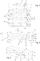
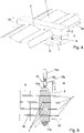
- FIG. 1-5 An embodiment of a device according to the invention is in the Figures 1-5 shown (where the sectional view of figure 5 is schematized).
- the device includes several clamping plates 1-3.
- the clamping plates 1-3 can be stacked together as shown in 3 is shown for three clamping plates.
- a bottom end clip 1 is located at the very bottom of the stack.
- a top end clip 3 is placed at the top of the stack.
- a plurality of central clamping plates 2 are arranged (wherein 3 for the sake of simplicity, only one of these middle clamping plates 2 is shown).
- the adjacent clamping plates 1-3 in the stack each have a clamping contour 4, 5 on their mutually facing surfaces.
- the clamping contours 4, 5 each form a clamping slot 6 for receiving one of the slats 7 of the blind 8 between two adjacent clamping plates 1-3.
- the clamping slot 6 is adapted to the contour of the lamella 7 .
- the width of the clamping slot 6 is slightly smaller than the thickness of the slat 7.
- the middle clamping plates 2 each have an upper and a lower clamping contour 4 , 5 .
- the upper clamping contours 4 of all middle clamping plates 2 are of the same design, as are the lower clamping contours 5 of all middle ones Clamping plates 2 designed the same.
- the middle clamping plates 2 are all of the same design, as is preferred.
- the lower end clamping plate 1 has only one upper clamping contour 4 on its upper side, which has the same design as the upper clamping contours 4 of the middle clamping plate 2.
- the lower end clamping plate is flat on the underside, which means that the clamping of the a stack arranged clamping plates 1-3 is facilitated.
- the upper end clamping plate 3 has only a lower clamping contour 5 on its underside. This is designed in the same way as the lower clamping contours 5 of the middle clamping plates 2 .
- the upper end clamping plate 3 is flat on its upper side, which makes it easier to clamp the clamping plates 1-3 assembled into a stack.
- centering elements 9, 10 are aligned by centering elements 9, 10 in their mutual position to one another.
- these centering elements 9, 10 are formed by nub-like projections (centering elements 9) and corresponding depressions (centering elements 10).
- the depressions forming the centering elements 10 are only in 2 indicated by dashed lines.
- centering elements 9 in the form of nub-like elevations can be arranged on the upper sides of the middle clamping plates 2 and on the upper side of the lower end clamping plate 1, and the centering elements 10 in the form of corresponding depressions can be arranged on the undersides of the middle clamping plates 2 and on the underside of the upper end clamping plate 3 may be arranged.
- the clamping plates 1-3 assembled into a stack can be clamped together with a clamping device 13 .
- the clamping device 13 With the clamping device 13, the clamping plates 1-3 can thus be clamped together in relation to the stacking direction 12.
- the clamping device is only in figure 5 implied.
- it can be a conventional screw clamp. This has a fixed clamping arm 13a and a movable clamping arm 13b on a rail (not shown), which has a threaded bore through which a spindle 13c with a handle 13d and a pressure plate 13e extends.
- Clamping devices designed in a different way can also be used.
- a number of consecutive slats 7 of the blind for example 15 slats, are inserted into the clamping slots 6.
- the clamping plates 1-3 can be assembled one after the other, with clamping plates 1-3 being able to be used individually between successive slats 7 of the blind 8 in a simple manner.
- the slats 7 can remain connected to one another.
- a strip 14 connecting the slats 7 is shown schematically.
- the assembled clamping plates 1-3 are in this case aligned by the centering elements 9, 10 to one another.
- the separation of the laminations 7 in the region of their edge sections is advantageously carried out close to the stack of the clamped small plates 1-3, preferably at a distance of less than 5 mm.
- centering elements 9, 10 can be used, for example also pin-like.
- the centering elements 9, 10 then prevent a mutual displacement of the clamping plates 1-3 assembled into a stack in the direction parallel to the direction of the longitudinal extent 11 of the slats 7.
- Such centering elements could be designed, for example, in the form of strips which engage in grooves.
- clamping plates 1-3 in relation to a direction parallel to the direction of the longitudinal extent 11 of the clamping plates 1-3 could then be effected solely by the clamping contours 4, 5 in conjunction with the slats 7 arranged in the clamping slots 6.
Landscapes
- Engineering & Computer Science (AREA)
- Structural Engineering (AREA)
- Mechanical Engineering (AREA)
- Architecture (AREA)
- Civil Engineering (AREA)
- Jigs For Machine Tools (AREA)
- Blinds (AREA)
Claims (9)
- Dispositif pour serrer des lamelles (7) d'un store vénitien (8) pour raccourcir ces lamelles (7) du point de vue de la largeur du store vénitien, caractérisé par plusieurs plaquettes de serrage (1-3) qui peuvent être assemblées en une pile, des plaquettes de serrage (1-3) successives dans la pile étant alignées les unes par rapport aux autres par des éléments de centrage (9, 10) des plaquettes de serrage (1-3) au moins par rapport à une direction parallèle à la direction (16) de l'extension longitudinale des lamelles (7) à serrer, et une fente de serrage (6) étant présente à chaque fois entre des plaquettes de serrage (1-3) successives de la pile pour serrer l'une des lamelles (7) du store vénitien (8), des protubérances orientées vers le haut et/ou vers le bas étant présentes sur au moins l'une des plaquettes de serrage (1-3) successives en tant qu'éléments de centrage (9, 10) pour l'alignement mutuel de plaquettes de serrage (1-3) adjacentes, lesquelles protubérances s'engageant chacune dans un renfoncement dans l'autre des plaquettes de serrage adjacentes.
- Dispositif selon la revendication 1, caractérisé en ce que les plaquettes de serrage (1-3) assemblées en une pile peuvent être serrées les unes contre les autres au moyen d'un dispositif de serrage (13).
- Dispositif selon la revendication 2, caractérisé en ce que le dispositif de serrage (13) est un serre-joint.
- Dispositif selon l'une des revendications 1 à 3, caractérisé en ce que les plaquettes de serrage (1-3) comprennent une plaquette de serrage d'extrémité inférieure (1) présentant un contour de serrage supérieur (4) sur sa face supérieure, une plaquette de serrage d'extrémité supérieure (3) présentant un contour de serrage inférieur (5) sur sa face inférieure, et plusieurs plaquettes de serrage centrales (2) présentant sur leurs faces supérieure et inférieure des contours de serrage supérieurs et inférieurs (4, 5), les fentes de serrage (6) étant formées respectivement par le contour de serrage supérieur (4) de l'une des plaquettes de serrage (1, 2) et par le contour de serrage inférieur (5) de la plaquette de serrage (2, 3) adjacente située au-dessus.
- Dispositif selon la revendication 4, caractérisé en ce que la face inférieure de la plaquette de serrage d'extrémité inférieure (1) et/ou la face supérieure de la plaquette de serrage d'extrémité supérieure (3) sont planes.
- Dispositif selon la revendication 4 ou 5, caractérisé en ce que les plaquettes de serrage centrales (2) sont toutes identiques.
- Dispositif selon l'une des revendications 1 à 6, caractérisé en ce que les éléments de centrage (9) formés par les protubérances sont en forme de picots ou de tenons.
- Dispositif selon l'une des revendications 1 à 7, caractérisé en ce que le dispositif comporte plus de 10 plaquettes de serrage (1-3).
- Procédé pour raccourcir des lamelles (7) d'un store vénitien (8) au moyen d'un dispositif selon l'une des revendications 1 à 8, caractérisé en ce qu'au moins plusieurs lamelles (7) successives du store vénitien (8) sont insérées dans les fentes de serrage (6) entre respectivement deux plaquettes de serrage (1-3) adjacentes, ce qui forme la pile de plaquettes de serrage (1-3) de laquelle dépassent d'un côté des sections de bord des lamelles (7) à raccourcir, en ce que les plaquettes de serrage (1-3) sont serrées ensemble au moyen d'un dispositif de serrage (13) avec les lamelles (7) situées entre elles, et en ce que des sections de bord des lamelles (7) dépassant des fentes de serrage (6) sont raccourcies au moyen d'un outil de coupe (15).
Applications Claiming Priority (1)
| Application Number | Priority Date | Filing Date | Title |
|---|---|---|---|
| ATA349/2018A AT521024B1 (de) | 2018-11-20 | 2018-11-20 | Vorrichtung zum Kürzen von Lamellen einer Jalousie |
Publications (2)
| Publication Number | Publication Date |
|---|---|
| EP3656963A1 EP3656963A1 (fr) | 2020-05-27 |
| EP3656963B1 true EP3656963B1 (fr) | 2022-09-14 |
Family
ID=66751957
Family Applications (1)
| Application Number | Title | Priority Date | Filing Date |
|---|---|---|---|
| EP19178031.1A Active EP3656963B1 (fr) | 2018-11-20 | 2019-06-04 | Dispositif de raccourcissement des lames d'une store à lames et méthode de raccourcissement des lames |
Country Status (2)
| Country | Link |
|---|---|
| EP (1) | EP3656963B1 (fr) |
| AT (1) | AT521024B1 (fr) |
Citations (1)
| Publication number | Priority date | Publication date | Assignee | Title |
|---|---|---|---|---|
| US5927172A (en) * | 1998-01-21 | 1999-07-27 | Wang; Cherng-Fa | Venetian blind cutting machine |
Family Cites Families (5)
| Publication number | Priority date | Publication date | Assignee | Title |
|---|---|---|---|---|
| US4525907A (en) * | 1983-08-01 | 1985-07-02 | Tachikawa Blind Kogyo Kabushiki Kaisha | Device for assembling blinds |
| DE9004940U1 (de) * | 1990-05-01 | 1991-08-29 | Kuppinger, Ursula, 6823 Neulußheim | Vorrichtung zum Ablängen und Lochstanzen von Profilschienen |
| DE9419590U1 (de) * | 1994-12-07 | 1995-02-02 | Teh Yor Industrial Co. Ltd., Taipeh/T'ai-Pei | Schneideinrichtung für Jalousien |
| US6108891A (en) * | 1998-03-03 | 2000-08-29 | Newell Operating Company | Soft vertical packaging/installation apparatus |
| ES2246873T3 (es) * | 1999-07-23 | 2006-03-01 | Shade-O-Matic Limited | Maquina de retestar persianas con sierra giratoria. |
-
2018
- 2018-11-20 AT ATA349/2018A patent/AT521024B1/de not_active IP Right Cessation
-
2019
- 2019-06-04 EP EP19178031.1A patent/EP3656963B1/fr active Active
Patent Citations (1)
| Publication number | Priority date | Publication date | Assignee | Title |
|---|---|---|---|---|
| US5927172A (en) * | 1998-01-21 | 1999-07-27 | Wang; Cherng-Fa | Venetian blind cutting machine |
Also Published As
| Publication number | Publication date |
|---|---|
| EP3656963A1 (fr) | 2020-05-27 |
| AT521024A4 (de) | 2019-10-15 |
| AT521024B1 (de) | 2019-10-15 |
Similar Documents
| Publication | Publication Date | Title |
|---|---|---|
| DE3638905A1 (de) | Verfahren und vorrichtung zur gleichzeitigen fertigung einer mehrzahl von jalousien | |
| DE2928459A1 (de) | Bauverbindung | |
| DE2848554A1 (de) | Stanzmesser | |
| DE3430496C2 (de) | Hilfsvorrichtung zum Fräsen von Schwalbenschwanznuten bei rechtwinklig zusammenzuzinkenden Brettern | |
| DE2319374A1 (de) | Nagel sowie verfahren und vorrichtung zu dessen herstellung | |
| DE3018985A1 (de) | Verfahren und vorrichtung zum zersaegen von baumstaemmen in quaderfoermige zuschnitte | |
| EP3656963B1 (fr) | Dispositif de raccourcissement des lames d'une store à lames et méthode de raccourcissement des lames | |
| EP3045278A1 (fr) | Procede de fabrication de planches et/ou de blocs en bois | |
| WO2016097426A1 (fr) | Dispositif et procédé de fabrication d'un élément profilé allongé | |
| DE3120961C2 (de) | Kreissägemaschine | |
| AT507591B1 (de) | Verfahren zum zersägen zumindest einer platte | |
| DE20013789U1 (de) | Schnellspannvorrichtung für das Sägeblatt einer elektrischen Säbelsäge | |
| EP0399346A1 (fr) | Procédé de fabrication de panneaux isolants pour toits inclinés, et dispositif de tranchage pour l'exécution du procédé | |
| DE3204032C2 (fr) | ||
| DE3343787A1 (de) | Schweissraupenverputzmaschine mit verstellbaren anschlaegen fuer fensterrahmen od. dgl. aus kunststoff | |
| DE533646C (de) | Vorrichtung zum gleichzeitigen Einspannen einer Mehrzahl von stabfoermigen Werkstuecken mit mindestens drei in der Laengsrichtung des Werkstueckes gegeneinander versetzten Spannbacken | |
| DE1777184C3 (de) | Blechschneideeinrichtung | |
| DE69100898T2 (de) | Stanzstempelhalteblock und montageverfahren der stempel im genannten block. | |
| DE102014007829A1 (de) | Verfahren und Vorrichtung zum Erstellen einer ebenen Fläche | |
| AT409467B (de) | Vorrichtung bei nuten zur aufnahme eines unteren klemmbackens von einschubaggregaten bei unterflursägemaschinen | |
| DE1427752C (de) | Verfahren zum Planfräsen der Seitenflächen von Blöcken oder Platten aus gehärtetem Leichtbeton oder anderem spröden Material | |
| DE854116C (de) | Locheinrichtung | |
| DE9306314U1 (de) | Vorrichtung zum Zertrennen von Gitterrosten | |
| AT411889B (de) | Einrichtung zum zerteilen von rundholz | |
| AT257994B (de) | Verfahren zur Herstellung von Matrizenelementen zum Durchlochen von Lochkarten |
Legal Events
| Date | Code | Title | Description |
|---|---|---|---|
| PUAI | Public reference made under article 153(3) epc to a published international application that has entered the european phase |
Free format text: ORIGINAL CODE: 0009012 |
|
| STAA | Information on the status of an ep patent application or granted ep patent |
Free format text: STATUS: THE APPLICATION HAS BEEN PUBLISHED |
|
| AK | Designated contracting states |
Kind code of ref document: A1 Designated state(s): AL AT BE BG CH CY CZ DE DK EE ES FI FR GB GR HR HU IE IS IT LI LT LU LV MC MK MT NL NO PL PT RO RS SE SI SK SM TR |
|
| AX | Request for extension of the european patent |
Extension state: BA ME |
|
| STAA | Information on the status of an ep patent application or granted ep patent |
Free format text: STATUS: REQUEST FOR EXAMINATION WAS MADE |
|
| RBV | Designated contracting states (corrected) |
Designated state(s): AL AT BE BG CH CY CZ DE DK EE ES FI FR GB GR HR HU IE IS IT LI LT LU LV MC MK MT NL NO PL PT RO RS SE SI SK SM TR |
|
| 17P | Request for examination filed |
Effective date: 20200610 |
|
| RAP1 | Party data changed (applicant data changed or rights of an application transferred) |
Owner name: GRUBER, MANFRED |
|
| RIN1 | Information on inventor provided before grant (corrected) |
Inventor name: GRUBER, MANFRED |
|
| STAA | Information on the status of an ep patent application or granted ep patent |
Free format text: STATUS: EXAMINATION IS IN PROGRESS |
|
| 17Q | First examination report despatched |
Effective date: 20211025 |
|
| GRAP | Despatch of communication of intention to grant a patent |
Free format text: ORIGINAL CODE: EPIDOSNIGR1 |
|
| STAA | Information on the status of an ep patent application or granted ep patent |
Free format text: STATUS: GRANT OF PATENT IS INTENDED |
|
| INTG | Intention to grant announced |
Effective date: 20220502 |
|
| GRAS | Grant fee paid |
Free format text: ORIGINAL CODE: EPIDOSNIGR3 |
|
| GRAA | (expected) grant |
Free format text: ORIGINAL CODE: 0009210 |
|
| STAA | Information on the status of an ep patent application or granted ep patent |
Free format text: STATUS: THE PATENT HAS BEEN GRANTED |
|
| AK | Designated contracting states |
Kind code of ref document: B1 Designated state(s): AL AT BE BG CH CY CZ DE DK EE ES FI FR GB GR HR HU IE IS IT LI LT LU LV MC MK MT NL NO PL PT RO RS SE SI SK SM TR |
|
| REG | Reference to a national code |
Ref country code: GB Ref legal event code: FG4D Free format text: NOT ENGLISH |
|
| REG | Reference to a national code |
Ref country code: CH Ref legal event code: EP |
|
| REG | Reference to a national code |
Ref country code: DE Ref legal event code: R096 Ref document number: 502019005646 Country of ref document: DE |
|
| REG | Reference to a national code |
Ref country code: IE Ref legal event code: FG4D Free format text: LANGUAGE OF EP DOCUMENT: GERMAN |
|
| REG | Reference to a national code |
Ref country code: AT Ref legal event code: REF Ref document number: 1518800 Country of ref document: AT Kind code of ref document: T Effective date: 20221015 |
|
| REG | Reference to a national code |
Ref country code: LT Ref legal event code: MG9D |
|
| REG | Reference to a national code |
Ref country code: NL Ref legal event code: MP Effective date: 20220914 |
|
| PG25 | Lapsed in a contracting state [announced via postgrant information from national office to epo] |
Ref country code: SE Free format text: LAPSE BECAUSE OF FAILURE TO SUBMIT A TRANSLATION OF THE DESCRIPTION OR TO PAY THE FEE WITHIN THE PRESCRIBED TIME-LIMIT Effective date: 20220914 Ref country code: RS Free format text: LAPSE BECAUSE OF FAILURE TO SUBMIT A TRANSLATION OF THE DESCRIPTION OR TO PAY THE FEE WITHIN THE PRESCRIBED TIME-LIMIT Effective date: 20220914 Ref country code: NO Free format text: LAPSE BECAUSE OF FAILURE TO SUBMIT A TRANSLATION OF THE DESCRIPTION OR TO PAY THE FEE WITHIN THE PRESCRIBED TIME-LIMIT Effective date: 20221214 Ref country code: LV Free format text: LAPSE BECAUSE OF FAILURE TO SUBMIT A TRANSLATION OF THE DESCRIPTION OR TO PAY THE FEE WITHIN THE PRESCRIBED TIME-LIMIT Effective date: 20220914 Ref country code: LT Free format text: LAPSE BECAUSE OF FAILURE TO SUBMIT A TRANSLATION OF THE DESCRIPTION OR TO PAY THE FEE WITHIN THE PRESCRIBED TIME-LIMIT Effective date: 20220914 Ref country code: FI Free format text: LAPSE BECAUSE OF FAILURE TO SUBMIT A TRANSLATION OF THE DESCRIPTION OR TO PAY THE FEE WITHIN THE PRESCRIBED TIME-LIMIT Effective date: 20220914 |
|
| PG25 | Lapsed in a contracting state [announced via postgrant information from national office to epo] |
Ref country code: HR Free format text: LAPSE BECAUSE OF FAILURE TO SUBMIT A TRANSLATION OF THE DESCRIPTION OR TO PAY THE FEE WITHIN THE PRESCRIBED TIME-LIMIT Effective date: 20220914 Ref country code: GR Free format text: LAPSE BECAUSE OF FAILURE TO SUBMIT A TRANSLATION OF THE DESCRIPTION OR TO PAY THE FEE WITHIN THE PRESCRIBED TIME-LIMIT Effective date: 20221215 |
|
| PG25 | Lapsed in a contracting state [announced via postgrant information from national office to epo] |
Ref country code: SM Free format text: LAPSE BECAUSE OF FAILURE TO SUBMIT A TRANSLATION OF THE DESCRIPTION OR TO PAY THE FEE WITHIN THE PRESCRIBED TIME-LIMIT Effective date: 20220914 Ref country code: RO Free format text: LAPSE BECAUSE OF FAILURE TO SUBMIT A TRANSLATION OF THE DESCRIPTION OR TO PAY THE FEE WITHIN THE PRESCRIBED TIME-LIMIT Effective date: 20220914 Ref country code: PT Free format text: LAPSE BECAUSE OF FAILURE TO SUBMIT A TRANSLATION OF THE DESCRIPTION OR TO PAY THE FEE WITHIN THE PRESCRIBED TIME-LIMIT Effective date: 20230116 Ref country code: ES Free format text: LAPSE BECAUSE OF FAILURE TO SUBMIT A TRANSLATION OF THE DESCRIPTION OR TO PAY THE FEE WITHIN THE PRESCRIBED TIME-LIMIT Effective date: 20220914 Ref country code: CZ Free format text: LAPSE BECAUSE OF FAILURE TO SUBMIT A TRANSLATION OF THE DESCRIPTION OR TO PAY THE FEE WITHIN THE PRESCRIBED TIME-LIMIT Effective date: 20220914 |
|
| PG25 | Lapsed in a contracting state [announced via postgrant information from national office to epo] |
Ref country code: SK Free format text: LAPSE BECAUSE OF FAILURE TO SUBMIT A TRANSLATION OF THE DESCRIPTION OR TO PAY THE FEE WITHIN THE PRESCRIBED TIME-LIMIT Effective date: 20220914 Ref country code: PL Free format text: LAPSE BECAUSE OF FAILURE TO SUBMIT A TRANSLATION OF THE DESCRIPTION OR TO PAY THE FEE WITHIN THE PRESCRIBED TIME-LIMIT Effective date: 20220914 Ref country code: IS Free format text: LAPSE BECAUSE OF FAILURE TO SUBMIT A TRANSLATION OF THE DESCRIPTION OR TO PAY THE FEE WITHIN THE PRESCRIBED TIME-LIMIT Effective date: 20230114 Ref country code: EE Free format text: LAPSE BECAUSE OF FAILURE TO SUBMIT A TRANSLATION OF THE DESCRIPTION OR TO PAY THE FEE WITHIN THE PRESCRIBED TIME-LIMIT Effective date: 20220914 |
|
| REG | Reference to a national code |
Ref country code: DE Ref legal event code: R097 Ref document number: 502019005646 Country of ref document: DE |
|
| PG25 | Lapsed in a contracting state [announced via postgrant information from national office to epo] |
Ref country code: NL Free format text: LAPSE BECAUSE OF FAILURE TO SUBMIT A TRANSLATION OF THE DESCRIPTION OR TO PAY THE FEE WITHIN THE PRESCRIBED TIME-LIMIT Effective date: 20220914 Ref country code: AL Free format text: LAPSE BECAUSE OF FAILURE TO SUBMIT A TRANSLATION OF THE DESCRIPTION OR TO PAY THE FEE WITHIN THE PRESCRIBED TIME-LIMIT Effective date: 20220914 |
|
| PLBE | No opposition filed within time limit |
Free format text: ORIGINAL CODE: 0009261 |
|
| STAA | Information on the status of an ep patent application or granted ep patent |
Free format text: STATUS: NO OPPOSITION FILED WITHIN TIME LIMIT |
|
| PG25 | Lapsed in a contracting state [announced via postgrant information from national office to epo] |
Ref country code: DK Free format text: LAPSE BECAUSE OF FAILURE TO SUBMIT A TRANSLATION OF THE DESCRIPTION OR TO PAY THE FEE WITHIN THE PRESCRIBED TIME-LIMIT Effective date: 20220914 |
|
| 26N | No opposition filed |
Effective date: 20230615 |
|
| PG25 | Lapsed in a contracting state [announced via postgrant information from national office to epo] |
Ref country code: SI Free format text: LAPSE BECAUSE OF FAILURE TO SUBMIT A TRANSLATION OF THE DESCRIPTION OR TO PAY THE FEE WITHIN THE PRESCRIBED TIME-LIMIT Effective date: 20220914 |
|
| PG25 | Lapsed in a contracting state [announced via postgrant information from national office to epo] |
Ref country code: MC Free format text: LAPSE BECAUSE OF FAILURE TO SUBMIT A TRANSLATION OF THE DESCRIPTION OR TO PAY THE FEE WITHIN THE PRESCRIBED TIME-LIMIT Effective date: 20220914 |
|
| PG25 | Lapsed in a contracting state [announced via postgrant information from national office to epo] |
Ref country code: MC Free format text: LAPSE BECAUSE OF FAILURE TO SUBMIT A TRANSLATION OF THE DESCRIPTION OR TO PAY THE FEE WITHIN THE PRESCRIBED TIME-LIMIT Effective date: 20220914 |
|
| REG | Reference to a national code |
Ref country code: BE Ref legal event code: MM Effective date: 20230630 |
|
| GBPC | Gb: european patent ceased through non-payment of renewal fee |
Effective date: 20230604 |
|
| PG25 | Lapsed in a contracting state [announced via postgrant information from national office to epo] |
Ref country code: LU Free format text: LAPSE BECAUSE OF NON-PAYMENT OF DUE FEES Effective date: 20230604 |
|
| REG | Reference to a national code |
Ref country code: IE Ref legal event code: MM4A |
|
| PG25 | Lapsed in a contracting state [announced via postgrant information from national office to epo] |
Ref country code: LU Free format text: LAPSE BECAUSE OF NON-PAYMENT OF DUE FEES Effective date: 20230604 |
|
| PG25 | Lapsed in a contracting state [announced via postgrant information from national office to epo] |
Ref country code: IE Free format text: LAPSE BECAUSE OF NON-PAYMENT OF DUE FEES Effective date: 20230604 |
|
| PG25 | Lapsed in a contracting state [announced via postgrant information from national office to epo] |
Ref country code: IE Free format text: LAPSE BECAUSE OF NON-PAYMENT OF DUE FEES Effective date: 20230604 Ref country code: GB Free format text: LAPSE BECAUSE OF NON-PAYMENT OF DUE FEES Effective date: 20230604 |
|
| PG25 | Lapsed in a contracting state [announced via postgrant information from national office to epo] |
Ref country code: IT Free format text: LAPSE BECAUSE OF FAILURE TO SUBMIT A TRANSLATION OF THE DESCRIPTION OR TO PAY THE FEE WITHIN THE PRESCRIBED TIME-LIMIT Effective date: 20220914 Ref country code: FR Free format text: LAPSE BECAUSE OF NON-PAYMENT OF DUE FEES Effective date: 20230630 Ref country code: BE Free format text: LAPSE BECAUSE OF NON-PAYMENT OF DUE FEES Effective date: 20230630 |
|
| PG25 | Lapsed in a contracting state [announced via postgrant information from national office to epo] |
Ref country code: BG Free format text: LAPSE BECAUSE OF FAILURE TO SUBMIT A TRANSLATION OF THE DESCRIPTION OR TO PAY THE FEE WITHIN THE PRESCRIBED TIME-LIMIT Effective date: 20220914 |
|
| PG25 | Lapsed in a contracting state [announced via postgrant information from national office to epo] |
Ref country code: BG Free format text: LAPSE BECAUSE OF FAILURE TO SUBMIT A TRANSLATION OF THE DESCRIPTION OR TO PAY THE FEE WITHIN THE PRESCRIBED TIME-LIMIT Effective date: 20220914 |
|
| REG | Reference to a national code |
Ref country code: DE Ref legal event code: R082 Ref document number: 502019005646 Country of ref document: DE Representative=s name: RAVENSPAT PATENTANWAELTE PARTNERSCHAFT MBB, DE |
|
| PGFP | Annual fee paid to national office [announced via postgrant information from national office to epo] |
Ref country code: DE Payment date: 20250626 Year of fee payment: 7 |
|
| PGFP | Annual fee paid to national office [announced via postgrant information from national office to epo] |
Ref country code: AT Payment date: 20250612 Year of fee payment: 7 |
|
| PG25 | Lapsed in a contracting state [announced via postgrant information from national office to epo] |
Ref country code: CY Free format text: LAPSE BECAUSE OF FAILURE TO SUBMIT A TRANSLATION OF THE DESCRIPTION OR TO PAY THE FEE WITHIN THE PRESCRIBED TIME-LIMIT; INVALID AB INITIO Effective date: 20190604 |
|
| PG25 | Lapsed in a contracting state [announced via postgrant information from national office to epo] |
Ref country code: HU Free format text: LAPSE BECAUSE OF FAILURE TO SUBMIT A TRANSLATION OF THE DESCRIPTION OR TO PAY THE FEE WITHIN THE PRESCRIBED TIME-LIMIT; INVALID AB INITIO Effective date: 20190604 |
|
| PGFP | Annual fee paid to national office [announced via postgrant information from national office to epo] |
Ref country code: CH Payment date: 20250701 Year of fee payment: 7 |
|
| PG25 | Lapsed in a contracting state [announced via postgrant information from national office to epo] |
Ref country code: TR Free format text: LAPSE BECAUSE OF FAILURE TO SUBMIT A TRANSLATION OF THE DESCRIPTION OR TO PAY THE FEE WITHIN THE PRESCRIBED TIME-LIMIT Effective date: 20220914 |