EP3656964B1 - Cadre de support pour rideau et store deux en un - Google Patents
Cadre de support pour rideau et store deux en un Download PDFInfo
- Publication number
- EP3656964B1 EP3656964B1 EP19208101.6A EP19208101A EP3656964B1 EP 3656964 B1 EP3656964 B1 EP 3656964B1 EP 19208101 A EP19208101 A EP 19208101A EP 3656964 B1 EP3656964 B1 EP 3656964B1
- Authority
- EP
- European Patent Office
- Prior art keywords
- curtain
- roller blind
- auxiliary
- support frame
- positioning
- Prior art date
- Legal status (The legal status is an assumption and is not a legal conclusion. Google has not performed a legal analysis and makes no representation as to the accuracy of the status listed.)
- Active
Links
Images


Classifications
-
- A—HUMAN NECESSITIES
- A47—FURNITURE; DOMESTIC ARTICLES OR APPLIANCES; COFFEE MILLS; SPICE MILLS; SUCTION CLEANERS IN GENERAL
- A47H—FURNISHINGS FOR WINDOWS OR DOORS
- A47H1/00—Curtain suspension devices
- A47H1/04—Curtain rails
- A47H1/06—Curtain rails fixed
-
- A—HUMAN NECESSITIES
- A47—FURNITURE; DOMESTIC ARTICLES OR APPLIANCES; COFFEE MILLS; SPICE MILLS; SUCTION CLEANERS IN GENERAL
- A47H—FURNISHINGS FOR WINDOWS OR DOORS
- A47H1/00—Curtain suspension devices
- A47H1/10—Means for mounting curtain rods or rails
- A47H1/13—Brackets or adjustable mountings for both roller blinds and drawable curtains
-
- A—HUMAN NECESSITIES
- A47—FURNITURE; DOMESTIC ARTICLES OR APPLIANCES; COFFEE MILLS; SPICE MILLS; SUCTION CLEANERS IN GENERAL
- A47H—FURNISHINGS FOR WINDOWS OR DOORS
- A47H15/00—Runners or gliders for supporting curtains on rails or rods
- A47H15/02—Runners
-
- E—FIXED CONSTRUCTIONS
- E06—DOORS, WINDOWS, SHUTTERS, OR ROLLER BLINDS IN GENERAL; LADDERS
- E06B—FIXED OR MOVABLE CLOSURES FOR OPENINGS IN BUILDINGS, VEHICLES, FENCES OR LIKE ENCLOSURES IN GENERAL, e.g. DOORS, WINDOWS, BLINDS, GATES
- E06B9/00—Screening or protective devices for wall or similar openings, with or without operating or securing mechanisms; Closures of similar construction
- E06B9/24—Screens or other constructions affording protection against light, especially against sunshine; Similar screens for privacy or appearance; Slat blinds
- E06B9/40—Roller blinds
- E06B9/42—Parts or details of roller blinds, e.g. suspension devices, blind boxes
-
- E—FIXED CONSTRUCTIONS
- E06—DOORS, WINDOWS, SHUTTERS, OR ROLLER BLINDS IN GENERAL; LADDERS
- E06B—FIXED OR MOVABLE CLOSURES FOR OPENINGS IN BUILDINGS, VEHICLES, FENCES OR LIKE ENCLOSURES IN GENERAL, e.g. DOORS, WINDOWS, BLINDS, GATES
- E06B9/00—Screening or protective devices for wall or similar openings, with or without operating or securing mechanisms; Closures of similar construction
- E06B9/24—Screens or other constructions affording protection against light, especially against sunshine; Similar screens for privacy or appearance; Slat blinds
- E06B2009/2423—Combinations of at least two screens
- E06B2009/2447—Parallel screens
- E06B2009/2452—Parallel screens moving independently
Definitions
- the technical field relates to a curtain support frame, and more particularly to a two-in-one curtain and roller blind support frame.
- a curtain frame is mounted onto an inner wall of a window, and the curtain frame comprises a supporting and fixing structure for combining a curtain to the curtain frame.
- the curtain is mainly divided into two types: a vertically up-and-down opening curtain and a sideway opening curtain applied in different ways such as roller blind, a pull curtain, etc.
- the conventional curtain frame is equipped with a specific supporting and fixing structure for the installation of the aforementioned different types of curtains, and thus causing a cumbersome and inconvenient installation of the curtain.
- Relevant support frames, each frame according to the preamble of claim 1, are, e.g. known from US 2016/326799 A1 and US 2017/362827 A1 .
- this disclosure provides a two-in-one curtain and roller blind support frame according to claim 1.
- Said frame comprising a bonding board, a pair of frames, a roller blind shaft and a plurality of positioning modules.
- the bonding board comprises a board member and a binding groove and a curtain rail formed on the board member, and a side of the curtain is disposed on the curtain rail;
- a pair of frames are combined with both sides of the board member respectively, and each frame has a plurality of first coupling holes, and the frame is passed through the first coupling holes and fixed to a fixed surface by a plurality of first locking elements;
- both ends of the roller blind shaft are fixed to the pair of frames respectively to combine with the roller blind;
- the plurality of positioning modules are spaced with each other and disposed between the pair of frames, and each positioning module comprises a positioning bracket and a locking component, and the positioning bracket has a first end and a second end opposite to each other, wherein the first end has a first through hole, and the second end has at
- Another objective of the present disclosure is to provide a two-in-one curtain and roller blind support frame, and its frame (including a first covering plate and a second covering plate is installed separately on both sides of the roller blind shaft to shelter the light from both left and right sides, so as to prevent the incidence of external light from a side of the curtain and improve the sheltering effect.
- the two-in-one curtain and roller blind support frame of the present disclosure has the rail formed on the bonding board, and the plurality of positioning modules installed onto the binding groove of the bonding board and fixed to the wall, and the roller blind shaft installed between a pair of frames.
- the roller blind shaft is provided for installing the vertically up-and-down opening roller blind
- the positioning module is provided for installing the sideway opening curtain. Therefore, the application of the two-in-one curtain and roller blind support frame can be adjusted according to the actual using requirement to improve the practicality of the present disclosure.
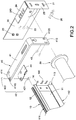
- this disclosure discloses a two-in-one curtain and roller blind support frame 1 comprising: a bonding board 10, a pair of frames 20, a roller blind shaft 30 and a plurality of positioning modules 40.
- the pair of frames 20 are symmetrically installed to both sides of the bonding board 10, and each pair of frames 20 have an end fixed to the bonding board 10 and the other end fixed to fixed surface such as a wall or a ceiling.
- the roller blind shaft 30 is coupled between the pair of frames 20 for combining a vertically up-and-down opening roller blind 3 and the bonding board 10 is provided for combining a sideway opening curtain 4.
- the positioning modules 40 has an end fixed to the bonding board 10 and the other end fixed to a wall.
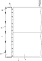
- the bonding board 10 comprises a board member 11 and a binding groove 12 and a curtain rail 13 formed on the board member 11; and a side of the curtain is installed on the curtain rail 13.
- the bonding board 10 is a hollow board, but this disclosure is not limited to such arrangement only.
- the board member 11 has a top surface 111, a bottom surface 112 and two opposite sides 113.
- the binding groove 12 is formed on the top surface 111; and the curtain rail 13 is formed on the bottom surface 112.
- a bent plate 14 is coupled to a side 113 of the board member 11 separately.
- each of the frames 20 has a plurality of first coupling holes 21, and the frame 20 is passed through the first coupling holes 21 and fixed to a fixed surface by the plurality of first locking elements 22.
- the bent plate 14 has at least one fixing hole 140.
- the fixing hole 140 is J-shaped.
- a side of the frame 20 facing the bent plate 14 has at least one positioning bump 23, and the frame 20 is positioned in the fixing hole 140 and fixed to the bent plate 14 by the positioning bump 23.
- roller blind shaft 30 is installed between the pair of frames 20, and both ends of the roller blind shaft 30 are fixed to the pair of frames 20 respectively to combine with a roller blind.
- each of the frames 20 is bent and extended to form a first covering plate 24 disposed on an upper side of the roller blind shaft 30 and a second covering plate 25 disposed on an outer side of the roller blind shaft 30.
- the first coupling holes 21 are formed on the second covering plate 25.
- each of the first covering plates 24 and each of the second covering plates 25 are perpendicular to each other and disposed on an outer side of the bonding board 10 away from the frame 20. It is noteworthy that the frames 20 (including the first covering plate 24 and the second covering plate 25 are mounted onto two sides of the roller blind shaft 30 respectively to shelter the light coming from both left and right sides to prevent the incidence of external light from a side of the roller blind shaft 30 and improve the shading effect.
- the first covering plate 24 has a plurality of second coupling holes 240; and the second coupling holes 240 are provided for the plurality of screws 26 to pass through and fix onto a ceiling, so as to improve the positioning effect and stability.
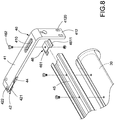
- each of the positioning modules 40 is spaced from each other and disposed between the pair of frames 20.
- Each of the positioning modules 40 comprises a positioning bracket 41 and a locking component 42.
- the positioning bracket 41 has a first end 411 and a second end 412 opposite to each other, and the first end 411 has a first through hole 4110, and the second end 412 has at least one second through hole 4120.
- the first end 411 is passed through by the locking component 42 and fixed to the binding groove 12 of the bonding board 10 by the first through hole 4110, and the second end 412 is passed through the second through hole 4120 and secured to a fixed surface 2 by a second locking element 43.
- each of the positioning brackets 41 is L-shaped.
- each of the positioning modules 40 further comprises a support plate 44 fixed to a bottom surface (112) of the positioning bracket 41 to improve the support of the positioning bracket 41.
- the two-in-one curtain and roller blind support frame 1 is mounted onto a fixed surface 2 and combined with a roller blind 3 and/or a curtain 4.
- the board member 11 is fixed onto the fixed surface 2; and the roller blind 3 is installed to the roller blind shaft 30, and the curtain 4 is hung onto the curtain rail 13 of the positioning bracket 41.
- the binding groove 12 of the bonding board 10 is a T-shaped groove; and the locking component 42 comprises a T-shaped screw seat 421 and a stud 422.
- the T-shaped screw seat 421 has a stop plate 4211 passing into the T-shaped groove and protruding from a screw hole 4212 of the T-shaped groove.
- the positioning bracket 41 is passed through the positioning bracket 41 and the screw hole 4212 and combined with the bonding board 10 by the stud 422.
- the two-in-one curtain and roller blind support frame 1 is combined with a roller blind 3 and a curtain 4.
- the roller blind 3 is situated at a vertically drooping status to shelter a window while the curtain 4 is situated at a sideway closed status to shelter the window.
- the roller blind 3 is situated at an upwardly rolled status, so that just the curtain 4 shelters the window only.
- the curtain 4 is opened sideway, so that just the roller blind 3 shelters the window only.
- the positioning modules 40 of the two-in-one curtain and roller blind support frame 1 further comprises an auxiliary support 45 and a plurality of auxiliary locking components 46.
- the stability of the roller blind shaft 30 can be improved by the auxiliary support of the auxiliary support 45 and the auxiliary locking components 46.
- the roller blind shaft 30 is fixed onto the auxiliary support 45 and combined with the positioning brackets 41 by the auxiliary locking components 46.
- the positioning brackets 41 have an auxiliary through hole 410; and each of the auxiliary locking components 46 comprises an auxiliary seat 461 and an auxiliary screw 462, and the auxiliary seat 461 is mounted onto the auxiliary support 45, and the positioning bracket 41 and the auxiliary support 45 are passed through the auxiliary through hole 410 and the auxiliary seat 461 for a connection by the auxiliary screw 462.
- the auxiliary support 45 is a U-shaped rail, and the auxiliary seat 461 has a pair of flaps 4611, and the auxiliary seat 461 is passed into the auxiliary support 45 by the pair of flaps 4611.
- the application of the two-in-one curtain and roller blind support frame 1 of the present disclosure may be adjusted according to the actual using requirement to improve the practicality of the present disclosure.
Landscapes
- Engineering & Computer Science (AREA)
- Structural Engineering (AREA)
- Architecture (AREA)
- Civil Engineering (AREA)
- Curtains And Furnishings For Windows Or Doors (AREA)
- Blinds (AREA)
Claims (13)
- Cadre de support de rideau et de volet roulant deux en un (1), ledit cadre (1) comprenant un rideau (4) disposé sur un rail à rideau (13), un arbre de volet roulant (30), dont les deux extrémités sont fixées à une paire de cadres (20) respectivement combinés avec le volet roulant (3), caractérisé en ce que ledit cadre (1) comprend en outre :un panneau de liaison (10), comprenant un élément de panneau (11) et une rainure de liaison (12) et ledit rail à rideau (13) formé sur l'élément de panneau (11), ladite paire de cadres (20), combinés avec les deux côtés de l'élément de panneau (11) respectivement, et chacun des cadres (20) ayant une pluralité de premiers trous de couplage (21), et passant à travers les premiers trous de couplage (21) étant fixé à une surface fixe (2) à travers le cadre par une pluralité de premiers éléments de verrouillage (22) ; etune pluralité de modules de positionnement (40), espacés les uns des autres et disposés entre la paire de cadres (20), chacun des modules de positionnement (40) comprenant un support de positionnement (41) et un composant de verrouillage (42), et le support de positionnement (41) ayant une première extrémité (411) et une seconde extrémité (412) opposées l'une à l'autre, et la première extrémité (411) ayant un premier trou traversant (4110), et la seconde extrémité (412) ayant au moins un second trou traversant (4120), et la première extrémité (411) étant passée à travers le premier trou traversant (4110) et fixée à la rainure de liaison (12) par le composant de verrouillage (4120), et la seconde extrémité (412) étant passée à travers le au moins un second trou traversant (4120) et fixée à la surface fixe (2) par au moins un second élément de verrouillage (43).
- Cadre de support de rideau et de volet roulant deux en un (1) selon la revendication 1, dans lequel l'élément de panneau (11) a une surface supérieure (111), une surface inférieure (112) et deux côtés opposés (113), et la rainure de liaison (12) est formée sur la surface supérieure (111), et le rail à rideau (13) est formé sur la surface inférieure (112), et une plaque pliée (14) est formée sur chacun des côtés, et la paire de cadres (20) est combinée avec les plaques pliées (14) respectivement.
- Cadre de support de rideau et de volet roulant deux en un (1) selon la revendication 2, dans lequel la plaque pliée (14) a au moins un trou de fixation (140), et un côté du cadre (20) faisant face à la plaque pliée (14) a au moins une bosse de positionnement (23), et le cadre (20) est positionné dans le trou de fixation (140) et fixé à la plaque pliée (14) par la bosse de positionnement (23).
- Cadre de support de rideau et de volet roulant deux en un (1) selon la revendication 3, dans lequel le trou de fixation (140) est en forme de J.
- Cadre de support de rideau et de volet roulant deux en un (1) selon la revendication 2, dans lequel la rainure de liaison (12) est une rainure en forme de T, et le composant de verrouillage comprend un siège de vis en forme de T (421) et un goujon (422), et le siège de vis en forme de T (421) a une plaque d'arrêt (4211) passant dans la rainure en forme de T et dépassant d'un trou de vis (4212) de la rainure en forme de T, et le trou de vis (4212) est passé à travers le support de positionnement (41) et combiné avec le panneau de liaison par le goujon (422).
- Cadre de support de rideau et de volet roulant deux en un (1) selon la revendication 1, dans lequel chacun des modules de positionnement (40) comprend en outre une plaque de support (44) fixée à une surface inférieure (112) du support de positionnement (41).
- Cadre de support de rideau et de volet roulant deux en un (1) selon la revendication 1, dans lequel chacun des cadres (20) a une première plaque de couverture (24) pliée et étendue disposée sur un côté supérieur de l'arbre de volet roulant (30) et une seconde plaque de couverture (25) disposée sur un côté extérieur de l'arbre de volet roulant (30).
- Cadre de support de rideau et de volet roulant deux en un (1) selon la revendication 7, dans lequel chacune des premières plaques de couverture et chacune des secondes plaques de couverture (25) sont perpendiculaires l'une à l'autre et disposées sur un côté du cadre faisant face à la surface fixe.
- Cadre de support de rideau et de volet roulant deux en un (1) selon la revendication 7, dans lequel la première plaque de couverture présente une pluralité de seconds trous de couplage (240) pour le passage et l'installation d'une pluralité de vis (26).
- Cadre de support de rideau et de volet roulant deux en un (1) selon la revendication 1, dans lequel chacun des cadres (20) est en forme de L.
- Cadre de support de rideau et de volet roulant deux en un (1) selon la revendication 1, dans lequel le module de positionnement (40) comprend en outre un support auxiliaire (45) et une pluralité de composants de verrouillage auxiliaires (46), et l'arbre de volet roulant (30) est fixé au support auxiliaire (45) et combiné aux supports de positionnement (41) par les composants de verrouillage auxiliaires (46).
- Cadre de support de rideau et de volet roulant deux en un (1) selon la revendication 11, dans lequel le support de positionnement (41) a un trou traversant auxiliaire (410), et chacun des composants de verrouillage auxiliaires (46) comprend un siège auxiliaire (461) et une vis auxiliaire (462), et le siège auxiliaire (461) est installé sur le support auxiliaire (45), et le support de positionnement (41) et le support auxiliaire (45) sont passés dans le trou traversant auxiliaire (410) et le siège auxiliaire (461) pour une connexion par la vis auxiliaire (462).
- Cadre de support de rideau et de volet roulant deux en un (1) selon la revendication 12, dans lequel le support auxiliaire (45) est un rail en forme de U, et le siège auxiliaire (461) comporte une paire de volets (4611), et le siège auxiliaire (461) est passé et installé dans le support auxiliaire (45) par la paire de volets (4611).
Applications Claiming Priority (1)
| Application Number | Priority Date | Filing Date | Title |
|---|---|---|---|
| TW107215759U TWM575055U (zh) | 2018-11-20 | 2018-11-20 | 雙合一的窗簾及捲簾支架 |
Publications (2)
| Publication Number | Publication Date |
|---|---|
| EP3656964A1 EP3656964A1 (fr) | 2020-05-27 |
| EP3656964B1 true EP3656964B1 (fr) | 2021-09-01 |
Family
ID=66591067
Family Applications (1)
| Application Number | Title | Priority Date | Filing Date |
|---|---|---|---|
| EP19208101.6A Active EP3656964B1 (fr) | 2018-11-20 | 2019-11-08 | Cadre de support pour rideau et store deux en un |
Country Status (4)
| Country | Link |
|---|---|
| US (1) | US20200154925A1 (fr) |
| EP (1) | EP3656964B1 (fr) |
| AU (1) | AU2019100746A4 (fr) |
| TW (1) | TWM575055U (fr) |
Families Citing this family (2)
| Publication number | Priority date | Publication date | Assignee | Title |
|---|---|---|---|---|
| US20240231424A1 (en) * | 2023-01-06 | 2024-07-11 | Eddie Smith | Computer screen blind device |
| CN121548679A (zh) * | 2023-06-07 | 2026-02-17 | 路创技术有限责任公司 | 用于窗帘饰板的锁定机构 |
Family Cites Families (2)
| Publication number | Priority date | Publication date | Assignee | Title |
|---|---|---|---|---|
| US10036162B2 (en) * | 2014-12-16 | 2018-07-31 | Geigtech East Bay Llc | Recessed shade and curtain storage and deployment system |
| CA2928261A1 (fr) * | 2015-05-07 | 2016-11-07 | Norbert Marocco | Rail de tete de parure de fenetre multiusage |
-
2018
- 2018-11-20 TW TW107215759U patent/TWM575055U/zh unknown
-
2019
- 2019-07-09 AU AU2019100746A patent/AU2019100746A4/en active Active
- 2019-10-13 US US16/600,546 patent/US20200154925A1/en not_active Abandoned
- 2019-11-08 EP EP19208101.6A patent/EP3656964B1/fr active Active
Also Published As
| Publication number | Publication date |
|---|---|
| AU2019100746A4 (en) | 2019-08-15 |
| EP3656964A1 (fr) | 2020-05-27 |
| TWM575055U (zh) | 2019-03-01 |
| US20200154925A1 (en) | 2020-05-21 |
Similar Documents
| Publication | Publication Date | Title |
|---|---|---|
| US20170204653A1 (en) | Adjustable shim and pre-hung door with the same | |
| EP3656964B1 (fr) | Cadre de support pour rideau et store deux en un | |
| US8833426B2 (en) | Screening arrangement comprising means for mounting side rails and method of mounting such a screening arrangement | |
| US20210404244A1 (en) | A Corner Bracket | |
| TWM542051U (zh) | 嵌板之安裝系統 | |
| JP6886541B2 (ja) | 開閉体収容ケースの取付構造、及び、開閉体収容ケースの取付方法 | |
| US20100115864A1 (en) | Adjustable Frame Assembly for Fire Rated Building Opening | |
| CA2953514C (fr) | Cale ajustable et porte montee comportant ladite cale | |
| KR102393066B1 (ko) | 미서기창의 창짝 구조 | |
| JP5255328B2 (ja) | 丁番スペーサ | |
| US20150059993A1 (en) | Window treatment mounting system | |
| JP2017043902A (ja) | 開閉体収容ケース、及び、開閉体収容ケースの取付方法 | |
| JP6530679B2 (ja) | 開閉体収容ケース | |
| KR102018426B1 (ko) | 재단 및 조립이 용이한 입면 분할 창호 | |
| JP7254607B2 (ja) | 建築用シャッター装置におけるガイドレール | |
| JP7710959B2 (ja) | シャッターにおける引っ掛け金具の固定構造 | |
| US20250020023A1 (en) | Window blind frame | |
| KR102697149B1 (ko) | 건축물의 무용접 프레임구조체 | |
| JP7851176B2 (ja) | 障子、建具及び障子の製造方法 | |
| JP6342630B2 (ja) | 開閉体収容ケース | |
| JP2013163968A (ja) | ドア | |
| JP7504830B2 (ja) | 窓 | |
| JP4659608B2 (ja) | 壁面装置 | |
| JP6297961B2 (ja) | サッシ用額縁 | |
| JPH0442469Y2 (fr) |
Legal Events
| Date | Code | Title | Description |
|---|---|---|---|
| PUAI | Public reference made under article 153(3) epc to a published international application that has entered the european phase |
Free format text: ORIGINAL CODE: 0009012 |
|
| STAA | Information on the status of an ep patent application or granted ep patent |
Free format text: STATUS: THE APPLICATION HAS BEEN PUBLISHED |
|
| AK | Designated contracting states |
Kind code of ref document: A1 Designated state(s): AL AT BE BG CH CY CZ DE DK EE ES FI FR GB GR HR HU IE IS IT LI LT LU LV MC MK MT NL NO PL PT RO RS SE SI SK SM TR |
|
| AX | Request for extension of the european patent |
Extension state: BA ME |
|
| STAA | Information on the status of an ep patent application or granted ep patent |
Free format text: STATUS: REQUEST FOR EXAMINATION WAS MADE |
|
| 17P | Request for examination filed |
Effective date: 20201127 |
|
| RBV | Designated contracting states (corrected) |
Designated state(s): AL AT BE BG CH CY CZ DE DK EE ES FI FR GB GR HR HU IE IS IT LI LT LU LV MC MK MT NL NO PL PT RO RS SE SI SK SM TR |
|
| GRAP | Despatch of communication of intention to grant a patent |
Free format text: ORIGINAL CODE: EPIDOSNIGR1 |
|
| STAA | Information on the status of an ep patent application or granted ep patent |
Free format text: STATUS: GRANT OF PATENT IS INTENDED |
|
| INTG | Intention to grant announced |
Effective date: 20210420 |
|
| GRAS | Grant fee paid |
Free format text: ORIGINAL CODE: EPIDOSNIGR3 |
|
| GRAA | (expected) grant |
Free format text: ORIGINAL CODE: 0009210 |
|
| STAA | Information on the status of an ep patent application or granted ep patent |
Free format text: STATUS: THE PATENT HAS BEEN GRANTED |
|
| AK | Designated contracting states |
Kind code of ref document: B1 Designated state(s): AL AT BE BG CH CY CZ DE DK EE ES FI FR GB GR HR HU IE IS IT LI LT LU LV MC MK MT NL NO PL PT RO RS SE SI SK SM TR |
|
| REG | Reference to a national code |
Ref country code: GB Ref legal event code: FG4D |
|
| REG | Reference to a national code |
Ref country code: CH Ref legal event code: EP Ref country code: AT Ref legal event code: REF Ref document number: 1426439 Country of ref document: AT Kind code of ref document: T Effective date: 20210915 |
|
| REG | Reference to a national code |
Ref country code: DE Ref legal event code: R096 Ref document number: 602019007344 Country of ref document: DE |
|
| REG | Reference to a national code |
Ref country code: IE Ref legal event code: FG4D |
|
| REG | Reference to a national code |
Ref country code: LT Ref legal event code: MG9D |
|
| REG | Reference to a national code |
Ref country code: NL Ref legal event code: MP Effective date: 20210901 |
|
| PG25 | Lapsed in a contracting state [announced via postgrant information from national office to epo] |
Ref country code: SE Free format text: LAPSE BECAUSE OF FAILURE TO SUBMIT A TRANSLATION OF THE DESCRIPTION OR TO PAY THE FEE WITHIN THE PRESCRIBED TIME-LIMIT Effective date: 20210901 Ref country code: RS Free format text: LAPSE BECAUSE OF FAILURE TO SUBMIT A TRANSLATION OF THE DESCRIPTION OR TO PAY THE FEE WITHIN THE PRESCRIBED TIME-LIMIT Effective date: 20210901 Ref country code: ES Free format text: LAPSE BECAUSE OF FAILURE TO SUBMIT A TRANSLATION OF THE DESCRIPTION OR TO PAY THE FEE WITHIN THE PRESCRIBED TIME-LIMIT Effective date: 20210901 Ref country code: LT Free format text: LAPSE BECAUSE OF FAILURE TO SUBMIT A TRANSLATION OF THE DESCRIPTION OR TO PAY THE FEE WITHIN THE PRESCRIBED TIME-LIMIT Effective date: 20210901 Ref country code: BG Free format text: LAPSE BECAUSE OF FAILURE TO SUBMIT A TRANSLATION OF THE DESCRIPTION OR TO PAY THE FEE WITHIN THE PRESCRIBED TIME-LIMIT Effective date: 20211201 Ref country code: FI Free format text: LAPSE BECAUSE OF FAILURE TO SUBMIT A TRANSLATION OF THE DESCRIPTION OR TO PAY THE FEE WITHIN THE PRESCRIBED TIME-LIMIT Effective date: 20210901 Ref country code: HR Free format text: LAPSE BECAUSE OF FAILURE TO SUBMIT A TRANSLATION OF THE DESCRIPTION OR TO PAY THE FEE WITHIN THE PRESCRIBED TIME-LIMIT Effective date: 20210901 Ref country code: NO Free format text: LAPSE BECAUSE OF FAILURE TO SUBMIT A TRANSLATION OF THE DESCRIPTION OR TO PAY THE FEE WITHIN THE PRESCRIBED TIME-LIMIT Effective date: 20211201 |
|
| REG | Reference to a national code |
Ref country code: AT Ref legal event code: MK05 Ref document number: 1426439 Country of ref document: AT Kind code of ref document: T Effective date: 20210901 |
|
| PG25 | Lapsed in a contracting state [announced via postgrant information from national office to epo] |
Ref country code: PL Free format text: LAPSE BECAUSE OF FAILURE TO SUBMIT A TRANSLATION OF THE DESCRIPTION OR TO PAY THE FEE WITHIN THE PRESCRIBED TIME-LIMIT Effective date: 20210901 Ref country code: LV Free format text: LAPSE BECAUSE OF FAILURE TO SUBMIT A TRANSLATION OF THE DESCRIPTION OR TO PAY THE FEE WITHIN THE PRESCRIBED TIME-LIMIT Effective date: 20210901 Ref country code: GR Free format text: LAPSE BECAUSE OF FAILURE TO SUBMIT A TRANSLATION OF THE DESCRIPTION OR TO PAY THE FEE WITHIN THE PRESCRIBED TIME-LIMIT Effective date: 20211202 |
|
| PG25 | Lapsed in a contracting state [announced via postgrant information from national office to epo] |
Ref country code: AT Free format text: LAPSE BECAUSE OF FAILURE TO SUBMIT A TRANSLATION OF THE DESCRIPTION OR TO PAY THE FEE WITHIN THE PRESCRIBED TIME-LIMIT Effective date: 20210901 |
|
| PG25 | Lapsed in a contracting state [announced via postgrant information from national office to epo] |
Ref country code: IS Free format text: LAPSE BECAUSE OF FAILURE TO SUBMIT A TRANSLATION OF THE DESCRIPTION OR TO PAY THE FEE WITHIN THE PRESCRIBED TIME-LIMIT Effective date: 20220101 Ref country code: SM Free format text: LAPSE BECAUSE OF FAILURE TO SUBMIT A TRANSLATION OF THE DESCRIPTION OR TO PAY THE FEE WITHIN THE PRESCRIBED TIME-LIMIT Effective date: 20210901 Ref country code: SK Free format text: LAPSE BECAUSE OF FAILURE TO SUBMIT A TRANSLATION OF THE DESCRIPTION OR TO PAY THE FEE WITHIN THE PRESCRIBED TIME-LIMIT Effective date: 20210901 Ref country code: RO Free format text: LAPSE BECAUSE OF FAILURE TO SUBMIT A TRANSLATION OF THE DESCRIPTION OR TO PAY THE FEE WITHIN THE PRESCRIBED TIME-LIMIT Effective date: 20210901 Ref country code: PT Free format text: LAPSE BECAUSE OF FAILURE TO SUBMIT A TRANSLATION OF THE DESCRIPTION OR TO PAY THE FEE WITHIN THE PRESCRIBED TIME-LIMIT Effective date: 20220103 Ref country code: NL Free format text: LAPSE BECAUSE OF FAILURE TO SUBMIT A TRANSLATION OF THE DESCRIPTION OR TO PAY THE FEE WITHIN THE PRESCRIBED TIME-LIMIT Effective date: 20210901 Ref country code: EE Free format text: LAPSE BECAUSE OF FAILURE TO SUBMIT A TRANSLATION OF THE DESCRIPTION OR TO PAY THE FEE WITHIN THE PRESCRIBED TIME-LIMIT Effective date: 20210901 Ref country code: CZ Free format text: LAPSE BECAUSE OF FAILURE TO SUBMIT A TRANSLATION OF THE DESCRIPTION OR TO PAY THE FEE WITHIN THE PRESCRIBED TIME-LIMIT Effective date: 20210901 Ref country code: AL Free format text: LAPSE BECAUSE OF FAILURE TO SUBMIT A TRANSLATION OF THE DESCRIPTION OR TO PAY THE FEE WITHIN THE PRESCRIBED TIME-LIMIT Effective date: 20210901 |
|
| REG | Reference to a national code |
Ref country code: DE Ref legal event code: R097 Ref document number: 602019007344 Country of ref document: DE |
|
| PG25 | Lapsed in a contracting state [announced via postgrant information from national office to epo] |
Ref country code: MC Free format text: LAPSE BECAUSE OF FAILURE TO SUBMIT A TRANSLATION OF THE DESCRIPTION OR TO PAY THE FEE WITHIN THE PRESCRIBED TIME-LIMIT Effective date: 20210901 |
|
| PLBE | No opposition filed within time limit |
Free format text: ORIGINAL CODE: 0009261 |
|
| STAA | Information on the status of an ep patent application or granted ep patent |
Free format text: STATUS: NO OPPOSITION FILED WITHIN TIME LIMIT |
|
| PG25 | Lapsed in a contracting state [announced via postgrant information from national office to epo] |
Ref country code: LU Free format text: LAPSE BECAUSE OF NON-PAYMENT OF DUE FEES Effective date: 20211108 Ref country code: IT Free format text: LAPSE BECAUSE OF FAILURE TO SUBMIT A TRANSLATION OF THE DESCRIPTION OR TO PAY THE FEE WITHIN THE PRESCRIBED TIME-LIMIT Effective date: 20210901 Ref country code: DK Free format text: LAPSE BECAUSE OF FAILURE TO SUBMIT A TRANSLATION OF THE DESCRIPTION OR TO PAY THE FEE WITHIN THE PRESCRIBED TIME-LIMIT Effective date: 20210901 Ref country code: BE Free format text: LAPSE BECAUSE OF NON-PAYMENT OF DUE FEES Effective date: 20211130 |
|
| REG | Reference to a national code |
Ref country code: BE Ref legal event code: MM Effective date: 20211130 |
|
| 26N | No opposition filed |
Effective date: 20220602 |
|
| PG25 | Lapsed in a contracting state [announced via postgrant information from national office to epo] |
Ref country code: SI Free format text: LAPSE BECAUSE OF FAILURE TO SUBMIT A TRANSLATION OF THE DESCRIPTION OR TO PAY THE FEE WITHIN THE PRESCRIBED TIME-LIMIT Effective date: 20210901 |
|
| PG25 | Lapsed in a contracting state [announced via postgrant information from national office to epo] |
Ref country code: IE Free format text: LAPSE BECAUSE OF NON-PAYMENT OF DUE FEES Effective date: 20211108 |
|
| PG25 | Lapsed in a contracting state [announced via postgrant information from national office to epo] |
Ref country code: CY Free format text: LAPSE BECAUSE OF FAILURE TO SUBMIT A TRANSLATION OF THE DESCRIPTION OR TO PAY THE FEE WITHIN THE PRESCRIBED TIME-LIMIT Effective date: 20210901 |
|
| REG | Reference to a national code |
Ref country code: CH Ref legal event code: PL |
|
| PG25 | Lapsed in a contracting state [announced via postgrant information from national office to epo] |
Ref country code: LI Free format text: LAPSE BECAUSE OF NON-PAYMENT OF DUE FEES Effective date: 20221130 Ref country code: HU Free format text: LAPSE BECAUSE OF FAILURE TO SUBMIT A TRANSLATION OF THE DESCRIPTION OR TO PAY THE FEE WITHIN THE PRESCRIBED TIME-LIMIT; INVALID AB INITIO Effective date: 20191108 Ref country code: CH Free format text: LAPSE BECAUSE OF NON-PAYMENT OF DUE FEES Effective date: 20221130 |
|
| PG25 | Lapsed in a contracting state [announced via postgrant information from national office to epo] |
Ref country code: MK Free format text: LAPSE BECAUSE OF FAILURE TO SUBMIT A TRANSLATION OF THE DESCRIPTION OR TO PAY THE FEE WITHIN THE PRESCRIBED TIME-LIMIT Effective date: 20210901 |
|
| PG25 | Lapsed in a contracting state [announced via postgrant information from national office to epo] |
Ref country code: TR Free format text: LAPSE BECAUSE OF FAILURE TO SUBMIT A TRANSLATION OF THE DESCRIPTION OR TO PAY THE FEE WITHIN THE PRESCRIBED TIME-LIMIT Effective date: 20210901 |
|
| PG25 | Lapsed in a contracting state [announced via postgrant information from national office to epo] |
Ref country code: MT Free format text: LAPSE BECAUSE OF FAILURE TO SUBMIT A TRANSLATION OF THE DESCRIPTION OR TO PAY THE FEE WITHIN THE PRESCRIBED TIME-LIMIT Effective date: 20210901 |
|
| PGFP | Annual fee paid to national office [announced via postgrant information from national office to epo] |
Ref country code: DE Payment date: 20251128 Year of fee payment: 7 |
|
| PGFP | Annual fee paid to national office [announced via postgrant information from national office to epo] |
Ref country code: GB Payment date: 20251128 Year of fee payment: 7 |
|
| PGFP | Annual fee paid to national office [announced via postgrant information from national office to epo] |
Ref country code: FR Payment date: 20251020 Year of fee payment: 7 |