EP3657009A1 - Verfahren zur verbesserung der betriebseffizienz von wasserturbinen und zur reduzierung der kavitation von komponenten davon - Google Patents
Verfahren zur verbesserung der betriebseffizienz von wasserturbinen und zur reduzierung der kavitation von komponenten davon Download PDFInfo
- Publication number
- EP3657009A1 EP3657009A1 EP18208192.7A EP18208192A EP3657009A1 EP 3657009 A1 EP3657009 A1 EP 3657009A1 EP 18208192 A EP18208192 A EP 18208192A EP 3657009 A1 EP3657009 A1 EP 3657009A1
- Authority
- EP
- European Patent Office
- Prior art keywords
- water
- turbine
- penstock
- air
- air guiding
- Prior art date
- Legal status (The legal status is an assumption and is not a legal conclusion. Google has not performed a legal analysis and makes no representation as to the accuracy of the status listed.)
- Withdrawn
Links
Images





Classifications
-
- F—MECHANICAL ENGINEERING; LIGHTING; HEATING; WEAPONS; BLASTING
- F03—MACHINES OR ENGINES FOR LIQUIDS; WIND, SPRING, OR WEIGHT MOTORS; PRODUCING MECHANICAL POWER OR A REACTIVE PROPULSIVE THRUST, NOT OTHERWISE PROVIDED FOR
- F03B—MACHINES OR ENGINES FOR LIQUIDS
- F03B11/00—Parts or details not provided for in, or of interest apart from, the preceding groups, e.g. wear-protection couplings, between turbine and generator
- F03B11/002—Injecting air or other fluid
-
- F—MECHANICAL ENGINEERING; LIGHTING; HEATING; WEAPONS; BLASTING
- F03—MACHINES OR ENGINES FOR LIQUIDS; WIND, SPRING, OR WEIGHT MOTORS; PRODUCING MECHANICAL POWER OR A REACTIVE PROPULSIVE THRUST, NOT OTHERWISE PROVIDED FOR
- F03B—MACHINES OR ENGINES FOR LIQUIDS
- F03B11/00—Parts or details not provided for in, or of interest apart from, the preceding groups, e.g. wear-protection couplings, between turbine and generator
- F03B11/04—Parts or details not provided for in, or of interest apart from, the preceding groups, e.g. wear-protection couplings, between turbine and generator for diminishing cavitation or vibration, e.g. balancing
-
- F—MECHANICAL ENGINEERING; LIGHTING; HEATING; WEAPONS; BLASTING
- F05—INDEXING SCHEMES RELATING TO ENGINES OR PUMPS IN VARIOUS SUBCLASSES OF CLASSES F01-F04
- F05B—INDEXING SCHEME RELATING TO WIND, SPRING, WEIGHT, INERTIA OR LIKE MOTORS, TO MACHINES OR ENGINES FOR LIQUIDS COVERED BY SUBCLASSES F03B, F03D AND F03G
- F05B2220/00—Application
- F05B2220/64—Application for aeration
-
- Y—GENERAL TAGGING OF NEW TECHNOLOGICAL DEVELOPMENTS; GENERAL TAGGING OF CROSS-SECTIONAL TECHNOLOGIES SPANNING OVER SEVERAL SECTIONS OF THE IPC; TECHNICAL SUBJECTS COVERED BY FORMER USPC CROSS-REFERENCE ART COLLECTIONS [XRACs] AND DIGESTS
- Y02—TECHNOLOGIES OR APPLICATIONS FOR MITIGATION OR ADAPTATION AGAINST CLIMATE CHANGE
- Y02E—REDUCTION OF GREENHOUSE GAS [GHG] EMISSIONS, RELATED TO ENERGY GENERATION, TRANSMISSION OR DISTRIBUTION
- Y02E10/00—Energy generation through renewable energy sources
- Y02E10/20—Hydro energy
-
- Y—GENERAL TAGGING OF NEW TECHNOLOGICAL DEVELOPMENTS; GENERAL TAGGING OF CROSS-SECTIONAL TECHNOLOGIES SPANNING OVER SEVERAL SECTIONS OF THE IPC; TECHNICAL SUBJECTS COVERED BY FORMER USPC CROSS-REFERENCE ART COLLECTIONS [XRACs] AND DIGESTS
- Y02—TECHNOLOGIES OR APPLICATIONS FOR MITIGATION OR ADAPTATION AGAINST CLIMATE CHANGE
- Y02P—CLIMATE CHANGE MITIGATION TECHNOLOGIES IN THE PRODUCTION OR PROCESSING OF GOODS
- Y02P70/00—Climate change mitigation technologies in the production process for final industrial or consumer products
- Y02P70/50—Manufacturing or production processes characterised by the final manufactured product
Definitions
- the present invention relates to a method to enhance operation efficiency of water turbines and to reduce cavitation of components thereof.
- a water turbine 300 has a penstock 200 installed on a dam 100 at a hydroelectric power station and the penstock has an entry 201 and an exit 202 for the water to flow through the entry 201 of the water penstock 200 from the top to the bottom of the exit 202 to the water turbine 300 , and the water turbine 300 rotates and drives a generator 400 connected thereto to generate electrical energy.
- the water turbine can be roughly classified into an impulse turbine and a reaction turbine according to its working principle.
- the impulse turbine uses a high-speed water flow impacting runner blade or water bucket 302a for work
- the main representative model is a Pelton Turbine 300a as shown in Fig. 2A .
- the reaction turbine the pressure and kinetic energy of the water are used to perform work
- the main representative model is shown in Fig. 2B , a Francis Turbine 300b using the runner blades 302b , and Fig. 2C , a Kaplan Turbine 300c using a spiral propeller blade 302c .
- the water head position can be used to drive the runner blades, and the outer structure can be roughly divided into: non-closed casing 301a , as shown in FIG. 2A .
- Pelton Turbine and closed casing 301b , such as the Francis Turbine shown in Fig. 2B , and the Kaplan Turbine shown in Fig. 2C .
- a primary objective the present invention is to provide a method for improving the power generation efficiency of a water turbine and suppressing cavitation of a turbine component.
- the water turbine is a reaction turbine having a closed casing and a connecting section connected to the exit of the penstock
- the air guiding device includes at least one air guiding tube which is arranged on the pipe section before the exit or on the connecting section.
- the air guiding device further includes an annulus periphery and an annular output passage formed inside the annulus periphery , and the at least one air guiding tube is disposed on the annulus periphery .
- the reaction turbine includes a Francis turbine or a Kaplan turbine.
- the water turbine is an impulse turbine and the exit of the penstock is extended to the plurality of runner blades of the impulse turbine as the air guiding device is disposed at a front of the exit .
- the impulse turbine includes a Pelton turbine.
- the air control valve is either manual or automatic.
- the air control valve is closed when the water flow in the penstock is not flowing at high speed, and the air control valve is opened when the water flow in the penstock is flowing at high speed.
- the present invention can provide an air guiding device disposed between the penstock and the plurality of runner blades of the water turbine, and use the Bernoulli's Principle and the reservoir without changing any original design inside the water turbine.
- a high-speed water flow can be generated by the water head.
- the high-speed water flow forms a negative pressure at the air guiding device to absorb the external air and mix with the water to produce a water flow containing a large amount of pressurized bubbles; since the cavitation phenomenon is mainly due to high speed the water flow impacts the runner blade, and the low pressure part is lower than the vapor pressure of the water, causing the water to vaporize and generate air bubbles, which causes erosion of the relevant components inside the water turbine, thus affecting the power and service life of the water turbine; since the high pressure bubble of the invention has compressibility, it will not break when compressed, but conventionally, cavities in the water flow cavitation will rupture.
- the pressured air bubbles of the present invention can not only increase the force of the water flow to enhance the operation efficiency of the water turbine, but also contain pressurized air bubbles in the water flow and suppress the occurrence of cavitation in the low pressure area, so as to prevent the occurrence of cavitation in the runner blades and related components.
- the following provides a preferred embodiment of the technical features of the present invention; however, there are many types of water turbines, and the shapes and structures are not completely the same. Therefore, although only the preferred embodiment is described, the technical means used thereof are the same, so they are not described one by one.
- the water turbine parts and accessories described below include related components such as water turbine parts and accessories.
- Another runner blade may also be referred to as an impeller.
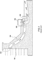
- a method to enhance operation efficiency of water turbines and to reduce cavitation of components thereof comprising: having a penstock 20 installed on a dam 10 at a hydroelectric power station, said penstock having an entry 21 at an upper end and an exit 22 at a lower end; having a water turbine 30 with a casing 31 and a plurality of runner blades 32 disposed inside said casing 31 , said water turbine 30 connected to said exit 22 of the penstock 20 for driving said runner blades 32 by hydropower produced by the water flowing out from the penstock 20 , the runner blades 32 is driven by the water flow pressure of the penstock 20 to drive a generator 50 , however, the device and the basic structure of the general hydroelectric power station are formed, and the principle and function are not described herein.
- the pipe section 33 described below in the present invention refers to a position which is provided before the exit 22 and a section of the connecting section 33a .
- an air guiding device 40 is disposed between the penstock 20 and the plurality of runner blades 32 of the water turbine 30 , said air guiding device 40 including at least one air guiding tube 41 penetrating into a pipe section 33 formed by the exit 22 of the penstock 20 and a connecting section 33a between the exit 22 and the water turbine 30 , said air guiding tube 41 having an inlet 411 at an upper end for guiding in external air and an outlet 412 at a lower end penetrating into the pipe section 33 ; and an air control valve 413 is disposed in the air guiding tube 41 between the inlet 411 and the outlet 412 .
- the water turbine 30 is a reaction turbine 30a .
- the reaction turbine 30a includes a Francis turbine or a Kaplan turbine. in the present embodiment, the reaction turbine 30a is a Francis turbine; having a closed casing 31a and a connecting section 33a connected to the exit 22 of the penstock 20 , and the air guiding device 40 includes at least one air guiding tube 41 which is arranged on the pipe section 33a before the exit 22 or on the connecting section 33a .
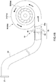
- the air guiding device 40 is disposed on the periphery of the exit 22 of the penstock 20 , but is not limited thereto; the air guiding device 40 may also be as shown in the fig. 4B , disposed on the connecting section 33a ; the air guiding device 40 of the present invention is disposed on the periphery of the exit 22 of the penstock 20 , or is disposed in the connecting section 33a , it can be implemented.
- the air control valve 413 is either manual or automatic.
- the air control valve 413 is that when the water flow from the top of the penstock 20 starts to drive the runner blades 32 , the high-speed water flow state has not yet been reached, so that the negative pressure generated by the outlet 412 cannot introduce the air at this time, so the air control valve 413 must be closed, otherwise the water flow will be ejected from the outlet 412 and poured into the inlet 411 .
- the air control valve 413 is opened, and at this time, the negative pressure is formed at the outlet 412 of the air guiding tube 41 by high-speed water flow h to take in external air a and then form a plurality of pressured air bubbles b in the water w .
- the outlet 412 is positioned adjacent to the exit 22 because the exit 22 has a relatively fast flow of water at this location.
- the outlet 412 disclosed in the present invention may have a circular hole shape, but is not limited thereto, and may be other shapes. Further, in the present embodiment, the outlet 412 is inclined rearward. This is a preferred embodiment. It has been found in an experiment that the outlet 412 is disposed perpendicular to the penstock 20 , and can also be implemented, that is, the high pressure water flow can also generate a negative pressure suction force at the outlet 412 .
- the air guiding device 40 further includes an annulus periphery 42 and an annular output passage 422 connecting to the penstock 20 or to the pipe section 33a of the water turbine 30 , and the at least one air guiding tube 41 is disposed on the annulus periphery 42 . Then the negative pressure formed at both the annular output passage 422 and the outlet 412 of the air guiding tube 41 by high-speed water flow h out from the penstock 20 takes in external air a and then forms a plurality of pressured air bubbles b in the water w .
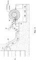
- FIG.9 is a schematic diagram illustrating an application example of the present invention in an embodiment; the present invention use the plurality of pressured air bubbles b are produced by a head of the water and then mixed into the water w by the air guiding device 40 , driving the runner blades 32 by the water flow h as volumes of the pressured air bubbles b increased at a decompressed area of the water turbine 30 , so as to enhance operation efficiency of the water turbine 30 with the enhanced water kinetic energy and to reduce formation of cavities in the water and prevent components of the water turbine 30 from damages caused by cavitation.
- FIG. 10 is another schematic diagram illustrating the application example of the present invention in an embodiment; in the present embodiment, the water turbine 30 is a Kaplan turbine 30b . It also belongs to the type of the reaction turbine 30a , and has a closed casing 31b . The difference is only that the runner blade 32 is a spiral rotating blade 32c , so the air guiding device 40 can also be applied, and is used in France turbine, the same effect cannot be described.
- FIG. 11 is a schematic diagram of the present invention in another embodiment, showing the water turbine having an open casing
- FIG. 12 is a schematic diagram illustrating an application example of the present invention in another embodiment.
- the same structure as the previous embodiment is denoted by the same reference numeral, and the difference is only that the water turbine 30 is an impact turbine 30c , belonging to the non-closed casing 31c , and the exit 22 of the penstock 20 extends to the impact.
- the periphery of the spiral rotating blade 32c of the impact turbine 30c , and the air guiding device 40 is provided on the periphery of the exit 22 .
- the impact turbine 30c includes a Pelton Turbine, and the casing 31 is a non-closed casing 31c , and the runner blade 32 is a bucket-shaped impeller 32d .
- a regulating valve 23 is disposed in front of the exit 22 of the penstock 20 for adjusting the water flow rate of the exit 22 .
- the regulating valve 23 belongs to the prior art, and is not the patent of the present invention. Therefore, whether it is a commercially available type of water turbine, such as a closed casing of Francis turbine, a Kaplan turbine, and a non-closed casing of Pelton turbine; the technical means of the air guiding device 40 of the present invention are.
- the air guiding device 40 can introduce the gas by an auxiliary means, including the exhaust gas of the hydroelectric power station, and feed it into the air pipe (not shown). Therefore, it belongs to resource recycling and reuse, which will not increase resources and increase costs. Further, if the present invention requires pressurized gas injection and is released from the outlet 412 , a higher propulsion power effect can be obtained, so that a plurality of power effects can be obtained with a small amount of.
Landscapes
- Engineering & Computer Science (AREA)
- Chemical & Material Sciences (AREA)
- Combustion & Propulsion (AREA)
- Mechanical Engineering (AREA)
- General Engineering & Computer Science (AREA)
- Hydraulic Turbines (AREA)
Priority Applications (1)
| Application Number | Priority Date | Filing Date | Title |
|---|---|---|---|
| EP18208192.7A EP3657009A1 (de) | 2018-11-24 | 2018-11-24 | Verfahren zur verbesserung der betriebseffizienz von wasserturbinen und zur reduzierung der kavitation von komponenten davon |
Applications Claiming Priority (1)
| Application Number | Priority Date | Filing Date | Title |
|---|---|---|---|
| EP18208192.7A EP3657009A1 (de) | 2018-11-24 | 2018-11-24 | Verfahren zur verbesserung der betriebseffizienz von wasserturbinen und zur reduzierung der kavitation von komponenten davon |
Publications (1)
| Publication Number | Publication Date |
|---|---|
| EP3657009A1 true EP3657009A1 (de) | 2020-05-27 |
Family
ID=64476957
Family Applications (1)
| Application Number | Title | Priority Date | Filing Date |
|---|---|---|---|
| EP18208192.7A Withdrawn EP3657009A1 (de) | 2018-11-24 | 2018-11-24 | Verfahren zur verbesserung der betriebseffizienz von wasserturbinen und zur reduzierung der kavitation von komponenten davon |
Country Status (1)
| Country | Link |
|---|---|
| EP (1) | EP3657009A1 (de) |
Cited By (1)
| Publication number | Priority date | Publication date | Assignee | Title |
|---|---|---|---|---|
| CN119086044A (zh) * | 2024-07-25 | 2024-12-06 | 中国长江电力股份有限公司 | 一种水轮发电机组大轴补气阀监测装置 |
Citations (4)
| Publication number | Priority date | Publication date | Assignee | Title |
|---|---|---|---|---|
| DE279351C (de) * | ||||
| DE1243119B (de) * | 1964-03-28 | 1967-06-22 | Neyrpic Ets | Verfahren und Einrichtung zum Betrieb einer umsteuerbaren Stroemungsmaschine fuer Fluessigkeiten, insbesondere einer Pumpenturbine |
| JPS59213951A (ja) * | 1983-05-19 | 1984-12-03 | Toshiba Corp | 水力機械の給気方法 |
| JPS6011686A (ja) * | 1983-06-29 | 1985-01-21 | Toshiba Corp | フランシス型水力機械 |
-
2018
- 2018-11-24 EP EP18208192.7A patent/EP3657009A1/de not_active Withdrawn
Patent Citations (4)
| Publication number | Priority date | Publication date | Assignee | Title |
|---|---|---|---|---|
| DE279351C (de) * | ||||
| DE1243119B (de) * | 1964-03-28 | 1967-06-22 | Neyrpic Ets | Verfahren und Einrichtung zum Betrieb einer umsteuerbaren Stroemungsmaschine fuer Fluessigkeiten, insbesondere einer Pumpenturbine |
| JPS59213951A (ja) * | 1983-05-19 | 1984-12-03 | Toshiba Corp | 水力機械の給気方法 |
| JPS6011686A (ja) * | 1983-06-29 | 1985-01-21 | Toshiba Corp | フランシス型水力機械 |
Cited By (1)
| Publication number | Priority date | Publication date | Assignee | Title |
|---|---|---|---|---|
| CN119086044A (zh) * | 2024-07-25 | 2024-12-06 | 中国长江电力股份有限公司 | 一种水轮发电机组大轴补气阀监测装置 |
Similar Documents
| Publication | Publication Date | Title |
|---|---|---|
| US10697423B2 (en) | Method to enhance operation efficiency of water turbines and to reduce cavitation of components thereof | |
| CN102384005A (zh) | 二级喷射冲击式水轮机 | |
| CA3025151A1 (en) | A method to enhance operation efficiency of water turbines and to reduce cavitation of components thereof | |
| CN101956641B (zh) | 一种水平轴潮流发电水轮机的导流装置 | |
| CN111486045A (zh) | 一种高效节能发电设备及其发电方法 | |
| EP3657009A1 (de) | Verfahren zur verbesserung der betriebseffizienz von wasserturbinen und zur reduzierung der kavitation von komponenten davon | |
| US20040197215A1 (en) | Method of converting storage pumps into reversible pump-turbines | |
| CN201757019U (zh) | 一种水轮机叶轮结构 | |
| CN201202576Y (zh) | 水斗冲击式水轮机 | |
| CN101705903B (zh) | 叶轮式海浪发电设备 | |
| CN114623035B (zh) | 一种水泵水轮机补气结构 | |
| CN111022241B (zh) | 一种提升水轮机发电效率及抑止水轮机零配件空蚀的方法 | |
| CN110454401A (zh) | 一种使江水上山的水能提水装置 | |
| CN217440201U (zh) | 一种可调节进水角度的水轮机 | |
| CN204900140U (zh) | 一种水轮机进水通道 | |
| CN213331372U (zh) | 一种易于装配的水轮机 | |
| CN108488021A (zh) | 摩天轮水轮机发电装置 | |
| WO2022032643A1 (zh) | 一种水轮机和水力发电机 | |
| CN221503532U (zh) | 一种离心泵叶轮密封结构 | |
| JP2020084956A (ja) | タービン装置の動作方法 | |
| CN110725769A (zh) | 一种大流量混流式水轮机提高效率的静叶装置及设计方法 | |
| CN114526185B (zh) | 一种自适应调控防空化水泵水轮机 | |
| CN221879584U (zh) | 一种低水压水流发电机装置 | |
| Zhang et al. | Research on Internal Flow Characteristics in the Buckets of Pelton Turbines under Kilometer-Head Range | |
| CN217078644U (zh) | 一种带有联排水斗式水轮机的溢流坝导墙 |
Legal Events
| Date | Code | Title | Description |
|---|---|---|---|
| PUAI | Public reference made under article 153(3) epc to a published international application that has entered the european phase |
Free format text: ORIGINAL CODE: 0009012 |
|
| STAA | Information on the status of an ep patent application or granted ep patent |
Free format text: STATUS: THE APPLICATION HAS BEEN PUBLISHED |
|
| AK | Designated contracting states |
Kind code of ref document: A1 Designated state(s): AL AT BE BG CH CY CZ DE DK EE ES FI FR GB GR HR HU IE IS IT LI LT LU LV MC MK MT NL NO PL PT RO RS SE SI SK SM TR |
|
| AX | Request for extension of the european patent |
Extension state: BA ME |
|
| STAA | Information on the status of an ep patent application or granted ep patent |
Free format text: STATUS: REQUEST FOR EXAMINATION WAS MADE |
|
| 17P | Request for examination filed |
Effective date: 20200922 |
|
| RBV | Designated contracting states (corrected) |
Designated state(s): AL AT BE BG CH CY CZ DE DK EE ES FI FR GB GR HR HU IE IS IT LI LT LU LV MC MK MT NL NO PL PT RO RS SE SI SK SM TR |
|
| STAA | Information on the status of an ep patent application or granted ep patent |
Free format text: STATUS: EXAMINATION IS IN PROGRESS |
|
| 17Q | First examination report despatched |
Effective date: 20210211 |
|
| GRAP | Despatch of communication of intention to grant a patent |
Free format text: ORIGINAL CODE: EPIDOSNIGR1 |
|
| STAA | Information on the status of an ep patent application or granted ep patent |
Free format text: STATUS: GRANT OF PATENT IS INTENDED |
|
| INTG | Intention to grant announced |
Effective date: 20220520 |
|
| STAA | Information on the status of an ep patent application or granted ep patent |
Free format text: STATUS: THE APPLICATION IS DEEMED TO BE WITHDRAWN |
|
| 18D | Application deemed to be withdrawn |
Effective date: 20221001 |