EP3657164A1 - Dispositif et procédé de détection de formation de moisissure - Google Patents
Dispositif et procédé de détection de formation de moisissure Download PDFInfo
- Publication number
- EP3657164A1 EP3657164A1 EP18207976.4A EP18207976A EP3657164A1 EP 3657164 A1 EP3657164 A1 EP 3657164A1 EP 18207976 A EP18207976 A EP 18207976A EP 3657164 A1 EP3657164 A1 EP 3657164A1
- Authority
- EP
- European Patent Office
- Prior art keywords
- dye
- detection
- change
- sensitive
- designed
- Prior art date
- Legal status (The legal status is an assumption and is not a legal conclusion. Google has not performed a legal analysis and makes no representation as to the accuracy of the status listed.)
- Withdrawn
Links
Images


Classifications
-
- G—PHYSICS
- G01—MEASURING; TESTING
- G01N—INVESTIGATING OR ANALYSING MATERIALS BY DETERMINING THEIR CHEMICAL OR PHYSICAL PROPERTIES
- G01N21/00—Investigating or analysing materials by the use of optical means, i.e. using sub-millimetre waves, infrared, visible or ultraviolet light
- G01N21/75—Systems in which material is subjected to a chemical reaction, the progress or the result of the reaction being investigated
- G01N21/77—Systems in which material is subjected to a chemical reaction, the progress or the result of the reaction being investigated by observing the effect on a chemical indicator
- G01N21/78—Systems in which material is subjected to a chemical reaction, the progress or the result of the reaction being investigated by observing the effect on a chemical indicator producing a change of colour
- G01N21/783—Systems in which material is subjected to a chemical reaction, the progress or the result of the reaction being investigated by observing the effect on a chemical indicator producing a change of colour for analysing gases
-
- G—PHYSICS
- G01—MEASURING; TESTING
- G01N—INVESTIGATING OR ANALYSING MATERIALS BY DETERMINING THEIR CHEMICAL OR PHYSICAL PROPERTIES
- G01N31/00—Investigating or analysing non-biological materials by the use of the chemical methods specified in the subgroup; Apparatus specially adapted for such methods
- G01N31/22—Investigating or analysing non-biological materials by the use of the chemical methods specified in the subgroup; Apparatus specially adapted for such methods using chemical indicators
- G01N31/223—Investigating or analysing non-biological materials by the use of the chemical methods specified in the subgroup; Apparatus specially adapted for such methods using chemical indicators for investigating presence of specific gases or aerosols
-
- G—PHYSICS
- G01—MEASURING; TESTING
- G01N—INVESTIGATING OR ANALYSING MATERIALS BY DETERMINING THEIR CHEMICAL OR PHYSICAL PROPERTIES
- G01N21/00—Investigating or analysing materials by the use of optical means, i.e. using sub-millimetre waves, infrared, visible or ultraviolet light
- G01N21/75—Systems in which material is subjected to a chemical reaction, the progress or the result of the reaction being investigated
- G01N21/77—Systems in which material is subjected to a chemical reaction, the progress or the result of the reaction being investigated by observing the effect on a chemical indicator
- G01N2021/7793—Sensor comprising plural indicators
-
- G—PHYSICS
- G01—MEASURING; TESTING
- G01N—INVESTIGATING OR ANALYSING MATERIALS BY DETERMINING THEIR CHEMICAL OR PHYSICAL PROPERTIES
- G01N21/00—Investigating or analysing materials by the use of optical means, i.e. using sub-millimetre waves, infrared, visible or ultraviolet light
- G01N21/75—Systems in which material is subjected to a chemical reaction, the progress or the result of the reaction being investigated
- G01N21/77—Systems in which material is subjected to a chemical reaction, the progress or the result of the reaction being investigated by observing the effect on a chemical indicator
- G01N21/78—Systems in which material is subjected to a chemical reaction, the progress or the result of the reaction being investigated by observing the effect on a chemical indicator producing a change of colour
- G01N21/80—Indicating pH value
-
- G—PHYSICS
- G01—MEASURING; TESTING
- G01N—INVESTIGATING OR ANALYSING MATERIALS BY DETERMINING THEIR CHEMICAL OR PHYSICAL PROPERTIES
- G01N31/00—Investigating or analysing non-biological materials by the use of the chemical methods specified in the subgroup; Apparatus specially adapted for such methods
- G01N31/22—Investigating or analysing non-biological materials by the use of the chemical methods specified in the subgroup; Apparatus specially adapted for such methods using chemical indicators
- G01N31/221—Investigating or analysing non-biological materials by the use of the chemical methods specified in the subgroup; Apparatus specially adapted for such methods using chemical indicators for investigating pH value
Definitions
- Mold growth is promoted by increased air humidity and the corresponding nutrient supply.
- Germany more than 20% of private apartments and houses are contaminated with mold.
- health effects on people are problematic. Molds lead to unpleasant smells, cause allergies and the mycotoxins (metabolic products) and glucans (cell components) are toxic.
- Measuring methods for the detection of mold infestation are known, which are based on the suction of ambient air and thereby collection of spores on agar or nutrient media or prepared specimen slides. After an incubation period of typically several days, the colonies that may have grown are counted. Processes that are based exclusively on the measurements of such MVOCs (Microbial Volatile Organic Compound) can lead to misinterpretations, since no distinction is made between whether they are mold-related MVOCs (microbial volatile organic compounds) or VOCs of cleaning agents, furniture or cosmetics a similar composition.
- MVOCs Micromicrobial Volatile Organic Compound
- a device for detecting a fungus load in an interior which has a preconcentration module, a separation module and comprises a detection module downstream of the separation module with a sensor arrangement.
- EP 1 574 836 A1 An analysis kit for detecting indoor pollutants is known, with an absorber tube to be placed on a vacuum cleaner. Materials such as activated carbon, nitrophenol hydrazine, zeolites, silica gel and polyurethane are used as absorbers. Here, too, the pollutants are analyzed in the laboratory using gas chromatography.
- the invention is therefore based on the object of providing a device and a method for detecting mold infestation, which enable timely evaluation without the need for complex laboratory equipment and analysis methods.
- the device according to the invention is preferably designed to carry out the method according to the invention, in particular a preferred embodiment thereof.
- the method according to the invention is preferably designed to be carried out by means of the device according to the invention, in particular a preferred embodiment thereof.
- the present invention is based on the knowledge that a timely and inexpensive detection of mold infestation is possible by using a sensitive dye.
- investigations showed that at least two separate detection processes must be carried out for sufficient accuracy: the present invention is therefore the use of based on at least two different sensitive dyes for the detection of mold infestation:
- the device according to the invention for the detection of mold infestation has at least a first detection area with a first sensitive dye and a second detection area with a second sensitive dye different from the first dye.
- the first and second dyes are each embedded in a carrier matrix.
- the first dye is designed to change its color depending on a target gas concentration of a first target gas and the second dye is designed to change its color depending on the target gas concentration of a second target gas different from the first target gas and / or a change in the pH value .
- the combination of the detection of a target gas concentration of the first target gas by means of the first dye with the detection of a target gas concentration of the second target gas and / or a change in the pH value by means of the second dye enables a sufficiently precise detection of mold infestation and is compared to those from the prior art known methods for the detection of mold infestation can be carried out considerably less expensively. In particular, no expensive equipment such as gas chromatographs are required. Furthermore, it is not necessary to send a sample or an absorber to an analysis laboratory, since a change in the color of the first and the second dye can also be determined by simple means directly at the location of the measurement.
- the method according to the invention for the detection of mold infestation has the following method steps:
- a method step A at least one first detection area with a first sensitive dye and a second detection area with a second sensitive dye different from the first dye are provided, the first dye being designed to change its color depending on a target gas concentration of a first target gas and the second dye is designed to change its color depending on the target gas concentration of a second target gas different from the first and / or a change in the pH value.
- a method step B an analysis of a color change of the first and the second dye takes place.
- the choice of the first and second dye according to the aforementioned advantageous embodiments enables a sufficiently precise, yet inexpensive and time-saving detection of mold infestation.
- At least one detection area has a culture medium for live mold fungi.
- the detection area advantageously has an agar layer, preferably a DG18 agar layer and / or a malt extract agar layer, since these are particularly suitable as a breeding ground for mold fungi living germs.
- This detection area is advantageously designed to detect a change in the pH of the nutrient medium, so that the presence of mold fungi can be detected in an uncomplicated manner by means of a change in the pH.
- the first and / or second detection area are designed for optical transmission measurement.
- Both detection areas are therefore preferably designed for optical transmission measurement.
- the detection area or areas designed for optical transmission measurement have an optically transparent carrier matrix.
- the dye is thus embedded in the optically transparent carrier matrix, so that an optical transmission measurement for detecting a color change is made possible in a robust and inexpensive manner.
- the first and / or second, in particular both, dyes are advantageously for a color change in the visible wavelength range for the detection of the respective target parameters. This enables a color change in an uncomplicated manner.
- the color change can be detected by the user by viewing.
- the device additionally comprises one or more color scales, which make it easier for the user to determine a change in color of the dye by comparing the colors.
- the device advantageously has at least one optical sensor for detecting a change in color of the first and / or second dye, in particular for detecting a change in color of both dyes. This enables an automatic evaluation, particularly in the absence of the user. Furthermore, incorrect evaluations due to an incorrect interpretation of a color change by the user are avoided.
- the device advantageously has a separate optical sensor for each of the two detection areas.
- the assigned optical sensor for each detection area can be optimized for the color change to be expected in the assigned detection area.
- the optical sensor is designed, a change in intensity and / or change in the spectrum of the light reflected and / or transmitted by the first and / or second dye is formed.
- the optical sensor is preferably designed for spectral analysis.
- the optical sensor is preferably designed as a color sensor, in particular a multi-channel color sensor, preferably an RGB color sensor. This enables a color change to be detected in a cost-effective and error-prone manner, which is much more precise than, for example, an evaluation based solely on an observation by the user.
- the optical sensor is preferably designed to change the spectrum of the light reflected and / or transmitted by the first and / or second dye.
- an optical sensor for analyzing a color change of the respective detection area is provided for each detection area. This has the advantage that the sensors can be matched to the respective color change of the detection area and that separate measurement signals are available for each detection area.
- the optical sensor is designed and arranged to detect a color change in both the first and the second detection area.
- the optical detector is advantageously designed and arranged such that transmitted and / or reflected light from the first and the second detection area falls on a detection surface of the detector.
- the color change in the first detection range takes place in a different wavelength range than the color change in the second detection range and the sensor is designed for spectral differentiation, so that, based on the measurement signals of the detector, a color change in the first detection range and one Color change in the second detection area can be distinguished.
- the measurement signals of a sensor can be influenced by light conditions or by a change in the properties of the optically transparent materials and / or the sensor by external influences such as temperature and humidity.
- the device therefore has at least one reference area, which is arranged and designed to interact with the optical sensor such that light rays penetrating the reference area and / or light rays reflected from the reference area strike the optical sensor. This enables calibration or at least error correction when evaluating the measurement data of the optical sensor.
- the reference measurement takes place while the light path via the dye to the sensor is blocked. This can be done by the user covering the measuring ranges during the reference measurement, in particular covering them with a reference cover plate of the device according to the invention. It is also within the scope of the invention that in a alternative embodiment, at the same time light rays strike the sensor on the one hand via the reference range and on the other hand via the detection range.
- the reference range advantageously has no dye or a non-sensitive dye, in particular a dye that is not sensitive to a change in the gas concentration of the target gas and / or not to a change in pH. This enables calibration or at least error correction regardless of the occurrence of mold traces on the reference area.
- the reference area has the same carrier matrix as at least one of the detection areas. This gives a structurally simple structure.
- the device has at least one moisture sensor, in particular a moisture detection area with a moisture-sensitive dye and / or at least one temperature sensor, in particular a temperature detection area with a temperature-sensitive dye.
- the combination of the measurement results of the first and second dye with a moisture measurement and / or with a temperature measurement, in particular both with a moisture measurement and with a temperature measurement, enables a higher precision in the detection of the mold attack.
- the device is designed for automated evaluation:
- the device advantageously has a basic unit with the at least one optical sensor and with an evaluation unit and preferably with an energy source at least for the evaluation unit.
- the evaluation unit is designed to cooperate with the optical sensor for evaluating measurement data from the optical sensor, in particular for detecting a mold attack.
- the device also has a detection unit with at least the first and the second detection area on, the detection unit being releasably arranged on the base unit.
- the detection unit can preferably be detachably arranged on the base unit by means of at least one fastening element, preferably a groove and / or a latching element.
- the use of sensitive dyes with irreversible color changes is within the scope of the invention.
- the use of sensitive dyes with reversible color change is particularly advantageous in order to enable use for several measurements.
- the device has a display unit which is designed to lie together with the evaluation unit in order to display an evaluation result of the evaluation unit.
- the display unit can have at least one optical illuminant in a cost-saving manner. Particularly cost-saving designs are achieved by using only one or two optical lamps. In particular, it is cost-saving to use one or more diodes as the optical illuminant.
- a particularly simple and inexpensive embodiment is achieved by using two optical illuminants which are connected to the evaluation unit.
- the evaluation unit is designed in such a way that the one illuminant illuminates when mold is attacked, but the other illuminant illuminates when there is no such detection result.
- a Particularly user-friendly design results from the use of a red illuminant to indicate a detected mold infestation and a green illuminant to indicate that no mold infestation has been detected.
- the device according to the invention is designed to carry out the measurement by means of the at least one optical sensor using the ambient light. This has the advantage that no additional light source is required.
- the device according to the invention additionally has at least one measurement light source, in particular a light-emitting diode, which is arranged such that measurement light generated by the measurement light source is applied to the detection areas and, after transmission and / or reflection at the detection areas, to the optical sensor or sensors strikes so that the measurement is carried out by means of the light of the measurement light source.
- a further increase in the detection accuracy is achieved in that the device has more than two detection areas, each with a sensitive dye embedded in a carrier matrix, the sensitive dyes being partially different.
- the device has at least four detection areas with partially different dyes.
- the device particularly preferably has at least one dye in each case for the detection of the gas concentration of formaldehyde, of dimethyl sulfide, of ethanol and the change in the pH.
- the object mentioned at the outset is thus achieved in particular by using at least two different sensitive dyes for the detection of mold infestation.
- the device is designed as a gas sensor system, with a gas-sensitive label, in particular a disposable label, as a detection unit and a basic unit which has a plurality of color sensors, in particular multi-channel color sensors, one or more micro-optics for guiding the light penetrating the detection areas of the label into one in each case assigned color sensor and an evaluation unit designed as an electronic computing unit.
- the overall system advantageously has a base area that is smaller than DIN A5 (148 mm ⁇ 210 mm).
- the label described above thus has a plurality of detection areas, each of which is designed as a colorimetric sensor, in which, as previously described, the color of the respective detection area changes selectively depending on the respectively assigned target gas and / or pH value.
- the dyes are each integrated in a carrier matrix, in particular a polymer.
- the detection areas are advantageously produced by applying planar layers to a transparent support, in particular glass or polymer-based substrates, preferably PMMA or foils.
- a transparent support in particular glass or polymer-based substrates, preferably PMMA or foils.
- separate reference areas are furthermore coated on the transparent support, for example only with the matrix without a sensitive dye or with an inactive dye.
- the evaluation is preferably carried out in such a way that a mold attack is detected if a previously defined color change takes place in all detection areas.
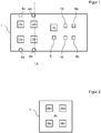
- FIG. 1 A basic unit 1 of a first exemplary embodiment of a device according to the invention for detecting mold infestation is shown in a top view from above.
- the basic unit has four optical detectors 2a, 2b, 2c and 2d.
- Each optical detector is designed as an RGB color sensor.
- the basic unit 1 also has an evaluation unit 3. This is designed as a simple computer unit, with a computing processor and a memory unit, in particular for an evaluation program.
- the basic unit 1 also has two illuminants: a green LED 4a and a red LED 4b.
- the evaluation unit 3 is connected to the optical detectors 2a to 2d in order to trigger their measured values. Furthermore, the evaluation unit 3 is connected to the lamps 4a and 4b in order to display a result of the evaluation by means of the lamps.
- the basic unit 1 also has an energy source 5 designed as a battery, which is connected to the evaluation unit for energy supply.
- the base unit 1 has four detents 6a, 6b, 6c and 6d in order to arrange a detection unit by means of the detents on the base unit 1 above the optical detectors 2a to 2d:
- a detection unit 7 of the first exemplary embodiment is shown in a top view from above.
- the detection unit 7 has a transparent optical carrier 8, which is formed from glass. There are four on the optical carrier 8
- Detection areas 9a, 9b, 9c and 9d are formed, in each of which the following sensitive dyes are embedded in a polymer as carrier matrix: Detection range sensitive dye detected parameters
- Metal oxides e.g. Cr (VI) oxide
- Each of these dyes can thus change its color depending on the target gas concentration of the target gas specified in the table or the pH value.
- the detection unit 7 is designed as a disposable label and can therefore be replaced after the measurement has taken place.
- the basic unit 1, on the other hand, is reused with the new disposable label.
- the detection unit 7 is arranged on the base unit 1 by means of the latching lugs 6a-6d by the detection unit 7 being clipped in or pushed in.
- Figure 3 is a section along the line A in Figure 1 and perpendicular to the plane of the drawing in Figure 1 shown with the detection unit 7 arranged on the base unit 1.
- the detection areas 9b and 9d are respectively arranged above the optical detectors 2b and 2d.
- the detection areas 9a and 9c are arranged above the optical detectors 2a and 2c.
- the optical detectors 2a to 2d each have micro-optics with converging lenses on the side facing the detection unit 7. Examples are in Figure 3 the micro-optics 2d 'of the optical detector 2d and 2b' of the optical detector 2b are shown.
- the measurement signals of the optical detectors 2a to 2d are read out by the evaluation unit 3 and evaluated with regard to a color change.
- the evaluation begins as soon as an energy source 5, in the present case a battery, is inserted into the basic unit 1.
- a start button is provided for starting the evaluation.
- an infestation of mold is detected if at least two of the detection areas respond.
- the red LED 4b in the case of mold infestation and the green LED 4a in the case of undetected mold infestation are illuminated by means of the evaluation unit 3.
- the basic unit 1 additionally has a moisture sensor 10 and a temperature sensor 11, which are likewise connected to the evaluation unit 3.
- the evaluation unit not only measures any color changes in the detection areas 9a to 9d, but also additionally a humidity value using the humidity sensor 10 and a temperature value using the temperature sensor 11.
- FIG 4 the basic unit of a second embodiment of a device according to the invention is shown.
- the basic unit assigns the same structure as that except for a few changes Figure 1 described first embodiment. To avoid repetition, only the main differences are discussed below:
- the basic unit of the second exemplary embodiment has only one optical detector 2e.
- the optical detector 2e has a large detection area which comprises the entire area which is covered by the detection areas of the optical detectors 2a to 2d of the first exemplary embodiment.
- the basic unit of the second exemplary embodiment is also for use with a detection unit 7 according to Figure 2 educated.
- the detection unit 7 is arranged on the base unit 1 by means of the detents 6a to 6d, the detection areas 9a to 9d are all located over the large-area detection area of the optical detector 2e, so that light passing through the detection areas 9a to 9d strikes the optical detector 2e .
- the optical detector 2e is designed as a spectrally resolving RGB sensor.
- the detection areas 9a to 9d are designed such that a color change takes place in different spectral areas.
- the optical detector 2e as a spectrally resolving detector, a color change can thus be determined separately for each detection range 9a to 9d based on the measurement data of the sensor, since a change in the spectrum can be assigned to the respective spectral range of the detection range due to the spectral resolution.
Landscapes
- Chemical & Material Sciences (AREA)
- Life Sciences & Earth Sciences (AREA)
- Health & Medical Sciences (AREA)
- Physics & Mathematics (AREA)
- Pathology (AREA)
- Analytical Chemistry (AREA)
- Biochemistry (AREA)
- General Health & Medical Sciences (AREA)
- General Physics & Mathematics (AREA)
- Immunology (AREA)
- Plasma & Fusion (AREA)
- Chemical Kinetics & Catalysis (AREA)
- Engineering & Computer Science (AREA)
- Dispersion Chemistry (AREA)
- Biophysics (AREA)
- Molecular Biology (AREA)
- Investigating Or Analysing Materials By The Use Of Chemical Reactions (AREA)
Priority Applications (1)
| Application Number | Priority Date | Filing Date | Title |
|---|---|---|---|
| EP18207976.4A EP3657164A1 (fr) | 2018-11-23 | 2018-11-23 | Dispositif et procédé de détection de formation de moisissure |
Applications Claiming Priority (1)
| Application Number | Priority Date | Filing Date | Title |
|---|---|---|---|
| EP18207976.4A EP3657164A1 (fr) | 2018-11-23 | 2018-11-23 | Dispositif et procédé de détection de formation de moisissure |
Publications (1)
| Publication Number | Publication Date |
|---|---|
| EP3657164A1 true EP3657164A1 (fr) | 2020-05-27 |
Family
ID=64559439
Family Applications (1)
| Application Number | Title | Priority Date | Filing Date |
|---|---|---|---|
| EP18207976.4A Withdrawn EP3657164A1 (fr) | 2018-11-23 | 2018-11-23 | Dispositif et procédé de détection de formation de moisissure |
Country Status (1)
| Country | Link |
|---|---|
| EP (1) | EP3657164A1 (fr) |
Citations (7)
| Publication number | Priority date | Publication date | Assignee | Title |
|---|---|---|---|---|
| US20030164024A1 (en) * | 2002-03-04 | 2003-09-04 | Rikei Corporation | Biosensor and method for production thereof |
| EP1574836A1 (fr) | 2004-03-12 | 2005-09-14 | Gerhard Dr. Führer | Procédé et kit d'essai pour detection de substances nocives à l'air interieur |
| US20100238035A1 (en) * | 2009-03-19 | 2010-09-23 | Tangidyne Corporation | Detection device and method for detecting analyte |
| EP2610617A1 (fr) | 2011-12-28 | 2013-07-03 | Centre Scientifique et Technique du Batiment | Dispositif et procédé de détection d'une contamination fongique dans un environnement intérieur |
| US20150168307A1 (en) * | 2012-07-20 | 2015-06-18 | Drager Safety AG & Co. KGaA a corporation | Gas measurement system |
| DE102016107158A1 (de) * | 2016-04-18 | 2017-10-19 | Fraunhofer-Gesellschaft zur Förderung der angewandten Forschung e.V. | Gassensor und Verfahren zur Herstellung einer gassensitiven Schicht für einen optischen Gassensor |
| US20180231513A1 (en) * | 2017-02-16 | 2018-08-16 | iSense LLC | Sensor arrays with nucleophilic indicators |
-
2018
- 2018-11-23 EP EP18207976.4A patent/EP3657164A1/fr not_active Withdrawn
Patent Citations (7)
| Publication number | Priority date | Publication date | Assignee | Title |
|---|---|---|---|---|
| US20030164024A1 (en) * | 2002-03-04 | 2003-09-04 | Rikei Corporation | Biosensor and method for production thereof |
| EP1574836A1 (fr) | 2004-03-12 | 2005-09-14 | Gerhard Dr. Führer | Procédé et kit d'essai pour detection de substances nocives à l'air interieur |
| US20100238035A1 (en) * | 2009-03-19 | 2010-09-23 | Tangidyne Corporation | Detection device and method for detecting analyte |
| EP2610617A1 (fr) | 2011-12-28 | 2013-07-03 | Centre Scientifique et Technique du Batiment | Dispositif et procédé de détection d'une contamination fongique dans un environnement intérieur |
| US20150168307A1 (en) * | 2012-07-20 | 2015-06-18 | Drager Safety AG & Co. KGaA a corporation | Gas measurement system |
| DE102016107158A1 (de) * | 2016-04-18 | 2017-10-19 | Fraunhofer-Gesellschaft zur Förderung der angewandten Forschung e.V. | Gassensor und Verfahren zur Herstellung einer gassensitiven Schicht für einen optischen Gassensor |
| US20180231513A1 (en) * | 2017-02-16 | 2018-08-16 | iSense LLC | Sensor arrays with nucleophilic indicators |
Similar Documents
| Publication | Publication Date | Title |
|---|---|---|
| DE10008517C2 (de) | Optisches Meßsystem | |
| DE2902776C2 (fr) | ||
| DE19544501A1 (de) | Vorrichtung für Lichtreflexionsmessungen | |
| WO2004070329A2 (fr) | Spectrometre compact | |
| EP0343143A2 (fr) | Procédé et appareil pour mesurer le lambda et/ou le rapport air/carburant | |
| DE2124242A1 (de) | Photoelektrisches Kolonmeter | |
| DE102009028254A1 (de) | Verfahren für Untersuchungen an Flüssigkeiten sowie Vorrichtung hierfür | |
| DE2324049B2 (de) | Geraet zur photoelektrischen analyse | |
| DE102011055272A1 (de) | Verfahren zur Bestimmung eines relaxationszeitabhängigen Parameters zu einem System | |
| DE102010046829A1 (de) | Verfahren zur Bestimmung von Gaskonzentrationen in einem Gasgemisch basierend auf Wärmeleitfähigkeitsmessungen mit Messwertkorrektur | |
| DE102011050969A1 (de) | Vorrichtung zur referenzierten Messung von reflektiertem Licht und Verfahren zum Kalibrieren einer solchen Vorrichtung | |
| DE10148750B4 (de) | Vorrichtung und Verfahren zur Detektion von Schimmelpilzbefall auf einer Oberfläche | |
| DE102012107319B4 (de) | Passives Messsystem | |
| EP2658957B1 (fr) | Appareil de mesure portatif pour identifier la présence d'attaques de moisissures non apparentes | |
| WO2002035181A1 (fr) | Dispositif pour verifier et controler une vitre en verre simple, un element en verre isolant ou un verre feuillete | |
| EP0193036B1 (fr) | Utilisation d'un filtre optique à changement de couleur réversible | |
| EP3657164A1 (fr) | Dispositif et procédé de détection de formation de moisissure | |
| EP0193037B1 (fr) | Utilisation d'un elément de construction chimiquement sensible | |
| DE102012108620A1 (de) | Verfahren zum Bestimmen der Weglänge einer Probe und Validierung der damit erhaltenen Messung | |
| DE102015222769A1 (de) | Verfahren zum Abgleichen eines optischen Fluidsensors | |
| EP3911927B1 (fr) | Système de spectromètre et procédé de contrôle de celui-ci | |
| DE202017106043U1 (de) | Feuchtedetektor zur Erkennung von flüssigem Wasser auf einer zu untersuchenden Oberfläche | |
| DE102006055095B3 (de) | Luftfeuchtigkeitsmessvorrichtung und Verfahren zur Kondensationsfeuchtigkeitsermittlung | |
| DE19714903A1 (de) | Verfahren zur Kalibrierung von NDIR-Spektrometern | |
| DE102005036616A1 (de) | Irreversibler passiver Gassensor |
Legal Events
| Date | Code | Title | Description |
|---|---|---|---|
| PUAI | Public reference made under article 153(3) epc to a published international application that has entered the european phase |
Free format text: ORIGINAL CODE: 0009012 |
|
| STAA | Information on the status of an ep patent application or granted ep patent |
Free format text: STATUS: REQUEST FOR EXAMINATION WAS MADE |
|
| 17P | Request for examination filed |
Effective date: 20191227 |
|
| AK | Designated contracting states |
Kind code of ref document: A1 Designated state(s): AL AT BE BG CH CY CZ DE DK EE ES FI FR GB GR HR HU IE IS IT LI LT LU LV MC MK MT NL NO PL PT RO RS SE SI SK SM TR |
|
| AX | Request for extension of the european patent |
Extension state: BA ME |
|
| STAA | Information on the status of an ep patent application or granted ep patent |
Free format text: STATUS: EXAMINATION IS IN PROGRESS |
|
| 17Q | First examination report despatched |
Effective date: 20201007 |
|
| STAA | Information on the status of an ep patent application or granted ep patent |
Free format text: STATUS: THE APPLICATION IS DEEMED TO BE WITHDRAWN |
|
| 18D | Application deemed to be withdrawn |
Effective date: 20210420 |