EP3657202A2 - Système de guidage à base de radar à onde mm et procédés l'utilisant - Google Patents
Système de guidage à base de radar à onde mm et procédés l'utilisant Download PDFInfo
- Publication number
- EP3657202A2 EP3657202A2 EP19211315.7A EP19211315A EP3657202A2 EP 3657202 A2 EP3657202 A2 EP 3657202A2 EP 19211315 A EP19211315 A EP 19211315A EP 3657202 A2 EP3657202 A2 EP 3657202A2
- Authority
- EP
- European Patent Office
- Prior art keywords
- operation step
- executed
- apparatuses
- vehicle
- declared
- Prior art date
- Legal status (The legal status is an assumption and is not a legal conclusion. Google has not performed a legal analysis and makes no representation as to the accuracy of the status listed.)
- Pending
Links
Images



Classifications
-
- G—PHYSICS
- G01—MEASURING; TESTING
- G01S—RADIO DIRECTION-FINDING; RADIO NAVIGATION; DETERMINING DISTANCE OR VELOCITY BY USE OF RADIO WAVES; LOCATING OR PRESENCE-DETECTING BY USE OF THE REFLECTION OR RERADIATION OF RADIO WAVES; ANALOGOUS ARRANGEMENTS USING OTHER WAVES
- G01S13/00—Systems using the reflection or reradiation of radio waves, e.g. radar systems; Analogous systems using reflection or reradiation of waves whose nature or wavelength is irrelevant or unspecified
- G01S13/87—Combinations of radar systems, e.g. primary radar and secondary radar
- G01S13/876—Combination of several spaced transponders or reflectors of known location for determining the position of a receiver
-
- G—PHYSICS
- G01—MEASURING; TESTING
- G01S—RADIO DIRECTION-FINDING; RADIO NAVIGATION; DETERMINING DISTANCE OR VELOCITY BY USE OF RADIO WAVES; LOCATING OR PRESENCE-DETECTING BY USE OF THE REFLECTION OR RERADIATION OF RADIO WAVES; ANALOGOUS ARRANGEMENTS USING OTHER WAVES
- G01S13/00—Systems using the reflection or reradiation of radio waves, e.g. radar systems; Analogous systems using reflection or reradiation of waves whose nature or wavelength is irrelevant or unspecified
- G01S13/74—Systems using reradiation of radio waves, e.g. secondary radar systems; Analogous systems
- G01S13/75—Systems using reradiation of radio waves, e.g. secondary radar systems; Analogous systems using transponders powered from received waves, e.g. using passive transponders, or using passive reflectors
-
- G—PHYSICS
- G01—MEASURING; TESTING
- G01S—RADIO DIRECTION-FINDING; RADIO NAVIGATION; DETERMINING DISTANCE OR VELOCITY BY USE OF RADIO WAVES; LOCATING OR PRESENCE-DETECTING BY USE OF THE REFLECTION OR RERADIATION OF RADIO WAVES; ANALOGOUS ARRANGEMENTS USING OTHER WAVES
- G01S13/00—Systems using the reflection or reradiation of radio waves, e.g. radar systems; Analogous systems using reflection or reradiation of waves whose nature or wavelength is irrelevant or unspecified
- G01S13/88—Radar or analogous systems specially adapted for specific applications
- G01S13/93—Radar or analogous systems specially adapted for specific applications for anti-collision purposes
- G01S13/931—Radar or analogous systems specially adapted for specific applications for anti-collision purposes of land vehicles
-
- G—PHYSICS
- G01—MEASURING; TESTING
- G01S—RADIO DIRECTION-FINDING; RADIO NAVIGATION; DETERMINING DISTANCE OR VELOCITY BY USE OF RADIO WAVES; LOCATING OR PRESENCE-DETECTING BY USE OF THE REFLECTION OR RERADIATION OF RADIO WAVES; ANALOGOUS ARRANGEMENTS USING OTHER WAVES
- G01S7/00—Details of systems according to groups G01S13/00, G01S15/00, G01S17/00
- G01S7/02—Details of systems according to groups G01S13/00, G01S15/00, G01S17/00 of systems according to group G01S13/00
- G01S7/024—Details of systems according to groups G01S13/00, G01S15/00, G01S17/00 of systems according to group G01S13/00 using polarisation effects
-
- G—PHYSICS
- G01—MEASURING; TESTING
- G01S—RADIO DIRECTION-FINDING; RADIO NAVIGATION; DETERMINING DISTANCE OR VELOCITY BY USE OF RADIO WAVES; LOCATING OR PRESENCE-DETECTING BY USE OF THE REFLECTION OR RERADIATION OF RADIO WAVES; ANALOGOUS ARRANGEMENTS USING OTHER WAVES
- G01S7/00—Details of systems according to groups G01S13/00, G01S15/00, G01S17/00
- G01S7/02—Details of systems according to groups G01S13/00, G01S15/00, G01S17/00 of systems according to group G01S13/00
- G01S7/03—Details of HF subsystems specially adapted therefor, e.g. common to transmitter and receiver
- G01S7/032—Constructional details for solid-state radar subsystems
-
- G—PHYSICS
- G01—MEASURING; TESTING
- G01S—RADIO DIRECTION-FINDING; RADIO NAVIGATION; DETERMINING DISTANCE OR VELOCITY BY USE OF RADIO WAVES; LOCATING OR PRESENCE-DETECTING BY USE OF THE REFLECTION OR RERADIATION OF RADIO WAVES; ANALOGOUS ARRANGEMENTS USING OTHER WAVES
- G01S7/00—Details of systems according to groups G01S13/00, G01S15/00, G01S17/00
- G01S7/02—Details of systems according to groups G01S13/00, G01S15/00, G01S17/00 of systems according to group G01S13/00
- G01S7/41—Details of systems according to groups G01S13/00, G01S15/00, G01S17/00 of systems according to group G01S13/00 using analysis of echo signal for target characterisation; Target signature; Target cross-section
- G01S7/411—Identification of targets based on measurements of radar reflectivity
-
- G—PHYSICS
- G01—MEASURING; TESTING
- G01S—RADIO DIRECTION-FINDING; RADIO NAVIGATION; DETERMINING DISTANCE OR VELOCITY BY USE OF RADIO WAVES; LOCATING OR PRESENCE-DETECTING BY USE OF THE REFLECTION OR RERADIATION OF RADIO WAVES; ANALOGOUS ARRANGEMENTS USING OTHER WAVES
- G01S7/00—Details of systems according to groups G01S13/00, G01S15/00, G01S17/00
- G01S7/02—Details of systems according to groups G01S13/00, G01S15/00, G01S17/00 of systems according to group G01S13/00
- G01S7/41—Details of systems according to groups G01S13/00, G01S15/00, G01S17/00 of systems according to group G01S13/00 using analysis of echo signal for target characterisation; Target signature; Target cross-section
- G01S7/415—Identification of targets based on measurements of movement associated with the target
-
- G—PHYSICS
- G05—CONTROLLING; REGULATING
- G05D—SYSTEMS FOR CONTROLLING OR REGULATING NON-ELECTRIC VARIABLES
- G05D1/00—Control of position, course, altitude or attitude of land, water, air or space vehicles, e.g. using automatic pilots
- G05D1/02—Control of position or course in two dimensions
- G05D1/021—Control of position or course in two dimensions specially adapted to land vehicles
- G05D1/0212—Control of position or course in two dimensions specially adapted to land vehicles with means for defining a desired trajectory
-
- G—PHYSICS
- G05—CONTROLLING; REGULATING
- G05D—SYSTEMS FOR CONTROLLING OR REGULATING NON-ELECTRIC VARIABLES
- G05D1/00—Control of position, course, altitude or attitude of land, water, air or space vehicles, e.g. using automatic pilots
- G05D1/02—Control of position or course in two dimensions
- G05D1/021—Control of position or course in two dimensions specially adapted to land vehicles
- G05D1/0257—Control of position or course in two dimensions specially adapted to land vehicles using a radar
-
- H—ELECTRICITY
- H01—ELECTRIC ELEMENTS
- H01Q—ANTENNAS, i.e. RADIO AERIALS
- H01Q1/00—Details of, or arrangements associated with, antennas
- H01Q1/27—Adaptation for use in or on movable bodies
- H01Q1/32—Adaptation for use in or on road or rail vehicles
- H01Q1/3208—Adaptation for use in or on road or rail vehicles characterised by the application wherein the antenna is used
- H01Q1/3233—Adaptation for use in or on road or rail vehicles characterised by the application wherein the antenna is used particular used as part of a sensor or in a security system, e.g. for automotive radar, navigation systems
-
- H—ELECTRICITY
- H01—ELECTRIC ELEMENTS
- H01Q—ANTENNAS, i.e. RADIO AERIALS
- H01Q21/00—Antenna arrays or systems
- H01Q21/06—Arrays of individually energised antenna units similarly polarised and spaced apart
- H01Q21/061—Two dimensional planar arrays
- H01Q21/065—Patch antenna array
-
- G—PHYSICS
- G01—MEASURING; TESTING
- G01S—RADIO DIRECTION-FINDING; RADIO NAVIGATION; DETERMINING DISTANCE OR VELOCITY BY USE OF RADIO WAVES; LOCATING OR PRESENCE-DETECTING BY USE OF THE REFLECTION OR RERADIATION OF RADIO WAVES; ANALOGOUS ARRANGEMENTS USING OTHER WAVES
- G01S13/00—Systems using the reflection or reradiation of radio waves, e.g. radar systems; Analogous systems using reflection or reradiation of waves whose nature or wavelength is irrelevant or unspecified
- G01S13/02—Systems using reflection of radio waves, e.g. primary radar systems; Analogous systems
- G01S13/06—Systems determining position data of a target
- G01S13/42—Simultaneous measurement of distance and other co-ordinates
-
- G—PHYSICS
- G01—MEASURING; TESTING
- G01S—RADIO DIRECTION-FINDING; RADIO NAVIGATION; DETERMINING DISTANCE OR VELOCITY BY USE OF RADIO WAVES; LOCATING OR PRESENCE-DETECTING BY USE OF THE REFLECTION OR RERADIATION OF RADIO WAVES; ANALOGOUS ARRANGEMENTS USING OTHER WAVES
- G01S13/00—Systems using the reflection or reradiation of radio waves, e.g. radar systems; Analogous systems using reflection or reradiation of waves whose nature or wavelength is irrelevant or unspecified
- G01S13/87—Combinations of radar systems, e.g. primary radar and secondary radar
- G01S13/874—Combination of several systems for attitude determination
-
- G—PHYSICS
- G01—MEASURING; TESTING
- G01S—RADIO DIRECTION-FINDING; RADIO NAVIGATION; DETERMINING DISTANCE OR VELOCITY BY USE OF RADIO WAVES; LOCATING OR PRESENCE-DETECTING BY USE OF THE REFLECTION OR RERADIATION OF RADIO WAVES; ANALOGOUS ARRANGEMENTS USING OTHER WAVES
- G01S13/00—Systems using the reflection or reradiation of radio waves, e.g. radar systems; Analogous systems using reflection or reradiation of waves whose nature or wavelength is irrelevant or unspecified
- G01S13/88—Radar or analogous systems specially adapted for specific applications
- G01S13/93—Radar or analogous systems specially adapted for specific applications for anti-collision purposes
- G01S13/931—Radar or analogous systems specially adapted for specific applications for anti-collision purposes of land vehicles
- G01S2013/9314—Parking operations
-
- G—PHYSICS
- G01—MEASURING; TESTING
- G01S—RADIO DIRECTION-FINDING; RADIO NAVIGATION; DETERMINING DISTANCE OR VELOCITY BY USE OF RADIO WAVES; LOCATING OR PRESENCE-DETECTING BY USE OF THE REFLECTION OR RERADIATION OF RADIO WAVES; ANALOGOUS ARRANGEMENTS USING OTHER WAVES
- G01S13/00—Systems using the reflection or reradiation of radio waves, e.g. radar systems; Analogous systems using reflection or reradiation of waves whose nature or wavelength is irrelevant or unspecified
- G01S13/88—Radar or analogous systems specially adapted for specific applications
- G01S13/93—Radar or analogous systems specially adapted for specific applications for anti-collision purposes
- G01S13/931—Radar or analogous systems specially adapted for specific applications for anti-collision purposes of land vehicles
- G01S2013/9315—Monitoring blind spots
-
- G—PHYSICS
- G01—MEASURING; TESTING
- G01S—RADIO DIRECTION-FINDING; RADIO NAVIGATION; DETERMINING DISTANCE OR VELOCITY BY USE OF RADIO WAVES; LOCATING OR PRESENCE-DETECTING BY USE OF THE REFLECTION OR RERADIATION OF RADIO WAVES; ANALOGOUS ARRANGEMENTS USING OTHER WAVES
- G01S13/00—Systems using the reflection or reradiation of radio waves, e.g. radar systems; Analogous systems using reflection or reradiation of waves whose nature or wavelength is irrelevant or unspecified
- G01S13/88—Radar or analogous systems specially adapted for specific applications
- G01S13/93—Radar or analogous systems specially adapted for specific applications for anti-collision purposes
- G01S13/931—Radar or analogous systems specially adapted for specific applications for anti-collision purposes of land vehicles
- G01S2013/9318—Controlling the steering
-
- G—PHYSICS
- G01—MEASURING; TESTING
- G01S—RADIO DIRECTION-FINDING; RADIO NAVIGATION; DETERMINING DISTANCE OR VELOCITY BY USE OF RADIO WAVES; LOCATING OR PRESENCE-DETECTING BY USE OF THE REFLECTION OR RERADIATION OF RADIO WAVES; ANALOGOUS ARRANGEMENTS USING OTHER WAVES
- G01S13/00—Systems using the reflection or reradiation of radio waves, e.g. radar systems; Analogous systems using reflection or reradiation of waves whose nature or wavelength is irrelevant or unspecified
- G01S13/88—Radar or analogous systems specially adapted for specific applications
- G01S13/93—Radar or analogous systems specially adapted for specific applications for anti-collision purposes
- G01S13/931—Radar or analogous systems specially adapted for specific applications for anti-collision purposes of land vehicles
- G01S2013/9327—Sensor installation details
- G01S2013/93275—Sensor installation details in the bumper area
-
- G—PHYSICS
- G01—MEASURING; TESTING
- G01S—RADIO DIRECTION-FINDING; RADIO NAVIGATION; DETERMINING DISTANCE OR VELOCITY BY USE OF RADIO WAVES; LOCATING OR PRESENCE-DETECTING BY USE OF THE REFLECTION OR RERADIATION OF RADIO WAVES; ANALOGOUS ARRANGEMENTS USING OTHER WAVES
- G01S13/00—Systems using the reflection or reradiation of radio waves, e.g. radar systems; Analogous systems using reflection or reradiation of waves whose nature or wavelength is irrelevant or unspecified
- G01S13/88—Radar or analogous systems specially adapted for specific applications
- G01S13/93—Radar or analogous systems specially adapted for specific applications for anti-collision purposes
- G01S13/931—Radar or analogous systems specially adapted for specific applications for anti-collision purposes of land vehicles
- G01S2013/9329—Radar or analogous systems specially adapted for specific applications for anti-collision purposes of land vehicles cooperating with reflectors or transponders
-
- G—PHYSICS
- G01—MEASURING; TESTING
- G01S—RADIO DIRECTION-FINDING; RADIO NAVIGATION; DETERMINING DISTANCE OR VELOCITY BY USE OF RADIO WAVES; LOCATING OR PRESENCE-DETECTING BY USE OF THE REFLECTION OR RERADIATION OF RADIO WAVES; ANALOGOUS ARRANGEMENTS USING OTHER WAVES
- G01S7/00—Details of systems according to groups G01S13/00, G01S15/00, G01S17/00
- G01S7/02—Details of systems according to groups G01S13/00, G01S15/00, G01S17/00 of systems according to group G01S13/00
- G01S7/03—Details of HF subsystems specially adapted therefor, e.g. common to transmitter and receiver
-
- G—PHYSICS
- G01—MEASURING; TESTING
- G01S—RADIO DIRECTION-FINDING; RADIO NAVIGATION; DETERMINING DISTANCE OR VELOCITY BY USE OF RADIO WAVES; LOCATING OR PRESENCE-DETECTING BY USE OF THE REFLECTION OR RERADIATION OF RADIO WAVES; ANALOGOUS ARRANGEMENTS USING OTHER WAVES
- G01S7/00—Details of systems according to groups G01S13/00, G01S15/00, G01S17/00
- G01S7/02—Details of systems according to groups G01S13/00, G01S15/00, G01S17/00 of systems according to group G01S13/00
- G01S7/35—Details of non-pulse systems
- G01S7/352—Receivers
- G01S7/358—Receivers using I/Q processing
-
- G—PHYSICS
- G01—MEASURING; TESTING
- G01S—RADIO DIRECTION-FINDING; RADIO NAVIGATION; DETERMINING DISTANCE OR VELOCITY BY USE OF RADIO WAVES; LOCATING OR PRESENCE-DETECTING BY USE OF THE REFLECTION OR RERADIATION OF RADIO WAVES; ANALOGOUS ARRANGEMENTS USING OTHER WAVES
- G01S7/00—Details of systems according to groups G01S13/00, G01S15/00, G01S17/00
- G01S7/02—Details of systems according to groups G01S13/00, G01S15/00, G01S17/00 of systems according to group G01S13/00
- G01S7/41—Details of systems according to groups G01S13/00, G01S15/00, G01S17/00 of systems according to group G01S13/00 using analysis of echo signal for target characterisation; Target signature; Target cross-section
- G01S7/417—Details of systems according to groups G01S13/00, G01S15/00, G01S17/00 of systems according to group G01S13/00 using analysis of echo signal for target characterisation; Target signature; Target cross-section involving the use of neural networks
Definitions
- MM-wave radar sensor system described by apparatuses and method of operation for 3D object position detection, shape detection, smart autonomous driving in the pre-defined and marked areas and for authentication applications is introduced.
- the present invention relates to a sensor system and method of operation addressing set of applications: 3D object orientation and position of the known object, shape detection and selection of the known object classes, authentication and recognition of the classes of objects and classes of person as well as autonomous driving and parking in the pre-defined and known areas.
- MM-wave radar sensor system with its method of operation is introduced, using mm-wave radio frequencies.
- the specific problems or known objects is addressed, where the sensor is on the 3D grades of freedom moving platform or objects is known and stable, and where the sensor is in stable position and objects is on 3D grades of freedom moving platform.
- the third class of addressed application by the proposed sensor system and its method of operation is recognising of the marked and known object if it is alone, or recognising the marked object within other non-marked objects, where in all three classes of application, the object can also be a live being having cloths which is marked by the approach, being described in this invention.
- Application scenario c) may be explicitly favourable increasing safety when video recognition-based auto pilots are not functioning, or not functioning in the full capacity, as in case of smoke, fog or very dense direct light.
- d) Detection if the seat is occupied and if the safety belt is locked, without need to have a power supply in the seat environment.
- State of art solutions are utilising power supply in the seats for safety belt locking, or sensor fusion radar plus video detecting safety belt.
- the object is known, and the generalized object can be arbitrary non-live object, or live being having clothes or marked attached environment close to its surface. In the process of the decision the machine learning procedures may apply.
- the state of art solutions are covering wireless systems, where the reflectors are reflecting the radio waves being send to them.
- the most popular such system are RFID systems, where RFID passive reflectors are without power, but they are using the energy being sent by RFID transmitter and they are making their identification, by sending their code, meaning that each reflector has unique identification, and RFID reader has a concept to read out those identification codes.
- RFID systems where RFID passive reflectors are without power, but they are using the energy being sent by RFID transmitter and they are making their identification, by sending their code, meaning that each reflector has unique identification, and RFID reader has a concept to read out those identification codes.
- the system of the radar sensor being used as normal radar sensor for measuring distances, speed and vibrations as a part of the system, where the fully passive reflector, without own reflector code identification, at least one, and preferably more than one fully identical, are used.
- the special arrangement of the identical passive reflectors are determining the 3D position of the known object, its shape and possible its identification, related to the classes of the same object, and not for identification of the objects being in the same class. This approach allows very low-cost deployment of the proposed system solution.
- the following set of the patent applications and granted patents as well as assotiated selected publications are describing the state of art in the field.
- a locationing system for use in a wireless network generally includes a wireless switch and a global positioning system (GPS) with RFID Network.
- GPS global positioning system
- At least one RFID reader (mobile and/or fixed) is configured to communicate with the access port, and the RFID reader is configured to read an RFID tag and communicate RFID tag data to the wireless switch.
- RFID reader is sending data and receiving ID from the RFID transponder, taking power from the emitter RF signal strength.
- the present invention relates to reflector arrangement for proof test of a radar level gauge and to a radar level gauge system comprising such a reflector arrangement, for automotive tank application.
- US8350752B2 "Radar level gauge system with bottom ..” introduces a radar level gauge system, for determining a filling level of a product contained in a tank, the radar level gauge system comprising: a transceiver for generating, transmitting and receiving electromagnetic signals; a propagating device electrically connected to the transceiver and arranged to propagate a transmitted electromagnetic signal towards a surface of the product contained in the ...
- US5387916 "Automotive Navigation system and Method” introduces the responder uses a Van Atta array antenna, using for navigation enhancement.
- the responder includes encoding means coupled to the receiving antenna means for imposing automotive navigation information on the collected interrogation signal, the responder including retrodirective means connected to the encoding means for retransmitting the encoding collected interrogation signal.
- This interrogator send coded signal by intention, addressing a vehicle travelling along a highway and it is not a part of the classing radar based distance collection systems.
- Retro-reflectors which are often passive, may contain active elements which may be included to enhance the backscattered signal, or to modify it in some way, such as by the introduction of modulation may happen for the identification purposes.
- This invention proposes a system having apparatus part 100 and apparatus part 2000, as well as the method of operation, being able:
- the features of the proposed system address objects also as human beings having marked cloths, in its generalised meaning.
- Apparatus 100 is radar system having at least one transmitter and two receiver chains with high gain antennas, being connected to the vehicle infrastructure 1000, and being realised by the arbitrary technology solutions.
- the apparatus 2000 is passive system with the arbitrary realisation options, where passive means that the apparatus 2000 does not have power supply, where the apparatus 2000 has a feature that the incident radio waves to the apparatus receiving surface are reflected by approaching apparatus 2000 in the same angle as received.
- apparatus 2000 can reflected the waves in the same polarisation as received or in orthogonal radio waves polarization.
- different apparatus 2000 realization options are outlined, being realized by metalized corner reflectors, or printed planar structures, without and with changing of the incident radio waves polarisation.
- the total reflected energy to the radar systems is dependent on the level of the scattered waves in other directions as the direction of the incident waves. Due to the fact, that if the radar is receiving antennas and on the same place where transmit antennas are, the receiving power level from specific reflections is dependent of the level of scattering waves. If the object, would have features to reduce parasitic scattering and would reflect more power in the directions, where it is illuminated, its effective radar cross section would be larger, and receiving antenna at the radar will register more receiving power. With other words object having features for having less parasitic scattering and better reflection of the illuminated radio power to the direction of the illumination is better visible in the radar signal processing, compared to the environment in its enclosure without this feature. Even if the environment has metalized surfaces, the visibility of is larger, if waves may be reflected in the same way where the illumination of the signal is presented.
- the innovative proposed system would have ability to detect rotation and position in contrast to state of art radar systems, calculating distance with radar cross section classifications.
- reflectors for increasing radar cross sections are used to increase the visibility of the objects by long range radar observation, like better visibility of the floating and sailing objects on the see.
- proposed markers with better reflection are inertially use to detect orientation of the know object, rather to distance. They are also use for the purpose of detecting object shapes and object classification within different classes of marked objects.
- the important advantage of the proposed system and method of operation is that the proposed system allows recognising the objects, its position or classification, also in the case where the object is reflecting waves strongly, being made from metalized structures or having in its enclosure and environment a lot of metalized structures.
- the key system-relevant components of the proposed apparatus 100 are:
- the choice to use the mm-wave frequency band (30 GHz to 300 GHz) and advantageously to use non-licenced 60 GHz band, ISM 60 GHz Band and 79 GHz Automotive band, is mainly related to the size of the antenna system allowing very small and compact device, even though it contains the high-gain antenna with more than one radiation elements. Usage of higher frequencies enables to have on predefined object more apparatuses 2000, where their radiation size is minimum 10 X 10 wavelengths under operation, for the practical realization purposes and for enhanced reflectiveness. Due to mm-wave frequencies in the practical applications advantageously more than one apparatus 2000 are utilized.
- mm-Wave System comprising the one apparatus 100 with mm-wave HW radar functionality, and at least two apparatuses 2000 being is placed physically at the distance from apparatus 100, where mm-wave declares operation between 30 and 300 GHz like in Fig 1 .
- Apparatus 100 contains:
- At least two apparatuses 2000 are attached to the known and pre-defined object 300.
- the Method of operation related to the Fig. 1 contains three steps, where the first operation step has following sub-set of operations:
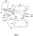
- FIG. 2 application scenario related to the autonomous driving in the pre-defined area like parking spaces and garages are described.
- the vehicle 301 is entering parking area and has apparatus 100 on the board looking in the direction of the vehicle movement.
- the apparatus 100 detect the existence of the passive apparatuses 2000.
- the apparatus 100 is detecting angular positions and distances to the passive apparatuses 3002 and 300, and the vehicle autopilot is calculating the trajectory 2001, so that the vehicle 3001 is autonomous or manually driven by driver with warning assistance from the markers calculate or take, respectively trajectory 2001 being in the middle between the apparatuses 3001 and 3002.
- the vehicle system knows which specific parking space is entered, and the vehicle navigation system has this information, including the distances between the apparatuses 2000 and their positions in the parking and moving area.
- the vehicle 301 is moving between the parked cars 302 and 303 they are approaching apparatuses 3003 and 3004 being attached to the wall. Having their positions being calculated by apparatus 100, the vehicle 301 can park exactly in the middle of the parking space and at exact prefer distance to the wall.
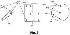
- Fig. 3 describes the third application scenario being related to the detection of the class of the pre-defined and known objects.
- Those classes of the object are for example denoted as 304, 305, 306 and may have other outlooks like class of simply quadratic type of shapes. For example, if we have a harbour and crane looking from the top to the down, the crane will see different type of the objects. If these objects are marked by the attachment of the apparatuses 2000, the crane having apparatus 100 looking top to the down, will recognized shapes below the carne, and make take different type of actions, like move one shape by detecting it from one place to another.
- the crane may align its picking precision very preciously due to the attached 4 group of markers to pick up the container in the proper ways, autonomously.
- the known object 306 which may be a cylinder.
- the apparatuses 2000 and their detection we may also combine the shape detection with the orientation of the object to the crane. In this particular case we may see if the cylinder are rotated and with which angle.
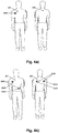
- Fig 4 show application scenario, where proposed passive apparatuses 2000 or a group of apparatuses 2000 are integrated in the clothing of the people intentionally. Having apparatuses being integrated in the cloths, will increase the radar cross section, or in other received signal after radar illumination will be stronger as a signal coming by the same person on the same distance and same scenario but without having one or more apparatuses integrated in the cloth.
- the practical application is that the person being temporary or permanently on the specific place under radar-based observation, with apparatus 100, being integrated with the environment infrastructure, is checked to have cloths being approved for a person being on the specific place.
- the system may "see” that a human being is on the specific place, but can further confirm that this person is using clothes, giving him permission to be on the specific place.
- This approach can improve safety and security in the private or government environments.
- the Fig 4b show further case that different classes of the groups of the apparatuses 2000 are integrated in the cloths of the people. Being assigned for specific public for private control environment.
- the system may control for example if the person is allowed to be in the specific place, by working specific assigned cloths, and after that to make further classifications, to selected for example if the people working in specific organisation are allowed to access specific areas assigned to their class of duties.
- the apparatus 100 After illumination by the apparatus 100, the apparatus 100, will have calculated firstly that the receiving signal is stronger for the specific distance, compared to case when no apparatuses 2000 are in cloths, and the system may conclude that the person is part of the crew working for organisation. In the second step the systems will calculate the angles to the group of the apparatuses and will match the calculated data with the pre-defined class of the patters being memorized in the system and decide to which class of the crew is present, and possibly if the specific crew members are eligible to be on the specific place and in the specific time. This type of the information can be helpful for increasing the safety and security of organizations, with inexpensive means. To select among the two type of geometrical positions of the apparatuses 2000, apparatus 100 would need to have at least two receiver changes 110 and 120, being able to detect angles in one plane for example.
- Fig. 5 introduces further application scenario.
- vehicle environment 311 is shown.
- Use case of the bumper 309 as a part of the vehicle 311 is considered.
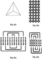
- One part of the bumper 310, preferable the part of the corner, contains more than one apparatuses 2000, like seen in the Fig. 5b.
- Fig. 5c shows an realization option how the apparatuses 2000 could be realized by metalized plastic coating 313 on plastic material 314, hidden after plastic material of the bumper.
- the clear advantage of the approach is that the vehicle having apparatuses 2000, have better cross section as the vehicle without integrated apparatuses 2000, which plays significant role exactly in cases where the radar-based illumination is coming with sharp angle to the corner of the car.
- the typical use case is blind spot detection where moving vehicle is watching the vehicle on the neighboured traffic line, illuminated exactly the corner of the passing vehicle.
- the observing blind spot detection radar system will obtain significantly stronger signal as in case of not having apparatuses 2000 being integrated in the observed vehicle. This may increase the sensitivity in the observing blind spot detector significantly and therefore improve the safety in the traffic.
- integrated apparatuses 2000 in more and more surface of the vehicle environment overall radar cross section and radar general visibility by apparatus 100 will be increased.
- the apparatus 100 of the proposed system can be advantageously be blind spot detection, but also in case or rear radar monitoring and in case of front radar monitoring role, the system performance improvement, regarding radrd sensitivity, and detection range will be increased.
- the third proposed application scenario is that the apparatus 100 is used as part of the traffic infrastructure monitoring system. In that case also in very bead weather condition and in full fog environment the traffic control system many work with the extended sensitivity by monitoring traffic and passing vehicles, if those vehicles would have proposed integrated apparatuses 200 in their embodiment.
- Fig 6 Is showing newly proposed applications scenario with the innovative system. It is proposed to place close to the traffic roads known object 315, having pre-defined and known positions, having arbitrary shape, and arbitrary positions close to the road, beside the traffic lanes and across the traffic lanes, like shown in Fig.6a .
- Prosed known objects 315 have a sets of at lest two and preferably as much as possible apparatuses 2000 being integrated in the object 315.
- the basic idea of introducing the known object 315, with known positions is to provide navigation redundancy, and increase the local accuracy of the vehicle positioning, which could be important especially in case of the autonomous driving.
- reflected waves from the known objects 315 will act as navigation beacon to the moving vehicle system. Those reflected ways will differentiate significantly for other reflection and will be due to large cross sections recognised as enhancement to the navigation and local positioning of the moving vehicle.
- apparatus 100 may calculate the distance to the object, and since the position of the object 315 is known, the system will determinate the position, which may be used in sensor fusion manner for the positioning enhancement. In the case of total fog, where the video system cannot be used, and lidar system has limited observation range, the proposed infrastructure-based solutions of the known object 315 will be very valuable.
- Radrd system may detect those objects at very large distances and recognize them as navigation beacons. This may enhance safety of the autonomous driving.
- Fig. 6c shows special case of the deployment of the known objects 315, where the groups of the apparatuses 2000 are used. The positioning of the group of the apparatuses 2000 within one object 315 may be detected by the apparatuses 100. That means that known object 315 may be used also to send simple coded information related to the combination of the deployed group of apparatuses 2000. That would mend that one each of the field having group of the apparatuses in case of having them are transmitted code 1 and in case of not having them the code 0.
- traffic infrastructure may send codded message to the radrd based system apparatus 100, being in the moving vehicle.
- the sets of the apparatuses 2000 within the known object 315, may be mechanically moved in one of the several positions of the "0" and "1" filed the message to the incoming cars having apparatuses 100, can be sent dynamically, which could dramatically improve the safety in the autonomous driving, by introducing additional communication way from the infrastructure to the moving vehicle.
- the calculated information and events may be used for the statistical evaluation of the data.
- the proposed system being defined by its apparatuses and methods of operations, can be advantageously used for moving robots and machines, in industrial and daily life environments.
- the proposed system being defined by its apparatuses and methods of operations, can be advantageously used for autonomous driving.
- the proposed system By using artificial intelligence algorithmics, with machine learning in the place, the proposed system, being defined by its apparatuses and methods of operations, can be advantageously used for updating real time mapping data, where vehicle has on the board apparatus 100, and apparatuses 2000 are positioned close or across the roads.
Landscapes
- Engineering & Computer Science (AREA)
- Radar, Positioning & Navigation (AREA)
- Remote Sensing (AREA)
- Physics & Mathematics (AREA)
- General Physics & Mathematics (AREA)
- Computer Networks & Wireless Communication (AREA)
- Automation & Control Theory (AREA)
- Aviation & Aerospace Engineering (AREA)
- Electromagnetism (AREA)
- Computer Security & Cryptography (AREA)
- Radar Systems Or Details Thereof (AREA)
- Traffic Control Systems (AREA)
- Navigation (AREA)
Applications Claiming Priority (1)
| Application Number | Priority Date | Filing Date | Title |
|---|---|---|---|
| US16/199,411 US20200166636A1 (en) | 2018-11-26 | 2018-11-26 | MM-wave radar based guiding system |
Publications (2)
| Publication Number | Publication Date |
|---|---|
| EP3657202A2 true EP3657202A2 (fr) | 2020-05-27 |
| EP3657202A3 EP3657202A3 (fr) | 2020-08-05 |
Family
ID=68655437
Family Applications (1)
| Application Number | Title | Priority Date | Filing Date |
|---|---|---|---|
| EP19211315.7A Pending EP3657202A3 (fr) | 2018-11-26 | 2019-11-25 | Système de guidage à base de radar à onde mm et procédés l'utilisant |
Country Status (3)
| Country | Link |
|---|---|
| US (1) | US20200166636A1 (fr) |
| EP (1) | EP3657202A3 (fr) |
| DE (1) | DE202019005611U1 (fr) |
Cited By (2)
| Publication number | Priority date | Publication date | Assignee | Title |
|---|---|---|---|---|
| US20240385618A1 (en) * | 2020-12-10 | 2024-11-21 | Yamabiko Corporation | Working robot system |
| TWI881275B (zh) * | 2023-01-06 | 2025-04-21 | 宏達國際電子股份有限公司 | 投影系統與搭配投影系統使用的隱形眼鏡 |
Families Citing this family (8)
| Publication number | Priority date | Publication date | Assignee | Title |
|---|---|---|---|---|
| US12439003B2 (en) | 2019-12-23 | 2025-10-07 | Waymo Llc | Real-time adjustment of vehicle sensor field of view volume |
| BE1028219B1 (nl) * | 2020-04-20 | 2021-11-24 | Rombit Nv | Werkwijze, systeem en computerprogrammaproduct voor blinde vlek detectie |
| US12345804B2 (en) * | 2021-09-20 | 2025-07-01 | Deere & Company | Systems and methods for adjusting vehicle lane position |
| US12437638B2 (en) * | 2021-09-20 | 2025-10-07 | Deere & Company | Systems and methods for adjusting vehicle lane |
| US20230089124A1 (en) * | 2021-09-20 | 2023-03-23 | DC-001, Inc. dba Spartan Radar | Systems and methods for determining the local position of a vehicle using radar |
| US12361825B2 (en) * | 2021-09-20 | 2025-07-15 | Deere & Company | Traffic signal systems for communicating with vehicle sensors |
| US12100128B2 (en) * | 2022-03-14 | 2024-09-24 | International Business Machines Corporation | Computer analysis of remotely detected images for image identification |
| US20250319841A1 (en) * | 2024-04-10 | 2025-10-16 | Toyota Motor Engineering & Manufacturing North America, Inc. | Systems and methods for detecting passenger restraint device usage |
Citations (5)
| Publication number | Priority date | Publication date | Assignee | Title |
|---|---|---|---|---|
| US5387916A (en) | 1992-07-31 | 1995-02-07 | Westinghouse Electric Corporation | Automotive navigation system and method |
| US20090058638A1 (en) | 2006-09-08 | 2009-03-05 | Symbol Technologies, Inc. | Methods and apparatus for a pervasive locationing and presence-detection system |
| US8350752B2 (en) | 2010-07-09 | 2013-01-08 | Rosemount Tank Radar Ab | Radar level gauge system with bottom reflector and bottom reflector |
| US20150145711A1 (en) | 2013-11-26 | 2015-05-28 | The Regents Of The University Of Michigan | Retro-reflective radar patch antenna target for vehicle and road infrastructure identification |
| US9325077B2 (en) | 2013-11-12 | 2016-04-26 | Rosemount Tank Radar Ab | Radar level gauge system and reflector arrangement |
Family Cites Families (2)
| Publication number | Priority date | Publication date | Assignee | Title |
|---|---|---|---|---|
| US7629899B2 (en) * | 1997-10-22 | 2009-12-08 | Intelligent Technologies International, Inc. | Vehicular communication arrangement and method |
| EP3311192A1 (fr) * | 2015-06-17 | 2018-04-25 | Novelic D.O.O. | Système de capteur à ondes millimétriques pour aide au stationnement |
-
2018
- 2018-11-26 US US16/199,411 patent/US20200166636A1/en not_active Abandoned
-
2019
- 2019-11-25 EP EP19211315.7A patent/EP3657202A3/fr active Pending
- 2019-11-25 DE DE202019005611.4U patent/DE202019005611U1/de active Active
Patent Citations (5)
| Publication number | Priority date | Publication date | Assignee | Title |
|---|---|---|---|---|
| US5387916A (en) | 1992-07-31 | 1995-02-07 | Westinghouse Electric Corporation | Automotive navigation system and method |
| US20090058638A1 (en) | 2006-09-08 | 2009-03-05 | Symbol Technologies, Inc. | Methods and apparatus for a pervasive locationing and presence-detection system |
| US8350752B2 (en) | 2010-07-09 | 2013-01-08 | Rosemount Tank Radar Ab | Radar level gauge system with bottom reflector and bottom reflector |
| US9325077B2 (en) | 2013-11-12 | 2016-04-26 | Rosemount Tank Radar Ab | Radar level gauge system and reflector arrangement |
| US20150145711A1 (en) | 2013-11-26 | 2015-05-28 | The Regents Of The University Of Michigan | Retro-reflective radar patch antenna target for vehicle and road infrastructure identification |
Non-Patent Citations (2)
| Title |
|---|
| "A Passive Re-Directing Van Atta Type Reflector", IEEE ANTENNAS AND WIRELESS PROPAGATION LETTERS, vol. XX, 2018 |
| "Inkjet-Printed Flexible mm-Wave Van-Atta Reflectarrays", IEEE TRANSACTIONS ON MICROWAVE THEORY AND TECHNIQUES, vol. 64, no. 12, December 2016 (2016-12-01), pages 4763 |
Cited By (3)
| Publication number | Priority date | Publication date | Assignee | Title |
|---|---|---|---|---|
| US20240385618A1 (en) * | 2020-12-10 | 2024-11-21 | Yamabiko Corporation | Working robot system |
| US12468301B2 (en) * | 2020-12-10 | 2025-11-11 | Yamabiko Corporation | Working robot system |
| TWI881275B (zh) * | 2023-01-06 | 2025-04-21 | 宏達國際電子股份有限公司 | 投影系統與搭配投影系統使用的隱形眼鏡 |
Also Published As
| Publication number | Publication date |
|---|---|
| EP3657202A3 (fr) | 2020-08-05 |
| DE202019005611U1 (de) | 2021-05-25 |
| US20200166636A1 (en) | 2020-05-28 |
Similar Documents
| Publication | Publication Date | Title |
|---|---|---|
| EP3657202A2 (fr) | Système de guidage à base de radar à onde mm et procédés l'utilisant | |
| Soltanaghaei et al. | Millimetro: mmWave retro-reflective tags for accurate, long range localization | |
| US12366649B2 (en) | Methods, systems, and low power retro-directive RF tags for localization | |
| Feng et al. | Lane detection with a high-resolution automotive radar by introducing a new type of road marking | |
| US20200249337A1 (en) | Radar based inverse detection sensor system | |
| US20260100123A1 (en) | Dynamic Co-Operative Arrays of Electromagnetic Markers for Highly Autonomous Vehicle Location and Cryptographically Secure Transactions | |
| US20170287332A1 (en) | Method and device for monitoring a traffic space | |
| CN113156364B (zh) | 安全系统和方法 | |
| MX2013012902A (es) | Etiqueta interruptor de rfid. | |
| Bu et al. | Pedestrian detection in transit bus application: sensing technologies and safety solutions | |
| JP2021536045A (ja) | 車両による低電磁プロファイルのオブジェクト(対象物)の検出を向上させるためのシステムおよび方法 | |
| US20140267728A1 (en) | Vehicle detection and image capture system and methods for detecting and capturing images of vehicles | |
| IL154835A (en) | A system for identifying friendly or hostile ground elements on a battlefield | |
| US12560698B2 (en) | RF navigation for motor vehicles | |
| WO2018049085A1 (fr) | Infrastructure de navigation pour véhicules à moteur | |
| US20230222908A1 (en) | Roadway information detection system consists of sensors on the autonomous vehicles and devices for the road | |
| CN211505884U (zh) | 一种基于超高频rfid及毫米波雷达的车辆定位装置 | |
| US9047522B1 (en) | Utilization of motion and spatial identification in mobile RFID interrogator | |
| JP2007333539A (ja) | レーダ装置および反射装置 | |
| Long et al. | GPS-Denied ISAC Vehicle Localization Based on mmWave Radar and Identification | |
| Sun et al. | Allergie: Relative vehicular localization with commodity rfid system | |
| Voronov et al. | Radar reflecting pavement markers for vehicle automation | |
| CN115468574A (zh) | 一种用于自动驾驶环境感知的低功耗高精度定位技术 | |
| Regus et al. | Indoor positioning and navigation system for autonomous vehicles based on RFID technology | |
| Wang et al. | A channel awareness vehicle detector |
Legal Events
| Date | Code | Title | Description |
|---|---|---|---|
| PUAI | Public reference made under article 153(3) epc to a published international application that has entered the european phase |
Free format text: ORIGINAL CODE: 0009012 |
|
| STAA | Information on the status of an ep patent application or granted ep patent |
Free format text: STATUS: REQUEST FOR EXAMINATION WAS MADE |
|
| 17P | Request for examination filed |
Effective date: 20191125 |
|
| AK | Designated contracting states |
Kind code of ref document: A2 Designated state(s): AL AT BE BG CH CY CZ DE DK EE ES FI FR GB GR HR HU IE IS IT LI LT LU LV MC MK MT NL NO PL PT RO RS SE SI SK SM TR |
|
| AX | Request for extension of the european patent |
Extension state: BA ME |
|
| PUAL | Search report despatched |
Free format text: ORIGINAL CODE: 0009013 |
|
| AK | Designated contracting states |
Kind code of ref document: A3 Designated state(s): AL AT BE BG CH CY CZ DE DK EE ES FI FR GB GR HR HU IE IS IT LI LT LU LV MC MK MT NL NO PL PT RO RS SE SI SK SM TR |
|
| AX | Request for extension of the european patent |
Extension state: BA ME |
|
| RIC1 | Information provided on ipc code assigned before grant |
Ipc: G01S 13/931 20200101ALI20200702BHEP Ipc: G01S 13/42 20060101ALI20200702BHEP Ipc: G01S 7/03 20060101ALI20200702BHEP Ipc: G01S 7/41 20060101AFI20200702BHEP Ipc: E01F 9/30 20160101ALI20200702BHEP Ipc: G08G 1/16 20060101ALN20200702BHEP Ipc: G01C 21/18 20060101ALI20200702BHEP Ipc: G01S 13/06 20060101ALI20200702BHEP Ipc: G01S 13/88 20060101ALI20200702BHEP Ipc: G01C 21/36 20060101ALI20200702BHEP |
|
| STAA | Information on the status of an ep patent application or granted ep patent |
Free format text: STATUS: EXAMINATION IS IN PROGRESS |
|
| 17Q | First examination report despatched |
Effective date: 20221223 |