EP3657635A1 - Rotor pour une machine asynchrone à géométrie de type barre optimisée en termes de pertes, machine asynchrone ainsi que procédé - Google Patents
Rotor pour une machine asynchrone à géométrie de type barre optimisée en termes de pertes, machine asynchrone ainsi que procédé Download PDFInfo
- Publication number
- EP3657635A1 EP3657635A1 EP18207820.4A EP18207820A EP3657635A1 EP 3657635 A1 EP3657635 A1 EP 3657635A1 EP 18207820 A EP18207820 A EP 18207820A EP 3657635 A1 EP3657635 A1 EP 3657635A1
- Authority
- EP
- European Patent Office
- Prior art keywords
- rotor
- elements
- grooves
- asynchronous machine
- region
- Prior art date
- Legal status (The legal status is an assumption and is not a legal conclusion. Google has not performed a legal analysis and makes no representation as to the accuracy of the status listed.)
- Withdrawn
Links
- 238000000034 method Methods 0.000 title description 10
- 239000004020 conductor Substances 0.000 claims abstract description 21
- 238000004519 manufacturing process Methods 0.000 claims abstract description 13
- 239000000463 material Substances 0.000 claims description 12
- 238000001816 cooling Methods 0.000 claims description 8
- 239000002826 coolant Substances 0.000 claims description 3
- 239000012777 electrically insulating material Substances 0.000 claims description 2
- 239000000945 filler Substances 0.000 claims description 2
- 230000003993 interaction Effects 0.000 claims description 2
- 230000002787 reinforcement Effects 0.000 description 16
- XEEYBQQBJWHFJM-UHFFFAOYSA-N Iron Chemical group [Fe] XEEYBQQBJWHFJM-UHFFFAOYSA-N 0.000 description 5
- RYGMFSIKBFXOCR-UHFFFAOYSA-N Copper Chemical compound [Cu] RYGMFSIKBFXOCR-UHFFFAOYSA-N 0.000 description 4
- XAGFODPZIPBFFR-UHFFFAOYSA-N aluminium Chemical compound [Al] XAGFODPZIPBFFR-UHFFFAOYSA-N 0.000 description 4
- 229910052782 aluminium Inorganic materials 0.000 description 4
- 239000010949 copper Substances 0.000 description 4
- 229910052802 copper Inorganic materials 0.000 description 4
- 238000004512 die casting Methods 0.000 description 4
- 230000002093 peripheral effect Effects 0.000 description 4
- 229910045601 alloy Inorganic materials 0.000 description 3
- 239000000956 alloy Substances 0.000 description 3
- RTAQQCXQSZGOHL-UHFFFAOYSA-N Titanium Chemical compound [Ti] RTAQQCXQSZGOHL-UHFFFAOYSA-N 0.000 description 2
- 238000005266 casting Methods 0.000 description 2
- 229910052742 iron Inorganic materials 0.000 description 2
- 239000010935 stainless steel Substances 0.000 description 2
- 229910001220 stainless steel Inorganic materials 0.000 description 2
- 239000010936 titanium Substances 0.000 description 2
- 229910052719 titanium Inorganic materials 0.000 description 2
- 239000000654 additive Substances 0.000 description 1
- 230000000996 additive effect Effects 0.000 description 1
- 239000000919 ceramic Substances 0.000 description 1
- 229910010293 ceramic material Inorganic materials 0.000 description 1
- 150000001875 compounds Chemical class 0.000 description 1
- 239000000110 cooling liquid Substances 0.000 description 1
- 230000001419 dependent effect Effects 0.000 description 1
- 238000011161 development Methods 0.000 description 1
- 230000018109 developmental process Effects 0.000 description 1
- 230000000694 effects Effects 0.000 description 1
- 230000017525 heat dissipation Effects 0.000 description 1
- 238000003475 lamination Methods 0.000 description 1
- 238000003754 machining Methods 0.000 description 1
- 239000012811 non-conductive material Substances 0.000 description 1
- 230000003014 reinforcing effect Effects 0.000 description 1
- 238000007789 sealing Methods 0.000 description 1
- 238000009423 ventilation Methods 0.000 description 1
- XLYOFNOQVPJJNP-UHFFFAOYSA-N water Substances O XLYOFNOQVPJJNP-UHFFFAOYSA-N 0.000 description 1
- 238000004804 winding Methods 0.000 description 1
Images


Classifications
-
- H—ELECTRICITY
- H02—GENERATION; CONVERSION OR DISTRIBUTION OF ELECTRIC POWER
- H02K—DYNAMO-ELECTRIC MACHINES
- H02K17/00—Asynchronous induction motors; Asynchronous induction generators
- H02K17/02—Asynchronous induction motors
- H02K17/16—Asynchronous induction motors having rotors with internally short-circuited windings, e.g. cage rotors
- H02K17/20—Asynchronous induction motors having rotors with internally short-circuited windings, e.g. cage rotors having deep-bar rotors
-
- H—ELECTRICITY
- H02—GENERATION; CONVERSION OR DISTRIBUTION OF ELECTRIC POWER
- H02K—DYNAMO-ELECTRIC MACHINES
- H02K15/00—Processes or apparatus specially adapted for manufacturing, assembling, maintaining or repairing of dynamo-electric machines
- H02K15/02—Processes or apparatus specially adapted for manufacturing, assembling, maintaining or repairing of dynamo-electric machines of stator or rotor bodies
- H02K15/021—Magnetic cores
- H02K15/023—Cage rotors
-
- H—ELECTRICITY
- H02—GENERATION; CONVERSION OR DISTRIBUTION OF ELECTRIC POWER
- H02K—DYNAMO-ELECTRIC MACHINES
- H02K3/00—Details of windings
- H02K3/46—Fastening of windings on the stator or rotor structure
- H02K3/48—Fastening of windings on the stator or rotor structure in slots
- H02K3/487—Slot-closing devices
Definitions
- the present invention relates to a rotor for an asynchronous machine.
- the rotor comprises a laminated core which has a plurality of grooves.
- the rotor comprises a plurality of rod elements, one of the rod elements being arranged in one of the grooves and the respective rod elements being made of an electrically conductive material.
- the present invention relates to an asynchronous machine with such a rotor.
- the present invention relates to a method for producing a rotor for an asynchronous machine.
- Asynchronous machines have a rotor or rotor, which has a laminated core with a plurality of grooves. These grooves are usually filled with electrically conductive rod elements or rotor bars. In asynchronous machines, disproportionately high losses occur in the upper third of each rotor bar, depending on the groove geometry (trapezoidal, drop or rectangular groove) and the ratio of rotor to stator usable number. These losses arise primarily from field lines that cross over the conductive rod material and thereby induce eddy current losses in the rotor rods. This applies to both closed and open groove geometries. This effect is particularly disadvantageous in the case of open groove geometries, in the case of trapezoidal or rectangular groove shapes and in the case of groove ratios in which the number of rotor grooves is greater than the number of stator grooves.
- the slot slots in the rotor are cast with a conductive material, for example aluminum or copper, in the widely used, inexpensive die-casting processes.
- the electrically conductive material in the slot slot causes such high losses that the slot slot is often subsequently machined freely in order to limit the rotor losses.
- the losses in the slot can be at least as high as in the complete rotor bar. Overall, the losses described above are accepted and thus the poorer utilization of the electrical machine is accepted.
- the rotors for asynchronous machines usually have a short-circuit cage with corresponding short-circuit rings.
- the respective rotor bars are electrically connected to one another by means of these short-circuit rings.
- the peripheral speed and thus also the maximum speed of the rotor are limited in particular by the material strength of the short-circuit ring.
- Materials with a high electrical conductivity are typically used for the short-circuit cage in order to keep the ohmic losses in the rotor low.
- these materials have poor mechanical properties and in particular a low tensile strength, so that alloys or additional reinforcement are used to increase the peripheral speed of the short-circuit ring.
- a rotor according to the invention for an asynchronous machine comprises a laminated core which has a plurality of grooves.
- the rotor comprises a plurality of rod elements, one of the rod elements being arranged in one of the grooves and the respective rod elements being made of an electrically conductive material.
- the respective grooves in the radial direction of the rotor have a first area and a second area adjacent to the first area, the second area facing an outside of the rotor.
- the bar elements are arranged in the respective first areas and the respective second areas are free of the bar elements.
- the rotor can be used in an electrical machine and in particular in an asynchronous machine.
- the rotor can also be called a rotor.
- the rotor comprises the laminated core, which can be made from a plurality of individual laminations.
- This laminated core comprises the grooves, which can be arranged at a uniform distance from one another along a circumferential direction of the rotor.
- the respective grooves can extend along an axial direction of the rotor.
- the rod elements are arranged in the respective grooves at least in some areas.
- the rod elements are made of an electrically conductive material, for example copper or aluminum.
- the rotor can have short-circuit rings with which the rod elements are electrically connected to one another.
- the short-circuit rings can form a short-circuit cage of the rotor together with the rod elements.
- the respective grooves - viewed in the radial direction of the rotor - are divided into the first area and the second area.
- the first area is assigned to a lower area of the groove, which faces a center of the rotor or a shaft of the rotor.
- the second area can face an upper area or the outside of the rotor.
- the respective rod elements are only arranged in the first area of the respective grooves.
- the second area of the respective grooves is free of the rod elements. No bar elements are therefore arranged in the second area.
- the second area can be filled with air. A free space or an air-filled space can therefore be located within the groove above the rod element.
- An amagnetic and non-conductive material can therefore be arranged in the second region.
- the eddy current losses due to field lines that otherwise run across conductive material of the rotor bars can be reduced. In this way, the ohmic losses can be reduced. This is particularly advantageous if the grooves are trapezoidal or rectangular in cross section.
- the arrangement of the respective rod elements in the first area can be achieved by appropriate dimensioning of the rod elements. Overall, efficient operation of the rotor for the asynchronous machine can thus be achieved in a simple manner.
- the respective first regions preferably extend over at least two thirds of a total radial length of the respective grooves.
- the respective second regions can extend over a maximum of one third of the total radial length.
- the total radial length can describe the length or extent of the groove in the radial direction.
- the geometry of the rod elements is selected in such a way that the permissible mechanical stresses under centrifugal force are not exceeded and that there is no appreciable increase in the stray field within the groove.
- the respective grooves have at least one elevation by means of which the rod element is held in the groove in the radial direction. This elevation can be located on an upper side of the bar element. The rod element can be held in the radial direction by this form fit. It can also be provided that the groove has at least two elevations.
- the respective grooves have elevations and the respective rod elements have recesses corresponding to the elevations, the respective rod elements being held in the radial direction by an interaction of the elevations and recesses.
- the respective grooves can therefore have one or more elevations. These elevations can, for example, extend perpendicular to an inner wall of the groove. These elevations can be designed as lugs, fillets, webs or the like.
- the bar element has recesses corresponding to the elevations. The elevations are at least partially arranged in the corresponding recesses. This positive connection allows the rod elements to be held in the grooves in the radial direction.
- the rod elements can be positioned and fixed in the grooves or on the laminated core.
- the respective grooves have recesses and the respective rod elements have elevations corresponding to the recesses.
- the rod elements can thus be reliably held in the first region of the grooves during operation of the electrical machine.
- the respective second regions form a cooling channel for guiding a cooling medium.
- the second areas or the free spaces above the rod elements can also be used to cool the rotor.
- the second areas or the cooling channels can serve to guide a cooling air flow.
- air cooling can be implemented in the form of draft ventilation.
- the cooling channels serve to guide a cooling liquid. Water or oil cooling can thus be implemented, for example. It is particularly advantageous that the heat can be dissipated directly at the loss source, for example the rotor tooth heads and the rod elements. An improved heat dissipation can thus be achieved overall.
- the rotor has a plurality of filling elements which are arranged in the second regions of the respective grooves, the filling elements being made from an amagnetic material and / or an electrically insulating material.
- a respective filling element can thus be arranged in the upper third or second region of the grooves.
- the upper third above the bar elements can be filled with an amagnetic, non-conductive or poorly conductive material.
- the material from which the respective filling elements are made is temperature-resistant.
- the material can be, for example, a ceramic material, stainless steel, titanium, an Inocel® alloy, a casting compound or the like.
- the respective filling elements can be designed such that they fill in the second area completely.
- the arrangement of the filler elements in the second area of the grooves results in a positive fit, which fixes and positions the rod elements.
- the filling elements can be used as a sealing element in the die-casting process in the manufacture of the rotor.
- the respective filling elements can first be arranged in the respective second regions of the grooves and then an electrically conductive material can be introduced into the first regions of the respective grooves to produce the respective rod elements.
- the respective grooves have groove slots on the outside, wherein the filling element can also be arranged in the useful slots. Because there is no electrically conductive material in the slot, the losses can be significantly reduced. In addition, there is no need for subsequent machining of the slot slots. In comparison to the prior art, an additional manufacturing step can thus be dispensed with.
- the arrangement of the filling elements in the second region of the grooves can also prevent the conductive material from getting into the groove slots during the production of the rod elements during a die-casting process.
- the rotor has a ring element at radial ends and the respective filling elements are connected to the ring elements.
- the rotor can have two short-circuit rings which are electrically connected to the respective rod elements.
- the short-circuit rings can form the so-called short-circuit cage together with the rod elements.
- the rotor can have two ring elements which can be connected to the respective filling elements. These ring elements can be arranged on the outer radial ends of the short-circuit rings.
- the ring elements can form a cage device together with the filling elements, which also serves as a "reinforcement cage" or reinforcement can be called.
- this reinforcement cage has the ring elements over the actual short-circuit rings. Due to the increased strength properties of the reinforcement cage compared to the material of the short-circuit cage, the mechanical stresses in the short-circuit rings are reduced under centrifugal force. In this way, higher peripheral speeds and thus higher maximum speeds can be realized.
- the respective ring elements have a circumferential securing element for the axial positioning of the respective ring element.
- the securing element can be designed as a circumferential groove.
- the securing element can extend in the radial direction inwards or in the direction of the center of the rotor or outwards. This securing element is used to axially fix the reinforcement cage.
- the securing element serves to axially fix the ring element to the short-circuit ring.
- the short-circuiting ring can have a recess corresponding to the securing element.
- the respective ring elements have a plurality of securing elements.
- every second of the filling elements is arranged on one of the ring elements in the circumferential direction and the other of the filling elements are arranged on the other of the ring elements, the respective filling elements having a length which corresponds to a length of the laminated core.
- the reinforcement cage can be formed from two parts which are connected to one another.
- a first part can have a first ring element, in which every second filling element is connected to a first ring element in the circumferential direction.
- the first ring element can also be formed in one piece with these filling elements.
- the second part can comprise a second ring element, wherein the second ring element can be connected to the other filling elements or can be formed in one piece with them.
- the second too Ring element every second of the filling elements can be arranged in the circumferential direction.
- the first part and the second part are connected to one another to form the reinforcement cage.
- the respective filling elements can have corresponding elevations at the free ends, which are connected to corresponding recesses in the ring element of the other part. This enables the reinforcement cage to be easily manufactured.
- partial filling elements are arranged on each of the ring elements, the respective partial filling elements having a length which corresponds to half the length of the laminated core, and two corresponding and connected partial filling elements each forming one of the filling elements.
- the reinforcement cage can be formed from two parts.
- the respective partial filling elements are arranged on each of the ring elements in the circumferential direction.
- the respective partial filling elements can have the same length, which in particular corresponds to half the length of the laminated core or half the length of the iron core.
- the partial filling elements of the first part can have elevations at the respective free ends.
- the partial filling elements of the second part can have recesses corresponding to these elevations at the respective free ends.
- the elevations and recesses on the partial filling elements of a part can also be formed alternately.
- the partial filling elements of the first part and the second part can be connected to one another in a manner similar to a tongue and groove system.
- the surveys can reach into the corresponding recesses. This also enables simple and inexpensive production.
- An asynchronous machine according to the invention comprises a rotor according to the invention.
- the asynchronous machine comprises a stator, which can also be referred to as a stator.
- the rotor is rotatable with respect to the stator.
- the stator can have a plurality of grooves. Here is particular provided that a number of grooves of the stator differs from a number of grooves of the rotor.
- a method according to the invention is used to manufacture a rotor for an asynchronous machine.
- the method comprises providing a laminated core that has a plurality of grooves.
- the method comprises producing a plurality of rod elements from an electrically conductive material and arranging one of the rod elements in each of the grooves.
- the respective grooves in the radial direction of the rotor have a first area and a second area adjacent to the first area, the second area facing an outside of the rotor.
- the bar elements are arranged in the respective first areas and the respective second areas are free of the bar elements.
- the laminated core can first be provided.
- the filling elements of the reinforcement cage or the cage device can then be provided.
- the respective filling elements can be arranged in the second areas of the respective grooves.
- the electrically conductive material can then be introduced into the first regions of the respective grooves.
- An additive manufacturing process, a casting process or a die casting process can be used for this. In this way, the rod elements and the short-circuit rings can be manufactured.
- the ring elements of the cage device can then be arranged and positioned on the short-circuit rings.
- FIG. 1 shows a section of a sectional side view of an asynchronous machine 1 according to the prior art.
- the asynchronous machine 1 comprises a stator 2, which has a plurality of slots 3 or stator slots. A winding of the stator 2 is arranged in these slots 3.
- the asynchronous machine 1 comprises a rotor 4, which is concentric and internal to the stator 2.
- the rotor 4 is rotatable with respect to the stator 2.
- the rotor 4 comprises a plurality of grooves 5 or rotor grooves, which are introduced into a laminated core 10.
- Runner bars 6 are arranged in the respective grooves 5.
- These rotor bars 6 are made of an electrically conductive material, for example copper or aluminum.
- FIG 2 shows a section of a sectional side view of an asynchronous machine 1 according to a first embodiment.
- the stator 2 corresponds to the stator 2 of the asynchronous machine 1 according to the prior art FIG. 1 .
- the rotor 4 also has the grooves 5.
- the respective grooves 5 are divided into a first area 7 and a second area 8.
- the first region 7 faces a center point or a shaft 22 of the rotor 4 and the second region 8 faces an outer side 19 or upper side of the rotor 4.
- the first area 7 and the second area 8 adjoin one another.
- the first area occupies at least two thirds of a total radial length of the groove 4 and the second area 8 occupies a maximum of one third of the total radial length.
- a rod element 9 is arranged in the first area 7, which replaces the rotor bar 6 or serves as a rotor bar 6.
- This rod element 9 is made of an electrically conductive material, in particular copper or aluminum.
- the second area 8 is free of the rod element 9.
- the second area 8 can be filled with air.
- the second area 8 can also serve as a cooling channel for guiding a cooling medium.
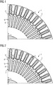
- FIG 3 shows a section of a sectional side view of an asynchronous machine 1 according to a further embodiment.
- the grooves 5 are compared to the grooves 5 according to FIG 2 broader and have a closed groove geometry.
- the rod elements 9 can in principle be used for different groove geometries.
- FIG 4 shows a section of a sectional side view of an asynchronous machine 1 according to a further embodiment.
- the grooves 5 in comparison to the grooves FIG 2 additional surveys 11. These elevations 11 rest on an upper side of the rod elements 9.
- the rod elements 9 can be secured or held in the radial direction r during operation of the asynchronous machine 1.
- FIG 5 shows a section of a sectional side view of a rotor 4 according to a further embodiment.
- the grooves 5 have elevations 11.
- the rod element 9 has cutouts 12 which correspond to the elevations 11. The rod element 9 can be secured in the radial direction r by this positive connection.
- FIG 6 shows a section of a sectional side view of an asynchronous machine 1 according to a further embodiment.
- a filling element 13 is arranged in the second region 8 of the groove 5.
- This filling element 13 is made of an amagnetic material which is not electrically conductive or has a very low conductivity. The material is also temperature-resistant.
- the filling elements 13 can be made of a ceramic, stainless steel, titanium or the like. The eddy current losses can also be reduced by these filling elements 13.
- the rod element 9 is held in the groove 5 by the filling element 13.
- FIG 7 shows a section of a sectional side view of an asynchronous machine 1 according to a further embodiment.
- slot slots 14 are also filled with the filling element 13 or the material of the filling elements 13. Compared to slot slots 14 which are filled with an electrically conductive material, this results in significantly lower losses.
- FIG 8 shows a section of a perspective view of part 15 of a cage device.
- the cage device which can also be referred to as a "reinforcement cage”
- the respective ring elements 16 can be placed externally (radially) on the short-circuit rings 23 of the rotor 4.
- every second filling element 13 is arranged on the ring element 16 in the part 15 in the circumferential direction U of the rotor 4 or the ring element 16.
- the respective filling elements 13 extend along an axial direction a of the rotor 4 and have a length which corresponds to an iron package length of the rotor 4 or a length of the laminated core 10.
- the filling elements 14 have elevations 17, which can be connected to corresponding recesses 18 of an identical part 15.
- the recesses 18 serve to receive the elevations 17 of the filling elements 13 of another part 15. In this way, two parts 15 can be connected to form a “reinforcement cage”.
- FIG. 9 shows a detail of a perspective view of part 15 of a cage device according to a further embodiment.
- This part 15 also has a ring element 16.
- Partial filling elements 20 are arranged uniformly distributed on the ring element 16 in the circumferential direction U. These partial filling elements 20 extend along the axial direction a of the rotor 4 and have a length which corresponds to half the iron packet length of the rotor 4.
- the partial filling elements 20 alternately have elevations 17 and recesses 18 at the free ends in the circumferential direction U. These elevations 17 and recesses 18 can be connected to corresponding recesses 18 and elevations 17 of an identical part 15.
- the "reinforcement cage" can thus be provided.
- FIG 10 shows part 15 according to FIG. 9 in another perspective view. It can be seen here that the ring element 16 has circumferential securing element 21 for axially positioning the ring element 16 on a short-circuit cage.
- the securing element 21 extends inwards along the radial direction r. It can also be provided that the securing element 21 extends outward in the radial direction r.
- FIG 11 shows a section of a sectional view of the rotor 4.
- the laminated core 10 can be seen, which is connected to the shaft 22.
- the rod element 9, which is arranged in the first region 7 of the groove 5, and the filling element 13, which is arranged in the second region 8 of the groove 5, are shown.
- the short-circuit ring 23 is shown, which is connected to the rod elements 9.
- the ring element 16 is arranged in the radial direction r on or above the short-circuit ring 23.
- the securing element 21 is arranged in a corresponding recess 24 in the short-circuit ring 23. Axial positioning of the ring element 21 can thus be achieved.
- the speed stability or the peripheral speed can be increased by reinforcing the short-circuit ring 23. This is achieved in combination with the loss-optimized geometry of the rod elements 9.
Landscapes
- Engineering & Computer Science (AREA)
- Power Engineering (AREA)
- Manufacturing & Machinery (AREA)
- Iron Core Of Rotating Electric Machines (AREA)
Priority Applications (1)
| Application Number | Priority Date | Filing Date | Title |
|---|---|---|---|
| EP18207820.4A EP3657635A1 (fr) | 2018-11-22 | 2018-11-22 | Rotor pour une machine asynchrone à géométrie de type barre optimisée en termes de pertes, machine asynchrone ainsi que procédé |
Applications Claiming Priority (1)
| Application Number | Priority Date | Filing Date | Title |
|---|---|---|---|
| EP18207820.4A EP3657635A1 (fr) | 2018-11-22 | 2018-11-22 | Rotor pour une machine asynchrone à géométrie de type barre optimisée en termes de pertes, machine asynchrone ainsi que procédé |
Publications (1)
| Publication Number | Publication Date |
|---|---|
| EP3657635A1 true EP3657635A1 (fr) | 2020-05-27 |
Family
ID=64453383
Family Applications (1)
| Application Number | Title | Priority Date | Filing Date |
|---|---|---|---|
| EP18207820.4A Withdrawn EP3657635A1 (fr) | 2018-11-22 | 2018-11-22 | Rotor pour une machine asynchrone à géométrie de type barre optimisée en termes de pertes, machine asynchrone ainsi que procédé |
Country Status (1)
| Country | Link |
|---|---|
| EP (1) | EP3657635A1 (fr) |
Cited By (2)
| Publication number | Priority date | Publication date | Assignee | Title |
|---|---|---|---|---|
| DE102022208673A1 (de) | 2022-08-22 | 2024-02-22 | Volkswagen Aktiengesellschaft | Verfahren zur Fertigung eines Läufers einer elektrischen Maschine |
| EP4718693A1 (fr) * | 2024-09-27 | 2026-04-01 | Stanzwerk AG | Rotor à cage d'écureuil, méthode de fabrication d'un rotor à cage d'écureuil par moulage et ensemble de formes de moulage utiles pour la mise en oeuvre de la méthode |
Citations (7)
| Publication number | Priority date | Publication date | Assignee | Title |
|---|---|---|---|---|
| DE19729432C1 (de) * | 1997-07-09 | 1999-01-14 | Siemens Ag | Asynchronmaschine mit Kurzschlußläufer |
| EP1039618A1 (fr) * | 1999-03-15 | 2000-09-27 | Loher Aktiengesellschaft | Cage de court-circuit pour une machine électrique, de préférence machine asynchrone |
| US20080174203A1 (en) * | 2007-01-19 | 2008-07-24 | Nidec Corporation | Motor |
| US20130033144A1 (en) * | 2011-08-04 | 2013-02-07 | GM Global Technology Operations LLC | Stir-welded induction rotor |
| EP2744089A1 (fr) * | 2012-12-14 | 2014-06-18 | Siemens Aktiengesellschaft | Cage d'écureuil sécurisée |
| US20140252910A1 (en) * | 2013-03-06 | 2014-09-11 | Hitachi, Ltd. | Induction machine |
| WO2018024606A1 (fr) * | 2016-08-05 | 2018-02-08 | Volabo Gmbh | Machine électrique |
-
2018
- 2018-11-22 EP EP18207820.4A patent/EP3657635A1/fr not_active Withdrawn
Patent Citations (7)
| Publication number | Priority date | Publication date | Assignee | Title |
|---|---|---|---|---|
| DE19729432C1 (de) * | 1997-07-09 | 1999-01-14 | Siemens Ag | Asynchronmaschine mit Kurzschlußläufer |
| EP1039618A1 (fr) * | 1999-03-15 | 2000-09-27 | Loher Aktiengesellschaft | Cage de court-circuit pour une machine électrique, de préférence machine asynchrone |
| US20080174203A1 (en) * | 2007-01-19 | 2008-07-24 | Nidec Corporation | Motor |
| US20130033144A1 (en) * | 2011-08-04 | 2013-02-07 | GM Global Technology Operations LLC | Stir-welded induction rotor |
| EP2744089A1 (fr) * | 2012-12-14 | 2014-06-18 | Siemens Aktiengesellschaft | Cage d'écureuil sécurisée |
| US20140252910A1 (en) * | 2013-03-06 | 2014-09-11 | Hitachi, Ltd. | Induction machine |
| WO2018024606A1 (fr) * | 2016-08-05 | 2018-02-08 | Volabo Gmbh | Machine électrique |
Cited By (2)
| Publication number | Priority date | Publication date | Assignee | Title |
|---|---|---|---|---|
| DE102022208673A1 (de) | 2022-08-22 | 2024-02-22 | Volkswagen Aktiengesellschaft | Verfahren zur Fertigung eines Läufers einer elektrischen Maschine |
| EP4718693A1 (fr) * | 2024-09-27 | 2026-04-01 | Stanzwerk AG | Rotor à cage d'écureuil, méthode de fabrication d'un rotor à cage d'écureuil par moulage et ensemble de formes de moulage utiles pour la mise en oeuvre de la méthode |
Similar Documents
| Publication | Publication Date | Title |
|---|---|---|
| DE102021214491A1 (de) | Stator für eine elektrische Maschine und elektrische Maschine | |
| DE102015215762A1 (de) | Blechpaket und Verfahren zu dessen Herstellung | |
| EP3469694B1 (fr) | Rotor en court-circuit en particulier pour dispositifs a haut regime | |
| EP2918005B1 (fr) | Cage d'écureuil sécurisée | |
| WO2021032240A1 (fr) | Stator et machine électrique tournante | |
| DE102016124830B4 (de) | Blech zur Bildung eines Blechpaketes für einen Rotor einer elektrischen Maschine | |
| DE102020101149A1 (de) | Axialflussmaschine mit mechanisch fixierten Statorkernen mit radial verlaufenden Blechsegmenten | |
| DE102022213027A1 (de) | Rotor und elektrische Maschine | |
| WO2016055199A2 (fr) | Rotor à cage pour machine électrique asynchrone comportant des tirants qui stabilisent une bague de court-circuit | |
| EP2523321A1 (fr) | Moteur linéaire cylindrique doté d'un pied en tôle | |
| DE102011083577A1 (de) | Elektrische Maschine mit Stator mit variablem Nutabstand | |
| EP3657635A1 (fr) | Rotor pour une machine asynchrone à géométrie de type barre optimisée en termes de pertes, machine asynchrone ainsi que procédé | |
| EP3205004A1 (fr) | Rotor à cage destiné à un moteur électrique asynchrone, muni d'un disque de support stabilisant la bague de court-circuit | |
| WO2021110193A1 (fr) | Bobine, procédé de production d'une bobine et machine rotative électrique | |
| EP3145059A1 (fr) | Cage d'ecureuil | |
| DE102024129046A1 (de) | Kuhlseparatoren fur einen gewickelten rotor | |
| DE102015202004A1 (de) | Käfigläuferrotor mit stabilem Kurzschlussring für eine elektrische Asynchronmaschine sowie Verfahren zum Fertigen desselben | |
| DE102019124256A1 (de) | Elektrische Maschine mit einer bestimmten Positionierung verschiedener Vertiefungen an einem nass laufenden Stator | |
| DE102023201638A1 (de) | Rotor, Asynchronmaschine und Kraftfahrzeug | |
| EP3900156B1 (fr) | Noyau feuilleté pour une machine électrique | |
| DE102022120771A1 (de) | Rotor für eine elektrische Traktionsmaschine eines Kraftfahrzeugs, elektrische Traktionsmaschine für ein Kraftfahrzeug sowie Blechpaket für eine elektrische Traktionsmaschine | |
| DE102023129917B3 (de) | Rotoranordnung, Elektromaschine und Verfahren zur Herstellung | |
| DE102023121670A1 (de) | Wicklung und elektrische Rotationsmaschine | |
| DE102024103306A1 (de) | Stator für eine elektrische Maschine und elektrische Maschine | |
| DE102023120466A1 (de) | Stator für eine elektrische Maschine sowie Kraftfahrzeug mit einer elektrischen Maschine |
Legal Events
| Date | Code | Title | Description |
|---|---|---|---|
| PUAI | Public reference made under article 153(3) epc to a published international application that has entered the european phase |
Free format text: ORIGINAL CODE: 0009012 |
|
| STAA | Information on the status of an ep patent application or granted ep patent |
Free format text: STATUS: THE APPLICATION HAS BEEN PUBLISHED |
|
| AK | Designated contracting states |
Kind code of ref document: A1 Designated state(s): AL AT BE BG CH CY CZ DE DK EE ES FI FR GB GR HR HU IE IS IT LI LT LU LV MC MK MT NL NO PL PT RO RS SE SI SK SM TR |
|
| AX | Request for extension of the european patent |
Extension state: BA ME |
|
| STAA | Information on the status of an ep patent application or granted ep patent |
Free format text: STATUS: THE APPLICATION IS DEEMED TO BE WITHDRAWN |
|
| 18D | Application deemed to be withdrawn |
Effective date: 20201128 |