EP3657641B1 - Moteur - Google Patents
Moteur Download PDFInfo
- Publication number
- EP3657641B1 EP3657641B1 EP19210106.1A EP19210106A EP3657641B1 EP 3657641 B1 EP3657641 B1 EP 3657641B1 EP 19210106 A EP19210106 A EP 19210106A EP 3657641 B1 EP3657641 B1 EP 3657641B1
- Authority
- EP
- European Patent Office
- Prior art keywords
- rotor
- rotor core
- electrical steel
- steel sheets
- end cover
- Prior art date
- Legal status (The legal status is an assumption and is not a legal conclusion. Google has not performed a legal analysis and makes no representation as to the accuracy of the status listed.)
- Active
Links
Images



Classifications
-
- H—ELECTRICITY
- H02—GENERATION; CONVERSION OR DISTRIBUTION OF ELECTRIC POWER
- H02K—DYNAMO-ELECTRIC MACHINES
- H02K1/00—Details of the magnetic circuit
- H02K1/06—Details of the magnetic circuit characterised by the shape, form or construction
- H02K1/22—Rotating parts of the magnetic circuit
- H02K1/27—Rotor cores with permanent magnets
- H02K1/2786—Outer rotors
- H02K1/2787—Outer rotors the magnetisation axis of the magnets being perpendicular to the rotor axis
- H02K1/2789—Outer rotors the magnetisation axis of the magnets being perpendicular to the rotor axis the rotor consisting of two or more circumferentially positioned magnets
- H02K1/2791—Surface mounted magnets; Inset magnets
-
- H—ELECTRICITY
- H02—GENERATION; CONVERSION OR DISTRIBUTION OF ELECTRIC POWER
- H02K—DYNAMO-ELECTRIC MACHINES
- H02K1/00—Details of the magnetic circuit
- H02K1/06—Details of the magnetic circuit characterised by the shape, form or construction
- H02K1/22—Rotating parts of the magnetic circuit
- H02K1/27—Rotor cores with permanent magnets
-
- H—ELECTRICITY
- H02—GENERATION; CONVERSION OR DISTRIBUTION OF ELECTRIC POWER
- H02K—DYNAMO-ELECTRIC MACHINES
- H02K1/00—Details of the magnetic circuit
- H02K1/06—Details of the magnetic circuit characterised by the shape, form or construction
- H02K1/22—Rotating parts of the magnetic circuit
-
- H—ELECTRICITY
- H02—GENERATION; CONVERSION OR DISTRIBUTION OF ELECTRIC POWER
- H02K—DYNAMO-ELECTRIC MACHINES
- H02K1/00—Details of the magnetic circuit
- H02K1/06—Details of the magnetic circuit characterised by the shape, form or construction
- H02K1/22—Rotating parts of the magnetic circuit
- H02K1/27—Rotor cores with permanent magnets
- H02K1/2706—Inner rotors
-
- H—ELECTRICITY
- H02—GENERATION; CONVERSION OR DISTRIBUTION OF ELECTRIC POWER
- H02K—DYNAMO-ELECTRIC MACHINES
- H02K1/00—Details of the magnetic circuit
- H02K1/06—Details of the magnetic circuit characterised by the shape, form or construction
- H02K1/22—Rotating parts of the magnetic circuit
- H02K1/27—Rotor cores with permanent magnets
- H02K1/2706—Inner rotors
- H02K1/272—Inner rotors the magnetisation axis of the magnets being perpendicular to the rotor axis
- H02K1/274—Inner rotors the magnetisation axis of the magnets being perpendicular to the rotor axis the rotor consisting of two or more circumferentially positioned magnets
-
- H—ELECTRICITY
- H02—GENERATION; CONVERSION OR DISTRIBUTION OF ELECTRIC POWER
- H02K—DYNAMO-ELECTRIC MACHINES
- H02K1/00—Details of the magnetic circuit
- H02K1/06—Details of the magnetic circuit characterised by the shape, form or construction
- H02K1/22—Rotating parts of the magnetic circuit
- H02K1/27—Rotor cores with permanent magnets
- H02K1/2706—Inner rotors
- H02K1/272—Inner rotors the magnetisation axis of the magnets being perpendicular to the rotor axis
- H02K1/274—Inner rotors the magnetisation axis of the magnets being perpendicular to the rotor axis the rotor consisting of two or more circumferentially positioned magnets
- H02K1/2753—Inner rotors the magnetisation axis of the magnets being perpendicular to the rotor axis the rotor consisting of two or more circumferentially positioned magnets the rotor consisting of magnets or groups of magnets arranged with alternating polarity
- H02K1/276—Magnets embedded in the magnetic core, e.g. interior permanent magnets [IPM]
-
- H—ELECTRICITY
- H02—GENERATION; CONVERSION OR DISTRIBUTION OF ELECTRIC POWER
- H02K—DYNAMO-ELECTRIC MACHINES
- H02K1/00—Details of the magnetic circuit
- H02K1/06—Details of the magnetic circuit characterised by the shape, form or construction
- H02K1/22—Rotating parts of the magnetic circuit
- H02K1/27—Rotor cores with permanent magnets
- H02K1/2706—Inner rotors
- H02K1/272—Inner rotors the magnetisation axis of the magnets being perpendicular to the rotor axis
- H02K1/274—Inner rotors the magnetisation axis of the magnets being perpendicular to the rotor axis the rotor consisting of two or more circumferentially positioned magnets
- H02K1/2753—Inner rotors the magnetisation axis of the magnets being perpendicular to the rotor axis the rotor consisting of two or more circumferentially positioned magnets the rotor consisting of magnets or groups of magnets arranged with alternating polarity
- H02K1/276—Magnets embedded in the magnetic core, e.g. interior permanent magnets [IPM]
- H02K1/2766—Magnets embedded in the magnetic core, e.g. interior permanent magnets [IPM] having a flux concentration effect
-
- H—ELECTRICITY
- H02—GENERATION; CONVERSION OR DISTRIBUTION OF ELECTRIC POWER
- H02K—DYNAMO-ELECTRIC MACHINES
- H02K1/00—Details of the magnetic circuit
- H02K1/06—Details of the magnetic circuit characterised by the shape, form or construction
- H02K1/22—Rotating parts of the magnetic circuit
- H02K1/27—Rotor cores with permanent magnets
- H02K1/2786—Outer rotors
-
- H—ELECTRICITY
- H02—GENERATION; CONVERSION OR DISTRIBUTION OF ELECTRIC POWER
- H02K—DYNAMO-ELECTRIC MACHINES
- H02K1/00—Details of the magnetic circuit
- H02K1/06—Details of the magnetic circuit characterised by the shape, form or construction
- H02K1/22—Rotating parts of the magnetic circuit
- H02K1/27—Rotor cores with permanent magnets
- H02K1/2786—Outer rotors
- H02K1/2787—Outer rotors the magnetisation axis of the magnets being perpendicular to the rotor axis
- H02K1/2789—Outer rotors the magnetisation axis of the magnets being perpendicular to the rotor axis the rotor consisting of two or more circumferentially positioned magnets
- H02K1/279—Magnets embedded in the magnetic core
-
- H—ELECTRICITY
- H02—GENERATION; CONVERSION OR DISTRIBUTION OF ELECTRIC POWER
- H02K—DYNAMO-ELECTRIC MACHINES
- H02K1/00—Details of the magnetic circuit
- H02K1/06—Details of the magnetic circuit characterised by the shape, form or construction
- H02K1/22—Rotating parts of the magnetic circuit
- H02K1/28—Means for mounting or fastening rotating magnetic parts on to, or to, the rotor structures
-
- H—ELECTRICITY
- H02—GENERATION; CONVERSION OR DISTRIBUTION OF ELECTRIC POWER
- H02K—DYNAMO-ELECTRIC MACHINES
- H02K1/00—Details of the magnetic circuit
- H02K1/06—Details of the magnetic circuit characterised by the shape, form or construction
- H02K1/22—Rotating parts of the magnetic circuit
- H02K1/28—Means for mounting or fastening rotating magnetic parts on to, or to, the rotor structures
- H02K1/30—Means for mounting or fastening rotating magnetic parts on to, or to, the rotor structures using intermediate parts, e.g. spiders
-
- H—ELECTRICITY
- H02—GENERATION; CONVERSION OR DISTRIBUTION OF ELECTRIC POWER
- H02K—DYNAMO-ELECTRIC MACHINES
- H02K15/00—Processes or apparatus specially adapted for manufacturing, assembling, maintaining or repairing of dynamo-electric machines
- H02K15/02—Processes or apparatus specially adapted for manufacturing, assembling, maintaining or repairing of dynamo-electric machines of stator or rotor bodies
- H02K15/03—Processes or apparatus specially adapted for manufacturing, assembling, maintaining or repairing of dynamo-electric machines of stator or rotor bodies having permanent magnets
-
- H—ELECTRICITY
- H02—GENERATION; CONVERSION OR DISTRIBUTION OF ELECTRIC POWER
- H02K—DYNAMO-ELECTRIC MACHINES
- H02K15/00—Processes or apparatus specially adapted for manufacturing, assembling, maintaining or repairing of dynamo-electric machines
- H02K15/12—Impregnating, moulding insulation, heating or drying of windings, stators, rotors or machines
-
- H—ELECTRICITY
- H02—GENERATION; CONVERSION OR DISTRIBUTION OF ELECTRIC POWER
- H02K—DYNAMO-ELECTRIC MACHINES
- H02K21/00—Synchronous motors having permanent magnets; Synchronous generators having permanent magnets
- H02K21/12—Synchronous motors having permanent magnets; Synchronous generators having permanent magnets with stationary armatures and rotating magnets
- H02K21/14—Synchronous motors having permanent magnets; Synchronous generators having permanent magnets with stationary armatures and rotating magnets with magnets rotating within the armatures
- H02K21/16—Synchronous motors having permanent magnets; Synchronous generators having permanent magnets with stationary armatures and rotating magnets with magnets rotating within the armatures having annular armature cores with salient poles
-
- H—ELECTRICITY
- H02—GENERATION; CONVERSION OR DISTRIBUTION OF ELECTRIC POWER
- H02K—DYNAMO-ELECTRIC MACHINES
- H02K21/00—Synchronous motors having permanent magnets; Synchronous generators having permanent magnets
- H02K21/12—Synchronous motors having permanent magnets; Synchronous generators having permanent magnets with stationary armatures and rotating magnets
- H02K21/22—Synchronous motors having permanent magnets; Synchronous generators having permanent magnets with stationary armatures and rotating magnets with magnets rotating around the armatures, e.g. flywheel magnetos
-
- H—ELECTRICITY
- H02—GENERATION; CONVERSION OR DISTRIBUTION OF ELECTRIC POWER
- H02K—DYNAMO-ELECTRIC MACHINES
- H02K2213/00—Specific aspects, not otherwise provided for and not covered by codes H02K2201/00 - H02K2211/00
- H02K2213/03—Machines characterised by numerical values, ranges, mathematical expressions or similar information
-
- Y—GENERAL TAGGING OF NEW TECHNOLOGICAL DEVELOPMENTS; GENERAL TAGGING OF CROSS-SECTIONAL TECHNOLOGIES SPANNING OVER SEVERAL SECTIONS OF THE IPC; TECHNICAL SUBJECTS COVERED BY FORMER USPC CROSS-REFERENCE ART COLLECTIONS [XRACs] AND DIGESTS
- Y02—TECHNOLOGIES OR APPLICATIONS FOR MITIGATION OR ADAPTATION AGAINST CLIMATE CHANGE
- Y02T—CLIMATE CHANGE MITIGATION TECHNOLOGIES RELATED TO TRANSPORTATION
- Y02T10/00—Road transport of goods or passengers
- Y02T10/60—Other road transportation technologies with climate change mitigation effect
- Y02T10/64—Electric machine technologies in electromobility
Definitions
- the present disclosure relates to a motor.
- a motor is a device that can provide a rotational force generated by electromagnetic interaction between a stator and a rotor to a rotation shaft.
- a coil may be wound on the stator to generate a rotational force, and the rotor may rotate when a current is applied to the coil.
- the motor may be used in various fields such as a washing machine, a refrigerator, a compressor, and a cleaner.
- the motor may be connected to a drum of the washing machine by a rotation shaft to implement the rotation of the drum.
- permanent magnet type motors may be classified into surface mounted magnet types and interior permanent magnet types according to the attachment type of a permanent magnet.
- the surface mounted magnet type denotes a form in which a permanent magnet is attached to a surface of a rotor core.
- the interior permanent magnet type denotes a form in which a permanent magnet embedded in the rotor core.
- the interior permanent magnet types may include a spoke type in which the rotor core and the permanent magnet stand along a height direction parallel to an axial direction of the rotation shaft.
- a spoke type motor may have an advantage in improving the efficiency and performance of the rotor through a magnetic flux concentration effect using the rotor core.
- a rotational speed of the rotation shaft generated by the spoke type motor is excessively fast, there is a concern that the structural strength of the rotor is lowered.
- the rotation shaft of the motor installed in a washing machine may rotate at a higher speed than the other operations, and the rotation speed may exceed 1,200 rpm.
- a motor may include a first fastening member disposed above and below a permanent magnet, and a second fastening member disposed to pass through the rotor core.
- the structure when the rotation shaft of the motor rotates at a slow speed, the structure may prevent the permanent magnet and the rotor core from being disengaged using the two fastening members and the rotor housing.
- the first fastening member, the second fastening member, and the rotor housing may be formed with individual parts, and thus when the rotation shaft of the motor rotates at a very high speed, the possibility of breakage occurrence may be very high due to an insufficient physical coupling force between each part.
- the first fastening members are disposed above and below the permanent magnet and the rotor core, respectively, which may increase the motor size.
- the rotor housing, the rotor core, the permanent magnet, the first fastening member, and the second fastening member may be sequentially assembled in a predetermined order.
- the productivity may be very low, particularly as the number of the fastening members increases, which is disadvantageous to mass production.
- a plurality of rotor cores may be spaced from each other to increase the efficiency of the motor.
- US 5,786,650 A relates to a rotor for a synchronous motor, which includes a plurality of permanent magnets disposed around a shaft and magnetized alternately in a circumferential direction, and a plurality of laminated core members disposed around the shaft while holding each permanent magnet therebetween in the circumferential direction so as to form magnetic poles.
- US 2018/069443 A1 relates to a motor rotor including a rotor core and a manufacturing method therefor.
- EP 2 942 858 A2 relates to a rotor lamination stack for a rotor of an electromagnetic machine, which is formed by a plurality of laminations layered in the axial direction.
- EP 2 824 800 A1 relates to a rotor body with permanent magnets and a rotating electric machine, in particular an alternator and/or an electric motor for a motor vehicle, comprising such a body.
- CN 1845427 A relates to a brushless rotating machine structure.
- EP 3 349 332 A1 relates to a rotor that is capable of more efficiently using magnetic flux from magnets and a motor including the same.
- US 2015/380998 A1 relates to outer rotor motors, wherein the rotor is of a spoked design and includes spaced apart pole segments.
- the structure in which the plurality of rotor core segments are spaced apart from each other may be weak to secure a structural strength of a motor, while the efficiency of the motor may be maximized. It is because a strong centrifugal force generated in a rotor during the high-speed operation of the motor may be applied in a direction to scatter the plurality of rotor core segments spaced apart from each other in a radial direction. Accordingly, the present disclosure describes a structure capable of improving the structural strength of a motor at some expense of the efficiency of the motor through a partially separated structure of the rotor core segments.
- the present disclosure provides a motor having a structure capable of preventing a permanent magnet and a rotor core segment from being damaged in a radial direction due to a strong centrifugal force acting on a rotor even during a high-speed operation of the motor.
- the present disclosure also presents a structure capable of prevent a breakage of a motor caused due to an insufficient physical coupling force between the individual parts.
- the present disclosure describes a structure capable of improving the structural strength of a motor through a staggered or alternating assembly structure between parts to improve the structural strength of a rotor through the introduction of fastening members.
- the present disclosure also describes a configuration in which parts constituting a rotor are stably mounted in place during the process of producing the rotor to securely maintain a coupling state.
- the present disclosure also describes a structure capable of improving the productivity of a motor by reducing the number of parts required for the assembly process while improving the structural strength of the motor. Moreover, the present disclosure further describes a structure that is advantageous in securing dimensional stability subsequent to the assembly process of a motor.
- a motor includes a stator and a rotor rotatably disposed at an inner side of the stator or an outer side of the stator.
- the rotor includes a rotor core block including a plurality of rotor core segments that are arranged along a circumferential direction of the rotor, where each of the rotor core segments includes a plurality of electrical steel sheets that are stacked on one another.
- the rotor further includes a plurality of permanent magnets disposed between the plurality of rotor core segments, where the plurality of rotor core segments and the plurality of permanent magnets are alternately arranged along the circumferential direction of the rotor.
- the plurality of electrical steel sheets include bridges that connect the plurality of rotor core segments to one another along the circumferential direction of the rotor.
- the plurality of electrical steel sheets may include: first type electrical steel sheets that are stacked along an axial direction of the rotor, that are in contact with one another in the axial direction of the rotor, and that are spaced apart from one another in the circumferential direction of the rotor, each of the first type electrical steel sheets having a first shape; and second type electrical steel sheets that are connected to the bridges and that are disposed at least one of above the first type electrical steel sheets or below the first type electrical steel sheets, each of the second type electrical steel sheets having a second shape different from the first shape.
- the first type electrical steel sheets may be stacked between the second type electrical steel sheets in the axial direction of the rotor, and each of the plurality of rotor core segments may include the first type electrical steel sheets and at least one of the second type electrical steel sheets that is disposed at a lower end of the first type electrical steel sheets or an upper end of the first type electrical steel sheets.
- the bridges may be disposed at at least one of an inner end of the second type electrical steel sheets or an outer end of the second type electrical steel sheets, the inner end being radially inward of the outer end. In some implementations, the bridges may be disposed at an inner end and an outer end of the second type electrical steel sheets, where the inner end is radially inward of the outer end, and the bridges and the first type electrical steel sheets may be alternately arranged along the circumferential direction of the rotor.
- each of the first type electrical steel sheets and each of the second type electrical steel sheets may include: a body that faces an working surface of the plurality of permanent magnets in the circumferential direction of the rotor; a head that protrudes from an inner end of the body to both sides along the circumferential direction of the rotor; and core protrusions that protrude radially outward from an outer end of the body and that are spaced apart from each other in the circumferential direction of the rotor to thereby define a rotor core slot between the core protrusions.
- Each of the bridges may connect the heads of two adjacent second type electrical steel sheets to each other or connects the core protrusions of the two adjacent second type electrical steel sheets to each other, where one of the plurality of permanent magnets is interposed between the two adjacent second type electrical steel sheets.
- the bridges and two adjacent rotor core segments of the plurality of rotor core segments may define an opening that exposes one of the plurality of permanent magnets in a radial direction of the rotor.
- the motor may further include a rotation shaft that passes through the stator and that is connected to the rotor.
- Each of the plurality of rotor core segments may have a height in an axial direction of the rotations shaft, and a ratio of a sum of thicknesses of one or more of the bridges in the axial direction of the rotation shaft with respect to the height is 5% to 15%.
- a width of each of the bridges in a radial direction of the rotor is 0.45 mm to 2 mm.
- the motor may further include a rotation shaft that passes through the stator and that is connected to the rotor, and a thickness of each of the bridges in an axial direction of the rotation shaft is 2 mm to 5 mm.
- each of the plurality of rotor core segments may have a first end and a second end positioned opposite to each other in an axial direction of the rotation shaft
- each of the plurality of permanent magnets may have a first end and a second end positioned opposite to each other in the axial direction of the rotation shaft.
- the rotor further may include: a first end cover that covers the first ends of the plurality of permanent magnets and the first ends of the plurality of rotor core segments in the axial direction of the rotation shaft; a second end cover that is spaced apart from the first end cover in the axial direction of the rotation shaft and that covers the second ends of the plurality of permanent magnets and the second ends of the plurality of rotor core segments in the axial direction of the rotation shaft; and a rotor frame connected to the rotation shaft and configured to support the first end cover or the second end cover in the axial direction of the rotation shaft.
- each of the first end cover and the second end cover may have an annular shape along the circumferential direction of the rotor.
- the first end cover may include a plurality of first plates that are arranged along the circumferential direction of the rotor, where each of the plurality of first plates has an annular sector shape or a circular arc shape.
- the second end cover may include a plurality of second plates that are arranged along the circumferential direction of the rotor, where each of the plurality of second plates has an annular sector shape or a circular arc shape.
- the plurality of first plates and the plurality of second plates may be arranged to be offset from each other in the circumferential direction of the rotor.
- the plurality of first plates may face each other at first split points that are arranged along the circumferential direction of the rotor
- the plurality of second plates may face each other at second split points that are arranged along the circumferential direction of the rotor. The first split points and the second split points are alternately arranged in the circumferential direction of the rotor.
- each of the plurality of rotor core segments may define a rotor core hole or a rotor core slot that extends parallel to the axial direction of the rotation shaft, and each of the plurality of first plates and each of the plurality of second plates may include a rotor core coupling protrusion configured to be inserted into the rotor core hole or the rotor core slot.
- one of the first end cover or the second end cover may include a rotor frame coupling protrusion that protrudes toward the rotor frame, and the rotor further may include a bushing connected to the rotation shaft.
- the rotor frame may include: a bushing coupling portion configured to receive the bushing; a plurality of spokes that extend along a radial direction and that are disposed around the bushing coupling portion; and a base that is disposed at an outer circumference of the plurality of spokes, that extends along the circumferential direction of the rotor, and that is configured to support the first end cover or the second end cover, where the base defines a cover coupling hole configured to receive the rotor frame coupling protrusion.
- each of the plurality of rotor core segments may define a rotor core hole that extends parallel to the axial direction of the rotation shaft, where each of the first end cover, the second end cover, and the base defines a rivet coupling hole at a position facing the rotor core hole in the axial direction of the rotation shaft.
- the rotor further may include a rivet that passes through the rotor core hole, the rivet coupling hole of the first end cover, the rivet coupling hole of the second end cover, and the rivet coupling hole of the base.
- the cover coupling hole and the rivet coupling hole may be alternately arranged at the base along the circumferential direction of the rotor.
- the bushing coupling portion may include a thread that protrudes toward the rotation shaft and that extends in the axial direction of the rotation shaft.
- FIG. 1 is a perspective view showing an example of a motor 100.
- the motor 100 may include a stator 110 and a rotor 120.
- the stator 110 may include a stator core 111, an insulator 112, and a coil 113.
- the stator core 111 may be formed by stacking a plurality of electrical steel sheets (magnetic bodies) along an axial direction of a rotation shaft coupled to the motor 100.
- the stator core 111 may surround the rotation shaft at a position spaced apart from the rotation shaft.
- the insulator 112 may be coupled to the stator core 111 at one side and the other side (e.g., upper and lower sides) along a direction parallel to an axial direction of the rotation shaft (in a vertical direction in FIG. 1 ).
- the insulator 112 may be made of an electrically insulating material.
- the insulator 112 may have a stator fixing portion 112a and a teeth insulation portion 112b.
- the stator fixing portion 112a may protrude from a circumference of the insulator 112 toward the rotation shaft.
- the plurality of stator fixing portions 112a are formed.
- the plurality of stator fixing portions 112a may be disposed at positions spaced apart from each other along the circumference of the insulator 112.
- the stator fixing portion 112a may define a fastening member fixing hole to be open toward a direction parallel to an axial direction of the rotation shaft. The position of the stator 110 is fixed as the fastening member is coupled to the fastening member fixing hole.
- the teeth insulation portion 112b may protrude radially from the circumference of the insulator 112.
- the teeth insulation portion 112b insulates the coil 113 from teeth connected to a yoke by surrounding the teeth surrounded by the coil 113.
- the coil 113 is wound on each teeth insulation portion 112b. Concentrated winding is shown in FIG. 1 . A current is applied to the coil 113. The motor 100 is operated by the current applied to the coil 113.
- the rotor 120 is rotatably disposed on an inner or outer side of the stator 110.
- the inner and outer sides are determined whether it faces toward the rotation shaft disposed at the center in a radial direction of the rotor 120 or faces toward an opposite direction thereof.
- the direction toward the rotation shaft is an inner side
- the direction away from the rotation shaft is an outer side.
- the rotor 120 shows an outer rotor 120 disposed on an outer side of the stator 110.
- a spoke 121b type motor 100 may include the outer rotor 120 as described in FIG. 1 , but the present disclosure is not limited to the spoke 121b type motor 100 having the outer rotor 120.
- the present disclosure may be applicable to an interior permanent magnet type motor having an inner rotor 120.
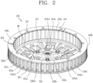
- FIG. 2 illustrating only the rotor 120 excluding the stator 110.
- FIG. 2 is a perspective view of a rotor illustrated in FIG. 1 .
- the rotor 120 may include a rotor frame 121, a bushing 122, a plurality of rotor cores (or rotor core segments) 123a, a plurality of permanent magnets 124, a first end cover 125, a second end cover 126, and a plurality of rivets 127.
- the rotor frame 121 may also be referred to as a rotor housing.
- the rotor frame 121 includes a bushing coupling portion 121a, a spoke 121b, and a circumferential wall or a peripheral wall or base 121c.
- the bushing coupling portion 121a is formed at the center of the rotor frame 121 in a radial direction of the rotor 120.
- the center of the rotor frame 121 corresponds to a position facing the region surrounded by the stator 110.
- the bushing coupling portion 121a is formed to engage with the bushing 122.
- the bushing 122 refers to a part connected to the rotation shaft. One end of the rotation shaft may be coupled to the bushing coupling portion 121a, and the other end may be directly connected to an object to be supplied with a rotational force of the motor 100, such as a drum of the washing machine.
- the bushing 122 may have a shape similar to a hollow cylinder.
- the bushing 122 has threads or bushing coupling portion 122a on an inner circumferential surface of the hollow so as to engage with the rotation shaft.
- the rotation shaft is inserted directly into the bushing 122.
- the rotation shaft and the rotor frame 121 are coupled to each other through the bushing 122.
- the threads may protrude toward the rotation shaft and extend in the axial direction of the rotation shaft.
- the bushing 122 may be coupled to the bushing coupling portion 121a by a fastening member 122b such as a bolt.
- a plurality of fastening members 122b may be provided.
- the plurality of fastening members 122b may be provided at positions spaced apart from each other along a circumference of a hollow formed in the bushing 122.
- the spokes 121b is extended in a radial direction from the bushing coupling portion 121a or extended toward a direction inclined at an acute angle with respect to the radial direction.
- a plurality of spokes 121b are provided therein, and may be arranged around the bushing coupling portion 121a so as to face different directions.
- the spokes 121b are formed at positions covering one side or the other side of the stator 110 in a direction parallel to an axial direction of the rotation shaft. With respect to a direction illustrated above in FIG. 1 , a lower side of the stator 110 corresponds to the one side, and an upper side of the stator 110 corresponds to the other side. In this case, the spoke 121b is formed at a position covering a lower side of the stator 110 from below.
- a heat dissipation hole 121b1 is formed between the plurality of spokes 121b. Heat generated from the motor due to the operation of the motor may be discharged through the heat dissipation hole 121b1.
- the base 121c is formed to support the first end cover 125 or the second end cover 126, which will be described later, in a direction parallel to an axial direction of the rotation shaft.
- a circumference of the base 121c may be the same as that of the first end cover 125 or that of the second end cover 126.
- the base 121c is formed along an outer circumference of the spoke 121b in a circumferential direction.
- the base 121c may be understood as a ring formed on an outer edge of the spokes 121b.
- an inner end of the base 121c may be understood as being connected to an outer end of the plurality of spokes 121b along a circumferential direction.
- a step (HD) may be formed between the base 121c and the spokes 121b.
- the plurality of rotor core segments 123a and the stator 110 may be arranged to face each other in a radial direction of the rotor 120 by the step (HD).
- the plurality of permanent magnets 124 and the stator 110 may be arranged to face each other in a radial direction of the rotor 120 by the step (HD).
- the base 121c is formed to support the first end cover 125 or the second end cover 126, which will be described later.
- the base 121c and the first end cover 125 may be formed in annular shapes corresponding to each other.
- the base 121c and the second end cover 126 may also be formed in annular shapes corresponding to each other.
- the bushing coupling portion 121a, the spokes 121b and the base 121c should be understood as names indicating different positions of the rotor frame 121, and should not be understood as a combination of different parts.
- the plurality of rotor core segments 123a are arranged on an outer side of the stator 110 so as to be spaced apart from each other along a circumferential direction of the rotor 120.
- the plurality of rotor core segments 123a are formed by stacking a plurality of single electric steel sheets (magnetic bodies) along a direction parallel to an axial direction of the rotation shaft.
- the single electrical steel sheets may have the same shape. However, at least one electric steel sheet disposed at a lower end and at least one electric steel sheet disposed at an upper end with respect to the stacking direction of the electric steel sheets may be larger than other electric steel sheets to support the permanent magnet 124.
- the rotor core segment 123a performs the role of concentrating a force of the permanent magnets 124.
- the force of the permanent magnet 124 is concentrated on the rotor core segment 123a, the performance of the motor 100 dramatically increases.
- the plurality of rotor core segments 123a are connected to each other, the efficiency of the motor 100 is reduced. Therefore, in order to improve the efficiency of the motor 100, the plurality of rotor core segments 123a may be spaced from each other.
- the plurality of permanent magnets 124 are alternately arranged one by one with the plurality of rotor core segments 123a along a circumferential direction of the rotor 120.
- the circumferential direction of the rotor 120 refers to a circumferential direction of the base 121c.
- the plurality of permanent magnets 124 and the plurality of rotor core segments 123a are alternately arranged one by one, and thus the same number of permanent magnets 124 and the rotor core segments 123a are provided in the rotor 120.
- the plurality of rotor core segments 123a and the plurality of permanent magnets 124 are exposed to inner and outer sides of the rotor 120 in a radial direction of the rotor 120.
- the inner side of the rotor 120 refers to a position at which the bushing 122 is installed.
- the outer side of the rotor 120 refers to a position corresponding to an opposite side of the bushing 122 in a radial direction with respect to the plurality of rotor core segments 123a or the plurality of permanent magnets 124.
- Each of the plurality of rotor core segments 123a and the plurality of permanent magnets 124 has a first end and a second end in a direction parallel to an axial direction of the rotation shaft.
- the first end refers to a lower end of the plurality of rotor core segments 123a, and a lower end of the plurality of permanent magnets 124, with respect to a direction illustrated in FIG. 2 .
- ordinal numbers, first and second do not have a special meaning in the ordinal number in that they are added to distinguish each other. Therefore, the upper end of the plurality of rotor core segments 123a and the upper end of the plurality of permanent magnets 124 may be also referred to as a first end.
- the first end cover 125 is formed to cover a first end of the plurality of permanent magnets 124 and a first end of the plurality of rotor core segments 123a in a direction parallel to an axial direction of the rotation shaft.
- the first end cover 125 is formed in an annular shape along a circumferential direction of the rotor 120.
- the first end of the plurality of rotor core segments 123a and the first end of the plurality of permanent magnets 124 refer to the respective lower ends thereof in FIG. 2 . Accordingly, the first end cover 125 is formed to cover a lower end of the plurality of permanent magnets 124 and a lower end of the plurality of rotor core segments 123a in a direction parallel to an axial direction of the rotation shaft.
- the first end cover 125 is disposed between the plurality of rotor core segments 123a and the base 121c in a direction parallel to an axial direction of the rotation shaft. Furthermore, since the plurality of rotor core segments 123a and the plurality of permanent magnets 124 are alternately arranged along the same circumference, it may also be understood that the first end cover 125 is disposed between the plurality of permanent magnets 124 and the base 121c in a direction parallel to an axial direction of the rotation shaft.
- the second end cover 126 is formed to cover a second end of the plurality of permanent magnets 124 and a second end of the plurality of rotor core segments 123a in a direction parallel to an axial direction of the rotation shaft.
- the second end cover 126 is formed in an annular shape along a circumferential direction of the rotor 120.
- the second end of the plurality of rotor core segments 123a and the second end of the plurality of permanent magnets 124 refer to the respective upper ends thereof in FIG. 2 . Accordingly, the second end cover 126 is formed to cover an upper end of the plurality of rotor core segments 123a and an upper end of the plurality of permanent magnets 124 in a direction parallel to an axial direction of the rotation shaft.
- the second end cover 126 is disposed so as to be spaced apart from the first end cover 125 in a direction parallel to an axial direction of the rotation shaft.
- the first end cover 125 and the second end cover 126 are disposed at positions facing each other in an axial direction of the rotation shaft.
- the other components except for the rotor frame 121 may be symmetrical to each other with respect to a plane perpendicular to an axial direction of the rotation shaft.
- the rotor frame 121 may be coupled to the second end cover 126.
- the first end cover 125 has rotor core coupling protrusions 125a1, 125b1, 126a1 protruded toward the second end cover 126.
- a plurality of rotor core coupling protrusions 125a1, 125b1 of the first end cover 125 are provided, and the plurality of rotor core coupling protrusions 125a1, 125b1 are formed at positions spaced apart from each other along a circumferential direction of the first end cover 125.
- the second end cover 126 also has a rotor core coupling protrusion 126a1 protruded toward the first end cover 125.
- a plurality of rotor core coupling protrusions 126a1, 126b1 of the second end cover 126 are provided, and the plurality of rotor core coupling protrusions 126a1 are formed at positions spaced apart from each other along a circumferential direction of the second end cover 126.
- Each of the plurality of rotor core segments 123a has a rotor core slot 123a5 formed along a direction parallel to an axial direction of the rotation shaft.
- the rotor core slot 123a5 is formed at an outer end of each rotor core segment 123a. Furthermore, the rotor core coupling protrusions 125a1, 125b1 of the first end cover 125 and the rotor core coupling protrusion 126a1 of the second end cover 126 are inserted into the rotor core slot 123a5 of the rotor core segment 123a along a direction parallel to an axial direction of the rotation shaft.
- the first end cover 125 is also formed by annular sector or circular arc shaped plates 125a, 125b.
- the plates 125a, 125b forming the first end cover 125 are arranged along a circumferential direction of the rotor 120.
- a first split point (SP1) is formed each between the plates 125a, 125b of the first end cover 125 along a circumferential direction of the rotor 120.
- the second end cover 126 is also formed by annular sector or arc shaped plates 126a, 126b, 126c.
- the plates 126a, 126b, 126c are arranged along a circumferential direction of the rotor 120.
- a second split point (SP2) is formed each between the plates 126a, 126b, 126c of the second end cover 126 along a circumferential direction of the rotor 120.
- FIG. 2 when three plates 126a, 126b, 126c are arranged on a circumference of the rotor 120 about the rotation shaft, each plate 126a, 126b, 126c is shown in an annulus sector or circular arc shape having a center angle of 120°.
- three second split points (SP2) are formed along a circumferential direction of the rotor 120.
- first end cover 125 and the second end cover 126 are not formed by the plates 125a, 125b, 126a, 126b, 126c but formed as a single member, then an excessive centrifugal force acts on the first end cover 125 and the second end cover 126.
- the first end cover 125 and the second end cover 126 may include a plurality of plates 125a, 125b, 126a, 126b, 126c, a centrifugal force acting on only a single member may be dispersed on the plurality of plates 125a, 126a, 126b, 126c.
- the rivet 127 is formed to engage the first end cover 125, the rotor core block 123, the second end cover 126, and the base 121c of the rotor frame 121. One end of the rivet 127 may be exposed through the second end cover 126. A more detailed coupling structure of the rivet 127 will be described later.
- FIG. 3 illustrates one rotor core block 123, a plurality of permanent magnets 124 coupled to the one rotor core block 123, two first end covers 125, one second end cover 126, a rotor frame 121, and four rivets 127 to visually check an assembly structure of the rotor illustrated in FIG. 2 .
- the rotor 120 may include a plurality of rotor core blocks 123.
- the rotor core block 123 refers to a single unit member formed by gathering a plurality of rotor core segments 123a. Therefore, one rotor core block 123 is provided with a plurality of rotor core segments 123a. Furthermore, the plurality of rotor core segments 123a are connected to each other by a bridge, which will be described later, to form a rotor core block 123 as a unit member.
- the rotor 120 may include a plurality of rotor core blocks 123. For example, when the number of rotor core segments 123a included in one rotor core block 123 is eight as shown in FIG. 3 , six rotor core blocks 123 may be arranged in total to make the rotor 120 including 48 rotor core segments 123a and 48 permanent magnets 124.
- the plurality of rotor core blocks 123 may be arranged to be spaced apart from each other along a circumferential direction of the rotor 120.
- the plurality of permanent magnets 124 are arranged one by one each between the two rotor core segments 123a along a circumferential direction of the rotor 120.
- the plurality of rotor core segments 123a and the plurality of permanent magnets 124 are alternately arranged one by one.
- the annular sector or arc shaped plates 125a, 125b forming the first end cover 125 and the plates 126a forming the second end cover 126 are arranged to be staggered from each other in a circumferential direction of the rotor.
- a first split point (SP1) is formed each between the plates 125a, 125b of the first end cover 125
- a second split point (SP2) is formed each between the plates 126a of the second end cover 126, wherein the first split point (SP1) and the second split point (SP2) are alternately formed in a circumferential direction of the rotor 120.
- the plates 125a, 125b are offset from the plates 126a, 126b in the circumferential direction of the rotor 120.
- the first split point (SP1) and the second split point (SP2) are formed at positions which do not overlap with each other in a direction parallel to an axial direction of the rotation shaft.
- first and second split points (SP1, SP2) may be a cause for decreasing the strength of the coupling structure of the rotor 120.
- first split point (SP1) and the second split point (SP2) are formed at positions that do not overlap with each other in a direction parallel to an axial direction of the rotation shaft, the strength of the coupling structure of the rotor 120 may be suppressed from decreasing.
- the rotor core coupling protrusions 125a1, 125b1 of the first end cover 125 may be arranged in two columns (L11, L12) along a radial direction of the rotor 120.
- first column (L11) relatively closer to the rotation shaft is formed with not only the rotor core coupling protrusions 125a1, 125b1 but also the rivet coupling holes 125a2, 125b2.
- the plurality of rotor core coupling protrusions 125a1, 125b1 and one rivet coupling hole 125a2, 125b2 are alternately formed in the first column (L11) along a circumferential direction of the first end cover 125.
- only the rotor core coupling protrusions 125a1, 125b1 are formed in the second column (L12) relatively far from the rotation shaft.
- the rivet coupling hole 125b2 may be formed only in the second column (L12), and may also be formed in both the first column (L11) and the second column (L12). Furthermore, the rivet coupling hole 125b2 may alternatively be formed in the first column (L11) and the second column (L12) along a circumferential direction of the rotor 120.
- the plurality of rotor core coupling protrusions 125a1, 125b1 and the plurality of rivet coupling holes 125b2 are formed along a circumferential direction of the first end cover 125.
- the shape of the second end cover 126 is also substantially the same as or similar to that of the first end cover 125.
- a plurality of cover coupling holes 121c1 and a plurality of rivet coupling holes 121c2 are formed in the base 121c of the rotor frame 121.
- the cover coupling holes 121c1 of the rotor frame 121 may be arranged in two columns (L31, L32) along a radial direction of the rotor frame 121.
- the two columns (L31, L32) denote a first column (L31) relatively closer to the rotation shaft and a second column L32 relatively far from the rotation shaft.
- the cover coupling holes 121c1 of the first column (L31) and the second column (L32) are formed on the same line in a radial direction of the rotor frame 121.
- the rivet coupling holes 121c2 of the rotor frame 121 are formed on the same circumference as the first column (L41) of the cover coupling holes 121c1.
- the rivet coupling holes 121c2 may be alternately formed with the cover coupling holes 121c1 along a circumferential direction of the base 121c.
- the plurality of cover coupling holes 121c1 and the plurality of rivet coupling holes 121c2 formed in the first column (L31) are formed and alternately arranged at positions spaced apart from each other along a circumferential direction of the base 121c.
- the rivet coupling holes 121c2 may also be formed in the second column (L32).
- the rivets 127 are extended along a direction parallel to an axial direction of the rotation shaft.
- the rivet 127 passes through the first end cover 125, the rotor core segment 123a, the second end cover 126, and the base 121c of the rotor frame 121 to couple parts constituting the rotor 120 to each other.
- FIG. 4 is an exploded perspective view of the rotor 120.
- FIG. 5 is a partially enlarged view illustrating the exploded perspective view of the rotor 120.
- the bushing 122 is seated in the bushing coupling portion 121a of the rotor frame 121 in an axial direction of the rotation shaft.
- a plurality of fastening member coupling holes 122c are formed at positions spaced apart from each other around a hollow formed in the bushing 122.
- a plurality of fastening member coupling holes 121a1 are also formed at positions spaced from each other around a hollow formed in the bushing coupling portion 121a.
- the fastening member coupling holes 122c of the bushing 122 and the fastening member coupling holes 121a1 of the bushing coupling portion 121a are formed at positions facing each other in a direction parallel to an axial direction of the rotation shaft.
- the fastening member 122b is fastened to the fastening member coupling hole 122c of the bushing 122 and the fastening member coupling hole 121a1 of the bushing coupling portion 121a in a direction parallel to an axial direction of the rotation shaft.
- the fastening member 122b may be formed of a bolt or the like, and a nut corresponding to the bolt may be provided on an inner or outer side of the rotor frame 121.
- each rotor core segment 123a includes a body 123a1, a head 123a2, a core protrusion 123a3, a rotor core hole 123a4, a rotor core slot 123a5, and a mac 123a6.
- the body 123a1 corresponds to a portion occupying the largest volume of the rotor core segment 123a.
- the body 123a1 is disposed to face the permanent magnet 124 in a circumferential direction of the rotor 120. Both side surfaces of the body 123a1 are disposed to face a first working surface 124a of the permanent magnet 124, and are in surface contact with the first working surface 124a.
- the plurality of rotor core segments 123a are arranged along a side face of the hollow cylinder.
- a portion located on a circumference corresponding to an inner diameter of the cylinder corresponds to an inner end of the body 123a1.
- an outer end of the body 123a1 indicates a portion formed with the core protrusion 123a3 and the rotor core slot 123a5 to be described later.
- the inner end of the body 123a1 is disposed to face the stator 110 at a position spaced apart from the stator 110.
- a width of the body 123a1 with respect to a circumferential direction of the rotor 120 may be formed to gradually increase from the inner end to the outer end of the body 123a1. For instance, a linear distance between both side surfaces of the body 123a1 in a circumferential direction of the rotor 120 gradually increases from the inner end to the outer end of the body 123a1.
- the second circumference is larger than the first circumference.
- the first working surface 124a of the permanent magnet 124 is extended along a direction parallel to a radial direction of the rotor 120, an area based on a difference between the first circumference and the second circumference may be filled by the rotor core segment 123a.
- a width of the body 123a1 with respect to a circumferential direction of the rotor 120 to fill the area is formed to gradually increase from the inner end to the outer end.
- the plurality of rotor core segments 123a and the plurality of permanent magnets 124 in a circumferential direction of the rotor 120 may be arranged without a hollow space.
- the outer end of the rotor core segment 123a is disposed radially outward of the inner end of the rotor core segment 123a.
- the head 123a2 is protruded from an inner end of the body 123a1 to both sides thereof toward a circumferential direction of the rotor 120.
- a single rotor core segment 123a is formed with two heads 123a2.
- Two heads 123a2 are formed at positions facing an inner surface of the permanent magnet 124 with respect to a single permanent magnet 124.
- the two heads 123a2 restrict the movement of the permanent magnet 124 toward the rotation shaft.
- Either one of the two heads 123a2 corresponds to a head 123a2 of the rotor core segment 123a disposed on one side of the permanent magnet 124, and the other one corresponds to a head 123a2 of the rotor core segment 123a disposed on the other side of the permanent magnet 124.
- the core protrusion 123a3 is protruded from an outer end of the body 123a1.
- the core protrusion 123a3 is extended in two sections toward directions away from each other to form the rotor core slot 123a5.
- One rotor core segment 123a is formed with two core protrusions 123a3.
- the two core protrusions 123a3 are protruded toward a direction inclined to a radial direction of the rotor 120. Both side surfaces of the core protrusion 123a3 are arranged to face the second working surface 124b of the permanent magnet 124, and are in surface contact with the second working surface 124b.
- Two core protrusions 123a3 are formed at a position facing an outer surface of one permanent magnet 124 with respect to the permanent magnet 124.
- the two core protrusions 123a3 restrain the permanent magnet 124 that is about to move toward a direction away from the rotation shaft due to a centrifugal force during the operation of the motor 100.
- Either one of the two core protrusions 123a3 corresponds to a core protrusion 123a3 of the rotor core segment 123a disposed on one side of the permanent magnet 124, and the other one corresponds to a core protrusion 123a3 of another rotor core segment 123a disposed on the other side of the permanent magnet 124.
- the rotor core hole 123a4 is formed in the body 123a1.
- the rotor core hole 123a4 is open toward a direction parallel to an axial direction of the rotation shaft (in a vertical direction in FIGS. 4 and 5 ).
- the rotor core hole 123a4 is formed between inner and outer ends of the body 123a1 in a radial direction of the rotor 120.
- the rotor core slot 123a5 is formed at an outer end of the body 123a1, and thus the rotor core hole 123a4 is formed between an inner end of the body 123a1 and the rotor core slot 123a5 in a radial direction of the rotor 120.
- the rotor core slot 123a5 may be defined between the two core protrusions 123a3 in a circumferential direction of the rotor 120. It will be understood that the rotor core slot 123a5 has a shape recessed toward the body 123a1 between the two core protrusions 123a3 with respect to a radial direction of the rotor 120. A circumference of the rotor core slot 123a5 is formed as a curved surface having a cross section of a semicircle or a shape similar to a semicircle.
- the rotor core hole 123a4 and the rotor core slot 123a5 are a region that accommodates the rotor core coupling protrusions 125a1, 125b1, 125c1 of the first end cover 125 and the rotor core coupling protrusions 126a1, 126b1k, 126c1 of the second end cover 126, and the rivet 127.
- the rotor core coupling protrusions 125a1, 125b1, 125c1 formed in the first column (L11) in the first end cover 125 and the rotor core coupling protrusions 126a1, 126b1, 126c1 formed in the first column (L21) in the second end cover 126 are inserted into the holes.
- the rotor core coupling protrusions 125a1, 125b1, 125c1 formed in the second column (L12) in the first end cover 125 and the rotor core coupling protrusions 126a1, 126b1, 126c1 formed in the second column (L22) in the second end cover 126 are inserted into the rotor core slots 123a5.
- the rivets 127 are inserted into some rotor core holes 123a4.
- the respective parts When the rotor 120 is to be manufactured through the assembly of parts constituting the rotor 120, the respective parts may be seated in place.
- the coupling structure of the rotor core coupling protrusions 125a1, 125b1, 125c1, 126a1, 126b1, 126c1 and the rotor core holes 123a4 and the coupling structure of the rotor core coupling protrusions 125a1, 125b1, 125c1, 126a1, 126b1, 126c1 and the rotor core slots 123a5 perform the role of an assembly guide for seating parts in place.
- the mac 123a6 may be defined at each single electrical steel sheet constituting each rotor core segment 123a.
- the mac 123a6 may protrude from one surface of each electrical steel sheet, and have a protruding shape that is recessed from the other surface at the same position as the protruding position.
- a plurality of macs 123a6 may be formed around the rotor core holes 123a4.
- the mac 123a6 is a structure or a mating part for aligning and stacking single electrical steel sheets at positions corresponding to each other.
- a plurality of electric steel sheets are stacked in such a manner that either one protruded mac 123a6 between the two electric steel sheets disposed to face each other is inserted into the other recessed mac 123a6, the electrical steel sheets constituting the rotor core segment 123a may be aligned with each other.
- each rotor core segment 123a The inner ends of each rotor core segment 123a are protruded to both sides in a circumferential direction. In addition, a circumferential width of each rotor core segment 123a is gradually widened toward the outer end. This type of inner and outer ends prevent the permanent magnet 124 from being radially released from between the two rotor core segments 123a.
- the inner ends of the rotor core segment 123a are disposed so as to face the stator 110 while covering the stator 110.
- the outer ends of the rotor core segment 123a are divided into two sections, and a rotor core slot 123a5 as described above is formed between the two sections.
- the rotor core slot 123a5 is formed in a recessed shape toward an inner end from an outer end of the rotor core segment 123a.
- the plurality of rotor core segments 123a and the plurality of permanent magnets 124 are alternately arranged one by one, and thus, the plurality of rotor core segments 123a are spaced from each other along a circumferential direction of the rotor 120. However, in one rotor core block 123, the plurality of rotor core segments 123a are connected to each other by a bridge 123b.
- the bridge 123b is formed to connect the rotor core segments 123a provided in the rotor core block 123 with each other.
- the bridge 123b may be formed to connect the heads 123a2 of two adjacent rotor core segments 123a to each other or connect the core protrusions 123a3 of the two rotor core segments 123a to each other.
- the bridge 123b is formed at an inner or outer end of the rotor core segment 123a to connect the plurality of rotor core segments 123a to each other.
- the bridge 123b is extended in a circumferential direction along the inner or outer ends of the plurality of rotor core segments 123a.
- the plurality of rotor core segments 123a spaced from each other due to the alternate arrangement with the permanent magnets 124 are connected to each other by the bridge 123b to form a rotor core block 123 as a unit member.
- the number of bridges 123b is one less than or greater than that of rotor core segments 123a provided in one rotor core block 123. For instance, when the number of the rotor core segments 123a provided in one rotor core block 123 is eight, at least seven bridges 123b may be provided in the one rotor core block 123.
- Each permanent magnet 124 has a first working surface 124a and a second working surface 124b.
- the magnetic field lines of the permanent magnet 124 are generated from the first working surface 124a and the second working surface 124b.
- the first working surface 124a corresponds to the largest surface of the permanent magnet 124.
- the first working surface 124a faces a circumferential direction of the rotor 120.
- the first working surface 124a may be parallel to a radial direction of the rotor 120.
- the first working surface 124a faces a side surface of the body 123a1 in a circumferential direction of the rotor 120.
- the first working surface 124a is in surface contact with a side surface of the body 123a1.
- the second working surface 124b forms a boundary at an obtuse angle with the first working surface 124a.
- the second working surface 124b may be inclined to a radial direction of the rotor 120.
- a direction toward the rotation shaft may be referred to as an inner direction of the rotor 120
- a direction away from the rotation shaft may be referred to as an outer direction of the rotor 120.
- the second working surface 124b is formed in an outer direction of the rotor 120 compared to the first working surface 124a. That is, the second working surface 124b may be disposed radially outward of the first working surface 124a.
- the first working surface 124a and the second working surface 124b may define an obtuse angle at an interface or boundary, and an edge may be located at the boundary between the first working surface 124a and the second working surface 124b. The edge may extend parallel to an axial direction of the rotation shaft.
- a width of the permanent magnet 124 based on a circumferential direction of the rotor 120 gradually decreases from a boundary between the first working surface 124a and the second working surface 124b to an outer end of the permanent magnet 124.
- An outer end of the permanent magnet 124 being gradually decreased by the second working surface 124b corresponds to two gradually widening core protrusions 123a3 of the rotor core segment 123a.
- the first end cover 125 has a first surface and a second surface.
- the first surface refers to a surface facing the base 121c of the rotor frame 121.
- the second surface refers to a surface facing the plurality of rotor core segments 123a and the plurality of permanent magnets 124.
- a rotor frame coupling protrusion 125b3 is formed on the first surface of the first end cover 125.
- the rotor frame coupling protrusion 125b3 is protruded from the first surface of the first end cover 125 toward the base 121c of the rotor frame 121.
- the rotor frame coupling protrusion 125b3 is formed at a position facing the cover coupling hole 121c1 of the rotor frame 121.
- a plurality of rotor frame coupling protrusions 125b3 may be provided, and the plurality of rotor frame coupling protrusions 125b3 may be arranged in two rows (L41, L42, see FIG. 9A ) along a circumferential direction of the first end cover 125.
- the two columns (L41, L42) denote a first column (L41) relatively closer to the rotation shaft and a second column (L42) relatively far from the rotation shaft.
- the rotor frame coupling protrusion 125b3 of the first column (L41) and the rotor frame coupling protrusion 125b3 of the second column (L42) are formed on the same line in a radial direction of the rotor frame 121.
- the first end cover 125 is formed with rivet coupling holes 125a2, 125b2, 125c2.
- the rivet coupling holes 125a2, 125b2, 125c2 are open toward a direction parallel to an axial direction of the rotation shaft.
- a plurality of rivet coupling holes 125a2, 125b2, 125c2 are formed on the first end cover 125, and the plurality of rivet coupling holes 125a2, 125b2, 125c2 are spaced apart from each other in a circumferential direction.
- the rivet coupling holes 125a2, 125b2, 125c2 of the first end cover 125 may be formed in the first column (L11).
- the second end cover 126 is also formed with rivet coupling holes 126a2, 126b2, 126c2 at positions corresponding to the rivet coupling holes 125a2, 125b2, 125c2 of the first end cover 125.
- the rivet coupling holes 125a2, 125b2, 125c2 of the first end cover 125 and the rivet coupling holes 126a2, 126b2, 126c2 of the second end cover 126 correspond to each other in a direction parallel to an axial direction of the rotation shaft.
- the riveting coupling holes 125a2, 125b2, 125c2 of the second end cover 126 may also be formed in the first column (L21).
- the rivet coupling holes 121c2 are also formed on the base 121c of the rotor frame 121 at positions corresponding to the rivet coupling holes 125a2, 125b2, 125c2 of the first end cover 125 and the rivet coupling holes 126a2, 126b2, 126c2 of the second end cover 126. Similar to the above description, the corresponding direction is a direction parallel to an axial direction of the rotation shaft.
- the rivet coupling holes 121c2 of the rotor frame 121 may also be formed in the first column (L31).
- the rivets 127 sequentially pass through the rivet coupling holes 126a2, 126b2, 126c2 of the second end cover 126, the rotor core holes 123a4 of the rotor core segment 123a, the rivet coupling holes 125a2, 125b2, 125c2 of the first end cover 125, and the rivet coupling holes 121c2 of the rotor frame 121.
- the first end 127a or the second end 127b of the rivet 127 is machined to be larger than the holes after the rivet 127 sequentially passes through the holes, parts constituting the rotor 120 are coupled to each other.
- FIG. 6A is a perspective view showing an example rotor core block 123.
- FIG. 6B is an exploded perspective view showing the example rotor core block 123.
- the rotor core block 123 is formed by stacking a plurality of electrical steel sheets 123', 123".
- the rotor core block 123 is provided with a plurality of rotor core segments 123a. Since the rotor core block 123 is formed by stacking a plurality of electrical steel sheets 123', 123", the rotor core segment 123a is also formed by stacking a plurality of electrical steel sheets 123', 123".
- the plurality of rotor core segments 123a provided in one rotor core block 123 are arranged along a circumferential direction of the rotor 120.
- the plurality of rotor core segments 123a are partially spaced and partially connected along a circumferential direction of the rotor 120.
- the rotor core block 123 For a partial separation between the rotor core segments 123a, the rotor core block 123 includes first type electrical steel sheets 123'. In addition, for a partial connection between the rotor core segments 123a, the rotor core block 123 includes second type electrical steel sheets 123".
- the plurality of electrical steel sheets 123', 123" stacked to form the rotor core block 123 denote the first type electrical steel sheets 123' and the second type electrical steel sheets 123".
- the first type electrical steel sheet 123' includes a body 123a1, a head 123a2, a core protrusion 123a3, a rotor core hole 123a4, a rotor core slot 123a5, and a mac 123a6.
- the second type electrical steel sheet 123" includes a body 123a1, a head 123a2, a core protrusion 123a3, a rotor core hole 123a4, a rotor core slot 123a5, a mac 123b6, and bridges 123b1, 123b2.
- only one body 123a1 is provided for each first type electrical steel sheet 123', while a plurality of bodies 123a1 are provided for the second type electrical steel sheet 123".
- the plural number is equal to the number of rotor core segments 123a provided in the rotor core block 123.
- the plurality of bodies 123a1 provided in the second type electrical steel sheet 123" are connected to each other by the head 123a2 and the bridges 123b1, 123b2.
- the body 123a1 of the first type electrical steel sheet 123' and the body 123a1 of the second type electrical steel sheet 123" are stacked on each other to form the body 123a1 of the rotor core segment 123a.
- the body 123a1 of the first type electrical steel sheet 123' and the body 123a1 of the second type electrical steel sheet 123" form the body 123a1 of the rotor core segment 123a, and the plurality of bodies 123a1 formed as described above are spaced from each other along a circumferential direction of the rotor 120 to form a permanent magnet arrangement slot (MS) each therebetween.
- MS permanent magnet arrangement slot
- the rotor core segment 123a having a height of 39 mm is formed by the first type electrical steel sheet 123' and the second type electrical steel sheet 123" having a thickness of 0.5 mm in a direction parallel to an axial direction of the rotation shaft, a total of 78 sheets of the first type electrical steel sheets 123' and the second type electrical steel sheets 123" may be stacked.
- the first type electrical steel sheets 123' and the second type electrical steel sheets 123" are distinguished from each other by their shapes.
- the bridges 123b1, 123b2 are not provided in the first type electrical steel sheet 123' while the bridges 123b1, 123b2 are provided in the second type electrical steel sheet 123".
- the bridges 123b1, 123b2 provided in the second type electrical steel sheet 123" refer to a configuration in which the plurality of rotor core segments 123a provided in one rotor core block 123 are connected to each other.
- the first type electrical steel sheets 123' and the second type electrical steel sheets 123" are stacked along a direction parallel to an axial direction of the rotation shaft so as to form the rotor core segment 123a.
- a plurality of first type electrical steel sheets 123' are provided.
- a single or a plurality of second type electrical steel sheets 123" are provided.
- the plurality first type electrical steel sheets 123' are stacked along a direction parallel to an axial direction of the rotation shaft so as to be in close contact with each other in the axial direction of the rotating shaft.
- the first type electrical steel sheets 123' are disposed apart from each other in a circumferential direction of the rotor 120.
- the first type electrical steel sheets 123' constituting one rotor core segment 123a are in close contact with each other, while the first type electrical steel sheets 123' constituting different rotor core segments 123a are spaced apart from each other. Since the rotor core segments 123a are spaced apart from each other in a circumferential direction of the rotor 120, the plurality of rotor core segments 123a may also be alternately arranged one by one with the plurality of permanent magnets.
- the second type electrical steel sheets 123" are stacked together with the first type electrical steel sheets 123' to form a plurality of rotor core segments 123a. At least one second type electrical steel sheet 123" may be provided for each rotor core block 123, and a plurality of second type electrical steel sheets 123" may be provided.
- the second type electrical steel sheet 123" may be disposed on the first type electrical steel sheets 123', or may be stacked below and/or above the first type electrical steel sheets 123' on the basis of the stacking direction of the first type electrical steel sheets 123'.
- the plurality of rotor core segments 123a are not completely separated from each other in a circumferential direction of the rotor 120, but connected to each other through the bridges 123b1, 123b2 of the second type electrical steel sheets 123".
- the bridges 123b1, 123b2 may be formed on at least one of an inner end and an outer end of the second type electrical steel sheet 123".
- the inner end of the second type electrical steel sheet 123" refers to between the two heads 123a2, and the outer end thereof refers to between the two core protrusions 123a3.
- an inner end of the second type electrical steel sheet 123" may be referred to as an inner end of the rotor core segment 123a, furthermore, an inner end of the rotor core block 123. The same applies to an outer edge thereof.
- FIGS. 6A and 6B illustrate a configuration in which a bridge is formed on the head 123a2, which is an inner end of the second type electrical steel sheet 123". Furthermore, in FIGS. 6A and 6B , the second type electrical steel sheet 123" is stacked on the lower and upper ends of the plurality of first type electrical steel sheets 123'.
- the plurality of bridges 123b1, 123b2 are formed at an inner end of the plurality of rotor core segments 123a.
- Each of the bridges 123b1, 123b2 is protruded on both sides from an inner end of each rotor core segment 123a and connected to an inner end of another adjacent rotor core segment 123a.
- Each of the plurality of bridges 123b1, 123b2 is formed to connect the first or second ends of two adjacent rotor core segments 123a located closer to each other among the plurality of rotor core segments 123a provided in the rotor core block 123.
- the first and second ends is based on a direction parallel to an axial direction of the rotation shaft.
- the first ends of the rotor core segments 123a are lower ends of the rotor core segments 123a with respect to the axial direction
- the second ends of the rotor core segments 123a are upper ends of the rotor core segments 123a with respect to the axial direction.
- the plurality of bridges 123b1, 123b2 may include a first bridge 123b1 and a second bridge 123b2.
- the first bridge 123b1 and the second bridge 123b2 may be disposed at positions spaced from each other in an axial direction of the rotation shaft.
- the first bridge 123b1 may connect the first ends (e.g., lower ends) of the plurality of rotor core segments 123a to each other
- the second bridge 123b2 may connect the second ends (e.g., upper ends) of the plurality of rotor core segments 123a to each other.
- the first bridge 123b1 and the second bridge 123b2 may not necessarily provided at each end.
- first bridge 123b1 and the second bridge 123b2 may be formed at a position spaced from each end in a direction parallel to an axial direction of the rotation shaft.
- at least one of the first bridge 123b1 or the second bridge 123b2 may be disposed at a position between the first end and the second end of the rotor core segment 123a.
- a third bridge, a fourth bridge, and the like which have similar shapes as the first and second bridges 123b1 and 123b2, may be added at positions corresponding to any of the first end and the second end of the rotor core segment 123a.
- a third bridge, a fourth bridge, and the like may be added at positions between the first end and the second end of the rotor core segment 123a.
- each of the bridges 123b1, 123b2 may not completely cover each permanent magnet 124 that is inserted between the two rotor core segments 123a, but may cover only a part(s) of the permanent magnet 124.
- each of the bridges 123b1, 123b2 may cover only the first end and/or the second end of each permanent magnet 124, and may expose the remaining portion of the permanent magnet 124. This is because the first bridge 123b1 and the second bridge 123b2 are formed at positions spaced from each other in a direction parallel to an axial direction of the rotation shaft.
- first bridge 123b1 and the second bridge 123b2 are spaced apart from each other, an opening is formed for each region defined by inner ends of the plurality of rotor core segments 123a, and the first bridge 123b1 and the second bridge 123b2. Furthermore, the plurality of permanent magnets 124 are exposed in a radial direction of the rotor 120 through the openings.
- the motor 100 may include the rotor core segments 123a that are completely split (separated) from each other.
- the completely split structure of the rotor core segment 123a may cause a decrease in the structural strength of the rotor 120. If the bridges 123b1, 123b2 completely cover the permanent magnets 124, then the structural strength of the rotor 120 may be improved. However, the efficiency of the motor 100 may be rapidly reduced. As described above, the efficiency of the motor 100 and the structural strength of the rotor 120 may be in a trade-off relationship.
- the bridges 123b1, 123b2 do not completely cover the permanent magnets 124, and thus the structural strength of the rotor 120 may be improved at some expense of the efficiency of the motor 100.
- the present disclosure is based on the premise that the effect of improving the structural strength of the rotor 120 is greater than the sacrificed efficiency of the motor 100.
- the length and thickness of the bridges 123b1, 123b2 should be set in an appropriate range to reflect the trade-off relationship.
- the thickness of either one of the bridges 123b1, 123b2 in a direction parallel to an axial direction of the rotation shaft may be 2 mm to 5 mm. If the thickness of the second type electrical steel sheet is 0.5 mm, then four to ten second type electrical steel sheets may be stacked.
- the bridges 123b1, 123b2 are provided at lower and upper ends of the rotor core segment 123a in an arbitrary direction parallel to an axial direction of the rotation shaft, four to ten second type electrical steel sheets are stacked at the lower end, and four to ten second type electrical steel sheets are stacked at the upper end.
- the remaining thickness required to form the rotor core segment 123a is stacked by the first type electrical steel sheets.
- a sum of the thicknesses (a) of at least one bridge 123b1, 123b2 arranged in an arbitrary direction parallel to an axial direction of the rotation shaft is ⁇ a
- a height of the rotor core segment 123a is b
- a ratio ( ⁇ a/b) of the two values is 5% to 15%.
- the bridge 123b includes the first bridge 123b1 and the second bridge 123b2
- the sum ( ⁇ a) is equal to the sum of the thickness of the first bridge 123b1 and the thickness of the second bridge 123b2 in a direction parallel to an axial direction of the rotation shaft.
- the thickness of the bridge 123b1 in a direction parallel to an axial direction of the rotation shaft is 1.65 mm to 4.95 mm.
- the plurality of bridges 123b1, 123b2 are provided together in an arbitrary direction parallel to an axial direction of the rotation shaft and the height of the rotor core segment 123a is 33 mm in a direction parallel to the axial direction of the rotation shaft, then the sum of the thicknesses of the plurality of bridges 123b1, 123b2 is 1.65 mm to 4.95 mm.
- the ratio (a/b) is less than 5%, the effect of improving the structural strength is insufficient. In examples, where the ratio (a/b) exceeds 15%, the efficiency of the motor may be excessively reduced.
- the bridges 123b1, 123b2 completely cover the permanent magnets 124, an electromotive force of the motor is reduced by about 20%, but the electromotive force of the motor is reduced only by about 5% in a numerical range of the ratio (a/b) of 5% to 15%. Therefore, there is an effect of improving the back electromotive force by about 15%.
- the width of each of the bridges 123b1, 123b2 in a radial direction of the rotor 120 may be 0.45 mm to 2 mm. If the width of the bridges 123b1, 123b2 is less than 0.45 mm, the effect of improving the structural strength is insufficient. If the width of the bridges 123b1, 123b2 exceeds 2 mm, the efficiency of the motor is excessively reduced.
- FIG. 7A is a perspective view showing an example rotor core block 223.
- FIG. 7B is an exploded perspective view showing the rotor core block 223.
- the plurality of bridges 223b1, 223b2 may be formed at an outer end of the rotor core segment 223a.
- the plurality of bridges 223b1, 223b2 are formed so as to connect protrusions 223a3 formed on two adjacent second type electrical steel sheets 223".
- the plurality of bridges 223b1, 223b2 may be formed between a first end and a second end of the rotor core segment 223a. This structure is more effective in restraining the permanent magnets 124 from being scattered in a radial direction during the high-speed operation of the motor.
- the rotor core block 223 may include a first type electrical steel sheet 223', a body 223a1, a head 223a2, a rotor core hole 223a4, a rotor core slot 223a5, and a mac 223a6. Each of these components may have features similar to those of the rotor core block 123 described above.
- FIG. 8A is a perspective view showing an example rotor core block 323.
- FIG. 8B is an exploded perspective view showing the rotor core block 323.
- the plurality of bridges 323b1, 323b2, 323b3, 323b4 may be alternately formed at an inner end and an outer end of the plurality of rotor core segments 323a.
- some (e.g., bridges 323b1, 323b2) of the plurality of bridges 323b1, 323b2, 323b3, 323b4 may connect the heads 323a2 disposed on two adjacent second type electrical steel sheets 323".
- the other bridges 323b3, 323b4 may connect the protrusions 323a3 disposed at the two adjacent second type electrical steel sheets 323".
- the outer end of the rotor core segment 323a is disposed radially outward of the inner end of the rotor core segment 323a.
- the plurality of bridges 323b1, 323b2, 323b3, 323b4 may be formed at the first and second ends of the rotor core segment 323a, respectively.
- the rotor core block 323 includes a first type electrical steel sheet 323', a body 323a1, a rotor core hole 323a4, a rotor core slot 323a5, and a mac 323a6. Each of these components may have features similar to those of the rotor core block 123 or 223 described above.
- FIGS. 9A through 9E are conceptual views showing a procedure for manufacturing the rotor 200.
- a bushing 222 is seated in a bushing coupling portion 221a.
- the bushing 222 is fastened to the bushing coupling portion 221a by a fastening member 222b.
- Reference numeral 222a corresponds to a thread.
- the plates 225a, 225b constituting a first end cover 225 are seated on the base 221c of the rotor frame 221.
- the seating order of the bushing 222 and the first end cover 225 may be changed or may also be seated at the same time.
- the position of the rotor frame coupling protrusion 225b3 formed on the first end cover 225 is adjusted to be inserted into the cover coupling hole 221c1 formed in the base 221c.
- the plurality of plates 225a and 225b forming the first end cover 225 along a circumference of the base 221c are seated on the base 221c.
- the rotor core block 223 is seated on the first end cover 225.
- the positions of the rotor core coupling protrusions 225a1, 225b1 formed on the first end cover 225 are adjusted to be inserted into the rotor core holes 223a4 and the rotor core slots 223a5 of the rotor core segment 223a.
- One rotor core block 223 may have all the rotor core segments 223a of the rotor 220. In this case, all the rotor core segments 223a are connected by bridges 223b1, 223b2. Alternatively, the plurality of rotor core blocks 223 may be seated along a circumference of the first end cover 225.
- a permanent magnet 224 is inserted each between the two rotor core segments 223a.
- the permanent magnet 224 is inserted in a direction parallel to an axial direction of the rotation shaft.
- the radial movement of the permanent magnet 224 is restricted by an inner end and an outer end of the rotor core segment 223a and the bridges 223b1, 223b2 formed at the inner end or the outer end of the rotor core segment 223a.
- the outer end of the rotor core segment 223a is disposed radially outward of the inner end of the rotor core segment 223a.
- the plates 226a, 226b, 226c constituting the second end cover 226 are seated on the rotor core block 223 and the plurality of permanent magnets 224.
- the positions of the rotor core coupling protrusions 226a1 formed on the second end cover 226 are adjusted to be inserted into the rotor core holes 223a4 and the rotor core slots 223a5 of the rotor core segment 223a.
- the plurality of plates 226a, 226b, 226c forming the second end cover 226 are seated on the rotor core block 223 and the plurality of permanent magnets 224 along a circumference of the rotor 220.
- the rivets 227 are used to couple parts constituting the rotor 220 to each other.
- the rotor 220 passes through rivet coupling holes 226a2, 226b2, 226c2 of the second end cover 226, a rotor core hole 223a4 of the rotor core segment 223a, rivet coupling holes 225a2, 225b2 of the first end cover 225, and a rivet coupling hole 221c2 of the base 221c along a direction parallel to an axial direction of the rotation shaft.
- a first end of the rivet 227 is exposed to the rivet coupling hole 221c2 formed in the base 221c of the rotor frame 221.
- the engagement of the rivet 227 is completed to complete the assembly of the rotor 220.
- FIG. 10 is a concept showing another implementation of the rotor 400.
- Injection molding is a type of method of molding a resin, and refers to a method of cooling and solidifying a molten raw material in a mold at a high pressure to produce a molded article having a shape corresponding to the mold.
- a molded article produced by injection molding is referred to as an injection product.
- Insert injection molding refers to a method of injecting an insert component together with a molten raw material into a mold to produce a molded article.
- the injection product has a shape corresponding to a mold, and is produced while an insert component is integrated with an injection product inside the injection product.
- At least one rotor core block 423 and a permanent magnet 424 are disposed along a circumferential direction in the mold prior to insert injection molding.
- the rotor core block 423 has a plurality of rotor core segments 423a. Accordingly, a plurality of rotor core segments 423a and a plurality of permanent magnets 424 are alternately arranged at predetermined positions of the mold along a predetermined circumference.
- the molten injection material forms a rotor frame 421.
- the rotor frame 421 of the rotor 420 thus manufactured integrates at least one rotor core block 423 and a plurality of permanent magnets 424.
- a portion surrounding the rotor core block 423 and the plurality of permanent magnets 424 in the rotor frame 421 may be referred to as a circumferential wall or a circumferential wall 421d.
- the circumferential wall 421d surrounds first and second ends of the rotor core block 423 in a direction parallel to an axial direction of the rotation shaft, and surrounds first and second ends of the plurality of permanent magnets 424. Furthermore, the circumferential wall 421d surrounds an outer end of the rotor core block 423 and an outer end of the plurality of permanent magnets 424 in a radial direction of the rotor 420.
- An inner pillar 421e is formed at an inner end of the circumferential wall 421d.
- the inner pillar 421e is extended along a direction parallel to an axial direction of the rotation shaft.
- a plurality of inner pillars 421e are provided, and the plurality of inner pillars 421e are formed at positions spaced from each other along an inner end of the circumferential wall 421d.
- the inner pillar 421e is formed in the same direction as the permanent magnet 424 in a radial direction of the rotor frame 421, and disposed closer to the rotation shaft than the permanent magnet 424.
- An opening may be formed each between the two inner pillars 421e, and an inner end of the rotor core segment 423a is exposed through the opening.
- the permanent magnet 424 may be covered by the inner end of the rotor core segment 423a and the inner pillar 421e.
- the first end cover and the second end cover as described above are not required. This is because the circumferential wall 421d of the rotor frame 421 serves as a first end cover and a second end cover.
- a rotor frame hole 421f and a permanent magnet fixing jig hole 421g may be formed to fix parts in the mold during insert injection molding.
- the rotor frame hole 421f is a position where the mold pin has been disposed during insert injection molding for producing the rotor 420 originally. Even though the molten raw material for insert injection molding is filled in the mold, the molten material is only filled above or below the mold pin, and the molten material cannot exist at the position where the mold pin exists. Therefore, as a result of insert injection molding, the rotor frame hole 421f remains.
- the permanent magnet fixing jig hole 421g is formed at one end of the inner pillar 421e.
- the permanent magnet fixing jig holes 421g are formed at positions corresponding to the respective permanent magnets 424 in a radial direction of the rotor frame 421.
- a permanent magnet fixing jig for fixing the plurality of permanent magnets 424 may be formed on a mold for producing the rotor 420.
- the permanent magnet fixing jig closely adheres each of the permanent magnets 424 seated on a mold pin to the mold pin along a direction parallel to an axial direction of the rotation shaft. Therefore, each of the permanent magnets 424 may be fixed along this direction.
- the permanent magnet fixing jig hole 421g remains.
- the position of the permanent magnet 424 may be visually checked from an outer side of the rotor frame 421 through the permanent magnet fixing jig hole 421g since the permanent magnet 424 is visually exposed through the permanent magnet fixing jig hole 421g.
- the bridge 423b is exposed through the permanent magnet fixing jig hole 421g.
- the bridge 423b connects the two rotor core segments 423a across an inner end or an outer end of the permanent magnet 424 and thus may be exposed through the permanent magnet fixing jig hole 421g.
- non-described reference numerals 421a, 421a1, 421b, 421b1 and 421b2 denote a bushing coupling portion, a first reinforcing rib, a spoke, a second reinforcing rib, and a heat dissipation hole, respectively.
- the first reinforcing rib and the second reinforcing rib are respectively protruded from a circumference of the bushing coupling portion and the spoke, thereby improving the structural strength.
- the description of the remaining configuration is replaced with the above description.
- a partially split structure of a rotor core using a bridge may be adopted by breaking away from a completely divided structure of the rotor core, thereby dramatically improving the structural strength of the rotor at some expensed of the efficiency of the motor.
- the partially split structure of the rotor core may reduce the number of parts for manufacturing the rotor compared to the completely split structure, thereby improving the productivity of the motor.
- the first end cover and the second end cover may be configured with a plurality of plates to disperse a centrifugal force applied to the rotor to each plate.
- the plates of the first end cover and the plates of the second end cover may be arranged to be staggered from each other in a direction parallel to an axial direction of the rotation shaft, thereby improving the structural strength of the rotor.
- the first end cover, the second end cover, the rotor core, and the coupling structure of various protrusions and holes, protrusion and grooves formed in the rotor fame may be used, thereby guiding each part to be located in place as well as maintaining a strong coupling force of the manufactured rotor during the assembly of the rotor.
- the rotor may include plates of the same shape constituting the first end cover, plates of the same shape constituting the second end cover, rotor core blocks of the same shape, and the like, thereby securing dimensional stability subsequent to the assembly process of the rotor as well as reducing a performance variation during the mass production of the motor.
Landscapes
- Engineering & Computer Science (AREA)
- Power Engineering (AREA)
- Permanent Field Magnets Of Synchronous Machinery (AREA)
- Iron Core Of Rotating Electric Machines (AREA)
Claims (16)
- Moteur, comprenantun stator (110) ; etun rotor (120) disposé de manière rotative sur un côté intérieur du stator ou sur un côté extérieur du stator,où le rotor (120) comprendun bloc de noyau de rotor (123) comprenant une pluralité de segments de noyau de rotor (123a) disposés dans la direction circonférentielle du rotor, chacun des segments de noyau de rotor (123a) comprenant une pluralité de tôles d'acier électrique empilées les unes sur les autres,une pluralité d'aimants permanents (124) disposés entre les segments de la pluralité de segments de noyau de rotor (123a), la pluralité de segments de noyau de rotor (123a) et la pluralité d'aimants permanents (124) étant disposés de manière alternée dans la direction circonférentielle du rotor, etun arbre rotatif traversant le stator (110) et relié au rotor (120), etoù la pluralité de tôles d'acier électrique comprend des ponts (123b) de sorte que les segments de la pluralité de segments de noyau de rotor (123a) sont reliés les uns aux autres dans la direction circonférentielle du rotor,où chacun des segments de noyau de rotor (123a) présente une première extrémité et une deuxième extrémité opposées l'une à l'autre dans la direction axiale de l'arbre rotatif,où chacun des aimants permanents (124) présente une première extrémité et une deuxième extrémité opposées l'une à l'autre dans la direction axiale de l'arbre rotatif, et où le rotor (120) comprend en outreun premier couvercle d'extrémité (125) couvrant les premières extrémités de la pluralité d'aimants permanents (124) et les premières extrémités de la pluralité de segments de noyau de rotor (123a) dans la direction axiale de l'arbre rotatif ;un deuxième couvercle d'extrémité (126) espacé du premier couvercle d'extrémité dans la direction axiale de l'arbre rotatif et couvrant les deuxièmes extrémités de la pluralité d'aimants permanents (124) et les deuxièmes extrémités de la pluralité de segments de noyau de rotor (123a) dans la direction axiale de l'arbre rotatif ;caractériséen ce qu'un cadre de rotor (121) raccordé à l'arbre rotatif et prévu pour supporter le premier couvercle d'extrémité (125) ou le deuxième couvercle d'extrémité (126) dans la direction axiale de l'arbre rotatif,où le premier couvercle d'extrémité (125) ou le deuxième couvercle d'extrémité (126) comprend une saillie de raccordement de cadre de rotor (125b3) s'étendant vers le cadre de rotor (121),où le rotor (120) comprend en outre un coussinet (222) raccordé à l'arbre rotatif, et où le cadre du rotor (121) comprendune partie de raccordement de coussinet (221a) prévue pour recevoir le coussinet ;une pluralité de rayons (121b) s'étendant dans la direction radiale et disposés autour de la partie de raccordement de coussinet (221a) ; etune base (121c) disposée sur une circonférence extérieure de la pluralité de rayons (121b), s'étendant dans la direction circonférentielle du rotor, et prévue pour supporter le premier couvercle d'extrémité (125) ou le deuxième couvercle d'extrémité (126), ladite base (121c) ayant un orifice de raccordement de couvercle (121c1) prévu pour recevoir la saillie de raccordement de cadre de rotor (125b3),où le premier couvercle d'extrémité (125), le deuxième couvercle d'extrémité (126) et la base (121c) comportent chacun un orifice de raccordement de rivet (125a2, 125b2, 125c2, 126a2, 126b2, 126c2, 121c2) à un emplacement opposé à l'orifice de noyau de rotor (123a4) dans la direction axiale de l'arbre rotatif, etoù le rotor (120) comprend en outre un rivet (127) traversant l'orifice de noyau de rotor (123a4), l'orifice de raccordement de rivet (125a2, 125b2, 125c2) du premier couvercle d'extrémité (125), l'orifice de raccordement de rivet (126a2, 126b2, 126c2) du deuxième couvercle d'extrémité (126) et l'orifice de raccordement de rivet (121c2) de la base (121c),l'orifice de raccordement de couvercle (121c1) et l'orifice de raccordement de rivet (121c2) sont disposés de manière alternée sur la base (121c) dans la direction circonférentielle du rotor.
- Moteur selon la revendication 1, où la pluralité de tôles d'acier électrique comprend :des tôles d'acier électrique de premier type (123') empilées dans la direction axiale du rotor, en contact les unes avec les autres dans la direction axiale du rotor, et espacées les unes des autres dans la direction circonférentielle du rotor, chacune des tôles d'acier électrique de premier type (123') ayant une première forme ; etdes tôles d'acier électrique de deuxième type (123") reliées les unes aux autres par les ponts (123b), disposées au-dessus et/ou en dessous des tôles d'acier électrique de premier type (123'), chacune des tôles d'acier électrique de deuxième type (123") ayant une deuxième forme différente de la première forme,où les tôles d'acier électriques de premier type (123') sont empilées entre les tôles d'acier électriques de deuxième type (123") dans la direction axiale du rotor, etoù chacun des segments de noyau de rotor (123a) comprend les tôles d'acier électrique de premier type (123') et au moins une des tôles d'acier électrique de deuxième type (1233") disposée à une extrémité inférieure et/ou à une extrémité supérieure des tôles d'acier électrique de premier type (123').
- Moteur selon la revendication 2, où les ponts (123b) sont disposés à une extrémité radialement intérieure et/ou à une extrémité radialement extérieure des tôles d'acier électrique de deuxième type (123").
- Moteur selon la revendication 3, où les ponts (123b) sont disposés à l'extrémité radialement intérieure et à l'extrémité radialement extérieure des tôles d'acier électrique de deuxième type (123"), et
où les ponts (123b) et les tôles d'acier électrique de premier type (123') sont disposés de manière alternée dans la direction circonférentielle du rotor. - Moteur selon l'une des revendications 2 à 4, où une ou plusieurs tôles d'acier électrique de deuxième type (123") sont disposées à l'extrémité supérieure et à l'extrémité inférieure des tôles d'acier électrique de premier type (123').
- Moteur selon l'une des revendications 2 à 5, où chacune des tôles d'acier électrique de premier type (123') et chacune des tôles d'acier électrique de deuxième type (123") comprend :un corps (123a1) opposé à une surface de travail de la pluralité d'aimants permanents (124) dans la direction circonférentielle du rotor ;une tête (123a2) faisant saillie depuis une extrémité intérieure du corps vers les deux côtés dans la direction circonférentielle du rotor ; etdes saillies de noyau (123a3) s'étendant radialement vers l'extérieur depuis une extrémité extérieure du corps, espacées les unes des autres dans la direction circonférentielle du rotor de manière à définir une fente de noyau de rotor (123a5) entre les saillies de noyau, etoù chacun des ponts (123b) relie les têtes de deux tôles d'acier électrique de deuxième type adjacentes (123") l'une à l'autre ou relie les saillies du noyau (123a3) des deux tôles d'acier électrique de deuxième type adjacentes (123") l'une à l'autre, un aimant de la pluralité d'aimants permanents (124) étant intercalé entre les deux tôles d'acier électrique de deuxième type adjacentes (123").
- Moteur selon l'une des revendications précédentes, où les ponts (123b) et deux segments de noyau de rotor adjacents (123a) de la pluralité de segments de noyau de rotor définissent une ouverture exposant dans la direction radiale du rotor un aimant de la pluralité d'aimants permanents intercalé entre les deux segments de noyau de rotor adjacents (123a).
- Moteur selon l'une des revendications précédentes, où chaque segment de la pluralité de segments de noyau de rotor (123a) présente une hauteur dans la direction axiale de l'arbre rotatif, et
où la somme des épaisseurs, dans la direction axiale de l'arbre rotatif, d'un ou plusieurs des ponts (123b) disposés entre deux segments de noyau de rotor adjacents (123a) est comprise entre 5 % et 15 % de ladite hauteur. - Moteur selon l'une des revendications précédentes, où la largeur de chacun des ponts (123b) dans la direction radiale du rotor est comprise entre 0,45 mm et 2 mm.
- Moteur selon l'une des revendications 1 à 7, où l'épaisseur de chacun des ponts (123b) dans la direction axiale de l'arbre rotatif est comprise entre 2 mm et 5 mm.
- Moteur selon l'une des revendications 1 à 7, où le premier couvercle d'extrémité (125) et le deuxième couvercle d'extrémité (126) ont une forme annulaire dans la direction circonférentielle du rotor.
- Moteur selon la revendication 11, où le premier couvercle d'extrémité (125) comprend une pluralité de premières plaques disposées dans la direction circonférentielle du rotor, chaque plaque de la pluralité de premières plaques ayant une forme en secteur annulaire ou en arc de cercle, et
où le deuxième couvercle d'extrémité (126) comprend une pluralité de deuxièmes plaques disposées dans la direction circonférentielle du rotor, chaque plaque de la pluralité de deuxièmes plaques ayant une forme en secteur annulaire ou en arc de cercle. - Moteur selon la revendication 12, où les plaques de la pluralité de premières plaques et de la pluralité de deuxièmes plaques sont disposées de manière à être décalées l'une par rapport à l'autre dans la direction circonférentielle du rotor.
- Moteur selon la revendication 12 ou la revendication 13, où les plaques de la pluralité de premières plaques se font face sur des premiers points de séparation disposés dans la direction circonférentielle du rotor,où les plaques de la pluralité de deuxièmes plaques se font face sur des deuxièmes points de séparation disposés dans la direction circonférentielle du rotor, etoù les premiers points de séparation et les deuxièmes points de séparation sont disposés de manière alternée dans la direction circonférentielle du rotor.
- Moteur selon l'une des revendications 12 à 14, où chaque segment de la pluralité de segments de noyau de rotor (123a) présente un orifice de noyau de rotor (123a4) ou une fente de noyau de rotor (123a5) s'étendant dans la direction axiale de l'arbre rotatif, et où chaque plaque de la pluralité de premières plaques et chaque plaque de la pluralité de deuxièmes plaques comprennent une saillie de raccordement de noyau de rotor (125a1, 125b1, 126a1) prévue pour être insérée dans l'orifice de noyau de rotor (123a4) ou dans la fente de noyau de rotor (123a5).
- Moteur selon l'une des revendications 1 à 15, où la partie de raccordement de coussinet (221) présente un filetage en saillie vers l'arbre rotatif et s'étendant dans la direction axiale de l'arbre rotatif.
Applications Claiming Priority (4)
| Application Number | Priority Date | Filing Date | Title |
|---|---|---|---|
| KR1020180147666A KR102099837B1 (ko) | 2018-11-26 | 2018-11-26 | 모터 |
| KR1020180147665A KR102099836B1 (ko) | 2018-11-26 | 2018-11-26 | 모터 |
| KR1020180147667A KR102099838B1 (ko) | 2018-11-26 | 2018-11-26 | 모터 |
| KR1020180147669A KR102113229B1 (ko) | 2018-11-26 | 2018-11-26 | 모터 |
Publications (2)
| Publication Number | Publication Date |
|---|---|
| EP3657641A1 EP3657641A1 (fr) | 2020-05-27 |
| EP3657641B1 true EP3657641B1 (fr) | 2023-09-06 |
Family
ID=68731668
Family Applications (4)
| Application Number | Title | Priority Date | Filing Date |
|---|---|---|---|
| EP19210106.1A Active EP3657641B1 (fr) | 2018-11-26 | 2019-11-19 | Moteur |
| EP19210107.9A Active EP3657642B1 (fr) | 2018-11-26 | 2019-11-19 | Moteur |
| EP19210101.2A Active EP3657639B1 (fr) | 2018-11-26 | 2019-11-19 | Moteur |
| EP19210105.3A Active EP3657640B1 (fr) | 2018-11-26 | 2019-11-19 | Moteur |
Family Applications After (3)
| Application Number | Title | Priority Date | Filing Date |
|---|---|---|---|
| EP19210107.9A Active EP3657642B1 (fr) | 2018-11-26 | 2019-11-19 | Moteur |
| EP19210101.2A Active EP3657639B1 (fr) | 2018-11-26 | 2019-11-19 | Moteur |
| EP19210105.3A Active EP3657640B1 (fr) | 2018-11-26 | 2019-11-19 | Moteur |
Country Status (3)
| Country | Link |
|---|---|
| US (4) | US11258321B2 (fr) |
| EP (4) | EP3657641B1 (fr) |
| CN (5) | CN111224483B (fr) |
Families Citing this family (13)
| Publication number | Priority date | Publication date | Assignee | Title |
|---|---|---|---|---|
| KR102886533B1 (ko) * | 2020-07-21 | 2025-11-17 | 현대모비스 주식회사 | 모터의 회전자 |
| CN112290750B (zh) * | 2020-10-15 | 2022-10-04 | 厦门唯质电气科技有限公司 | 一种凸极轮毂电机及其控制方法 |
| CN112928843A (zh) * | 2021-02-05 | 2021-06-08 | 山东艾克索仑电气有限公司 | 一种永磁电动滚筒转子磁钢固定结构及装配方法 |
| US20220311294A1 (en) | 2021-03-25 | 2022-09-29 | Nidec Motor Corporation | Rotor with arcuate magnets |
| US11791679B2 (en) * | 2021-08-19 | 2023-10-17 | Nidec Motor Corporation | Spoked rotor having deflectable magnet-retaining spokes |
| USD1029714S1 (en) | 2021-08-19 | 2024-06-04 | Nidec Motor Corporation | Spoked rotor |
| JP7763620B2 (ja) * | 2021-08-31 | 2025-11-04 | ニデック株式会社 | モータ及び航空機 |
| CN118077119A (zh) * | 2021-10-11 | 2024-05-24 | 三菱电机株式会社 | 转子、马达、送风机、换气扇、电气设备和空调装置 |
| US12278521B2 (en) * | 2021-11-10 | 2025-04-15 | Motecq Corporation | Motor structure |
| US12191746B2 (en) | 2022-11-24 | 2025-01-07 | Dongguan Chi Drive Motors co., LTD | Split type motor |
| KR20250062873A (ko) * | 2023-10-31 | 2025-05-08 | 현대자동차주식회사 | 모터 구조 |
| US20250202298A1 (en) * | 2023-12-13 | 2025-06-19 | Drs Naval Power Systems, Inc. | Electric motor with segmented laminated rotor sections and method of manufacture |
| WO2025227217A1 (fr) * | 2024-05-03 | 2025-11-06 | Weg Equipamentos Elétricos S.a. | Système de fixation d'aimant, rotor, machine électrique tournante et procédé de fixation d'aimant |
Citations (1)
| Publication number | Priority date | Publication date | Assignee | Title |
|---|---|---|---|---|
| US20140070653A1 (en) * | 2012-09-12 | 2014-03-13 | Samsung Electronics Co., Ltd. | Motor |
Family Cites Families (51)
| Publication number | Priority date | Publication date | Assignee | Title |
|---|---|---|---|---|
| DE909472C (de) * | 1943-09-24 | 1954-04-22 | Union Sils Van De Loo & Co | Dauermagnetsystem fuer magnetelektrische Maschinen |
| US4012651A (en) * | 1974-12-20 | 1977-03-15 | R. E. Phelon Company, Inc. | Permanent magnet field means for dynamo-electric machines |
| US4339874A (en) * | 1978-12-26 | 1982-07-20 | The Garrett Corporation | Method of making a wedge-shaped permanent magnet rotor assembly |
| JP3224890B2 (ja) * | 1993-02-15 | 2001-11-05 | ファナック株式会社 | 同期電動機のロータ |
| DE4406471C2 (de) | 1994-02-23 | 1998-04-09 | Mannesmann Sachs Ag | Rotierende elektrische Maschine mit Außenläufer |
| DE19737391A1 (de) * | 1997-08-27 | 1999-03-04 | Magnet Motor Gmbh | Elektrische Maschine, deren Rotor aus Dauermagneten und Magnetfluß-Leitstücken aufgebaut ist |
| DE10084941T1 (de) | 1999-09-20 | 2002-08-14 | Ecoair Corp | Permanentmagnetischer Rotorabschnitt für elektrische Maschinen |
| JP2001095185A (ja) * | 1999-09-20 | 2001-04-06 | Toshiba Corp | 電動機の回転子 |
| MXPA03007578A (es) * | 2001-02-23 | 2003-12-04 | Black & Decker Inc | Ensamble de campo para un motor y metodo para hacer el mismo. |
| JP2003304660A (ja) * | 2002-04-10 | 2003-10-24 | Moric Co Ltd | 回転電気機器のロータ構造 |
| TWI258913B (en) * | 2004-03-11 | 2006-07-21 | Yung Tay Engineering Co Ltd | Exterior permanent magnet motor |
| KR100629335B1 (ko) * | 2004-10-29 | 2006-09-29 | 엘지전자 주식회사 | 전동기와 그 계자 제작 방법과 그를 갖는 세탁기 |
| CN100508334C (zh) * | 2006-03-21 | 2009-07-01 | 联塑(杭州)机械有限公司 | 无刷旋转电机 |
| KR100890891B1 (ko) | 2007-04-10 | 2009-04-02 | 주식회사 아모텍 | 세탁기의 구동 장치 및 이를 이용한 전자동 세탁기 |
| DE102009045101A1 (de) | 2009-09-29 | 2011-04-14 | Robert Bosch Gmbh | Elektrische Maschine mit minimiertem Rastmoment |
| IT1397783B1 (it) * | 2010-01-15 | 2013-01-24 | Gate Srl | Rotore a magneti permanenti per un motore brushless in corrente continua |
| IT1397782B1 (it) | 2010-01-15 | 2013-01-24 | Gate Srl | Rotore a magneti permanenti per un motore elettrico brushless in corrente continua |
| ES2519166T3 (es) * | 2010-01-20 | 2014-11-06 | Siemens Aktiengesellschaft | Conjunto de imán |
| CN101860157A (zh) * | 2010-06-22 | 2010-10-13 | 哈尔滨工业大学 | 外转子永磁同步电机 |
| US8344568B2 (en) | 2010-08-17 | 2013-01-01 | Nidec Motor Corporation | Direct drive rotor with metal coupler |
| KR101566047B1 (ko) | 2011-03-29 | 2015-11-05 | 한양대학교 산학협력단 | 자속 집중형 영구자석 전동기 |
| JP5342593B2 (ja) * | 2011-03-31 | 2013-11-13 | 日立アプライアンス株式会社 | 回転子、磁石モータおよび洗濯機 |
| KR101900456B1 (ko) | 2011-09-08 | 2018-09-21 | 삼성전자주식회사 | 모터와 이를 가지는 세탁기 |
| FR2982093B1 (fr) * | 2011-10-27 | 2017-11-03 | Valeo Equip Electr Moteur | Rotor de machine electrique tournante et machine electrique tournante comprenant un rotor |
| JP6282795B2 (ja) | 2011-11-10 | 2018-02-21 | 日本電産株式会社 | モータ |
| FR2983657B1 (fr) * | 2011-12-01 | 2014-09-05 | Valeo Equip Electr Moteur | Rotor de machine electrique tournante et machine electrique tournante comprenant un tel rotor |
| JP5633507B2 (ja) * | 2011-12-27 | 2014-12-03 | アイシン・エィ・ダブリュ株式会社 | 回転電機のロータ |
| KR20130090165A (ko) * | 2012-02-03 | 2013-08-13 | 삼성전자주식회사 | 모터 |
| CN104285363A (zh) | 2012-06-06 | 2015-01-14 | 尼得科电机有限公司 | 具有采用间隔开的极片的辐条式外转子的电机 |
| US9467013B2 (en) * | 2012-10-04 | 2016-10-11 | Samsung Electronics Co., Ltd. | Brushless motor |
| KR20140049201A (ko) * | 2012-10-16 | 2014-04-25 | 삼성전자주식회사 | 모터와 이를 가지는 세탁기 |
| KR101363199B1 (ko) * | 2012-12-03 | 2014-02-13 | 뉴모텍(주) | 가변 자속 모터 |
| KR102040147B1 (ko) * | 2013-06-20 | 2019-11-04 | 삼성전자주식회사 | 전기 모터의 회전자 및 이를 채용한 모터 |
| FR3008252B1 (fr) * | 2013-07-04 | 2015-08-07 | Valeo Equip Electr Moteur | Corps de rotor a aimants permanents et machine electrique tournante comportant un tel corps |
| DE102013011521A1 (de) | 2013-07-09 | 2015-01-15 | Volkswagen Aktiengesellschaft | Antriebseinheit für ein Kraftfahrzeug |
| KR102150310B1 (ko) * | 2013-07-16 | 2020-09-02 | 삼성전자주식회사 | 로터 및 그 제조 방법 |
| WO2015009031A1 (fr) * | 2013-07-16 | 2015-01-22 | 삼성전자주식회사 | Rotor et son procédé de fabrication |
| US9287742B2 (en) | 2013-08-05 | 2016-03-15 | General Electric Company | Spoke permanent magnet machine with reduced torque ripple and method of manufacturing thereof |
| US9479022B2 (en) * | 2013-09-16 | 2016-10-25 | Nidec Motor Corporation | Stator tooth wire retention wings |
| JP2015080336A (ja) * | 2013-10-17 | 2015-04-23 | 日立アプライアンス株式会社 | 磁石モータおよびこれを備えた洗濯機 |
| DE102014208344A1 (de) * | 2014-05-05 | 2015-11-05 | Siemens Aktiengesellschaft | Rotorblechpaket |
| CN204030764U (zh) * | 2014-09-03 | 2014-12-17 | 安徽江淮汽车股份有限公司 | 一种转子冲片及分段斜极式永磁同步电机转子 |
| FR3033094B1 (fr) * | 2015-02-19 | 2019-06-07 | Valeo Equipements Electriques Moteur | Rotor de machine electrique tournante a aimants permanents segmentes |
| KR20160112412A (ko) | 2015-03-19 | 2016-09-28 | 주식회사 고아정공 | 회전자코어를 포함하는 모터의 회전자 및 그 제조 방법 |
| KR101679511B1 (ko) * | 2015-05-11 | 2016-11-24 | 뉴모텍(주) | 로터 코어의 적층 구조 |
| WO2017043865A1 (fr) * | 2015-09-08 | 2017-03-16 | 엘지전자 주식회사 | Rotor et moteur le comprenant |
| KR102594897B1 (ko) | 2015-09-08 | 2023-10-27 | 엘지전자 주식회사 | 로터 및 이를 포함하는 모터 |
| US10326323B2 (en) | 2015-12-11 | 2019-06-18 | Whirlpool Corporation | Multi-component rotor for an electric motor of an appliance |
| KR101908122B1 (ko) | 2016-08-17 | 2018-10-15 | 효성전기주식회사 | 스포크 타입 모터의 로터 |
| CN107733111A (zh) * | 2017-11-01 | 2018-02-23 | 莱克电气股份有限公司 | 一种转子铁芯 |
| US10541578B2 (en) | 2018-01-02 | 2020-01-21 | GM Global Technology Operations LLC | Permanent magnet electric machine with moveable flux-shunting elements |
-
2019
- 2019-11-19 EP EP19210106.1A patent/EP3657641B1/fr active Active
- 2019-11-19 EP EP19210107.9A patent/EP3657642B1/fr active Active
- 2019-11-19 EP EP19210101.2A patent/EP3657639B1/fr active Active
- 2019-11-19 EP EP19210105.3A patent/EP3657640B1/fr active Active
- 2019-11-26 CN CN201911174705.4A patent/CN111224483B/zh active Active
- 2019-11-26 CN CN202310014052.3A patent/CN116191715A/zh active Pending
- 2019-11-26 CN CN201911175236.8A patent/CN111224487B/zh active Active
- 2019-11-26 CN CN201911176293.8A patent/CN111224485A/zh active Pending
- 2019-11-26 CN CN201911175262.0A patent/CN111224484B/zh active Active
- 2019-11-26 US US16/696,393 patent/US11258321B2/en active Active
- 2019-11-26 US US16/696,311 patent/US11355979B2/en active Active
- 2019-11-26 US US16/696,505 patent/US11264851B2/en active Active
- 2019-11-26 US US16/696,117 patent/US11349360B2/en active Active
Patent Citations (1)
| Publication number | Priority date | Publication date | Assignee | Title |
|---|---|---|---|---|
| US20140070653A1 (en) * | 2012-09-12 | 2014-03-13 | Samsung Electronics Co., Ltd. | Motor |
Also Published As
| Publication number | Publication date |
|---|---|
| CN111224483B (zh) | 2022-04-05 |
| EP3657639B1 (fr) | 2025-09-10 |
| CN111224487A (zh) | 2020-06-02 |
| EP3657640B1 (fr) | 2023-09-13 |
| EP3657642A1 (fr) | 2020-05-27 |
| EP3657639A1 (fr) | 2020-05-27 |
| CN116191715A (zh) | 2023-05-30 |
| US20200169133A1 (en) | 2020-05-28 |
| CN111224484A (zh) | 2020-06-02 |
| EP3657642B1 (fr) | 2023-09-06 |
| US11258321B2 (en) | 2022-02-22 |
| US20200169130A1 (en) | 2020-05-28 |
| US11355979B2 (en) | 2022-06-07 |
| EP3657641A1 (fr) | 2020-05-27 |
| EP3657640A1 (fr) | 2020-05-27 |
| US20200169134A1 (en) | 2020-05-28 |
| CN111224484B (zh) | 2022-07-26 |
| US11264851B2 (en) | 2022-03-01 |
| US20200169132A1 (en) | 2020-05-28 |
| CN111224485A (zh) | 2020-06-02 |
| US11349360B2 (en) | 2022-05-31 |
| CN111224487B (zh) | 2022-05-31 |
| CN111224483A (zh) | 2020-06-02 |
Similar Documents
| Publication | Publication Date | Title |
|---|---|---|
| EP3657641B1 (fr) | Moteur | |
| KR100663641B1 (ko) | 일체형 스테이터의 제조방법, 이를 이용한 레이디얼코어타입 더블 로터 방식의 비엘디씨 모터 및 그의제조방법 | |
| US6175177B1 (en) | Permanent magnet-excited assembly of an electrical machine, and process for its manufacture | |
| KR101245052B1 (ko) | 회전 전기 장치 및 회전 전기 장치의 제조 방법 | |
| EP3338343B1 (fr) | Moteur | |
| KR101276633B1 (ko) | 스테이터 코어유닛 | |
| US20150076954A1 (en) | Wedge for stator having overmolded insulation | |
| CN102067411A (zh) | 永磁体转子和包括该转子的旋转机器 | |
| US20150076933A1 (en) | Stator tooth wire retention wings | |
| BRPI0807008A2 (pt) | Motor, estrutura de rotor e máquina magnética | |
| KR100693854B1 (ko) | 영구 자석형 모터 및 세탁기 | |
| CN1066938A (zh) | 电动机的定子和定子的制造方法 | |
| KR102852922B1 (ko) | 로터 및 이를 포함하는 모터 | |
| KR100624381B1 (ko) | 영구자석 매립형 전동기의 회전자와 그 제조방법 | |
| US20150076955A1 (en) | Dual-out stator lamination for outer rotor motor | |
| US11830668B2 (en) | Method of manufacturing permanent magnet of rotor for axial flux electric machine yielding permanent magnet with low loss and low cost | |
| JP5293933B2 (ja) | 回転子の積層コア、回転子コア、これを備えた永久磁石形同期回転電機用回転子、永久磁石形同期回転電機、およびこれを用いた車両、昇降機、加工機 | |
| KR102099837B1 (ko) | 모터 | |
| CN217216134U (zh) | 一种永磁同步电机和双v型磁路永磁同步电机转子 | |
| KR20230026722A (ko) | 스포크형 모터 로터 | |
| EP4191835A1 (fr) | Rotor de moteur synchrone à aimant permanent intérieur | |
| JP2000152536A (ja) | 永久磁石式同期電動機の回転子 | |
| WO2022065471A1 (fr) | Rotor, et moteur | |
| JP2006020425A (ja) | モータのロータ |
Legal Events
| Date | Code | Title | Description |
|---|---|---|---|
| PUAI | Public reference made under article 153(3) epc to a published international application that has entered the european phase |
Free format text: ORIGINAL CODE: 0009012 |
|
| STAA | Information on the status of an ep patent application or granted ep patent |
Free format text: STATUS: REQUEST FOR EXAMINATION WAS MADE |
|
| 17P | Request for examination filed |
Effective date: 20191119 |
|
| AK | Designated contracting states |
Kind code of ref document: A1 Designated state(s): AL AT BE BG CH CY CZ DE DK EE ES FI FR GB GR HR HU IE IS IT LI LT LU LV MC MK MT NL NO PL PT RO RS SE SI SK SM TR |
|
| AX | Request for extension of the european patent |
Extension state: BA ME |
|
| RBV | Designated contracting states (corrected) |
Designated state(s): AL AT BE BG CH CY CZ DE DK EE ES FI FR GB GR HR HU IE IS IT LI LT LU LV MC MK MT NL NO PL PT RO RS SE SI SK SM TR |
|
| STAA | Information on the status of an ep patent application or granted ep patent |
Free format text: STATUS: EXAMINATION IS IN PROGRESS |
|
| 17Q | First examination report despatched |
Effective date: 20210401 |
|
| GRAP | Despatch of communication of intention to grant a patent |
Free format text: ORIGINAL CODE: EPIDOSNIGR1 |
|
| STAA | Information on the status of an ep patent application or granted ep patent |
Free format text: STATUS: GRANT OF PATENT IS INTENDED |
|
| INTG | Intention to grant announced |
Effective date: 20230522 |
|
| RAP3 | Party data changed (applicant data changed or rights of an application transferred) |
Owner name: LG ELECTRONICS INC. |
|
| RIN1 | Information on inventor provided before grant (corrected) |
Inventor name: KIM, PANGEUN Inventor name: HA, KYUNGHO Inventor name: CHO, SANGYOUNG Inventor name: YU, KYUNGMO Inventor name: NAM, HYUK Inventor name: LA, MINSOO Inventor name: KIM, JAEHO |
|
| GRAS | Grant fee paid |
Free format text: ORIGINAL CODE: EPIDOSNIGR3 |
|
| GRAA | (expected) grant |
Free format text: ORIGINAL CODE: 0009210 |
|
| STAA | Information on the status of an ep patent application or granted ep patent |
Free format text: STATUS: THE PATENT HAS BEEN GRANTED |
|
| AK | Designated contracting states |
Kind code of ref document: B1 Designated state(s): AL AT BE BG CH CY CZ DE DK EE ES FI FR GB GR HR HU IE IS IT LI LT LU LV MC MK MT NL NO PL PT RO RS SE SI SK SM TR |
|
| REG | Reference to a national code |
Ref country code: GB Ref legal event code: FG4D |
|
| REG | Reference to a national code |
Ref country code: CH Ref legal event code: EP |
|
| REG | Reference to a national code |
Ref country code: IE Ref legal event code: FG4D |
|
| REG | Reference to a national code |
Ref country code: DE Ref legal event code: R096 Ref document number: 602019036658 Country of ref document: DE |
|
| REG | Reference to a national code |
Ref country code: LT Ref legal event code: MG9D |
|
| REG | Reference to a national code |
Ref country code: NL Ref legal event code: MP Effective date: 20230906 |
|
| PG25 | Lapsed in a contracting state [announced via postgrant information from national office to epo] |
Ref country code: GR Free format text: LAPSE BECAUSE OF FAILURE TO SUBMIT A TRANSLATION OF THE DESCRIPTION OR TO PAY THE FEE WITHIN THE PRESCRIBED TIME-LIMIT Effective date: 20231207 |
|
| PG25 | Lapsed in a contracting state [announced via postgrant information from national office to epo] |
Ref country code: SE Free format text: LAPSE BECAUSE OF FAILURE TO SUBMIT A TRANSLATION OF THE DESCRIPTION OR TO PAY THE FEE WITHIN THE PRESCRIBED TIME-LIMIT Effective date: 20230906 Ref country code: RS Free format text: LAPSE BECAUSE OF FAILURE TO SUBMIT A TRANSLATION OF THE DESCRIPTION OR TO PAY THE FEE WITHIN THE PRESCRIBED TIME-LIMIT Effective date: 20230906 Ref country code: NO Free format text: LAPSE BECAUSE OF FAILURE TO SUBMIT A TRANSLATION OF THE DESCRIPTION OR TO PAY THE FEE WITHIN THE PRESCRIBED TIME-LIMIT Effective date: 20231206 Ref country code: LV Free format text: LAPSE BECAUSE OF FAILURE TO SUBMIT A TRANSLATION OF THE DESCRIPTION OR TO PAY THE FEE WITHIN THE PRESCRIBED TIME-LIMIT Effective date: 20230906 Ref country code: LT Free format text: LAPSE BECAUSE OF FAILURE TO SUBMIT A TRANSLATION OF THE DESCRIPTION OR TO PAY THE FEE WITHIN THE PRESCRIBED TIME-LIMIT Effective date: 20230906 Ref country code: HR Free format text: LAPSE BECAUSE OF FAILURE TO SUBMIT A TRANSLATION OF THE DESCRIPTION OR TO PAY THE FEE WITHIN THE PRESCRIBED TIME-LIMIT Effective date: 20230906 Ref country code: GR Free format text: LAPSE BECAUSE OF FAILURE TO SUBMIT A TRANSLATION OF THE DESCRIPTION OR TO PAY THE FEE WITHIN THE PRESCRIBED TIME-LIMIT Effective date: 20231207 Ref country code: FI Free format text: LAPSE BECAUSE OF FAILURE TO SUBMIT A TRANSLATION OF THE DESCRIPTION OR TO PAY THE FEE WITHIN THE PRESCRIBED TIME-LIMIT Effective date: 20230906 |
|
| REG | Reference to a national code |
Ref country code: AT Ref legal event code: MK05 Ref document number: 1609811 Country of ref document: AT Kind code of ref document: T Effective date: 20230906 |
|
| PG25 | Lapsed in a contracting state [announced via postgrant information from national office to epo] |
Ref country code: NL Free format text: LAPSE BECAUSE OF FAILURE TO SUBMIT A TRANSLATION OF THE DESCRIPTION OR TO PAY THE FEE WITHIN THE PRESCRIBED TIME-LIMIT Effective date: 20230906 |
|
| PG25 | Lapsed in a contracting state [announced via postgrant information from national office to epo] |
Ref country code: IS Free format text: LAPSE BECAUSE OF FAILURE TO SUBMIT A TRANSLATION OF THE DESCRIPTION OR TO PAY THE FEE WITHIN THE PRESCRIBED TIME-LIMIT Effective date: 20240106 |
|
| PG25 | Lapsed in a contracting state [announced via postgrant information from national office to epo] |
Ref country code: AT Free format text: LAPSE BECAUSE OF FAILURE TO SUBMIT A TRANSLATION OF THE DESCRIPTION OR TO PAY THE FEE WITHIN THE PRESCRIBED TIME-LIMIT Effective date: 20230906 |
|
| PG25 | Lapsed in a contracting state [announced via postgrant information from national office to epo] |
Ref country code: ES Free format text: LAPSE BECAUSE OF FAILURE TO SUBMIT A TRANSLATION OF THE DESCRIPTION OR TO PAY THE FEE WITHIN THE PRESCRIBED TIME-LIMIT Effective date: 20230906 |
|
| PG25 | Lapsed in a contracting state [announced via postgrant information from national office to epo] |
Ref country code: SM Free format text: LAPSE BECAUSE OF FAILURE TO SUBMIT A TRANSLATION OF THE DESCRIPTION OR TO PAY THE FEE WITHIN THE PRESCRIBED TIME-LIMIT Effective date: 20230906 Ref country code: RO Free format text: LAPSE BECAUSE OF FAILURE TO SUBMIT A TRANSLATION OF THE DESCRIPTION OR TO PAY THE FEE WITHIN THE PRESCRIBED TIME-LIMIT Effective date: 20230906 Ref country code: IS Free format text: LAPSE BECAUSE OF FAILURE TO SUBMIT A TRANSLATION OF THE DESCRIPTION OR TO PAY THE FEE WITHIN THE PRESCRIBED TIME-LIMIT Effective date: 20240106 Ref country code: ES Free format text: LAPSE BECAUSE OF FAILURE TO SUBMIT A TRANSLATION OF THE DESCRIPTION OR TO PAY THE FEE WITHIN THE PRESCRIBED TIME-LIMIT Effective date: 20230906 Ref country code: EE Free format text: LAPSE BECAUSE OF FAILURE TO SUBMIT A TRANSLATION OF THE DESCRIPTION OR TO PAY THE FEE WITHIN THE PRESCRIBED TIME-LIMIT Effective date: 20230906 Ref country code: CZ Free format text: LAPSE BECAUSE OF FAILURE TO SUBMIT A TRANSLATION OF THE DESCRIPTION OR TO PAY THE FEE WITHIN THE PRESCRIBED TIME-LIMIT Effective date: 20230906 Ref country code: AT Free format text: LAPSE BECAUSE OF FAILURE TO SUBMIT A TRANSLATION OF THE DESCRIPTION OR TO PAY THE FEE WITHIN THE PRESCRIBED TIME-LIMIT Effective date: 20230906 Ref country code: SK Free format text: LAPSE BECAUSE OF FAILURE TO SUBMIT A TRANSLATION OF THE DESCRIPTION OR TO PAY THE FEE WITHIN THE PRESCRIBED TIME-LIMIT Effective date: 20230906 Ref country code: PT Free format text: LAPSE BECAUSE OF FAILURE TO SUBMIT A TRANSLATION OF THE DESCRIPTION OR TO PAY THE FEE WITHIN THE PRESCRIBED TIME-LIMIT Effective date: 20240108 |
|
| PG25 | Lapsed in a contracting state [announced via postgrant information from national office to epo] |
Ref country code: PL Free format text: LAPSE BECAUSE OF FAILURE TO SUBMIT A TRANSLATION OF THE DESCRIPTION OR TO PAY THE FEE WITHIN THE PRESCRIBED TIME-LIMIT Effective date: 20230906 Ref country code: IT Free format text: LAPSE BECAUSE OF FAILURE TO SUBMIT A TRANSLATION OF THE DESCRIPTION OR TO PAY THE FEE WITHIN THE PRESCRIBED TIME-LIMIT Effective date: 20230906 |
|
| REG | Reference to a national code |
Ref country code: DE Ref legal event code: R097 Ref document number: 602019036658 Country of ref document: DE |
|
| REG | Reference to a national code |
Ref country code: CH Ref legal event code: PL |
|
| PG25 | Lapsed in a contracting state [announced via postgrant information from national office to epo] |
Ref country code: MC Free format text: LAPSE BECAUSE OF FAILURE TO SUBMIT A TRANSLATION OF THE DESCRIPTION OR TO PAY THE FEE WITHIN THE PRESCRIBED TIME-LIMIT Effective date: 20230906 |
|
| PG25 | Lapsed in a contracting state [announced via postgrant information from national office to epo] |
Ref country code: DK Free format text: LAPSE BECAUSE OF FAILURE TO SUBMIT A TRANSLATION OF THE DESCRIPTION OR TO PAY THE FEE WITHIN THE PRESCRIBED TIME-LIMIT Effective date: 20230906 |
|
| PLBE | No opposition filed within time limit |
Free format text: ORIGINAL CODE: 0009261 |
|
| STAA | Information on the status of an ep patent application or granted ep patent |
Free format text: STATUS: NO OPPOSITION FILED WITHIN TIME LIMIT |
|
| PG25 | Lapsed in a contracting state [announced via postgrant information from national office to epo] |
Ref country code: LU Free format text: LAPSE BECAUSE OF NON-PAYMENT OF DUE FEES Effective date: 20231119 |
|
| PG25 | Lapsed in a contracting state [announced via postgrant information from national office to epo] |
Ref country code: CH Free format text: LAPSE BECAUSE OF NON-PAYMENT OF DUE FEES Effective date: 20231130 |
|
| PG25 | Lapsed in a contracting state [announced via postgrant information from national office to epo] |
Ref country code: MC Free format text: LAPSE BECAUSE OF FAILURE TO SUBMIT A TRANSLATION OF THE DESCRIPTION OR TO PAY THE FEE WITHIN THE PRESCRIBED TIME-LIMIT Effective date: 20230906 Ref country code: LU Free format text: LAPSE BECAUSE OF NON-PAYMENT OF DUE FEES Effective date: 20231119 Ref country code: DK Free format text: LAPSE BECAUSE OF FAILURE TO SUBMIT A TRANSLATION OF THE DESCRIPTION OR TO PAY THE FEE WITHIN THE PRESCRIBED TIME-LIMIT Effective date: 20230906 Ref country code: CH Free format text: LAPSE BECAUSE OF NON-PAYMENT OF DUE FEES Effective date: 20231130 Ref country code: SI Free format text: LAPSE BECAUSE OF FAILURE TO SUBMIT A TRANSLATION OF THE DESCRIPTION OR TO PAY THE FEE WITHIN THE PRESCRIBED TIME-LIMIT Effective date: 20230906 |
|
| REG | Reference to a national code |
Ref country code: BE Ref legal event code: MM Effective date: 20231130 |
|
| 26N | No opposition filed |
Effective date: 20240607 |
|
| GBPC | Gb: european patent ceased through non-payment of renewal fee |
Effective date: 20231206 |
|
| REG | Reference to a national code |
Ref country code: IE Ref legal event code: MM4A |
|
| PG25 | Lapsed in a contracting state [announced via postgrant information from national office to epo] |
Ref country code: IE Free format text: LAPSE BECAUSE OF NON-PAYMENT OF DUE FEES Effective date: 20231119 |
|
| PG25 | Lapsed in a contracting state [announced via postgrant information from national office to epo] |
Ref country code: GB Free format text: LAPSE BECAUSE OF NON-PAYMENT OF DUE FEES Effective date: 20231206 |
|
| PG25 | Lapsed in a contracting state [announced via postgrant information from national office to epo] |
Ref country code: BE Free format text: LAPSE BECAUSE OF NON-PAYMENT OF DUE FEES Effective date: 20231130 |
|
| PG25 | Lapsed in a contracting state [announced via postgrant information from national office to epo] |
Ref country code: FR Free format text: LAPSE BECAUSE OF NON-PAYMENT OF DUE FEES Effective date: 20231130 |
|
| PG25 | Lapsed in a contracting state [announced via postgrant information from national office to epo] |
Ref country code: IE Free format text: LAPSE BECAUSE OF NON-PAYMENT OF DUE FEES Effective date: 20231119 Ref country code: GB Free format text: LAPSE BECAUSE OF NON-PAYMENT OF DUE FEES Effective date: 20231206 Ref country code: FR Free format text: LAPSE BECAUSE OF NON-PAYMENT OF DUE FEES Effective date: 20231130 Ref country code: BE Free format text: LAPSE BECAUSE OF NON-PAYMENT OF DUE FEES Effective date: 20231130 |
|
| PG25 | Lapsed in a contracting state [announced via postgrant information from national office to epo] |
Ref country code: BG Free format text: LAPSE BECAUSE OF FAILURE TO SUBMIT A TRANSLATION OF THE DESCRIPTION OR TO PAY THE FEE WITHIN THE PRESCRIBED TIME-LIMIT Effective date: 20230906 |
|
| PG25 | Lapsed in a contracting state [announced via postgrant information from national office to epo] |
Ref country code: BG Free format text: LAPSE BECAUSE OF FAILURE TO SUBMIT A TRANSLATION OF THE DESCRIPTION OR TO PAY THE FEE WITHIN THE PRESCRIBED TIME-LIMIT Effective date: 20230906 |
|
| PG25 | Lapsed in a contracting state [announced via postgrant information from national office to epo] |
Ref country code: CY Free format text: LAPSE BECAUSE OF FAILURE TO SUBMIT A TRANSLATION OF THE DESCRIPTION OR TO PAY THE FEE WITHIN THE PRESCRIBED TIME-LIMIT; INVALID AB INITIO Effective date: 20191119 |
|
| PG25 | Lapsed in a contracting state [announced via postgrant information from national office to epo] |
Ref country code: HU Free format text: LAPSE BECAUSE OF FAILURE TO SUBMIT A TRANSLATION OF THE DESCRIPTION OR TO PAY THE FEE WITHIN THE PRESCRIBED TIME-LIMIT; INVALID AB INITIO Effective date: 20191119 |
|
| PG25 | Lapsed in a contracting state [announced via postgrant information from national office to epo] |
Ref country code: TR Free format text: LAPSE BECAUSE OF FAILURE TO SUBMIT A TRANSLATION OF THE DESCRIPTION OR TO PAY THE FEE WITHIN THE PRESCRIBED TIME-LIMIT Effective date: 20230906 |
|
| PGFP | Annual fee paid to national office [announced via postgrant information from national office to epo] |
Ref country code: DE Payment date: 20251002 Year of fee payment: 7 |