EP3657647A1 - Elektromotor und lüftungsgebläse - Google Patents
Elektromotor und lüftungsgebläse Download PDFInfo
- Publication number
- EP3657647A1 EP3657647A1 EP17917933.8A EP17917933A EP3657647A1 EP 3657647 A1 EP3657647 A1 EP 3657647A1 EP 17917933 A EP17917933 A EP 17917933A EP 3657647 A1 EP3657647 A1 EP 3657647A1
- Authority
- EP
- European Patent Office
- Prior art keywords
- circuit board
- stator
- electric motor
- heat transfer
- component
- Prior art date
- Legal status (The legal status is an assumption and is not a legal conclusion. Google has not performed a legal analysis and makes no representation as to the accuracy of the status listed.)
- Granted
Links
Images



Classifications
-
- H—ELECTRICITY
- H02—GENERATION; CONVERSION OR DISTRIBUTION OF ELECTRIC POWER
- H02K—DYNAMO-ELECTRIC MACHINES
- H02K9/00—Arrangements for cooling or ventilating
- H02K9/08—Arrangements for cooling or ventilating by gaseous cooling medium circulating wholly within the machine casing
-
- H—ELECTRICITY
- H02—GENERATION; CONVERSION OR DISTRIBUTION OF ELECTRIC POWER
- H02K—DYNAMO-ELECTRIC MACHINES
- H02K11/00—Structural association of dynamo-electric machines with electric components or with devices for shielding, monitoring or protection
- H02K11/30—Structural association with control circuits or drive circuits
- H02K11/33—Drive circuits, e.g. power electronics
-
- H—ELECTRICITY
- H02—GENERATION; CONVERSION OR DISTRIBUTION OF ELECTRIC POWER
- H02K—DYNAMO-ELECTRIC MACHINES
- H02K9/00—Arrangements for cooling or ventilating
- H02K9/22—Arrangements for cooling or ventilating by solid heat conducting material embedded in, or arranged in contact with, the stator or rotor, e.g. heat bridges
-
- H—ELECTRICITY
- H02—GENERATION; CONVERSION OR DISTRIBUTION OF ELECTRIC POWER
- H02K—DYNAMO-ELECTRIC MACHINES
- H02K9/00—Arrangements for cooling or ventilating
- H02K9/22—Arrangements for cooling or ventilating by solid heat conducting material embedded in, or arranged in contact with, the stator or rotor, e.g. heat bridges
- H02K9/223—Heat bridges
-
- H—ELECTRICITY
- H05—ELECTRIC TECHNIQUES NOT OTHERWISE PROVIDED FOR
- H05K—PRINTED CIRCUITS; CASINGS OR CONSTRUCTIONAL DETAILS OF ELECTRIC APPARATUS; MANUFACTURE OF ASSEMBLAGES OF ELECTRICAL COMPONENTS
- H05K1/00—Printed circuits
- H05K1/02—Details
- H05K1/0201—Thermal arrangements, e.g. for cooling, heating or preventing overheating
- H05K1/0203—Cooling of mounted components
- H05K1/0204—Cooling of mounted components using means for thermal conduction connection in the thickness direction of the substrate
-
- H—ELECTRICITY
- H05—ELECTRIC TECHNIQUES NOT OTHERWISE PROVIDED FOR
- H05K—PRINTED CIRCUITS; CASINGS OR CONSTRUCTIONAL DETAILS OF ELECTRIC APPARATUS; MANUFACTURE OF ASSEMBLAGES OF ELECTRICAL COMPONENTS
- H05K1/00—Printed circuits
- H05K1/02—Details
- H05K1/0201—Thermal arrangements, e.g. for cooling, heating or preventing overheating
- H05K1/0203—Cooling of mounted components
- H05K1/021—Components thermally connected to metal substrates or heat-sinks by insert mounting
-
- H—ELECTRICITY
- H05—ELECTRIC TECHNIQUES NOT OTHERWISE PROVIDED FOR
- H05K—PRINTED CIRCUITS; CASINGS OR CONSTRUCTIONAL DETAILS OF ELECTRIC APPARATUS; MANUFACTURE OF ASSEMBLAGES OF ELECTRICAL COMPONENTS
- H05K7/00—Constructional details common to different types of electric apparatus
- H05K7/20—Modifications to facilitate cooling, ventilating, or heating
- H05K7/20009—Modifications to facilitate cooling, ventilating, or heating using a gaseous coolant in electronic enclosures
- H05K7/20136—Forced ventilation, e.g. by fans
- H05K7/20172—Fan mounting or fan specifications
Definitions
- the present invention relates to an electric motor and a ventilation fan including a circuit board on which a heat generating component is mounted.
- a direct current (DC) brushless motor which is an electric motor, includes a stator including an iron core and windings, a rotor disposed inside the stator, a shaft coupled to the rotor, a bearing that rotatably supports the shaft, and a casing that holds the bearing and accommodates the stator.
- a circuit board on which an electronic component, which is a heat generating component, is mounted, a board case that fixes the circuit board, and a heat transfer component that transfers heat generated from the electronic component to the casing are provided inside the casing.
- Patent Literature 1 discloses an electric motor in which a heat transfer component is fixed in a casing using a screw, which is a fixing member.
- Patent Literature 1 Japanese Patent Application Laid-open No. 2015-144532
- the above-described electric motor has a problem in that, since the heat transfer component is fixed using a screw, which is a fixing member, a rise in the number of components and a rise in the number of assembly processes are caused. In addition, since the fixing member is attached from the outside of the casing, there is a problem that the fixing member protrudes from the casing and the size of the electric motor increase.
- the present invention has been made in view of the above problems, and an object thereof is to obtain an electric motor capable of fixing a heat transfer component inside a casing, while reducing the number of components, reducing the number of assembly processes, and preventing an increase in the size of the electric motor.
- an electric motor includes: a stator having a sleeve shape; a rotor disposed inside the stator; and a shaft coupled to the rotor and stretching along a central axis of the stator.
- the electric motor according to the present invention includes: a board case provided on one end side of the stator in a direction along the central axis; a circuit board provided on an opposite side of the stator with the board case interposed; a heat generating component provided on a mounting surface, which is an opposite surface to a surface of the circuit board oriented to a side of the stator; a casing that covers a side of the mounting surface; and a heat transfer component provided between a facing surface of the casing that faces the circuit board and the heat generating component.
- the board case is provided with an extension portion that extends toward the circuit board and protrudes toward a side of the facing surface farther from the circuit board.
- the heat transfer component is characterized in that a first engagement portion with which the extension portion engages is formed.
- the electric motor according to the present invention has an effect that a heat transfer component can be fixed inside the casing while the number of components is reduced and the size of the electric motor is shrunk.
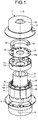
- FIG. 1 is a development view of a DC brushless motor, which is an electric motor according to a first embodiment of the present invention.
- the DC brushless motor 1 which is an electric motor
- each element is housed inside a casing constituted by a frame 2 and a bracket 3.
- the frame 2 has a bottomed cylindrical shape and is made of metal.
- a stator 4 having a sleeve shape is press-fitted inside the frame 2.
- the stator 4 is configured by winding a coil 6 around an iron core 5 via an insulator 16.
- the stator 4 is provided with an output pin 14.
- a rotor 7 having an annular shape is disposed inside the stator 4.
- a shaft 8 stretching along a central axis C of the stator 4 is coupled to the rotor 7.
- One end side of the shaft 8 protrudes outside the frame 2.
- a second bearing 9 is provided closer to the side of the frame 2 than a coupling portion with the rotor 7, and a first bearing 10 is provided closer to the side of the bracket 3 than the coupling portion with the rotor 7.
- Each of the bearings 9 and 10 holds the shaft 8 rotatably about the central axis C.
- the second bearing 9 is held in a housing formed in the frame 2.
- the first bearing 10 is held in a housing formed in the bracket 3.
- FIG. 2 is a diagram schematically illustrating a cross-sectional configuration of a portion between the stator 4 and the bracket 3 in the first embodiment.
- a circuit board 15 is provided on an opposite side of the stator 4 with the board case 13 interposed.
- FIG. 3 is a diagram of the circuit board 15 in the first embodiment as viewed from the side of a mounting surface 15a.
- the electronic component 31 constitutes the function of a drive unit, a control unit, or a power supply unit.
- the drive unit is exemplified by a configuration using a three-phase bridge driver in which six discrete elements of a one-chip inverter integrated circuit (IC) or an insulated gate bipolar transistor (IGBT) are combined with a motor driver IC.
- the control unit is exemplified by a configuration using a microcomputer or a programmable logic controller (PLC).
- PLC programmable logic controller
- the output pin 14 of the stator 4 passes through a through-hole (not illustrated) formed in the board case 13 and protrudes toward the side of the mounting surface 15a of the circuit board 15 farther from the board case 13.
- the output pin 14 is electroconductively connected to the circuit board 15 by soldering or the like.
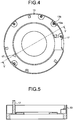
- FIG. 4 is a plan view of the board case 13 in the first embodiment.
- FIG. 5 is a cross-sectional view taken along line V-V illustrated in FIG. 4 .
- the board case 13 is provided with a projection 13a that positions the circuit board 15.
- a pilot hole 13b for a screw is formed in the board case 13.
- the circuit board 15 positioned by the projection 13a is fixed by screwing a screw into the pilot hole 13b, whereby the circuit board 15 is fixed and positioned to the board case 13.
- the board case 13 is provided with an extension portion 17 that extends toward the circuit board 15.
- the extension portions 17 pass through through-holes 30a and 30b formed in the circuit board 15.
- the first embodiment illustrates an example in which two extension portions 17 are provided, but three or more extension portions 17 may be provided.
- the extension portion 17 is formed with a length for protruding toward a side of a facing surface 3a farther from the circuit board 15.
- the facing surface 3a is a surface of the bracket 3 that faces the mounting surface 15a of the circuit board 15.
- the shape of the extension portion 17 is a triangular prism shape.
- the extension portion 17 is formed of an insulating material, for example, a resin.
- a heat transfer component 40 is provided between the facing surface 3a of the bracket 3 and the electronic component 31.
- the heat transfer component 40 transfers heat generated in the electronic component 31 to the bracket 3.
- the heat transfer component 40 is made of, for example, metal.
- FIG. 6 is a plan view of the heat transfer component 40 in the first embodiment.
- the heat transfer component 40 is formed with a first engagement portion 18 in which the extension portion 17 is inserted and engaged.
- the first engagement portion 18 is a groove stretching in a direction along the central axis C.
- the first engagement portion 18 is a trapezoidal groove as viewed in plan, and accommodates two apexes of the extension portion 17 having a triangular shape as viewed in plan, in the groove.
- a heat dissipation sheet 32 is disposed between the heat transfer component 40 and the electronic component 31.
- the heat dissipation sheet 32 is constituted of a substance having heat dissipation properties and elasticity.
- the heat dissipation sheet 32 is sandwiched between the heat transfer component 40 and the electronic component 31 and compressed, such that movement in a direction perpendicular to the central axis C is restricted.
- the heat dissipation sheet 32 has adhesiveness in some cases. Examples of the heat dissipation sheet 32 include a silicone gel having excellent thermal conductivity.
- the heat transfer component 40 can be fixed using the extension portion 17 formed in the board case 13 without using a screw, such that an assembly process such as fastening the screw can be reduced.
- the number of components can be reduced.
- the extension portion 17 that fixes the heat transfer component 40 is provided inside the casing, an increase in the size of the DC brushless motor 1 can be suppressed.
- the extension portion 17 that passes through the circuit board 15 is formed of an insulating material, it is not necessary to provide a region for maintaining an insulating distance with the extension portion 17 in the circuit board 15. Therefore, a decrease in the implementation area of the circuit board 15 can be suppressed as compared with a case where the circuit board 15 is fixed using a metal screw.
- FIG. 7 is a diagram illustrating a first modification of the heat transfer component 40 in the first embodiment.
- the shape of the first engagement portion 18 as viewed in plan may be a rectangular shape.
- the shape of the extension portion 17 engaged with the first engagement portion 18 is a quadrangular prism shape.
- FIG. 8 is a diagram illustrating a second modification of the heat transfer component 40 in the first embodiment.
- the first engagement portion 18 as viewed in plan may be a hole having a circular shape.
- the shape of the extension portion 17 engaged with the first engagement portion 18 is a columnar shape. Note that the shape of the hole is not limited to a circular shape.
- FIG. 9 is a diagram illustrating a third modification of the heat transfer component 40 in the first embodiment.
- the shape of the heat transfer component 40 as viewed in plan may be a rectangular shape as illustrated in FIG. 9 instead of an arc shape.
- the DC brushless motor 1 when an external power supply is supplied to the power supply unit, the DC brushless motor 1 generates a driving torque for rotating the rotor 7 whose load is connected to the shaft 8, by causing the drive unit to energize and drive the coil 6 in response to a control command from the control unit.
- FIG. 10 is a development view of a DC brushless motor 50 according to a second embodiment of the present invention.
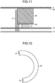
- FIG. 11 is a diagram schematically illustrating a cross-sectional configuration of a portion between the stator 4 and the bracket 3 in the second embodiment. Note that the same constituent members as those in the first embodiment described above are denoted by the same reference numerals and detailed description thereof will be omitted.
- an insulation component 26 is sandwiched between the heat transfer component 40 and the electronic component 31.
- the insulation component 26 is formed of an insulating material and insulates the heat transfer component 40 and the electronic component 31 from each other.
- the insulation component 26 does not have elasticity and adhesiveness as compared with the heat dissipation sheet 32 illustrated in the first embodiment described above, and is sometimes not sufficiently fixed only by being sandwiched between the heat transfer component 40 and the electronic component 31. Meanwhile, the insulation component 26 is more excellent in electrical insulation properties than the heat dissipation sheet 32 illustrated in the above first embodiment.
- Examples of the insulation component 26 include a polyester film or a silicone rubber having excellent thermal conductivity.
- FIG. 12 is a plan view of the insulation component 26 in the second embodiment.
- the insulation component 26 is formed with a second engagement portion 27 that engages with the extension portion 17.
- the insulation component 26 can be fixed to the board case 13 by engaging the second engagement portion 27 with the extension portion 17.
- the insulation component 26 can be fixed using the extension portion 17 formed in the board case 13 without using a screw, such that an assembly process such as fastening the screw can be reduced.
- the number of components can be reduced.
- the extension portion 17 that fixes the insulation component 26 is provided inside the casing, an increase in the size of the DC brushless motor 50 can be suppressed.
- the shape of the insulation component 26 as viewed in plan and the shape of the second engagement portion 27 can be modified as appropriate.
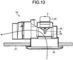
- FIG. 13 is a cross-sectional view of a ventilation fan 19 mounted with the DC brushless motor 1 according to the first embodiment or the DC brushless motor 50 according to the second embodiment.
- the DC brushless motor 1 or the DC brushless motor 50 is mounted on a casing 33 of the ventilation fan 19, and a blower fan 20 is attached to the shaft 8. After the casing 33 is embedded and installed in a ceiling plate 21, a grill 22 is attached from below.
- the bracket 3 of the DC brushless motors 1 and 50 protrudes outside the casing 33 of the ventilation fan 19, and thus an increase in the size of the DC brushless motors 1 and 50 leads to an increase in the size of the ventilation fan 19.
- the ventilation fan 19 can be downsized. Accordingly, it becomes easier to install the ventilation fan 19 in a ceiling cavity or the like where the space is limited.
- the configuration illustrated in the above embodiments indicates examples of the content of the present invention and can be combined with another known technology. A part of the configuration can also be omitted and modified without departing from the gist of the present invention.
Landscapes
- Engineering & Computer Science (AREA)
- Microelectronics & Electronic Packaging (AREA)
- Power Engineering (AREA)
- Physics & Mathematics (AREA)
- Thermal Sciences (AREA)
- Cooling Or The Like Of Electrical Apparatus (AREA)
- Motor Or Generator Frames (AREA)
- Motor Or Generator Cooling System (AREA)
Applications Claiming Priority (1)
| Application Number | Priority Date | Filing Date | Title |
|---|---|---|---|
| PCT/JP2017/025960 WO2019016865A1 (ja) | 2017-07-18 | 2017-07-18 | 電動機および換気扇 |
Publications (3)
| Publication Number | Publication Date |
|---|---|
| EP3657647A1 true EP3657647A1 (de) | 2020-05-27 |
| EP3657647A4 EP3657647A4 (de) | 2020-07-08 |
| EP3657647B1 EP3657647B1 (de) | 2021-06-16 |
Family
ID=65016657
Family Applications (1)
| Application Number | Title | Priority Date | Filing Date |
|---|---|---|---|
| EP17917933.8A Active EP3657647B1 (de) | 2017-07-18 | 2017-07-18 | Elektromotor und lüftungsgebläse |
Country Status (5)
| Country | Link |
|---|---|
| US (1) | US11451115B2 (de) |
| EP (1) | EP3657647B1 (de) |
| JP (1) | JP6735923B2 (de) |
| CN (1) | CN110915111B (de) |
| WO (1) | WO2019016865A1 (de) |
Cited By (1)
| Publication number | Priority date | Publication date | Assignee | Title |
|---|---|---|---|---|
| US12126226B2 (en) | 2021-11-11 | 2024-10-22 | Snap-On Incorporated | Motor controller for a tool |
Families Citing this family (2)
| Publication number | Priority date | Publication date | Assignee | Title |
|---|---|---|---|---|
| TWI768689B (zh) * | 2021-01-29 | 2022-06-21 | 朝程工業股份有限公司 | 馬達結構 |
| EP4376276A1 (de) * | 2022-11-25 | 2024-05-29 | Bühler Motor GmbH | Elektromotor für ein fahrzeugrad |
Family Cites Families (19)
| Publication number | Priority date | Publication date | Assignee | Title |
|---|---|---|---|---|
| JPS57148554A (en) * | 1981-03-06 | 1982-09-13 | Hitachi Ltd | Cooler for blower driving motor |
| US4643653A (en) * | 1984-10-15 | 1987-02-17 | Jidosha Kiki Co., Ltd. | Electromagnetic pump |
| FR2603667B1 (fr) | 1986-09-10 | 1990-09-28 | Etri Sa | Ventilateur centrifuge entraine par un moteur a courant continu et a commutation electronique |
| WO1997033359A1 (en) * | 1996-03-07 | 1997-09-12 | Seiko Epson Corporation | Motor and process for producing the same |
| JP2001086724A (ja) * | 1999-09-14 | 2001-03-30 | Matsushita Electric Ind Co Ltd | 磁気センサー付きステッピングモータ |
| US20060061997A1 (en) * | 2004-09-20 | 2006-03-23 | Cao Group, Inc. | Serviceable, exchangeable LED assembly |
| PL1696070T3 (pl) * | 2005-02-25 | 2011-05-31 | Askoll Holding Srl | Pralka lub podobny sprzęt gospodarstwa domowego uruchamiany przez synchroniczny silnik elektryczny z urządzeniem wykrywającym warunki niewyważenia |
| CN101260891A (zh) * | 2007-03-09 | 2008-09-10 | 富准精密工业(深圳)有限公司 | 散热风扇及其制造方法 |
| JP5248814B2 (ja) * | 2007-07-18 | 2013-07-31 | 日立オートモティブシステムズ株式会社 | モータ駆動装置およびその検査方法 |
| FR2967845B1 (fr) * | 2010-11-23 | 2013-08-02 | Valeo Equip Electr Moteur | Architecture de modules electroniques de puissance interconnectes pour une machine electrique tournante et machine electrique tournante comprenant une telle architecture |
| JP5839959B2 (ja) * | 2011-11-22 | 2016-01-06 | アスモ株式会社 | 制御モータ |
| JP6017823B2 (ja) * | 2012-04-23 | 2016-11-02 | 日本電産サンキョー株式会社 | ドライバ一体型モータ |
| JP2015144532A (ja) | 2014-01-31 | 2015-08-06 | 株式会社富士通ゼネラル | 電動機 |
| DE102014004262A1 (de) * | 2014-03-20 | 2015-09-24 | Ziehl-Abegg Se | Elektromotor, insbesondere Außenläufermotor, sowie Zwischenisolierteil für einen Elektromotor |
| JP6569306B2 (ja) * | 2014-09-30 | 2019-09-04 | 日本電産株式会社 | モータ |
| DE112014007081T5 (de) * | 2014-10-21 | 2017-07-06 | Mitsubishi Electric Corporation | Elektromotor und Belüftungsgebläse |
| JP6540986B2 (ja) * | 2015-01-26 | 2019-07-10 | 株式会社デンソー | 回転電機 |
| US10793182B2 (en) * | 2015-02-18 | 2020-10-06 | Mitsubishi Electric Corporation | Integrated electric power steering apparatus |
| JP6593625B2 (ja) * | 2015-05-25 | 2019-10-23 | 株式会社ジェイテクト | 回転角検出装置 |
-
2017
- 2017-07-18 EP EP17917933.8A patent/EP3657647B1/de active Active
- 2017-07-18 WO PCT/JP2017/025960 patent/WO2019016865A1/ja not_active Ceased
- 2017-07-18 JP JP2019530267A patent/JP6735923B2/ja active Active
- 2017-07-18 US US16/627,526 patent/US11451115B2/en active Active
- 2017-07-18 CN CN201780091636.3A patent/CN110915111B/zh active Active
Cited By (1)
| Publication number | Priority date | Publication date | Assignee | Title |
|---|---|---|---|---|
| US12126226B2 (en) | 2021-11-11 | 2024-10-22 | Snap-On Incorporated | Motor controller for a tool |
Also Published As
| Publication number | Publication date |
|---|---|
| EP3657647A4 (de) | 2020-07-08 |
| WO2019016865A1 (ja) | 2019-01-24 |
| JPWO2019016865A1 (ja) | 2019-11-07 |
| EP3657647B1 (de) | 2021-06-16 |
| CN110915111A (zh) | 2020-03-24 |
| US11451115B2 (en) | 2022-09-20 |
| US20200136469A1 (en) | 2020-04-30 |
| CN110915111B (zh) | 2021-11-30 |
| JP6735923B2 (ja) | 2020-08-05 |
Similar Documents
| Publication | Publication Date | Title |
|---|---|---|
| CN106067711B (zh) | 车辆用马达驱动控制装置 | |
| US11451115B2 (en) | Electric motor with a heat transfer component, circuit board and a ventilation fan | |
| JP6505311B2 (ja) | 電動機および換気扇 | |
| EP3806289A1 (de) | Elektrische rotationsmaschine | |
| JP6647152B2 (ja) | Dcブラシレスモータおよび換気送風機 | |
| JP6648569B2 (ja) | 車両用モータ駆動制御装置 | |
| CN113169627A (zh) | 电动驱动装置 | |
| JP2015144532A (ja) | 電動機 | |
| CN107306513B (zh) | 电动机和换气扇 | |
| JP7395924B2 (ja) | モータ装置 | |
| JP5591184B2 (ja) | 電動機 | |
| JP2024163656A (ja) | Dcブラシレスモータおよび換気扇 | |
| JP6338719B1 (ja) | 電動駆動装置 | |
| JP2015115593A (ja) | 電動機、空気調和機、および電動機の製造方法 | |
| EP3657648A1 (de) | Elektromotor und lüftungsgebläse | |
| JP2004159464A (ja) | モータ | |
| JP2002161894A (ja) | 電動送風装置 | |
| US20210119513A1 (en) | Electric motor and ventilating fan | |
| JP2010233348A (ja) | 電動機 | |
| JP2017191656A (ja) | 電子装置 | |
| JP6439834B2 (ja) | 制御装置 | |
| JP2014053373A (ja) | 回路基板 | |
| JP2014049610A (ja) | 回路基板 | |
| JP2013223394A (ja) | 同期回転機の固定子および空調用ブラシレスdcファンモータ | |
| JP2016157986A (ja) | 回路基板 |
Legal Events
| Date | Code | Title | Description |
|---|---|---|---|
| STAA | Information on the status of an ep patent application or granted ep patent |
Free format text: STATUS: THE INTERNATIONAL PUBLICATION HAS BEEN MADE |
|
| PUAI | Public reference made under article 153(3) epc to a published international application that has entered the european phase |
Free format text: ORIGINAL CODE: 0009012 |
|
| STAA | Information on the status of an ep patent application or granted ep patent |
Free format text: STATUS: REQUEST FOR EXAMINATION WAS MADE |
|
| 17P | Request for examination filed |
Effective date: 20191211 |
|
| AK | Designated contracting states |
Kind code of ref document: A1 Designated state(s): AL AT BE BG CH CY CZ DE DK EE ES FI FR GB GR HR HU IE IS IT LI LT LU LV MC MK MT NL NO PL PT RO RS SE SI SK SM TR |
|
| AX | Request for extension of the european patent |
Extension state: BA ME |
|
| A4 | Supplementary search report drawn up and despatched |
Effective date: 20200608 |
|
| RIC1 | Information provided on ipc code assigned before grant |
Ipc: H02K 9/22 20060101ALI20200602BHEP Ipc: H05K 7/20 20060101ALI20200602BHEP Ipc: H02K 11/33 20160101AFI20200602BHEP |
|
| DAV | Request for validation of the european patent (deleted) | ||
| DAX | Request for extension of the european patent (deleted) | ||
| GRAP | Despatch of communication of intention to grant a patent |
Free format text: ORIGINAL CODE: EPIDOSNIGR1 |
|
| STAA | Information on the status of an ep patent application or granted ep patent |
Free format text: STATUS: GRANT OF PATENT IS INTENDED |
|
| INTG | Intention to grant announced |
Effective date: 20210315 |
|
| GRAS | Grant fee paid |
Free format text: ORIGINAL CODE: EPIDOSNIGR3 |
|
| GRAA | (expected) grant |
Free format text: ORIGINAL CODE: 0009210 |
|
| STAA | Information on the status of an ep patent application or granted ep patent |
Free format text: STATUS: THE PATENT HAS BEEN GRANTED |
|
| AK | Designated contracting states |
Kind code of ref document: B1 Designated state(s): AL AT BE BG CH CY CZ DE DK EE ES FI FR GB GR HR HU IE IS IT LI LT LU LV MC MK MT NL NO PL PT RO RS SE SI SK SM TR |
|
| REG | Reference to a national code |
Ref country code: GB Ref legal event code: FG4D |
|
| REG | Reference to a national code |
Ref country code: CH Ref legal event code: EP |
|
| REG | Reference to a national code |
Ref country code: DE Ref legal event code: R096 Ref document number: 602017040613 Country of ref document: DE |
|
| REG | Reference to a national code |
Ref country code: AT Ref legal event code: REF Ref document number: 1403160 Country of ref document: AT Kind code of ref document: T Effective date: 20210715 |
|
| REG | Reference to a national code |
Ref country code: IE Ref legal event code: FG4D |
|
| REG | Reference to a national code |
Ref country code: LT Ref legal event code: MG9D |
|
| PG25 | Lapsed in a contracting state [announced via postgrant information from national office to epo] |
Ref country code: LT Free format text: LAPSE BECAUSE OF FAILURE TO SUBMIT A TRANSLATION OF THE DESCRIPTION OR TO PAY THE FEE WITHIN THE PRESCRIBED TIME-LIMIT Effective date: 20210616 Ref country code: FI Free format text: LAPSE BECAUSE OF FAILURE TO SUBMIT A TRANSLATION OF THE DESCRIPTION OR TO PAY THE FEE WITHIN THE PRESCRIBED TIME-LIMIT Effective date: 20210616 Ref country code: BG Free format text: LAPSE BECAUSE OF FAILURE TO SUBMIT A TRANSLATION OF THE DESCRIPTION OR TO PAY THE FEE WITHIN THE PRESCRIBED TIME-LIMIT Effective date: 20210916 Ref country code: HR Free format text: LAPSE BECAUSE OF FAILURE TO SUBMIT A TRANSLATION OF THE DESCRIPTION OR TO PAY THE FEE WITHIN THE PRESCRIBED TIME-LIMIT Effective date: 20210616 |
|
| REG | Reference to a national code |
Ref country code: AT Ref legal event code: MK05 Ref document number: 1403160 Country of ref document: AT Kind code of ref document: T Effective date: 20210616 |
|
| REG | Reference to a national code |
Ref country code: NL Ref legal event code: MP Effective date: 20210616 |
|
| PG25 | Lapsed in a contracting state [announced via postgrant information from national office to epo] |
Ref country code: LV Free format text: LAPSE BECAUSE OF FAILURE TO SUBMIT A TRANSLATION OF THE DESCRIPTION OR TO PAY THE FEE WITHIN THE PRESCRIBED TIME-LIMIT Effective date: 20210616 Ref country code: NO Free format text: LAPSE BECAUSE OF FAILURE TO SUBMIT A TRANSLATION OF THE DESCRIPTION OR TO PAY THE FEE WITHIN THE PRESCRIBED TIME-LIMIT Effective date: 20210916 Ref country code: RS Free format text: LAPSE BECAUSE OF FAILURE TO SUBMIT A TRANSLATION OF THE DESCRIPTION OR TO PAY THE FEE WITHIN THE PRESCRIBED TIME-LIMIT Effective date: 20210616 Ref country code: SE Free format text: LAPSE BECAUSE OF FAILURE TO SUBMIT A TRANSLATION OF THE DESCRIPTION OR TO PAY THE FEE WITHIN THE PRESCRIBED TIME-LIMIT Effective date: 20210616 Ref country code: GR Free format text: LAPSE BECAUSE OF FAILURE TO SUBMIT A TRANSLATION OF THE DESCRIPTION OR TO PAY THE FEE WITHIN THE PRESCRIBED TIME-LIMIT Effective date: 20210917 |
|
| PG25 | Lapsed in a contracting state [announced via postgrant information from national office to epo] |
Ref country code: SK Free format text: LAPSE BECAUSE OF FAILURE TO SUBMIT A TRANSLATION OF THE DESCRIPTION OR TO PAY THE FEE WITHIN THE PRESCRIBED TIME-LIMIT Effective date: 20210616 Ref country code: SM Free format text: LAPSE BECAUSE OF FAILURE TO SUBMIT A TRANSLATION OF THE DESCRIPTION OR TO PAY THE FEE WITHIN THE PRESCRIBED TIME-LIMIT Effective date: 20210616 Ref country code: EE Free format text: LAPSE BECAUSE OF FAILURE TO SUBMIT A TRANSLATION OF THE DESCRIPTION OR TO PAY THE FEE WITHIN THE PRESCRIBED TIME-LIMIT Effective date: 20210616 Ref country code: ES Free format text: LAPSE BECAUSE OF FAILURE TO SUBMIT A TRANSLATION OF THE DESCRIPTION OR TO PAY THE FEE WITHIN THE PRESCRIBED TIME-LIMIT Effective date: 20210616 Ref country code: AT Free format text: LAPSE BECAUSE OF FAILURE TO SUBMIT A TRANSLATION OF THE DESCRIPTION OR TO PAY THE FEE WITHIN THE PRESCRIBED TIME-LIMIT Effective date: 20210616 Ref country code: CZ Free format text: LAPSE BECAUSE OF FAILURE TO SUBMIT A TRANSLATION OF THE DESCRIPTION OR TO PAY THE FEE WITHIN THE PRESCRIBED TIME-LIMIT Effective date: 20210616 Ref country code: NL Free format text: LAPSE BECAUSE OF FAILURE TO SUBMIT A TRANSLATION OF THE DESCRIPTION OR TO PAY THE FEE WITHIN THE PRESCRIBED TIME-LIMIT Effective date: 20210616 Ref country code: RO Free format text: LAPSE BECAUSE OF FAILURE TO SUBMIT A TRANSLATION OF THE DESCRIPTION OR TO PAY THE FEE WITHIN THE PRESCRIBED TIME-LIMIT Effective date: 20210616 Ref country code: PT Free format text: LAPSE BECAUSE OF FAILURE TO SUBMIT A TRANSLATION OF THE DESCRIPTION OR TO PAY THE FEE WITHIN THE PRESCRIBED TIME-LIMIT Effective date: 20211018 |
|
| REG | Reference to a national code |
Ref country code: DE Ref legal event code: R119 Ref document number: 602017040613 Country of ref document: DE |
|
| PG25 | Lapsed in a contracting state [announced via postgrant information from national office to epo] |
Ref country code: PL Free format text: LAPSE BECAUSE OF FAILURE TO SUBMIT A TRANSLATION OF THE DESCRIPTION OR TO PAY THE FEE WITHIN THE PRESCRIBED TIME-LIMIT Effective date: 20210616 |
|
| REG | Reference to a national code |
Ref country code: CH Ref legal event code: PL |
|
| PG25 | Lapsed in a contracting state [announced via postgrant information from national office to epo] |
Ref country code: MC Free format text: LAPSE BECAUSE OF FAILURE TO SUBMIT A TRANSLATION OF THE DESCRIPTION OR TO PAY THE FEE WITHIN THE PRESCRIBED TIME-LIMIT Effective date: 20210616 |
|
| REG | Reference to a national code |
Ref country code: BE Ref legal event code: MM Effective date: 20210731 |
|
| PLBE | No opposition filed within time limit |
Free format text: ORIGINAL CODE: 0009261 |
|
| STAA | Information on the status of an ep patent application or granted ep patent |
Free format text: STATUS: NO OPPOSITION FILED WITHIN TIME LIMIT |
|
| PG25 | Lapsed in a contracting state [announced via postgrant information from national office to epo] |
Ref country code: LI Free format text: LAPSE BECAUSE OF NON-PAYMENT OF DUE FEES Effective date: 20210731 Ref country code: DK Free format text: LAPSE BECAUSE OF FAILURE TO SUBMIT A TRANSLATION OF THE DESCRIPTION OR TO PAY THE FEE WITHIN THE PRESCRIBED TIME-LIMIT Effective date: 20210616 Ref country code: DE Free format text: LAPSE BECAUSE OF NON-PAYMENT OF DUE FEES Effective date: 20220201 Ref country code: CH Free format text: LAPSE BECAUSE OF NON-PAYMENT OF DUE FEES Effective date: 20210731 |
|
| 26N | No opposition filed |
Effective date: 20220317 |
|
| PG25 | Lapsed in a contracting state [announced via postgrant information from national office to epo] |
Ref country code: LU Free format text: LAPSE BECAUSE OF NON-PAYMENT OF DUE FEES Effective date: 20210718 Ref country code: AL Free format text: LAPSE BECAUSE OF FAILURE TO SUBMIT A TRANSLATION OF THE DESCRIPTION OR TO PAY THE FEE WITHIN THE PRESCRIBED TIME-LIMIT Effective date: 20210616 |
|
| PG25 | Lapsed in a contracting state [announced via postgrant information from national office to epo] |
Ref country code: IT Free format text: LAPSE BECAUSE OF FAILURE TO SUBMIT A TRANSLATION OF THE DESCRIPTION OR TO PAY THE FEE WITHIN THE PRESCRIBED TIME-LIMIT Effective date: 20210616 Ref country code: IE Free format text: LAPSE BECAUSE OF NON-PAYMENT OF DUE FEES Effective date: 20210718 Ref country code: BE Free format text: LAPSE BECAUSE OF NON-PAYMENT OF DUE FEES Effective date: 20210731 |
|
| P01 | Opt-out of the competence of the unified patent court (upc) registered |
Effective date: 20230512 |
|
| PG25 | Lapsed in a contracting state [announced via postgrant information from national office to epo] |
Ref country code: CY Free format text: LAPSE BECAUSE OF FAILURE TO SUBMIT A TRANSLATION OF THE DESCRIPTION OR TO PAY THE FEE WITHIN THE PRESCRIBED TIME-LIMIT Effective date: 20210616 |
|
| PG25 | Lapsed in a contracting state [announced via postgrant information from national office to epo] |
Ref country code: HU Free format text: LAPSE BECAUSE OF FAILURE TO SUBMIT A TRANSLATION OF THE DESCRIPTION OR TO PAY THE FEE WITHIN THE PRESCRIBED TIME-LIMIT; INVALID AB INITIO Effective date: 20170718 |
|
| PG25 | Lapsed in a contracting state [announced via postgrant information from national office to epo] |
Ref country code: MK Free format text: LAPSE BECAUSE OF FAILURE TO SUBMIT A TRANSLATION OF THE DESCRIPTION OR TO PAY THE FEE WITHIN THE PRESCRIBED TIME-LIMIT Effective date: 20210616 |
|
| REG | Reference to a national code |
Ref country code: GB Ref legal event code: 746 Effective date: 20240605 |
|
| PG25 | Lapsed in a contracting state [announced via postgrant information from national office to epo] |
Ref country code: TR Free format text: LAPSE BECAUSE OF FAILURE TO SUBMIT A TRANSLATION OF THE DESCRIPTION OR TO PAY THE FEE WITHIN THE PRESCRIBED TIME-LIMIT Effective date: 20210616 |
|
| PG25 | Lapsed in a contracting state [announced via postgrant information from national office to epo] |
Ref country code: MT Free format text: LAPSE BECAUSE OF FAILURE TO SUBMIT A TRANSLATION OF THE DESCRIPTION OR TO PAY THE FEE WITHIN THE PRESCRIBED TIME-LIMIT Effective date: 20210616 |
|
| PGFP | Annual fee paid to national office [announced via postgrant information from national office to epo] |
Ref country code: GB Payment date: 20250529 Year of fee payment: 9 |
|
| PGFP | Annual fee paid to national office [announced via postgrant information from national office to epo] |
Ref country code: FR Payment date: 20250610 Year of fee payment: 9 |