EP3657722A1 - Verfahren und vorrichtung für die zuordnung von referenzsignalsequenzen in der drahtlosen kommunikation - Google Patents
Verfahren und vorrichtung für die zuordnung von referenzsignalsequenzen in der drahtlosen kommunikation Download PDFInfo
- Publication number
- EP3657722A1 EP3657722A1 EP19203303.3A EP19203303A EP3657722A1 EP 3657722 A1 EP3657722 A1 EP 3657722A1 EP 19203303 A EP19203303 A EP 19203303A EP 3657722 A1 EP3657722 A1 EP 3657722A1
- Authority
- EP
- European Patent Office
- Prior art keywords
- antenna port
- port set
- mapping
- sequence
- index
- Prior art date
- Legal status (The legal status is an assumption and is not a legal conclusion. Google has not performed a legal analysis and makes no representation as to the accuracy of the status listed.)
- Granted
Links
Images







Classifications
-
- H—ELECTRICITY
- H04—ELECTRIC COMMUNICATION TECHNIQUE
- H04L—TRANSMISSION OF DIGITAL INFORMATION, e.g. TELEGRAPHIC COMMUNICATION
- H04L5/00—Arrangements affording multiple use of the transmission path
- H04L5/003—Arrangements for allocating sub-channels of the transmission path
- H04L5/0048—Allocation of pilot signals, i.e. of signals known to the receiver
- H04L5/0051—Allocation of pilot signals, i.e. of signals known to the receiver of dedicated pilots, i.e. pilots destined for a single user or terminal
-
- H—ELECTRICITY
- H04—ELECTRIC COMMUNICATION TECHNIQUE
- H04B—TRANSMISSION
- H04B7/00—Radio transmission systems, i.e. using radiation field
- H04B7/02—Diversity systems; Multi-antenna system, i.e. transmission or reception using multiple antennas
- H04B7/04—Diversity systems; Multi-antenna system, i.e. transmission or reception using multiple antennas using two or more spaced independent antennas
- H04B7/0413—MIMO systems
-
- H—ELECTRICITY
- H04—ELECTRIC COMMUNICATION TECHNIQUE
- H04L—TRANSMISSION OF DIGITAL INFORMATION, e.g. TELEGRAPHIC COMMUNICATION
- H04L5/00—Arrangements affording multiple use of the transmission path
- H04L5/0001—Arrangements for dividing the transmission path
- H04L5/0014—Three-dimensional division
- H04L5/0023—Time-frequency-space
Definitions
- the following description relates generally to wireless communications, and more particularly to mapping resource elements for transmission of a reference signal over a channel.
- Wireless communication systems are widely deployed to provide various types of communication content such as voice, data, and so on. These systems may be multiple-access systems capable of supporting communication with multiple users by sharing the available system resources (e.g., bandwidth and transmit power). Examples of such multiple-access systems include code division multiple access (CDMA) systems, time division multiple access (TDMA) systems, frequency division multiple access (FDMA) systems, 3GPP Long Term Evolution (LTE) systems, and orthogonal frequency division multiple access (OFDMA) systems.
- CDMA code division multiple access
- TDMA time division multiple access
- FDMA frequency division multiple access
- LTE 3GPP Long Term Evolution
- OFDMA orthogonal frequency division multiple access
- a wireless multiple-access communication system can simultaneously support communication for multiple wireless terminals.
- Each terminal communicates with one or more base stations via transmissions on the forward and reverse links.
- the forward link (or downlink) refers to the communication link from the base stations to the terminals
- the reverse link (or uplink) refers to the communication link from the terminals to the base stations.
- This communication link may be established via a single-in-single-out, multiple-in-signal-out or a multiple-in-multiple-out (MIMO) system.
- MIMO multiple-in-multiple-out
- a MIMO system employs multiple ( N T ) transmit antennas and multiple ( N R ) receive antennas for data transmission.
- a MIMO channel formed by the N T transmit and N R receive antennas may be decomposed into N S independent channels, which are also referred to as spatial channels, where N S ⁇ min ⁇ N T , N R ⁇ .
- Each of the N S independent channels corresponds to a dimension.
- the MIMO system can provide improved performance (e.g., higher throughput and/or greater reliability) if the additional dimensionalities created by the multiple transmit and receive antennas are utilized.
- Wireless systems often use reference signals in the uplink (UL) or in the downlink (DL) direction for channel characterization and performance improvement.
- LTE Long Term Evolution
- Rel-8 certain algorithms are defined for selecting time/frequency locations used for transmissions of the reference signals in UL or DL direction.
- these conventional algorithms are limited to a single layer transmission of certain reference signals, such as the user equipment reference signal (UE-RS).
- UE-RS user equipment reference signal
- MU-MIMO multi-user multiple-input, multiple-output
- the disclosed designs provide methods and apparatuses for mapping transmission resources to UE-RS in a MIMO system.
- a wireless communication method implemented in a multi-input multi-output MIMO system comprises forming one or more antenna port sets, wherein an antenna port set comprises two or more antenna ports and allocating transmission resources to a user equipment reference signal UE-RS, the allocating being based at least in part on an antenna port set index.
- a wireless communication apparatus for use in a multi-input multi-output MIMO system.
- the apparatus comprises means for forming one or more antenna port sets, wherein an antenna port set comprises two or more antenna ports and means for allocating transmission resources to a user equipment reference signal UE-RS, the allocating being based at least in part on an antenna port set index.
- a computer program product comprising a computer-readable storage medium.
- the computer-readable storage medium includes instructions for causing at least one computer to form one or more antenna port sets, wherein an antenna port set comprises two or more antenna ports and instructions for causing the at least one computer to allocate transmission resources to a user equipment reference signal UE-RS, the allocation being based at least in part on an antenna port set index.
- a wireless communication apparatus comprising a processor.
- the processor is configured for forming one or more antenna port sets, wherein an antenna port set comprises two or more antenna ports and allocating transmission resources to a user equipment reference signal UE-RS, the allocating being based at least in part on an antenna port set index.
- a wireless communication method implemented in a multi-input multi-output MIMO system comprises receiving an assignment of an antenna port set index wherein an antenna port set comprises two or more antenna ports and receiving transmission of a user equipment reference signal UE-RS, the transmission being based at least in part on the antenna port set index.
- a wireless communication apparatus for use in a multi-input multi-output MIMO system.
- the apparatus comprises means for receiving an assignment of an antenna port set index wherein an antenna port set comprises two or more antenna ports and means for receiving transmission of a user equipment reference signal UE-RS, the transmission being based at least in part on the antenna port set index.
- UE-RS user equipment reference signal
- a computer program product comprising a computer-readable storage medium.
- the computer-readable storage medium includes instructions for causing at least one computer to receive an assignment of an antenna port set index wherein an antenna port set comprises a logical group of two or more antenna ports and receive transmission of a user equipment reference signal UE-RS, the transmission being based at least in part on the antenna port set index.
- a wireless communication apparatus comprising a processor configured for receiving an assignment of an antenna port set index wherein an antenna port set comprises two or more antenna ports; and receiving transmission of a user equipment reference signal UE-RS, the transmission being based at least in part on the antenna port set index.
- CDMA Code Division Multiple Access
- TDMA Time Division Multiple Access
- FDMA Frequency Division Multiple Access
- OFDMA Orthogonal FDMA
- SC-FDMA Single-Carrier FDMA
- a CDMA network may implement a radio technology such as Universal Terrestrial Radio Access (UTRA), cdma2000, etc.
- UTRA includes Wideband-CDMA (W-CDMA) and Low Chip Rate (LCR).
- CDMA2000 covers IS-2000, IS-95 and IS-856 standards.
- a TDMA network may implement a radio technology such as Global System for Mobile Communications (GSM).
- GSM Global System for Mobile Communications
- An OFDMA network may implement a radio technology such as Evolved UTRA (E-UTRA), IEEE 802.11, IEEE 802.16, IEEE 802.20, Flash-OFDM®, etc.
- E-UTRA, E-UTRA, and GSM are part of Universal Mobile Telecommunication System (UMTS).
- LTE Long Term Evolution
- UTRA, E-UTRA, GSM, UMTS and LTE are described in documents from an organization named "3rd Generation Partnership Project" (3GPP).
- CDMA2000 is described in documents from an organization named "3rd Generation Partnership Project 2" (3GPP2).
- SC-FDMA Single carrier frequency division multiple access
- SC-FDMA Single carrier frequency division multiple access
- SC-FDMA signal has lower peak-to-average power ratio (PAPR) because of its inherent single carrier structure.
- PAPR peak-to-average power ratio
- SC-FDMA has drawn great attention, especially in the uplink communications where lower PAPR greatly benefits the mobile terminal in terms of transmit power efficiency. It is currently a working assumption for uplink multiple access scheme in 3GPP Long Term Evolution (LTE), or Evolved UTRA.
- LTE Long Term Evolution
- An access point 110 includes multiple antenna groups, one including 104 and 106, another including 108 and 100, and an additional including 112 and 114. In FIG. 1 , only two antennas are shown for each antenna group, however, more or fewer antennas may be utilized for each antenna group.
- Access terminal 120 is in communication with antennas 112 and 114, where antennas 112 and 114 transmit information to access terminal 120 over forward link 116 and receive information from access terminal 120 over reverse link 118.
- Access terminal 122 is in communication with antennas 106 and 108, where antennas 106 and 108 transmit information to access terminal 122 over forward link 126 and receive information from access terminal 122 over reverse link 124.
- communication links 118, 116, 124 and 126 may use different frequency for communication. For example, forward link 116 may use a different frequency then that used by reverse link 118.
- antenna groups each are designed to communicate to access terminals in a sector, of the areas covered by access point 110.
- the transmitting antennas of access point 110 utilize beamforming in order to improve the signal-to-noise ratio of forward links for the different access terminals 120 and 122. Also, an access point using beamforming to transmit to access terminals scattered randomly through its coverage causes less interference to access terminals in neighboring cells than an access point transmitting through a single antenna to all its access terminals.
- An access point 110 may be a fixed station used for communicating with the terminals and may also be referred to as an access point, a Node B (eNB), or some other terminology.
- An access terminal may also be called an access terminal, user equipment (UE), a wireless communication device, terminal, access terminal or some other terminology.
- UE user equipment
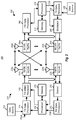
- FIG. 2 is a block diagram of an embodiment of a transmitter system 210 (also known as the access point or eNB) and a receiver system 250 (also known as access terminal or UE) in a MIMO system 200.
- a transmitter system 210 also known as the access point or eNB
- a receiver system 250 also known as access terminal or UE
- traffic data for a number of data streams is provided from a data source 212 to a transmit (TX) data processor 214.
- TX transmit
- each data stream is transmitted over a respective transmit antenna.
- TX data processor 214 formats, codes, and interleaves the traffic data for each data stream based on a particular coding scheme selected for that data stream to provide coded data.
- the coded data for each data stream may be multiplexed with pilot data using OFDM techniques.
- the pilot data is typically a known data pattern that is processed in a known manner and may be used at the receiver system to estimate the channel response.
- the multiplexed pilot and coded data for each data stream is then modulated (i.e., symbol mapped) based on a particular modulation scheme (e.g., BPSK, QSPK, M-PSK, or M-QAM) selected for that data stream to provide modulation symbols.
- a particular modulation scheme e.g., BPSK, QSPK, M-PSK, or M-QAM
- the data rate, coding, and modulation for each data stream may be determined by instructions performed by processor 230.
- TX MIMO processor 220 may further process the modulation symbols (e.g., for OFDM).
- TX MIMO processor 220 then provides N T modulation symbol streams to N T transmitters (TMTR) 222a through 222t.
- TMTR TX MIMO processor 220 applies beamforming weights to the symbols of the data streams and to the antenna from which the symbol is being transmitted.
- Each transmitter 222 receives and processes a respective symbol stream to provide one or more analog signals, and further conditions (e.g., amplifies, filters, and upconverts) the analog signals to provide a modulated signal suitable for transmission over the MIMO channel.
- N T modulated signals from transmitters 222a through 222t are then transmitted from N T antennas 224a through 224t, respectively.
- the transmitted modulated signals are received by N R antennas 252a through 252r and the received signal from each antenna 252 is provided to a respective receiver (RCVR) 254a through 254r.
- Each receiver 254 conditions (e.g., filters, amplifies, and downconverts) a respective received signal, digitizes the conditioned signal to provide samples, and further processes the samples to provide a corresponding "received" symbol stream.
- An RX data processor 260 then receives and processes the N R received symbol streams from N R receivers 254 based on a particular receiver processing technique to provide N T "detected" symbol streams.
- the RX data processor 260 then demodulates, deinterleaves, and decodes each detected symbol stream to recover the traffic data for the data stream.
- the processing by RX data processor 260 is complementary to that performed by TX MIMO processor 220 and TX data processor 214 at transmitter system 210.
- a processor 270 periodically determines which pre-coding matrix to use (discussed below). Processor 270 formulates a reverse link message comprising a matrix index portion and a rank value portion.
- the reverse link message may comprise various types of information regarding the communication link and/or the received data stream.
- the reverse link message is then processed by a TX data processor 238, which also receives traffic data for a number of data streams from a data source 236, modulated by a modulator 280, conditioned by transmitters 254a through 254r, and transmitted back to transmitter system 210.
- the modulated signals from receiver system 250 are received by antennas 224, conditioned by receivers 222, demodulated by a demodulator 240, and processed by a RX data processor 242 to extract the reserve link message transmitted by the receiver system 250.
- Processor 230 determines which pre-coding matrix to use for determining the beamforming weights then processes the extracted message.
- Logical Control Channels comprises Broadcast Control Channel (BCCH) which is DL channel for broadcasting system control information. Paging Control Channel (PCCH) which is DL channel that transfers paging information.
- Multicast Control Channel (MCCH) which is Point-to-multipoint DL channel used for transmitting Multimedia Broadcast and Multicast Service (MBMS) scheduling and control information for one or several MTCHs.
- BCCH Broadcast Control Channel
- PCCH Paging Control Channel
- MCCH Multicast Control Channel
- MCCH Point-to-multipoint DL channel used for transmitting Multimedia Broadcast and Multicast Service (MBMS) scheduling and control information for one or several MTCHs.
- MBMS Multimedia Broadcast and Multicast Service
- DCCH Dedicated Control Channel
- Logical Traffic Channels comprises a Dedicated Traffic Channel (DTCH) which is Point-to-point bi-directional channel, dedicated to one UE, for the transfer of user information. Also, a Multicast Traffic Channel (MTCH) for Point-to-multipoint DL channel for transmitting traffic data.
- DTCH Dedicated Traffic Channel
- MTCH Multicast Traffic Channel
- Transport Channels are classified into DL and UL.
- DL Transport Channels comprises a Broadcast Channel (BCH), Downlink Shared Data Channel (DL-SDCH) and a Paging Channel (PCH), the PCH for support of UE power saving (DRX cycle is indicated by the network to the UE), broadcasted over entire cell and mapped to PHY resources which can be used for other control/traffic channels.
- the UL Transport Channels comprises a Random Access Channel (RACH), a Request Channel (REQCH), a Uplink Shared Data Channel (UL-SDCH) and plurality of PHY channels.
- the PHY channels comprises a set of DL channels and UL channels.
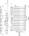
- FIG. 3 shows a DL transmission format in certain wireless systems. This representation is sometimes called a "resource grid," referring to transmission resources shown.
- the transmissions may be logically organized as successive transmissions of radio frames 302.
- a radio frame 302 may, for example, have a predetermined time duration.
- Each radio frame 302 may further be organized as a number of subframes 304, each subframe 304 comprising a number of slots 305 in which a number of orthogonal frequency domain multiplexing (OFDM) symbols are transmitted (depicted along horizontal axis 310).
- Each OFDM symbol may comprise a number of subcarriers (depicted along vertical axis 312), at least some of which can be assigned to different signals, independent of each other.
- a radio frame 302 represents 10 ms and comprises ten subframes 304, each occupying 1 ms.
- Each subframe 304 comprises two slots 305 (even-numbered and odd-numbered slot).
- CP normal cyclic prefix
- seven OFDM symbols may be transmitted in each slot 305 and, for extended CP transmissions (not shown), six OFDM symbols may be transmitted in each slot.
- one subcarrier of one OFDM symbol may represent the smallest unit of allocation of transmission resources, shown in FIG. 3 as a resource element 306 (RE).
- one RE 306 may correspond to a 15 KHz subcarrier assignment within a single OFDM symbol.
- subcarriers may be assigned in units of a certain number of sub-carriers (e.g., twelve), resulting in a physical resource block (e.g., 180 KHz), representing a unit of transmission resources assigned to a certain transmission.
- a certain number of sub-carriers e.g., twelve
- a physical resource block e.g. 180 KHz
- transmission resources (or REs 306) assigned to transmissions of a particular signal may be varied as a function of a radio frame index, a subframe index within a radio frame 302 (e.g., 0 to 9), a slot index within a subframe 304 (e.g., 0 or 1), an OFDM symbol index within a slot and a subcarrier index within the OFDM symbol. While such a large number of degrees of freedom are available to a scheduler to allocate REs 306 to the transmission of a particular signal, in practice, a certain amount of predictability and repetitiveness is introduced to simplify the allocation of REs 306 to signal transmissions. This simplification may help, for example, relieve a scheduler of the computational burden and also reduced the transmission overhead required to signal RE locations for transmission signals to intended receivers.
- transmission resource assignment for certain transmissions may be performed using certain predetermined patterns, known to both a transmitter and a receiver, to compute locations of REs 306 assigned to the transmissions, at both the transmitter and the receiver, without having to explicitly signal the locations.
- the reference signals may be scrambled by predetermined pseudo-random sequence, known to both a transmitter and a receiver.
- the pseudo-random sequences may be determined by initialization parameters or initialization sequences known to both a transmitter and a receiver.
- the initialization sequences may, for example, be initialized at the beginning of each symbol, to compute the pseudo-random sequence within the symbol.
- the pseudo-random assignment of modulation symbol values to be used in REs 306 may help reduce or eliminate interference or cross-correlation between different transmitters. Furthermore, pseudo-random assignment of modulation symbol values to be used in REs 306 may also improve channel estimation performance.
- the pseudo-random sequence c ( i ) is defined in Section 7.2 of the Rel-8 specification.
- the initialization shown in Eq. (3) is bandwidth agnostic.
- the CRS allocation uses the maximum possible DL bandwidth available in initialization of the sequence generator used for RE mapping.
- the initialization sequence shown in Eq. (2) and (3) is a function of the slot number and the OFDM symbol number, the sequence is initialized differently for different symbols and different slots.
- the initialization is cell-specific and is dependent on the CP type (normal or extended).
- v shift N ID cell mod 6.
- N RB max , DL represents the maximum DL bandwidth (in RBs).
- LTE-8 specifies that within one symbol, the mapping is contiguous using the same initialization and across symbols (in the same slot or different slots), the same set of samples are used but with different initializations.
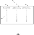
- the initialization of the sequence is similar to the initialization described with respect to FIG. 4 .
- Column 504 lists offsets m' from the initialized sequence.
- UE-specific reference signal (UE-RS) is specified to support single-layer beamforming.
- the pseudo-random sequence c ( i ) is defined in Section 7.2 of 3GPP TS 36.211.
- v shift N ID cell mod 3.
- Rel-8 further specifies that the mapping will be in the increasing order of the frequency-domain index n PRB of the PRBs assigned for the corresponding PDSCH transmission.
- the quantity N RB PDSCH denotes the bandwidth in resource blocks of the corresponding PDSCH transmission.
- Columns 614, 616, 618 and 620 correspond to offset values for symbol index numbers 3, 6, 2 and 5, respectively.
- the three RBs assigned to the PDSCH are not contiguous.
- the UE-RS mapping for symbol index 3 (column 614) runs from 0 (top of the column 614) to 8 (bottom of the column 614).
- the resource mapping is contiguous from the end of one symbol to the beginning of the next symbol (e.g., arrow 602 indicates mapping index is "9" at the top of column 616, which is contiguous to the last mapping index "8" for the previous symbol index 3.)
- n PRB, 1 is not necessarily equal to 0 (the first PRB of the system). Regardless of whether the 3 RBs are contiguous or not, the same mapping shown in FIG. 6 is applicable, which demonstrates that the UE-RS mapping is contiguous in the assigned PDSCH resources.
- two UE-RS antenna ports are available for transmission within a given RE.
- the two antenna ports may be code division multiplexed (CDM).
- CDM code division multiplexed
- Eq. (9) if the sequence is initialized depending on a UE specific ID, the sequences generated for the paired UEs 120 may no longer be the same. As a result, the desired orthogonality of transmissions may not be maintained.
- one UE 120 may not know the pseudo-random sequence used by the other paired UE 120, as the UE-IDs are not mutually known between the paired UEs 120. Such non-orthogonality and unknown information about the other random sequence may cause significant interference on UE-RS, thereby reducing performance of a wireless system.
- the random sequence is generated dependent on the assigned PDSCH bandwidth N RB PDSCH and mapped to the specific locations of the assigned PDSCH resources. It may be possible that UEs 120 paired in MU-MIMO transmissions may not be completely aligned (both in terms of the assigned bandwidth and the assigned location).
- a first PDSCH resource 702 is shown which is assigned to a first UE 120 and a second PDSCH 704 is assigned to a second UE 120 that is paired with the first UE 120. It is clear that the PDSCH bandwidths associated with the first and second PDSCHs 702, 704 are not equal and are not aligned. In such a case, the pseudo-random sequences used for resource allocation for the paired UEs 120 may not be orthogonal.
- c init may further be dependent on an antenna port index, a CP type, an RB ID, or a combination thereof.
- the cell-specific initialization may not be applicable.
- N ID ServingCell is an identification number of the serving cell for a UE 120
- n S is the slot number
- ⁇ ⁇ represents the floor operation.
- Certain designs provide for techniques to map the sequence to resource elements such that the allocation density is dependent on a transmission rank. Furthermore, certain designs, further described below, provide for techniques in which allocated locations of REs 306 for UE-RS transmissions are dependent on antenna port indices. For example, two or more antenna ports may share the same set of REs 306 and may be differentiated in a CDM manner. Therefore, in general, UE-RS antenna ports can be differentiated via a mixture of CDM (if occupying the same frequency resources) and FDM.
- the allocation pattern for UE-RS is dependent on CP type (normal or extended), a subframe type, e.g., regular subframes, special subframes in TDD (DwPTS), relaying backhaul subframes, etc.
- CP type normal or extended
- subframe type e.g., regular subframes, special subframes in TDD (DwPTS), relaying backhaul subframes, etc.
- the following the UE-RS sequence r ( m ) may be used.
- FIGs. 8 , 9 , 10 and 11 some examples of UE-RS resource allocation patterns according to techniques described in this disclosure are shown.
- FIG. 8 shows a resource grid 800 for a subframe with a normal CP.
- the horizontal axis 802 may represent time (symbol index) and the vertical axis may represent frequency.
- the resource elements (tiles) marked “C" may represent resources allocated to legacy references signals such as the common reference signal (CRS).
- Resource elements labeled U1 may be transmission resources allocation to a first antenna port set comprising two antenna ports.
- Resource elements labeled U2 may be transmission resources allocation to a second antenna port set comprising two antenna ports.
- the depicted example in FIG. 8 may correspond to a rank 3-4 system.
- the antenna ports forming an antenna port set may be, for example, 0/1 or 2/3. While each antenna in an antenna port set may occupy the entire resource labeled U1 (or U2), the two transmissions may be orthogonal in the code division (CDM).
- CDM code division
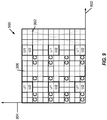
- FIG. 9 is a resource grid 900, depicting an example assignment of UE-RS transmission resources for a subframe including a downlink pilot time slot (DwPTS) with 11-12 symbols.
- resource elements marked "C” may be assigned to reference signals such as the CRS.
- the last three symbols (marked as area 902) may not be available for UE-RS.
- UE-RS may be allocated to two antenna port sets (regions labeled U1 and U2), each including two antenna ports.
- the antenna ports in an antenna port set may occupy the same two contiguous REs but may maintain orthogonality by code division multiplexing their transmissions.
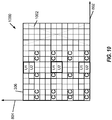
- FIG. 10 is a resource grid 1000, depicting an example assignment of UE-RS transmission resources for a subframe including a DwPTS with 9-10 symbols.
- resources labeled U1 and U2 may be shared by two CDMed antenna ports (in a given antenna port set) each.
- the region marked 1002 may not available for UE-RS transmission because of the pilot time slot.
- FIG. 11 shows a resource grid 1100, depicting an example assignment of UE-RS transmission resources for normal CP subframe for a rank 5-8 MU-MIMO system.
- the resource grid 1100 shows REs 306 being assigned to four different of resources: U5, U6, U7 and U8.
- Each group may correspond to resources assigned to an antenna port set (e.g., comprising two antenna ports each). It may be noticed that the bandwidth allocated to antenna port sets using resources U5, U6, U7 and U8 (e.g., area 1102) is different in two slots within the subframe.
- resources U5 and U6 may be assigned to an antenna port set comprising four antenna ports, all code division orthogonally multiplexed with each other.
- other combinations of antenna port sets and number of antennas in each antenna port set may also be possible.
- some mapping techniques designed below may achieve orthogonality of transmission between different antenna ports, either in the FDM manner or in the CDM manner.
- code division multiplexed antenna ports which share the same set of UE-RS REs 306 (e.g., U1 to U8 depicted in FIGs. 8 to 11 ), may be logically grouped as an antenna port set.
- the antenna ports in the same antenna port set may use the same random sequence after mapping. In some designs, across different antenna port sets, different random sequences may be used.
- repetition of the same random sequence over different PRBs may be avoided to alleviate any peak-to-average-power-ratio (PAPR) concerns.
- PAPR peak-to-average-power-ratio
- the UE-RS mapping may be dependent on PRB locations of the assigned PDSCH, but the PRB index may be bandwidth agnostic, similar to the CRS mapping case. In one aspect, such designs may maintain orthogonality of UE-RS transmissions of multiple cells involved in serving one UE 120.
- a different sequence may be used for UE-RS resource assignments.
- Eq. (18) the following notation is used: c init is the initialized sequence, the function f ( ) denotes a functional dependency, N ID ServingCell is an identification of a service cell in which a UE 120 is operating, n s represents a slot number and l is the symbol index of the actual symbol locations of UE-RS (instead of the ordered UE-RS symbol occurrences).
- c init is the initialized sequence
- the function f ( ) denotes a functional dependency
- N ID ServingCell is an identification of a service cell in which a UE 120 is operating
- n s represents a slot number
- l is the symbol index of the actual symbol locations of UE-RS (instead of the ordered UE-RS symbol occurrences).
- MaxNumAntPortSets may be assumed in constructing the interleaving structure. MaxNumAntPortSets is an interleaver design parameter, which does not have to correspond to the actual number of antenna port sets being used. MaxNumAntPortSets may be smaller or larger than the actual number of antenna port sets being used.
- MaxNumAntPortSets 1 may be assumed, irrespective of the number of antenna port sets being used, in which case, the same random sequence values are used for every antenna port set; in other words, the antenna port sets are not differentiated by the random sequences.
- Other interleaving designs are possible.
- the eNB 110 and UEs 120 may share (either explicitly through signaling or implicitly) the interleaving option used.
- AntPortSetIndex is the index of the antenna port set
- MaxNumAntPortSets is the max number of antenna port sets supported on a per UE basis, or on a per cell basis, or by specification (e.g., hardcoded by 4).
- the ceiling operation may also possible in Eq. (3).
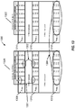
- FIG. 12 depicts an example resource mapping 1200 generated according to Eqs. (18) to (22).
- the resource mapping 1200 shows mapping of transmission resources to antenna port set 1 (table 1220) and antenna port set 2 (table 1222) at symbol locations k1, k2, k3 and k4.
- bandwidth is assigned to the receiving UE 120 in three PRBs: n PRB,1 , n PRB,2 and n PRB.3 , listed in rows 1208, 1210 and 1212 in table 1220 and rows 1214, 1216 and 1218 in table 1222, respectively.
- the three PRBs are non-contiguous.
- 3REs per RB per symbol are assigned to UE-RS.
- a separation of 1 RB (or 2 RBs) in assignment may imply an offset of 12 (or 18), as shown by entries 1201.
- the following aspects of the resource mapping performed according to Eqs. (18) to (22) may be evident.
- the resource mapping 1200 is not contiguous across n PRB s.
- the entries in the circled area 1202 change from "99" at the end of n PRB,1 (row 1208) to "107” at the beginning of the next PRB n PRB,2 (row 1210). Similar non-contiguity may be noticed in other entries for both antenna port sets, e.g., 111 to 125 for antenna port set 1 in table 1220, and 100 to 108 and 112 to 106 for antenna port set 2 in table 1222.
- the resource mapping 1200 "interleaves" resource assignments for antenna port set 1 and antenna port set 2. For example, entries “125” and “127” of antenna port set 1, indicated by area 1204, interleave with the entry "126" in the corresponding symbol and n PRB for the antenna port set 2.
- the same set of samples may be used across different symbols, for the same antenna port set.
- area 1206 shows that the same offset values "125,” “127” and “129” are used for symbols k3 and k4. This feature may be seen in all entries, for each symbol k1, k2, k3 and k4 and for each PRB.
- FIG. 13 depicts an example resource mapping 1300 generated according to Eqs. (24) to (28).
- the resource mapping 1300 may be similar to the resource mapping 1200 depicted in FIG. 12 in certain aspects.
- Table 1320 may correspond to antenna port set 1 and table 1322 may correspond to antenna port set 2.
- bandwidth is assigned to the receiving UE 120 in three PRBs: n PRB,1 , n PRB,2 and n PRB.3 , listed in rows 1308, 1310 and 1312 in table 1320 and rows 1314, 1316 and 1318 in table 1322, respectively.
- the three PRBs are non-contiguous.
- 3REs per RB per symbol are assigned to UE-RS.
- the resources are assumed to be assigned to two antenna port sets at symbol locations k1, k2, k3 and k4.
- the resource mapping 1300 may be seen to be different from the resource mapping 1200 as follows. Because a bandwidth agnostic PRB index may be used to derive offsets (see, e.g., Eq. (28) where n PRB is bandwidth agnostic), a separation of 1 RB (or 2RBs) between n PRB s, e.g., as shown in area 1301, results in an offset of 6 (or 9) RBs, e.g., between corresponding entries in rows 1308 and 1310. Furthermore, while different initializations may be used at the beginning of each symbol (see, e.g., Eq.
- the same offsets may be used in the same n PRB for each symbol across the antenna port sets, as illustrated by entries 1304, corresponding to row 1312 of table 1320 and row 1318 of table 1322, which may be identical for each symbol k1, k2, k3, k4 in each antenna port set (tables 1320 and 1320).
- the resource mapping 1300 may be seen to achieve certain characteristics also seen in the resource mapping 1200.
- the resource mapping 1300 may not be contiguous across n PRB s (e.g., as seen by entries 1302).
- antenna port set index dependent and symbol dependent initializations are used for the resource mapping 1300, it will be appreciated that the fixed offsets for each symbols may still result in non-contiguous, randomized allocation of transmission resources to UE-RS, as in the case of the resource mapping 1200.
- FIG. 14 is a flow chart representation of a process 1400 of wireless communication.
- the process 1400 may be implemented at the eNB 110.
- one or more antenna port sets may be formed.
- An antenna port set may comprise a logical group of two or more antenna ports.
- An antenna port set index may be assigned to a group of antennas of an antenna port set.
- the decision to assign antenna port indices may be performed by the eNB 110 and communicated to UEs 120.
- antenna port set assignments may be decided a priori and may be known to both the eNB 110 and UEs 120.
- transmission resources are allocated to a UE-RS based at least in part on an antenna port set index.
- the allocation may be a function of the antenna port set index.
- the allocation of transmission resources may be performed using various possible design alternatives discussed herein.
- the mapping, as disclosed in Eq. (18) to Eq. (23) may be used.
- the resulting resource mapping may be similar in aspects to the resource mapping 1200, discussed with respect to FIG. 12 .
- the mapping, as disclosed in Eq. (24) to Eq. (28) may be used.
- the resulting resource mapping may be similar in aspects to the resource mapping 1300, discussed with respect to FIG. 13 .
- FIG. 15 is a block diagram representation of an apparatus 1500 for wireless communication.
- the apparatus 1500 may, for example, be implemented at an eNB 110.
- the apparatus 1500 comprises a module 1502 for forming one or more antenna port sets.
- An antenna port set may comprise a logical group of two or more antenna ports.
- An antenna port set index may be assigned to a group of antennas of an antenna port set.
- the module 1502 may assign an antenna port index as discussed with respect to the operation 1402.
- the apparatus 1500 may comprise a module 1504 for allocating transmission resources to a user equipment reference signal based at least in part on an antenna port set index. In some designs, the allocation may be a function of the antenna port set index.
- the module 1504 may implement operation 1404 according to various design options discussed herein.
- FIG. 16 is a flow chart representation of a process 1600 of wireless communication.
- the process 1600 may be implemented at, for example, a UE 120.
- an assignment of an antenna port index may be received.
- An antenna port set may comprise a logical group of two or more antenna ports.
- the assignment may be received as a message from the eNB 110.
- the UE 120 may receive additional parameters, such as MaxNumAntPortSets, which may be used by the UE 120 in calculation of UE-RS assignments.
- these parameters, such as MaxNumAntPortSets and the antenna port set index may be known to the UE 120 a priori, such as, for example, a boot option.
- a transmission of a UE-RS may be received.
- the transmission of the UE-RS may be based at least in part on the antenna port set index. In some designs, the transmission may be a function of the antenna port set index.
- the UE-RS may be received in accordance with one or more of several design options discussed herein.
- the UE 120 may initialize a sequence and compute UE-RS resource locations by computing consistent with the design options disclosed herein. Subsequent to receiving a UE-RS transmission, the UE 120 may analyze the received signal and send a report to the eNB 110 based on the analysis.
- FIG. 17 is a block diagram representation of an apparatus 1700 for wireless communication.
- the apparatus 1700 may, for example, be implemented at a UE 120.
- the apparatus 1700 comprises a module 1702 for receiving an assignment of an antenna port index.
- An antenna port set may comprise a logical group of two or more antenna ports.
- the module 1702 may receive the assignment of the antenna port index as discussed with respect to the operation 1602.
- the apparatus 1700 may further comprise a module 1704 for receiving transmission of a user equipment reference signal (UE-RS).
- UE-RS user equipment reference signal
- the transmission may be based at least in part on the antenna port set index.
- the transmision may be a function of the antenna port set index.
- the module 1704 may implement operation 1604 according to various design options discussed herein.
- mapping transmission resources to UE-RS transmissions are disclosed. Some disclosed techniques include initializing a random sequence at the beginning of a symbol and calculating a fixed offset to physical resources (e.g., REs 306) to assign to UE-RS transmissions. Some disclosed techniques include initializing a fixed sequence at the beginning of a symbol, and calculating a random offset to physical resources to assign to UE-RS transmissions. The disclosed mappings may achieve frequency and/or code division orthogonalization between signals transmitted from antenna ports in an antenna port set. It may further be appreciated that, in some designs, sequence initialization and mapping may be performed at UEs 120. In one aspect, local calculations of UE-RS transmission locations may assist the UE 120, in receiving UE-RS transmissions without a need to receive explicit UE-RS location information from the eNB 110.
- the disclosed techniques may result in a density of UE-RS mapping, which may change between slots containing UE-RS.
- UE-RS mapping may depend on a CP type for a subframe.
- UE-RS mapping may depend on a type of sub-frame (e.g., normal CP, DwPTS, relaying backhaul subframe, etc.).
- exemplary is used herein to mean serving as an example, instance, or illustration. Any aspect or design described herein as “exemplary” is not necessarily to be construed as preferred or advantageous over other aspects or designs.
- DSP digital signal processor
- ASIC application specific integrated circuit
- FPGA field programmable gate array
- a general purpose processor may be a microprocessor, but in the alternative, the processor may be any conventional processor, controller, microcontroller, or state machine.
- a processor may also be implemented as a combination of computing devices, e.g., a combination of a DSP and a microprocessor, a plurality of microprocessors, one or more microprocessors in conjunction with a DSP core, or any other such configuration.
- the functions described may be implemented in hardware, software, firmware, or any combination thereof. If implemented in software, the functions may be stored on or encoded as one or more instructions or code on a computer-readable medium.
- Computer-readable media includes computer storage media. Storage media may be any available media that can be accessed by a computer. By way of example, and not limitation, such computer-readable media can comprise RAM, ROM, EEPROM, CD-ROM or other optical disk storage, magnetic disk storage or other magnetic storage devices, or any other medium that can be used to carry or store desired program code in the form of instructions or data structures and that can be accessed by a computer.
- Disk and disc includes compact disc (CD), laser disc, optical disc, digital versatile disc (DVD), floppy disk and blu-ray disc where disks usually reproduce data magnetically, while discs reproduce data optically with lasers. Combinations of the above should also be included within the scope of computer-readable media.
Landscapes
- Engineering & Computer Science (AREA)
- Signal Processing (AREA)
- Computer Networks & Wireless Communication (AREA)
- Mobile Radio Communication Systems (AREA)
- Radio Transmission System (AREA)
Applications Claiming Priority (4)
| Application Number | Priority Date | Filing Date | Title |
|---|---|---|---|
| US25193909P | 2009-10-15 | 2009-10-15 | |
| US12/903,659 US9432164B2 (en) | 2009-10-15 | 2010-10-13 | Method and apparatus for reference signal sequence mapping in wireless communication |
| EP10770685.5A EP2489147B1 (de) | 2009-10-15 | 2010-10-15 | Verfahren und vorrichtung zur referenzsignalen-ressourcenzuweisung |
| PCT/US2010/052962 WO2011047351A2 (en) | 2009-10-15 | 2010-10-15 | Method and apparatus for reference signal sequence mapping in wireless communication |
Related Parent Applications (1)
| Application Number | Title | Priority Date | Filing Date |
|---|---|---|---|
| EP10770685.5A Division EP2489147B1 (de) | 2009-10-15 | 2010-10-15 | Verfahren und vorrichtung zur referenzsignalen-ressourcenzuweisung |
Publications (2)
| Publication Number | Publication Date |
|---|---|
| EP3657722A1 true EP3657722A1 (de) | 2020-05-27 |
| EP3657722B1 EP3657722B1 (de) | 2023-07-19 |
Family
ID=43857855
Family Applications (2)
| Application Number | Title | Priority Date | Filing Date |
|---|---|---|---|
| EP19203303.3A Active EP3657722B1 (de) | 2009-10-15 | 2010-10-15 | Verfahren und vorrichtung für die zuordnung von referenzsignalsequenzen in der drahtlosen kommunikation |
| EP10770685.5A Active EP2489147B1 (de) | 2009-10-15 | 2010-10-15 | Verfahren und vorrichtung zur referenzsignalen-ressourcenzuweisung |
Family Applications After (1)
| Application Number | Title | Priority Date | Filing Date |
|---|---|---|---|
| EP10770685.5A Active EP2489147B1 (de) | 2009-10-15 | 2010-10-15 | Verfahren und vorrichtung zur referenzsignalen-ressourcenzuweisung |
Country Status (9)
| Country | Link |
|---|---|
| US (1) | US9432164B2 (de) |
| EP (2) | EP3657722B1 (de) |
| JP (2) | JP5698248B2 (de) |
| KR (1) | KR101380874B1 (de) |
| CN (1) | CN102742208B (de) |
| ES (1) | ES2772034T3 (de) |
| HU (1) | HUE047355T2 (de) |
| TW (1) | TW201134171A (de) |
| WO (1) | WO2011047351A2 (de) |
Families Citing this family (42)
| Publication number | Priority date | Publication date | Assignee | Title |
|---|---|---|---|---|
| KR101663616B1 (ko) * | 2009-04-29 | 2016-10-07 | 엘지전자 주식회사 | 다중 안테나 무선 통신 시스템에서 참조 신호 시퀀스 생성 방법 및 이를 위한 장치 |
| EP2282418A3 (de) * | 2009-06-23 | 2011-03-09 | Alcatel Lucent | Station mit mindestens zwei Sendeantennen und Sendeverfahren dafür |
| US8948097B2 (en) * | 2009-09-30 | 2015-02-03 | Qualcomm Incorporated | UE-RS sequence initialization for wireless communication systems |
| US8923905B2 (en) * | 2009-09-30 | 2014-12-30 | Qualcomm Incorporated | Scrambling sequence initialization for coordinated multi-point transmissions |
| US8908617B2 (en) * | 2009-12-31 | 2014-12-09 | Samsung Electronics Co., Ltd. | Uplink demodulation reference signal design for MIMO transmission |
| CN102118825B (zh) * | 2009-12-31 | 2013-12-04 | 华为技术有限公司 | 实现多点联合传输的方法、终端及系统 |
| US8638719B2 (en) * | 2010-12-02 | 2014-01-28 | Nokia Corporation | Inter-cell interference coordination of multiple transmission ranks |
| WO2012148443A1 (en) * | 2011-04-29 | 2012-11-01 | Intel Corporation | System and method of rank adaptation in mimo communication system |
| CN102811107B (zh) | 2011-06-03 | 2016-03-30 | 华为技术有限公司 | 导频序列配置方法和网络设备 |
| CN104901788B (zh) | 2011-08-05 | 2018-08-21 | 华为技术有限公司 | 一种导频信号发送方法和设备 |
| US8693420B2 (en) | 2011-08-10 | 2014-04-08 | Futurewei Technologies, Inc. | System and method for signaling and transmitting uplink reference signals |
| CA2844932C (en) * | 2011-08-12 | 2021-06-08 | Interdigital Patent Holdings, Inc. | Method and apparatus for multiple-input multiple-output operation |
| KR102066278B1 (ko) | 2011-11-07 | 2020-01-15 | 애플 인크. | 참조신호 전송 방법과 장치, 및 그를 이용한 채널 추정 방법 및 장치 |
| US9590709B2 (en) | 2011-12-23 | 2017-03-07 | Nokia Solutions And Networks Oy | Methods, apparatuses, and computer-readable storage media for performing multidimensional beamforming |
| EP2830234B1 (de) | 2012-03-19 | 2018-08-01 | Panasonic Intellectual Property Corporation of America | Sendevorrichtung, sendeverfahren, empfangsvorrichtung und empfangsverfahren |
| US8971881B2 (en) * | 2012-03-23 | 2015-03-03 | Google Technology Holdings LLC | Radio link monitoring in a wireless communication device for an enhanced control channel |
| US9078109B2 (en) * | 2012-04-09 | 2015-07-07 | Intel Corporation | Frame structure design for new carrier type (NCT) |
| US8923207B2 (en) | 2012-05-17 | 2014-12-30 | Industrial Technology Research Institute | Method for initializing sequence of reference signal and base station using the same |
| CN103581932B (zh) * | 2012-08-09 | 2019-04-05 | 中兴通讯股份有限公司 | 一种导频测量方法及装置 |
| US9651653B2 (en) * | 2012-12-24 | 2017-05-16 | Qualcomm Incorporated | Positioning reference signal (PRS) generation for multiple transmit antenna systems |
| US9882691B2 (en) * | 2013-02-14 | 2018-01-30 | Lg Electronics Inc. | Method and apparatus for providing antenna configuration information for massive multiple input multiple output in a wireless communication system |
| KR102201755B1 (ko) * | 2013-06-25 | 2021-01-12 | 엘지전자 주식회사 | 무선 통신 시스템에서 적응적 안테나 스케일링을 위한 프리코딩 방법 및 이를 위한 장치 |
| US10687218B2 (en) * | 2013-12-03 | 2020-06-16 | Qualcomm Incorporated | Power metric optimization and uplink DM-RS design for LTE/LTE-A uplink transmissions in unlicensed spectrum |
| CN105052187B (zh) * | 2013-12-16 | 2020-03-20 | 华为技术有限公司 | 导频信号的传输方法、基站及用户设备 |
| EP3140921B1 (de) * | 2014-05-08 | 2019-12-25 | Telefonaktiebolaget LM Ericsson (publ) | Strahlformung mit einer antennenanordnung |
| WO2016056805A1 (ko) * | 2014-10-09 | 2016-04-14 | 엘지전자 주식회사 | 매시브 mimo를 지원하는 무선 통신 시스템에서 참조 신호의 생성 방법 |
| DE112015006633T5 (de) * | 2015-06-19 | 2018-03-08 | Hytera Communications Corp., Ltd. | Gleichkanal-Netzwerkverfahren und eine Vorrichtung basierend auf einem Trunking-Dienst |
| CN106411473B (zh) * | 2015-07-27 | 2019-07-19 | 电信科学技术研究院 | 一种参考信号映射方法及装置 |
| CN107181578B (zh) * | 2016-03-10 | 2020-01-14 | 电信科学技术研究院 | 一种参考信号映射方法及装置 |
| CN107592676B (zh) * | 2016-07-08 | 2023-05-02 | 中兴通讯股份有限公司 | 一种数据生成方法及装置、发射机、终端 |
| US11570577B2 (en) * | 2016-08-12 | 2023-01-31 | Sony Corporation | Location server, infrastructure equipment, communications device and methods for the use of supplementary positioning reference signals |
| JP6925385B2 (ja) * | 2016-12-07 | 2021-08-25 | 三菱電機株式会社 | 送信装置、通信システム、制御回路およびプログラム |
| CN111148246B (zh) * | 2017-02-03 | 2021-02-23 | Oppo广东移动通信有限公司 | 信息传输方法、装置和存储介质 |
| WO2018184169A1 (en) | 2017-04-06 | 2018-10-11 | Qualcomm Incorporated | Multiple user port loading indication |
| DE112018000222T5 (de) | 2017-05-05 | 2019-09-05 | Intel IP Corporation | Erzeugen und Zuordnen von RS(Referenz-Signal)-Sequenz und Vorkodiererzuteilung für NR (Neuer Funk) |
| CN109600855B (zh) * | 2017-09-30 | 2021-05-18 | 华为技术有限公司 | 时频资源配置方法及设备 |
| WO2019088694A1 (ko) * | 2017-10-31 | 2019-05-09 | 엘지전자 주식회사 | 무선 통신 시스템에서 시퀀스의 초기값을 결정하기 위한 방법 및 이를 위한 장치 |
| US11082279B2 (en) | 2018-09-27 | 2021-08-03 | At&T Intellectual Property I, L.P. | Facilitation of reduction of peak to average power ratio for 5G or other next generation network |
| US10659270B2 (en) | 2018-10-10 | 2020-05-19 | At&T Intellectual Property I, L.P. | Mapping reference signals in wireless communication systems to avoid repetition |
| US11418992B2 (en) | 2018-11-02 | 2022-08-16 | At&T Intellectual Property I, L.P. | Generation of demodulation reference signals in advanced networks |
| KR20210119497A (ko) * | 2019-01-28 | 2021-10-05 | 소니그룹주식회사 | 다중 안테나 패널 업링크 통신 |
| CN121532991A (zh) * | 2023-05-19 | 2026-02-13 | 华为技术有限公司 | 通信方法和通信装置 |
Family Cites Families (54)
| Publication number | Priority date | Publication date | Assignee | Title |
|---|---|---|---|---|
| US5887262A (en) | 1996-04-19 | 1999-03-23 | Nokia Mobile Phones Limited | Smart antenna backwards compatibility in digital cellular systems |
| JP3529621B2 (ja) | 1997-05-12 | 2004-05-24 | 株式会社東芝 | ルータ装置、データグラム転送方法及び通信システム |
| US6779146B1 (en) | 1999-04-05 | 2004-08-17 | Cisco Technology, Inc. | ARQ for point to point links |
| KR100442603B1 (ko) | 2001-03-20 | 2004-08-02 | 삼성전자주식회사 | 고속 패킷 데이터 전송 이동통신시스템에서 패킷 데이터채널 및 패킷 데이터 제어 채널을 스크램블링하기 위한장치 및 방법 |
| KR100762602B1 (ko) | 2001-10-08 | 2007-10-01 | 삼성전자주식회사 | 부호분할다중접속 이동통신시스템에서 기준 타이밍생성장치 및 방법 |
| CN1167218C (zh) | 2001-10-23 | 2004-09-15 | 北京邮电大学 | 无线通信系统中应用智能天线和联合检测的接收机结构及其方法 |
| ES2197794B1 (es) | 2002-01-18 | 2005-03-16 | Diseño De Sistemas En Silicio, S.A | Procedimiento de transmision de datos para un sistema multiusuario de transmision digital de datos punto a multipunto. |
| JP4372626B2 (ja) | 2004-06-28 | 2009-11-25 | ヤマハ発動機株式会社 | 情報通信装置及び情報通信方法 |
| JPWO2007015480A1 (ja) * | 2005-08-03 | 2009-02-19 | 日本電気株式会社 | シリアル信号伝送方式 |
| KR100759002B1 (ko) | 2005-10-21 | 2007-09-17 | 삼성전자주식회사 | 디지털 방송 신호를 처리하여 송신하는 디지털 방송 송신시스템 및 그 방법 |
| WO2008103317A2 (en) | 2007-02-16 | 2008-08-28 | Interdigital Technology Corporation | Precoded pilot transmission for multi-user and single user mimo communications |
| US7965689B2 (en) * | 2007-05-14 | 2011-06-21 | Motorola Mobility, Inc. | Reference sequence construction for fast cell search |
| CN101325741B (zh) | 2007-06-14 | 2012-12-12 | Nxp股份有限公司 | 用于操作多用户多输入多输出(mu-mimo)无线通信系统的方法和系统 |
| EP2903178B1 (de) | 2007-06-27 | 2019-06-19 | Unwired Planet International Limited | Verfahren und Anordnungen in einem Telekommunikationssystem mit Unterstützung von MU-MIMO und SU-MIMO |
| US8711916B2 (en) | 2007-07-27 | 2014-04-29 | Intel Corporation | Tap initialization of equalizer based on estimated channel impulse response |
| EP2198664B1 (de) | 2007-08-31 | 2012-10-17 | Koninklijke Philips Electronics N.V. | Erweiterte mehrbenutzerübertragung |
| US8848913B2 (en) | 2007-10-04 | 2014-09-30 | Qualcomm Incorporated | Scrambling sequence generation in a communication system |
| US9648493B2 (en) | 2007-11-16 | 2017-05-09 | Qualcomm Incorporated | Using identifiers to establish communication |
| EP2075973B1 (de) * | 2007-12-28 | 2018-08-15 | Telefonaktiebolaget LM Ericsson (publ) | Identifizierung einer sequenz von empfangener referenzsymbolen |
| WO2009116769A1 (en) * | 2008-03-17 | 2009-09-24 | Lg Electronics Inc. | Method of transmitting reference signal and transmitter using the same |
| US9544776B2 (en) | 2008-03-25 | 2017-01-10 | Qualcomm Incorporated | Transmission and reception of dedicated reference signals |
| US20090268910A1 (en) * | 2008-04-28 | 2009-10-29 | Samsung Electronics Co., Ltd. | Apparatus and method for initialization of a scrambling sequence for a downlink reference signal in a wireless network |
| CN101340228B (zh) | 2008-08-07 | 2014-05-28 | 中兴通讯股份有限公司南京分公司 | 一种参考信号的传输方法 |
| US20100041350A1 (en) * | 2008-08-13 | 2010-02-18 | Samsung Electronics, Co., Ltd. | Uplink transmissions with two antenna ports |
| CN102224687B (zh) * | 2008-09-22 | 2014-10-29 | 岩星比德科有限公司 | 用于pucch的空间代码传送分集的方法和系统 |
| WO2010034349A1 (en) | 2008-09-26 | 2010-04-01 | Nokia Siemens Networks Oy | Control signaling in system supporting relayed connections |
| US8737507B2 (en) * | 2008-11-03 | 2014-05-27 | Telefonaktiebolaget L M Ericsson (Publ) | Method for transmitting of reference signals and determination of precoding matrices for multi-antenna transmission |
| KR101632208B1 (ko) * | 2008-11-07 | 2016-06-21 | 엘지전자 주식회사 | 참조 신호 전송 방법 |
| US9215035B2 (en) | 2008-12-08 | 2015-12-15 | Lg Electronics Inc. | Method of transmitting and receiving physical downlink shared channel in wireless communication system |
| CN102246447A (zh) | 2008-12-10 | 2011-11-16 | 松下电器产业株式会社 | 无线通信终端装置、无线通信基站装置及信号扩频方法 |
| US8780829B2 (en) | 2008-12-11 | 2014-07-15 | Lg Electronics Inc. | Method for transmitting and receiving a comp reference signal in a multi-cell environment |
| WO2010082735A2 (en) | 2009-01-19 | 2010-07-22 | Lg Electronics Inc. | Method of transmitting signal in a wireless system |
| US9094167B2 (en) | 2009-02-02 | 2015-07-28 | Samsung Electronics Co., Ltd. | System and method for multi-user and multi-cell MIMO transmissions |
| US9647810B2 (en) * | 2009-03-17 | 2017-05-09 | Samsung Electronics Co., Ltd. | Method and system for mapping pilot signals in multi-stream transmissions |
| US8369429B2 (en) | 2009-03-18 | 2013-02-05 | Lg Electronics Inc. | Method and apparatus for transmitting precoding matrix index in a wireless communication system using CoMP scheme |
| US8953563B2 (en) * | 2009-04-24 | 2015-02-10 | Samsung Electronics Co., Ltd. | Method and system for multi-layer beamforming |
| KR101568274B1 (ko) | 2009-05-29 | 2015-11-20 | 삼성전자주식회사 | 협력 멀티-포인트 송신을 위한 클러스터링 방법 및 통신 장치 |
| CN101931485B (zh) | 2009-06-19 | 2014-02-12 | 北京三星通信技术研究有限公司 | 一种专用参考信号生成方法和装置 |
| KR101642311B1 (ko) | 2009-07-24 | 2016-07-25 | 엘지전자 주식회사 | CoMP 참조신호 송수신 방법 |
| KR101710204B1 (ko) * | 2009-07-28 | 2017-03-08 | 엘지전자 주식회사 | 다중 입출력 통신 시스템에서 채널측정을 위한 기준신호의 전송 방법 및 그 장치 |
| US8923216B2 (en) | 2009-07-30 | 2014-12-30 | Qualcomm Incorporated | Robust decoding of CoMP transmissions |
| US9344953B2 (en) | 2009-08-17 | 2016-05-17 | Nokia Technologies Oy | Apparatus and method for initialization and mapping of reference signals in a communication system |
| US8576692B2 (en) | 2009-09-10 | 2013-11-05 | Qualcomm Incorporated | Transmission of UE-specific reference signal for wireless communication |
| US8923905B2 (en) | 2009-09-30 | 2014-12-30 | Qualcomm Incorporated | Scrambling sequence initialization for coordinated multi-point transmissions |
| US8948097B2 (en) | 2009-09-30 | 2015-02-03 | Qualcomm Incorporated | UE-RS sequence initialization for wireless communication systems |
| US8634362B2 (en) | 2009-10-01 | 2014-01-21 | Qualcomm Incorporated | Reference signals for multi-user MIMO communication |
| US8437300B2 (en) | 2009-10-12 | 2013-05-07 | Samsung Electronics Co., Ltd | Method and system of multi-layer beamforming |
| EP2517491A4 (de) | 2009-12-25 | 2016-06-01 | Nokia Solutions & Networks Oy | Mapping von referenzsignalen für mehrzellenübertragung |
| EP2568649B1 (de) | 2010-05-04 | 2020-10-28 | LG Electronics Inc. | Verfahren und vorrichtung zur ressourcenzuweisung für datenübertragungen mit downlink-bestätigungsantwort in einem drahtlosen kommunikationssystem |
| US10187859B2 (en) | 2011-02-14 | 2019-01-22 | Qualcomm Incorporated | Power control and user multiplexing for heterogeneous network coordinated multipoint operations |
| JP6324954B2 (ja) | 2012-06-18 | 2018-05-16 | サムスン エレクトロニクス カンパニー リミテッド | 協調マルチポイント送信のための非周期的及び周期的csiフィードバックモード |
| US20130343299A1 (en) | 2012-06-21 | 2013-12-26 | Samsung Electronics Co., Ltd | Method for cqi feedback without spatial feedback (pmi/ri) for tdd coordinated multi-point and carrier aggregation scenarios |
| US10433159B2 (en) | 2012-08-03 | 2019-10-01 | Texas Instruments Incorporated | Uplink signaling for cooperative multipoint communication |
| US9973315B2 (en) | 2012-09-28 | 2018-05-15 | Intel Corporation | Systems and methods for semi-persistent scheduling of wireless communications |
-
2010
- 2010-10-13 US US12/903,659 patent/US9432164B2/en active Active
- 2010-10-15 EP EP19203303.3A patent/EP3657722B1/de active Active
- 2010-10-15 ES ES10770685T patent/ES2772034T3/es active Active
- 2010-10-15 KR KR1020127012556A patent/KR101380874B1/ko active Active
- 2010-10-15 JP JP2012534424A patent/JP5698248B2/ja active Active
- 2010-10-15 EP EP10770685.5A patent/EP2489147B1/de active Active
- 2010-10-15 HU HUE10770685A patent/HUE047355T2/hu unknown
- 2010-10-15 WO PCT/US2010/052962 patent/WO2011047351A2/en not_active Ceased
- 2010-10-15 CN CN201080045846.7A patent/CN102742208B/zh active Active
- 2010-10-15 TW TW099135271A patent/TW201134171A/zh unknown
-
2015
- 2015-02-12 JP JP2015025581A patent/JP6158237B2/ja active Active
Non-Patent Citations (3)
| Title |
|---|
| CMCC: "Discussions on DM-RS Design for LTE-A", 3GPP DRAFT; R1-092189 DISCUSSIONS ON DM-RS DESIGN FOR LTE-A_REVISED, 3RD GENERATION PARTNERSHIP PROJECT (3GPP), MOBILE COMPETENCE CENTRE ; 650, ROUTE DES LUCIOLES ; F-06921 SOPHIA-ANTIPOLIS CEDEX ; FRANCE, no. San Francisco, USA; 20090504, 4 May 2009 (2009-05-04), XP050339620 * |
| CMCC: "Discussions on DM-RS Design with Rank Grouping", 3GPP DRAFT; R1-092823 DISCUSSIONS ON DM-RS DESIGN WITH RANK GROUPING, 3RD GENERATION PARTNERSHIP PROJECT (3GPP), MOBILE COMPETENCE CENTRE ; 650, ROUTE DES LUCIOLES ; F-06921 SOPHIA-ANTIPOLIS CEDEX ; FRANCE, vol. RAN WG1, no. Los Angeles; 20090629 - 20090703, 27 June 2009 (2009-06-27), XP050597565 * |
| NTT DOCOMO: "DL CSI-RS Design for LTE-Advanced", 3GPP DRAFT; R1-094339 DL CSI-RS FOR LTE-A_V2, 3RD GENERATION PARTNERSHIP PROJECT (3GPP), MOBILE COMPETENCE CENTRE ; 650, ROUTE DES LUCIOLES ; F-06921 SOPHIA-ANTIPOLIS CEDEX ; FRANCE, no. Miyazaki; 20091012, 12 October 2009 (2009-10-12), XP050388791 * |
Also Published As
| Publication number | Publication date |
|---|---|
| WO2011047351A3 (en) | 2011-06-23 |
| KR20120093961A (ko) | 2012-08-23 |
| ES2772034T3 (es) | 2020-07-07 |
| US9432164B2 (en) | 2016-08-30 |
| HUE047355T2 (hu) | 2020-04-28 |
| EP3657722B1 (de) | 2023-07-19 |
| WO2011047351A2 (en) | 2011-04-21 |
| JP2015133719A (ja) | 2015-07-23 |
| EP2489147B1 (de) | 2019-11-13 |
| CN102742208A (zh) | 2012-10-17 |
| KR101380874B1 (ko) | 2014-04-02 |
| JP5698248B2 (ja) | 2015-04-08 |
| CN102742208B (zh) | 2015-11-25 |
| JP2013509042A (ja) | 2013-03-07 |
| EP2489147A2 (de) | 2012-08-22 |
| TW201134171A (en) | 2011-10-01 |
| JP6158237B2 (ja) | 2017-07-05 |
| US20110249767A1 (en) | 2011-10-13 |
Similar Documents
| Publication | Publication Date | Title |
|---|---|---|
| EP2489147B1 (de) | Verfahren und vorrichtung zur referenzsignalen-ressourcenzuweisung | |
| EP2484033B1 (de) | Initialisierung von ue-rs sequenzen für drahtlose kommunikationssysteme | |
| EP2548325B1 (de) | Benutzer-spezifisches suchraumkonzept zum mehrträgerbetrieb | |
| EP3740010B1 (de) | Schmalbandige partitionierung und effiziente ressourcenzuweisung für kostengünstige benutzervorrichtungen | |
| US9277566B2 (en) | Cross-subframe control channel design | |
| KR102067060B1 (ko) | 무선 통신 시스템에서 제어 정보의 전송 방법 및 장치 | |
| EP2779495B1 (de) | Verfahren und vorrichtung zur übertragung von steuerungsinformationen in einem drahtlosen kommunikationssystem | |
| EP2792096B1 (de) | Verfahren zur erzeugung und übertragung von demodulationsreferenzsignalen | |
| EP2761959B1 (de) | Steuerkanalsystem und verfahren für drahtlose kommunikation | |
| CN102474493B (zh) | 在支持多天线的无线通信系统中传输下行链路基准信号的方法及装置 | |
| EP2777176B1 (de) | Steuerkanalerkennungsverfahren und -vorrichtung in einem mimo-system | |
| EP2847899B1 (de) | Verfahren und vorrichtung zum konfigurieren eines suchraums eines downlink-steuerkanals | |
| EP3447958A1 (de) | Design eines epdcch-suchraums | |
| WO2013077657A1 (ko) | 무선 통신 시스템에서 하향링크 제어 채널을 송수신하는 방법 및 장치 | |
| WO2008137963A2 (en) | Method and apparatus for multiplexing cdm pilot and fdm data | |
| WO2013147523A1 (ko) | 무선 통신 시스템에서 하향링크 제어 채널을 위한 자원을 할당하는 방법 및 이를 위한 장치 | |
| WO2014073928A1 (en) | Method and apparatus for transmitting downlink data | |
| CN103220103A (zh) | 增强物理下行控制信道的传输方法及装置 | |
| WO2013062205A1 (ko) | 무선 통신 시스템에서 기지국이 제어 채널을 위한 단말 특정 참조 신호를 송신하는 방법 및 이를 위한 장치 |
Legal Events
| Date | Code | Title | Description |
|---|---|---|---|
| PUAI | Public reference made under article 153(3) epc to a published international application that has entered the european phase |
Free format text: ORIGINAL CODE: 0009012 |
|
| STAA | Information on the status of an ep patent application or granted ep patent |
Free format text: STATUS: THE APPLICATION HAS BEEN PUBLISHED |
|
| AC | Divisional application: reference to earlier application |
Ref document number: 2489147 Country of ref document: EP Kind code of ref document: P |
|
| AK | Designated contracting states |
Kind code of ref document: A1 Designated state(s): AL AT BE BG CH CY CZ DE DK EE ES FI FR GB GR HR HU IE IS IT LI LT LU LV MC MK MT NL NO PL PT RO RS SE SI SK SM TR |
|
| STAA | Information on the status of an ep patent application or granted ep patent |
Free format text: STATUS: REQUEST FOR EXAMINATION WAS MADE |
|
| 17P | Request for examination filed |
Effective date: 20201124 |
|
| RBV | Designated contracting states (corrected) |
Designated state(s): AL AT BE BG CH CY CZ DE DK EE ES FI FR GB GR HR HU IE IS IT LI LT LU LV MC MK MT NL NO PL PT RO RS SE SI SK SM TR |
|
| GRAP | Despatch of communication of intention to grant a patent |
Free format text: ORIGINAL CODE: EPIDOSNIGR1 |
|
| STAA | Information on the status of an ep patent application or granted ep patent |
Free format text: STATUS: GRANT OF PATENT IS INTENDED |
|
| INTG | Intention to grant announced |
Effective date: 20220810 |
|
| GRAJ | Information related to disapproval of communication of intention to grant by the applicant or resumption of examination proceedings by the epo deleted |
Free format text: ORIGINAL CODE: EPIDOSDIGR1 |
|
| STAA | Information on the status of an ep patent application or granted ep patent |
Free format text: STATUS: REQUEST FOR EXAMINATION WAS MADE |
|
| INTC | Intention to grant announced (deleted) | ||
| GRAP | Despatch of communication of intention to grant a patent |
Free format text: ORIGINAL CODE: EPIDOSNIGR1 |
|
| STAA | Information on the status of an ep patent application or granted ep patent |
Free format text: STATUS: GRANT OF PATENT IS INTENDED |
|
| INTG | Intention to grant announced |
Effective date: 20230208 |
|
| GRAS | Grant fee paid |
Free format text: ORIGINAL CODE: EPIDOSNIGR3 |
|
| GRAA | (expected) grant |
Free format text: ORIGINAL CODE: 0009210 |
|
| STAA | Information on the status of an ep patent application or granted ep patent |
Free format text: STATUS: THE PATENT HAS BEEN GRANTED |
|
| AC | Divisional application: reference to earlier application |
Ref document number: 2489147 Country of ref document: EP Kind code of ref document: P |
|
| AK | Designated contracting states |
Kind code of ref document: B1 Designated state(s): AL AT BE BG CH CY CZ DE DK EE ES FI FR GB GR HR HU IE IS IT LI LT LU LV MC MK MT NL NO PL PT RO RS SE SI SK SM TR |
|
| REG | Reference to a national code |
Ref country code: GB Ref legal event code: FG4D |
|
| REG | Reference to a national code |
Ref country code: CH Ref legal event code: EP |
|
| REG | Reference to a national code |
Ref country code: DE Ref legal event code: R096 Ref document number: 602010068930 Country of ref document: DE |
|
| REG | Reference to a national code |
Ref country code: IE Ref legal event code: FG4D |
|
| REG | Reference to a national code |
Ref country code: NL Ref legal event code: FP |
|
| REG | Reference to a national code |
Ref country code: LT Ref legal event code: MG9D |
|
| REG | Reference to a national code |
Ref country code: AT Ref legal event code: MK05 Ref document number: 1590548 Country of ref document: AT Kind code of ref document: T Effective date: 20230719 |
|
| PG25 | Lapsed in a contracting state [announced via postgrant information from national office to epo] |
Ref country code: GR Free format text: LAPSE BECAUSE OF FAILURE TO SUBMIT A TRANSLATION OF THE DESCRIPTION OR TO PAY THE FEE WITHIN THE PRESCRIBED TIME-LIMIT Effective date: 20231020 |
|
| PG25 | Lapsed in a contracting state [announced via postgrant information from national office to epo] |
Ref country code: IS Free format text: LAPSE BECAUSE OF FAILURE TO SUBMIT A TRANSLATION OF THE DESCRIPTION OR TO PAY THE FEE WITHIN THE PRESCRIBED TIME-LIMIT Effective date: 20231119 |
|
| PG25 | Lapsed in a contracting state [announced via postgrant information from national office to epo] |
Ref country code: SE Free format text: LAPSE BECAUSE OF FAILURE TO SUBMIT A TRANSLATION OF THE DESCRIPTION OR TO PAY THE FEE WITHIN THE PRESCRIBED TIME-LIMIT Effective date: 20230719 Ref country code: RS Free format text: LAPSE BECAUSE OF FAILURE TO SUBMIT A TRANSLATION OF THE DESCRIPTION OR TO PAY THE FEE WITHIN THE PRESCRIBED TIME-LIMIT Effective date: 20230719 Ref country code: PT Free format text: LAPSE BECAUSE OF FAILURE TO SUBMIT A TRANSLATION OF THE DESCRIPTION OR TO PAY THE FEE WITHIN THE PRESCRIBED TIME-LIMIT Effective date: 20231120 Ref country code: NO Free format text: LAPSE BECAUSE OF FAILURE TO SUBMIT A TRANSLATION OF THE DESCRIPTION OR TO PAY THE FEE WITHIN THE PRESCRIBED TIME-LIMIT Effective date: 20231019 Ref country code: LV Free format text: LAPSE BECAUSE OF FAILURE TO SUBMIT A TRANSLATION OF THE DESCRIPTION OR TO PAY THE FEE WITHIN THE PRESCRIBED TIME-LIMIT Effective date: 20230719 Ref country code: LT Free format text: LAPSE BECAUSE OF FAILURE TO SUBMIT A TRANSLATION OF THE DESCRIPTION OR TO PAY THE FEE WITHIN THE PRESCRIBED TIME-LIMIT Effective date: 20230719 Ref country code: IS Free format text: LAPSE BECAUSE OF FAILURE TO SUBMIT A TRANSLATION OF THE DESCRIPTION OR TO PAY THE FEE WITHIN THE PRESCRIBED TIME-LIMIT Effective date: 20231119 Ref country code: HR Free format text: LAPSE BECAUSE OF FAILURE TO SUBMIT A TRANSLATION OF THE DESCRIPTION OR TO PAY THE FEE WITHIN THE PRESCRIBED TIME-LIMIT Effective date: 20230719 Ref country code: GR Free format text: LAPSE BECAUSE OF FAILURE TO SUBMIT A TRANSLATION OF THE DESCRIPTION OR TO PAY THE FEE WITHIN THE PRESCRIBED TIME-LIMIT Effective date: 20231020 Ref country code: FI Free format text: LAPSE BECAUSE OF FAILURE TO SUBMIT A TRANSLATION OF THE DESCRIPTION OR TO PAY THE FEE WITHIN THE PRESCRIBED TIME-LIMIT Effective date: 20230719 Ref country code: AT Free format text: LAPSE BECAUSE OF FAILURE TO SUBMIT A TRANSLATION OF THE DESCRIPTION OR TO PAY THE FEE WITHIN THE PRESCRIBED TIME-LIMIT Effective date: 20230719 |
|
| PG25 | Lapsed in a contracting state [announced via postgrant information from national office to epo] |
Ref country code: PL Free format text: LAPSE BECAUSE OF FAILURE TO SUBMIT A TRANSLATION OF THE DESCRIPTION OR TO PAY THE FEE WITHIN THE PRESCRIBED TIME-LIMIT Effective date: 20230719 |
|
| REG | Reference to a national code |
Ref country code: DE Ref legal event code: R097 Ref document number: 602010068930 Country of ref document: DE |
|
| PG25 | Lapsed in a contracting state [announced via postgrant information from national office to epo] |
Ref country code: ES Free format text: LAPSE BECAUSE OF FAILURE TO SUBMIT A TRANSLATION OF THE DESCRIPTION OR TO PAY THE FEE WITHIN THE PRESCRIBED TIME-LIMIT Effective date: 20230719 |
|
| PG25 | Lapsed in a contracting state [announced via postgrant information from national office to epo] |
Ref country code: SM Free format text: LAPSE BECAUSE OF FAILURE TO SUBMIT A TRANSLATION OF THE DESCRIPTION OR TO PAY THE FEE WITHIN THE PRESCRIBED TIME-LIMIT Effective date: 20230719 Ref country code: RO Free format text: LAPSE BECAUSE OF FAILURE TO SUBMIT A TRANSLATION OF THE DESCRIPTION OR TO PAY THE FEE WITHIN THE PRESCRIBED TIME-LIMIT Effective date: 20230719 Ref country code: ES Free format text: LAPSE BECAUSE OF FAILURE TO SUBMIT A TRANSLATION OF THE DESCRIPTION OR TO PAY THE FEE WITHIN THE PRESCRIBED TIME-LIMIT Effective date: 20230719 Ref country code: EE Free format text: LAPSE BECAUSE OF FAILURE TO SUBMIT A TRANSLATION OF THE DESCRIPTION OR TO PAY THE FEE WITHIN THE PRESCRIBED TIME-LIMIT Effective date: 20230719 Ref country code: DK Free format text: LAPSE BECAUSE OF FAILURE TO SUBMIT A TRANSLATION OF THE DESCRIPTION OR TO PAY THE FEE WITHIN THE PRESCRIBED TIME-LIMIT Effective date: 20230719 Ref country code: CZ Free format text: LAPSE BECAUSE OF FAILURE TO SUBMIT A TRANSLATION OF THE DESCRIPTION OR TO PAY THE FEE WITHIN THE PRESCRIBED TIME-LIMIT Effective date: 20230719 Ref country code: SK Free format text: LAPSE BECAUSE OF FAILURE TO SUBMIT A TRANSLATION OF THE DESCRIPTION OR TO PAY THE FEE WITHIN THE PRESCRIBED TIME-LIMIT Effective date: 20230719 |
|
| PLBE | No opposition filed within time limit |
Free format text: ORIGINAL CODE: 0009261 |
|
| STAA | Information on the status of an ep patent application or granted ep patent |
Free format text: STATUS: NO OPPOSITION FILED WITHIN TIME LIMIT |
|
| PG25 | Lapsed in a contracting state [announced via postgrant information from national office to epo] |
Ref country code: IT Free format text: LAPSE BECAUSE OF FAILURE TO SUBMIT A TRANSLATION OF THE DESCRIPTION OR TO PAY THE FEE WITHIN THE PRESCRIBED TIME-LIMIT Effective date: 20230719 Ref country code: MC Free format text: LAPSE BECAUSE OF FAILURE TO SUBMIT A TRANSLATION OF THE DESCRIPTION OR TO PAY THE FEE WITHIN THE PRESCRIBED TIME-LIMIT Effective date: 20230719 |
|
| REG | Reference to a national code |
Ref country code: CH Ref legal event code: PL |
|
| REG | Reference to a national code |
Ref country code: BE Ref legal event code: MM Effective date: 20231031 |
|
| PG25 | Lapsed in a contracting state [announced via postgrant information from national office to epo] |
Ref country code: LU Free format text: LAPSE BECAUSE OF NON-PAYMENT OF DUE FEES Effective date: 20231015 |
|
| 26N | No opposition filed |
Effective date: 20240422 |
|
| PG25 | Lapsed in a contracting state [announced via postgrant information from national office to epo] |
Ref country code: LU Free format text: LAPSE BECAUSE OF NON-PAYMENT OF DUE FEES Effective date: 20231015 |
|
| PG25 | Lapsed in a contracting state [announced via postgrant information from national office to epo] |
Ref country code: CH Free format text: LAPSE BECAUSE OF NON-PAYMENT OF DUE FEES Effective date: 20231031 |
|
| PG25 | Lapsed in a contracting state [announced via postgrant information from national office to epo] |
Ref country code: CH Free format text: LAPSE BECAUSE OF NON-PAYMENT OF DUE FEES Effective date: 20231031 Ref country code: SI Free format text: LAPSE BECAUSE OF FAILURE TO SUBMIT A TRANSLATION OF THE DESCRIPTION OR TO PAY THE FEE WITHIN THE PRESCRIBED TIME-LIMIT Effective date: 20230719 |
|
| PG25 | Lapsed in a contracting state [announced via postgrant information from national office to epo] |
Ref country code: BE Free format text: LAPSE BECAUSE OF NON-PAYMENT OF DUE FEES Effective date: 20231031 |
|
| PG25 | Lapsed in a contracting state [announced via postgrant information from national office to epo] |
Ref country code: IE Free format text: LAPSE BECAUSE OF NON-PAYMENT OF DUE FEES Effective date: 20231015 |
|
| PG25 | Lapsed in a contracting state [announced via postgrant information from national office to epo] |
Ref country code: IE Free format text: LAPSE BECAUSE OF NON-PAYMENT OF DUE FEES Effective date: 20231015 |
|
| PG25 | Lapsed in a contracting state [announced via postgrant information from national office to epo] |
Ref country code: BG Free format text: LAPSE BECAUSE OF FAILURE TO SUBMIT A TRANSLATION OF THE DESCRIPTION OR TO PAY THE FEE WITHIN THE PRESCRIBED TIME-LIMIT Effective date: 20230719 |
|
| PG25 | Lapsed in a contracting state [announced via postgrant information from national office to epo] |
Ref country code: BG Free format text: LAPSE BECAUSE OF FAILURE TO SUBMIT A TRANSLATION OF THE DESCRIPTION OR TO PAY THE FEE WITHIN THE PRESCRIBED TIME-LIMIT Effective date: 20230719 |
|
| PG25 | Lapsed in a contracting state [announced via postgrant information from national office to epo] |
Ref country code: CY Free format text: LAPSE BECAUSE OF FAILURE TO SUBMIT A TRANSLATION OF THE DESCRIPTION OR TO PAY THE FEE WITHIN THE PRESCRIBED TIME-LIMIT; INVALID AB INITIO Effective date: 20101015 |
|
| PG25 | Lapsed in a contracting state [announced via postgrant information from national office to epo] |
Ref country code: HU Free format text: LAPSE BECAUSE OF FAILURE TO SUBMIT A TRANSLATION OF THE DESCRIPTION OR TO PAY THE FEE WITHIN THE PRESCRIBED TIME-LIMIT; INVALID AB INITIO Effective date: 20101015 |
|
| PGFP | Annual fee paid to national office [announced via postgrant information from national office to epo] |
Ref country code: NL Payment date: 20250916 Year of fee payment: 16 |
|
| PGFP | Annual fee paid to national office [announced via postgrant information from national office to epo] |
Ref country code: GB Payment date: 20250911 Year of fee payment: 16 |
|
| PGFP | Annual fee paid to national office [announced via postgrant information from national office to epo] |
Ref country code: FR Payment date: 20250912 Year of fee payment: 16 |
|
| PG25 | Lapsed in a contracting state [announced via postgrant information from national office to epo] |
Ref country code: TR Free format text: LAPSE BECAUSE OF FAILURE TO SUBMIT A TRANSLATION OF THE DESCRIPTION OR TO PAY THE FEE WITHIN THE PRESCRIBED TIME-LIMIT Effective date: 20230719 |
|
| PGFP | Annual fee paid to national office [announced via postgrant information from national office to epo] |
Ref country code: DE Payment date: 20250912 Year of fee payment: 16 |