EP3657735A1 - Système de partage de réseau - Google Patents
Système de partage de réseau Download PDFInfo
- Publication number
- EP3657735A1 EP3657735A1 EP19189336.1A EP19189336A EP3657735A1 EP 3657735 A1 EP3657735 A1 EP 3657735A1 EP 19189336 A EP19189336 A EP 19189336A EP 3657735 A1 EP3657735 A1 EP 3657735A1
- Authority
- EP
- European Patent Office
- Prior art keywords
- network sharing
- indoor
- network
- sharing system
- transmission cable
- Prior art date
- Legal status (The legal status is an assumption and is not a legal conclusion. Google has not performed a legal analysis and makes no representation as to the accuracy of the status listed.)
- Granted
Links
Images





Classifications
-
- H—ELECTRICITY
- H01—ELECTRIC ELEMENTS
- H01R—ELECTRICALLY-CONDUCTIVE CONNECTIONS; STRUCTURAL ASSOCIATIONS OF A PLURALITY OF MUTUALLY-INSULATED ELECTRICAL CONNECTING ELEMENTS; COUPLING DEVICES; CURRENT COLLECTORS
- H01R24/00—Two-part coupling devices, or either of their cooperating parts, characterised by their overall structure
- H01R24/60—Contacts spaced along planar side wall transverse to longitudinal axis of engagement
- H01R24/62—Sliding engagements with one side only, e.g. modular jack coupling devices
- H01R24/64—Sliding engagements with one side only, e.g. modular jack coupling devices for high frequency, e.g. RJ 45
-
- H—ELECTRICITY
- H04—ELECTRIC COMMUNICATION TECHNIQUE
- H04L—TRANSMISSION OF DIGITAL INFORMATION, e.g. TELEGRAPHIC COMMUNICATION
- H04L12/00—Data switching networks
- H04L12/28—Data switching networks characterised by path configuration, e.g. LAN [Local Area Networks] or WAN [Wide Area Networks]
- H04L12/2803—Home automation networks
- H04L12/283—Processing of data at an internetworking point of a home automation network
- H04L12/2836—Protocol conversion between an external network and a home network
-
- H—ELECTRICITY
- H01—ELECTRIC ELEMENTS
- H01R—ELECTRICALLY-CONDUCTIVE CONNECTIONS; STRUCTURAL ASSOCIATIONS OF A PLURALITY OF MUTUALLY-INSULATED ELECTRICAL CONNECTING ELEMENTS; COUPLING DEVICES; CURRENT COLLECTORS
- H01R24/00—Two-part coupling devices, or either of their cooperating parts, characterised by their overall structure
- H01R24/38—Two-part coupling devices, or either of their cooperating parts, characterised by their overall structure having concentrically or coaxially arranged contacts
- H01R24/40—Two-part coupling devices, or either of their cooperating parts, characterised by their overall structure having concentrically or coaxially arranged contacts specially adapted for high frequency
- H01R24/56—Two-part coupling devices, or either of their cooperating parts, characterised by their overall structure having concentrically or coaxially arranged contacts specially adapted for high frequency specially adapted to a specific shape of cables, e.g. corrugated cables, twisted pair cables, cables with two screens or hollow cables
-
- H—ELECTRICITY
- H01—ELECTRIC ELEMENTS
- H01R—ELECTRICALLY-CONDUCTIVE CONNECTIONS; STRUCTURAL ASSOCIATIONS OF A PLURALITY OF MUTUALLY-INSULATED ELECTRICAL CONNECTING ELEMENTS; COUPLING DEVICES; CURRENT COLLECTORS
- H01R24/00—Two-part coupling devices, or either of their cooperating parts, characterised by their overall structure
- H01R24/76—Two-part coupling devices, or either of their cooperating parts, characterised by their overall structure with sockets, clips or analogous contacts and secured to apparatus or structure, e.g. to a wall
-
- H—ELECTRICITY
- H04—ELECTRIC COMMUNICATION TECHNIQUE
- H04L—TRANSMISSION OF DIGITAL INFORMATION, e.g. TELEGRAPHIC COMMUNICATION
- H04L12/00—Data switching networks
- H04L12/02—Details
- H04L12/10—Current supply arrangements
-
- H—ELECTRICITY
- H04—ELECTRIC COMMUNICATION TECHNIQUE
- H04W—WIRELESS COMMUNICATION NETWORKS
- H04W88/00—Devices specially adapted for wireless communication networks, e.g. terminals, base stations or access point devices
- H04W88/08—Access point devices
- H04W88/085—Access point devices with remote components
-
- H—ELECTRICITY
- H01—ELECTRIC ELEMENTS
- H01R—ELECTRICALLY-CONDUCTIVE CONNECTIONS; STRUCTURAL ASSOCIATIONS OF A PLURALITY OF MUTUALLY-INSULATED ELECTRICAL CONNECTING ELEMENTS; COUPLING DEVICES; CURRENT COLLECTORS
- H01R2201/00—Connectors or connections adapted for particular applications
- H01R2201/02—Connectors or connections adapted for particular applications for antennas
-
- H—ELECTRICITY
- H01—ELECTRIC ELEMENTS
- H01R—ELECTRICALLY-CONDUCTIVE CONNECTIONS; STRUCTURAL ASSOCIATIONS OF A PLURALITY OF MUTUALLY-INSULATED ELECTRICAL CONNECTING ELEMENTS; COUPLING DEVICES; CURRENT COLLECTORS
- H01R2201/00—Connectors or connections adapted for particular applications
- H01R2201/04—Connectors or connections adapted for particular applications for network, e.g. LAN connectors
-
- H—ELECTRICITY
- H04—ELECTRIC COMMUNICATION TECHNIQUE
- H04W—WIRELESS COMMUNICATION NETWORKS
- H04W84/00—Network topologies
- H04W84/02—Hierarchically pre-organised networks, e.g. paging networks, cellular networks, WLAN [Wireless Local Area Network] or WLL [Wireless Local Loop]
- H04W84/10—Small scale networks; Flat hierarchical networks
- H04W84/12—WLAN [Wireless Local Area Networks]
Definitions
- the instant disclosure relates to a network system, and in particular, to a network sharing system.
- network connections have become an indispensable part of public institutions, families, and individuals.
- a network sharer indoor, to enable a plurality of communications device (for example, a notebook computer, a smartphone, or a tablet computer) within a specific range to be connected to the network sharer in a wired or wireless manner, so as to be connected to the Internet through the network sharer.
- a plurality of communications device for example, a notebook computer, a smartphone, or a tablet computer
- the network sharer may also be connected to a wireless network transceiver, to wirelessly receive an external network signal through the wireless network transceiver and then to perform network sharing through a wireless sharer, in addition to being connected to a wired broad band to perform network sharing.
- a wireless network transceiver to wirelessly receive an external network signal through the wireless network transceiver and then to perform network sharing through a wireless sharer, in addition to being connected to a wired broad band to perform network sharing.
- the wireless network transceiver is installed indoor, the problem of poor signal quality is easy to occur. If the wireless network transceiver is installed outdoor, extra construction (for example, breaking a door or window, or drilling a wall) is needed to perform wiring, resulting in an increase in costs and influences on an esthetic appearance due to damages to indoor decorations.
- an embodiment provides a network sharing system, including an outdoor wireless transceiver device, an indoor network sharing device, and a high-speed Ethernet transmission cable.
- the outdoor wireless transceiver device includes a high-frequency network transceiver module and a first Ethernet port, and the high-frequency network transceiver module is connected to the first Ethernet port and is configured to receive a high-frequency network signal.
- the indoor network sharing device includes a processing module and a second Ethernet port and the processing module is connected to the second Ethernet port.
- the high-speed Ethernet transmission cable has a transmission rate above 1 giga bits per second (Gbps), two ends of the high-speed Ethernet transmission cable are respectively connected to a first RJ45 connector and a second RJ45 connector, the high-speed Ethernet transmission cable is provided with a flat cable segment, the first RJ45 connector is connected to the first Ethernet port, and the second RJ45 connector is connected to the second Ethernet port.
- Gbps giga bits per second
- the high-speed Ethernet transmission cable is provided with a flat cable segment, so that the high-speed Ethernet transmission cable can directly pass through a door or window to connect the outdoor wireless transceiver device and the indoor network sharing device, and the door or window can be opened or closed normally. Therefore, extra construction (for example, breaking the door or window, or drilling a wall) is not needed, thereby reducing the costs and maintaining the esthetic appearance of the indoor decorations.
- the high-speed Ethernet transmission cable has a transmission rate above 1 Gbps, and can produce a high-speed transmission efficiency with respect to the high-frequency network signal (for example, 5G signal, or 802.11ax or 802.11ad signal).
- the high-frequency network signal for example, 5G signal, or 802.11ax or 802.11ad signal.
- a network sharing system 1 includes an outdoor wireless transceiver device 10, an indoor network sharing device 20, and a high-speed Ethernet transmission cable 30.
- the outdoor wireless transceiver device 10 includes a high-frequency network transceiver module 11 and a first Ethernet port 12.
- the high-frequency network transceiver module 11 is connected to the first Ethernet port 12.
- the indoor network sharing device 20 includes a processing module 21 and a second Ethernet port 22.
- the processing module 21 is connected to the second Ethernet port 22.
- the high-speed Ethernet transmission cable 30 is configured to connect the first Ethernet port 12 and the second Ethernet port 22, to enable the outdoor wireless transceiver device 10 and the indoor network sharing device 20 to transmit signals to each other through the high-speed Ethernet transmission cable 30.
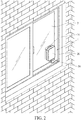
- the indoor network sharing device 20 is installed at a predetermined position indoor, for example, installed on a wall, a desk, or a window inside a building. As shown in FIG. 2 and FIG. 3 , in this embodiment, the indoor network sharing device 20 is installed on an inner surface of a window 2.
- the indoor network sharing device 20 may be provided with a nano tape 24.
- the nano tape 24 may be, but not limited to, a gecko tape.
- the nano tape 24 is provided with a bonding surface 241 and an absorption surface 242 opposite to each other.
- the bonding surface 241 is fixedly disposed on (for example, fixedly adhered to) a surface of the indoor network sharing device 20.
- the absorption surface 242 of the nano tape 24 may be provided with a nano structure, for example, be covered with nano whiskers or nano fibers, to enable the indoor network sharing device 20 to cling to the inner surface of the window 2 through the absorption surface 242 of the nano tape 24, so that a Van der Waals force is generated between the absorption surface 242 and the inner surface of the window 2, to achieve an absorption fixing effect.
- the indoor network sharing device 20 can be easily and rapidly installed at the predetermined position by means of absorption fixing of the nano tape 24, and when the indoor network sharing device 20 needs to be disassembled or reinstalled at another position, the indoor network sharing device 20 can be easily separated from the window without leaving any traces merely by applying a force to get the indoor network sharing device 20 away from the predetermined position, thereby achieving more convenient use without extra construction.
- the indoor network sharing device 20 may alternatively be installed at the predetermined position indoor through other methods (for example, methods such as locking, adhering, or magnetic absorbing).
- the indoor network sharing device 20 is installed on a fixing member 40.
- the fixing member 40 is provided with a stop portion 41.
- the indoor network sharing device 20 abuts against the stop portion 41 to be positioned.
- the fixing member 40 includes a back plate 42.
- the back plate 42 is provided with a fixing surface 421 and a mounting surface 422 opposite to each other.
- the fixing surface 421 is configured to be fixed to the predetermined position indoor.
- the stop portion 41 includes two side plates 411 and a plurality of stop plates 413.
- the two side plates 411 extend from the mounting surface 422 and are arranged at an interval, one end of each side plate 411 is provided with a bent section 412, and the plurality of stop plates 413 extends inward from an edge that is away from the back plate 42 and that is of each side plate 411, so that the indoor network sharing device 20 can be inserted between the two side plates 411, to abut between the back plate 42, the two side plates 411, and the stop plate 413 to be positioned.
- the indoor network sharing device 20 needs to be disassembled or reinstalled at another position, the indoor network sharing device 20 can be extracted out of the fixing member 40 by applying a force.
- the fixing member 40 can be installed at any position indoor.
- the fixing surface 421 of the back plate 42 of the fixing member 40 may also be provided with at least one nano tape 43 (a plurality of nano tapes 43 is provided herein, but the instant disclosure is not limited thereto).
- the structure of the nano tape 43 may be similar to that of the nano tape 24, and details are not described herein.
- the fixing member 40 may be fixed to any position indoor through absorption of the nano tape 43, for the indoor network sharing device 20 to be installed on, and the fixing member 40 can be altered to be absorbed to any position anytime.
- the indoor network sharing device 20 may alternatively be directly placed on a desktop or ground without being fixed by a mechanism.
- the outdoor wireless transceiver device 10 is installed at a predetermined position outdoor, for example, installed on an outer wall or outside a window of a building, and is configured to wirelessly receive an external network signal.
- the outdoor wireless transceiver device 10 is installed on an outer surface of the window 2.
- a surface of the outdoor wireless transceiver device 10 may be provided with a nano tape 13.
- the structure of the nano tape 13 may be similar to that of the nano tape 24 of the indoor network sharing device 20, and details are not described herein, so that the outdoor wireless transceiver device 10 can be fixed to the outer surface of the window 2 through absorption of the nano tape 13, achieving convenience such as rapid installation without construction.
- the outdoor wireless transceiver device 10 may similarly be installed at the predetermined position outdoor through other methods (for example, methods such as locking, adhering, or magnetic absorbing). As shown in FIG. 6 , the outdoor wireless transceiver device 10 may be installed on a fixing member 50.
- the structure of the fixing member 50 may be similar to that of the fixing member 40.
- the fixing member 50 may be installed at a predetermined position outdoor, so that the outdoor wireless transceiver device 10 may abut against the fixing member 50 to be positioned.
- the high-frequency network transceiver module 11 of the outdoor wireless transceiver device 10 is configured to receive an external high-frequency network signal H.
- the high-frequency network signal H is a high-frequency (for example, 1 GHz to 300 GHz) network signal.
- the high-frequency network transceiver module 11 may be a 5G transceiver module.
- the high-frequency network transceiver module 11 may be provided with a 5G transceiver antenna, to wirelessly receive a 5G network signal, where the 5G network signal has a frequency ranging from 1 GHz to 100 GHz, and is capable of supporting a data transmission rate above 1 Gbps.
- the high-frequency network transceiver module 11 may alternatively be a high-frequency Wi-Fi transceiver module.
- the high-frequency network transceiver module 11 may be a 802.11ax or 802.11ad transceiver module and be provided with a 802.11ax or 802.11ad transceiver antenna, to wirelessly receive a 802.11ax or 802.11ad network signal, where the 802.11ax network signal has frequencies of 2.4 GHz and 5 GHz, the 802.11ad network signal has a frequency of 60 GHz, and the 802.11ax network signal and the 802.11ad network signal are capable of supporting a data transmission rate above 1 Gbps.
- the high-speed Ethernet transmission cable 30 has a transmission rate above 1 Gbps, to support a data transmission rate of the high-frequency network signal H.
- two ends of the high-speed Ethernet transmission cable 30 are respectively connected to a first RJ45 connector 32 and a second RJ45 connector 33.
- the high-speed Ethernet transmission cable 30 may be a Category 5 enhanced (Cat 5e) network cable, to support a transmission rate above 1 Gbps.
- the high-speed Ethernet transmission cable 30 may alternatively be a Category 6A (Cat 6A) network cable, to support a transmission rate of maximally up to 10 Gbps.
- the high-speed Ethernet transmission cable 30 may also be a cable supporting a transmission rate above 1 Gbps.
- the high-speed Ethernet transmission cable 30 is connected between the first RJ45 connector 32 and the second RJ45 connector 33, the first RJ45 connector 32 is connected to the first Ethernet port 12 of the outdoor wireless transceiver device 10, and the second RJ45 connector is connected to the second Ethernet port 22 of the indoor network sharing device 20.
- the high-frequency network transceiver module 11 of the outdoor wireless transceiver device 10 can, after receiving the high-frequency network signal H, transmit the high-frequency network signal H from the first Ethernet port 12 to the indoor network sharing device 20 through the high-speed Ethernet transmission cable 30 at a transmission rate above 1 Gbps, thereby achieving a high transmission efficiency with respect to the high-frequency network signal H (for example, a 5G signal, or a 802.11ax or 802.11ad signal).
- the high-speed Ethernet transmission cable 30 is provided with at least one flat cable segment 311.
- the flat cable segment 311 is a flat cable with a thickness less than 4 mm. In some embodiments, the thickness of the flat cable segment 311 may be in a range of 1 mm to 4 mm.
- the flat cable segment 311 may be a flexible cable, for example, a flexible flat cable (FFC) or a flexible printed circuit (FPC), and the thickness of the flat cable segment 311 composed thereby is less than 1 mm.
- the entire cable of the high-speed Ethernet transmission cable 30 is the flat cable segment 311, but the instant disclosure is not limited thereto. In other embodiments, alternatively, only a part of the high-speed Ethernet transmission cable 30 may be the flat cable segment 311.
- the high-speed Ethernet transmission cable 30 is provided with the flat cable segment 311, so that the high-speed Ethernet transmission cable 30 can directly pass through a door or window to connect the outdoor wireless transceiver device 10 and the indoor network sharing device 20 and the door or window can be opened or closed normally. Therefore, extra construction (for example, breaking the door or window, or drilling a wall) is not needed, thereby reducing the costs and maintaining the esthetic appearance of the indoor decorations.
- extra construction for example, breaking the door or window, or drilling a wall
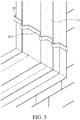
- the second RJ45 connector 33 at one end of the high-speed Ethernet transmission cable 30 may be connected to the second Ethernet port 22 of the indoor network sharing device 20, the first RJ45 connector 32 at the other end of the high-speed Ethernet transmission cable 30 may directly pass through the window 2 to be connected to the first Ethernet port 12 of the outdoor wireless transceiver device 10, and the flat cable segment 311 may be configured according to a shape of a window frame 3 of the window 2 (as shown in FIG. 5 ).
- the flat cable segment 311 is thin and therefore a sealing function can still be achieved after window 2 is closed and the original function of the window 2 is not affected.
- the indoor network sharing device 20 may be a DSL modem, a gateway, or a router.
- the processing module 21 may, after receiving the high-frequency network signal H through the second Ethernet port 22, set up a wireless local area network (Wireless LAN) or/and a wired local area network (Wired LAN), to enable a communications device (for example, a notebook computer, a smartphone, or a tablet computer) within a specific range to be connected to the indoor network sharing device 20 in a wired or wireless manner, so as to be connected to the Internet.
- the processing module 21 may be a Central Processing Unit (CPU), a Micro Control Unit (MCU), or a Micro Processing Unit (MPU).
- the outdoor wireless transceiver device 10 and the indoor network sharing device 20 may be arranged adjacent to each other, to reduce a cable material used by the high-speed Ethernet transmission cable 30 so as to reduce costs and further reduce signal attenuation.
- the outdoor wireless transceiver device 10 and the indoor network sharing device 20 are installed on inner and outer surfaces of a same position of the window 2 to be adjacent to each other.
- the outdoor wireless transceiver device 10 and the indoor network sharing device 20 may alternatively be respectively installed on different objects, but the instant disclosure is not limited thereto.
- the indoor network sharing device 20 may be connected to a power supply.
- the power supply may be a battery disposed inside the indoor network sharing device 20, to generate a power signal to provide power needed by the indoor network sharing device 20.
- the processing module 21 may further transmit the power signal to the outdoor wireless transceiver device 10 through the high-speed Ethernet transmission cable 30, so as to simultaneously provide power needed by the outdoor wireless transceiver device 10. In this way, the outdoor wireless transceiver device 10 neither needs to be provided with a battery nor be connected to the mains through a power supply lead, thereby achieving advantages such as reduced costs and easy installation. As shown in FIG.
- the power supply may alternatively be an external battery, the mains, or another power supply device, and the indoor network sharing device 20 may be connected to the power supply through a power supply lead 23, to receive a power signal and transmit the power signal to the outdoor wireless transceiver device 10 through the high-speed Ethernet transmission cable 30.
Landscapes
- Engineering & Computer Science (AREA)
- Computer Networks & Wireless Communication (AREA)
- Signal Processing (AREA)
- Automation & Control Theory (AREA)
- Multimedia (AREA)
- Computing Systems (AREA)
- Mobile Radio Communication Systems (AREA)
Applications Claiming Priority (1)
| Application Number | Priority Date | Filing Date | Title |
|---|---|---|---|
| TW107141968A TWI761634B (zh) | 2018-11-23 | 2018-11-23 | 網路分享系統 |
Publications (2)
| Publication Number | Publication Date |
|---|---|
| EP3657735A1 true EP3657735A1 (fr) | 2020-05-27 |
| EP3657735B1 EP3657735B1 (fr) | 2021-11-17 |
Family
ID=67658363
Family Applications (1)
| Application Number | Title | Priority Date | Filing Date |
|---|---|---|---|
| EP19189336.1A Active EP3657735B1 (fr) | 2018-11-23 | 2019-07-31 | Système de partage de réseau |
Country Status (3)
| Country | Link |
|---|---|
| US (1) | US10971872B2 (fr) |
| EP (1) | EP3657735B1 (fr) |
| TW (1) | TWI761634B (fr) |
Cited By (1)
| Publication number | Priority date | Publication date | Assignee | Title |
|---|---|---|---|---|
| FR3107797A1 (fr) * | 2020-03-02 | 2021-09-03 | Laurent Fournier | Système nomade de transmission de données à ultra-haut débit |
Families Citing this family (4)
| Publication number | Priority date | Publication date | Assignee | Title |
|---|---|---|---|---|
| US11716558B2 (en) | 2018-04-16 | 2023-08-01 | Charter Communications Operating, Llc | Apparatus and methods for integrated high-capacity data and wireless network services |
| US11570015B2 (en) * | 2020-04-22 | 2023-01-31 | Charter Communications Operating, Llc | Premises apparatus and methods for aggregated high-capacity data services |
| US11172544B1 (en) * | 2020-07-24 | 2021-11-09 | Inseego Corp. | Systems and methods for transferring wireless power and data for a 5G wireless access point |
| US12177791B2 (en) * | 2021-11-22 | 2024-12-24 | T-Mobile Innovations Llc | Fixed wireless access for multi-unit structures |
Citations (4)
| Publication number | Priority date | Publication date | Assignee | Title |
|---|---|---|---|---|
| EP2770672A2 (fr) * | 2013-02-20 | 2014-08-27 | Arcadyan Technology Corp. | Système de communication sans fil et procédé de gestion |
| US20160197434A1 (en) * | 2015-01-05 | 2016-07-07 | Echostar Technologies L.L.C. | Flat ethernet cables and associated systems, devices, and methods |
| EP3132593A1 (fr) * | 2014-04-18 | 2017-02-22 | Cisco Technology, Inc. | Commande de dispositifs à alimentation intelligente |
| WO2018175615A1 (fr) * | 2017-03-22 | 2018-09-27 | Nxgen Partner Ip, Llc | Ré-génération et ré-émission d'ondes millimétriques destinées à pénétrer dans un bâtiment |
Family Cites Families (11)
| Publication number | Priority date | Publication date | Assignee | Title |
|---|---|---|---|---|
| US6778099B1 (en) * | 1998-05-01 | 2004-08-17 | Elster Electricity, Llc | Wireless area network communications module for utility meters |
| US6373348B1 (en) * | 2000-08-11 | 2002-04-16 | Tektronix, Inc. | High speed differential attenuator using a low temperature co-fired ceramic substrate |
| TWI320025B (en) * | 2005-04-15 | 2010-02-01 | Glue band having a nanometer-level carbon material and method for making the same | |
| JPWO2009054476A1 (ja) | 2007-10-24 | 2011-03-10 | マスプロ電工株式会社 | フラットケーブル装置 |
| CN201315708Y (zh) * | 2008-11-11 | 2009-09-23 | 深圳市乐得威科技有限公司 | 手持、壁挂两用遥控器 |
| WO2012142586A1 (fr) * | 2011-04-15 | 2012-10-18 | Power Tagging Technologies, Inc. | Système et procédé permettant une optimisation unique et multizones de la prestation et de l'utilisation de services utilitaires |
| CA2911094C (fr) | 2013-04-30 | 2024-05-28 | Manolo Fabio Rivera | Prise murale polyvalente avec transmission de donnees sans fil |
| CN103619080B (zh) * | 2013-12-06 | 2016-06-29 | 德明通讯(上海)有限责任公司 | 一种低成本单网口lte路由设备及控制方法 |
| US9727798B2 (en) * | 2014-07-18 | 2017-08-08 | Acrovirt, LLC | Generating and using a predictive virtual personification |
| CN105789951A (zh) * | 2016-04-30 | 2016-07-20 | 佘培嘉 | 一种针对rj45改良网络接口的新方法 |
| CN207977590U (zh) * | 2018-02-28 | 2018-10-16 | 重庆恒芯天际科技有限公司 | 一种具有供电及数据传输功能的数据电源线 |
-
2018
- 2018-11-23 TW TW107141968A patent/TWI761634B/zh active
-
2019
- 2019-06-28 US US16/456,126 patent/US10971872B2/en active Active
- 2019-07-31 EP EP19189336.1A patent/EP3657735B1/fr active Active
Patent Citations (4)
| Publication number | Priority date | Publication date | Assignee | Title |
|---|---|---|---|---|
| EP2770672A2 (fr) * | 2013-02-20 | 2014-08-27 | Arcadyan Technology Corp. | Système de communication sans fil et procédé de gestion |
| EP3132593A1 (fr) * | 2014-04-18 | 2017-02-22 | Cisco Technology, Inc. | Commande de dispositifs à alimentation intelligente |
| US20160197434A1 (en) * | 2015-01-05 | 2016-07-07 | Echostar Technologies L.L.C. | Flat ethernet cables and associated systems, devices, and methods |
| WO2018175615A1 (fr) * | 2017-03-22 | 2018-09-27 | Nxgen Partner Ip, Llc | Ré-génération et ré-émission d'ondes millimétriques destinées à pénétrer dans un bâtiment |
Cited By (2)
| Publication number | Priority date | Publication date | Assignee | Title |
|---|---|---|---|---|
| FR3107797A1 (fr) * | 2020-03-02 | 2021-09-03 | Laurent Fournier | Système nomade de transmission de données à ultra-haut débit |
| WO2021175777A1 (fr) * | 2020-03-02 | 2021-09-10 | Laurent Fournier | Système nomade de transmission de données à ultra-haut débit |
Also Published As
| Publication number | Publication date |
|---|---|
| US10971872B2 (en) | 2021-04-06 |
| TW202021402A (zh) | 2020-06-01 |
| US20200169049A1 (en) | 2020-05-28 |
| TWI761634B (zh) | 2022-04-21 |
| EP3657735B1 (fr) | 2021-11-17 |
Similar Documents
| Publication | Publication Date | Title |
|---|---|---|
| US10971872B2 (en) | Network sharing system | |
| US10659156B2 (en) | Apparatus and method for facilitating communication between a telecommunications network and a user device within a building | |
| US20160302002A1 (en) | Band-limited Beamforming Microphone Array | |
| US7065350B2 (en) | Apparatus and method for communicating a wireless data signal in a building | |
| US20160197434A1 (en) | Flat ethernet cables and associated systems, devices, and methods | |
| CN201039376Y (zh) | 一种便携式无线可视门铃 | |
| CN101242721A (zh) | 可携式电子装置 | |
| KR20090071841A (ko) | 세대단자함 | |
| WO2023083122A1 (fr) | Poignée de module d'antenne, ordinateur enfichable ouvert et dispositif électronique | |
| CN209374798U (zh) | 一种网线卡扣 | |
| CN210725185U (zh) | 一种基于定向音频的柜台对讲系统 | |
| KR101101414B1 (ko) | 무선 모뎀 장치 | |
| CN111341005B (zh) | 速通门控制装置及系统 | |
| CN205510280U (zh) | 一种掀盖式电子猫眼室内主机 | |
| CN220421827U (zh) | 一种远程控制的智能广播装置 | |
| CN215761211U (zh) | 一种便于安装的报警平开窗 | |
| CN217206028U (zh) | 双面铝框镜门 | |
| CN205318778U (zh) | 一种方便前维护的led显示屏单元 | |
| CN218122894U (zh) | 一种利于拆卸检修的镜面广告机 | |
| CN211718800U (zh) | 扩展坞 | |
| CN216122460U (zh) | 一种带双射频的全双工loraWAN智能型工业网关 | |
| CN209488742U (zh) | 对讲室内机 | |
| US20060168758A1 (en) | Hinge structure | |
| CN204968026U (zh) | 可插拔式电子猫眼可视门铃 | |
| CN211349442U (zh) | 一种基于移动终端的楼宇防控系统 |
Legal Events
| Date | Code | Title | Description |
|---|---|---|---|
| PUAI | Public reference made under article 153(3) epc to a published international application that has entered the european phase |
Free format text: ORIGINAL CODE: 0009012 |
|
| STAA | Information on the status of an ep patent application or granted ep patent |
Free format text: STATUS: THE APPLICATION HAS BEEN PUBLISHED |
|
| AK | Designated contracting states |
Kind code of ref document: A1 Designated state(s): AL AT BE BG CH CY CZ DE DK EE ES FI FR GB GR HR HU IE IS IT LI LT LU LV MC MK MT NL NO PL PT RO RS SE SI SK SM TR |
|
| AX | Request for extension of the european patent |
Extension state: BA ME |
|
| STAA | Information on the status of an ep patent application or granted ep patent |
Free format text: STATUS: REQUEST FOR EXAMINATION WAS MADE |
|
| 17P | Request for examination filed |
Effective date: 20200629 |
|
| RBV | Designated contracting states (corrected) |
Designated state(s): AL AT BE BG CH CY CZ DE DK EE ES FI FR GB GR HR HU IE IS IT LI LT LU LV MC MK MT NL NO PL PT RO RS SE SI SK SM TR |
|
| STAA | Information on the status of an ep patent application or granted ep patent |
Free format text: STATUS: EXAMINATION IS IN PROGRESS |
|
| 17Q | First examination report despatched |
Effective date: 20201112 |
|
| REG | Reference to a national code |
Ref country code: DE Ref legal event code: R079 Ref document number: 602019009316 Country of ref document: DE Free format text: PREVIOUS MAIN CLASS: H04L0012280000 Ipc: H04W0084120000 |
|
| GRAP | Despatch of communication of intention to grant a patent |
Free format text: ORIGINAL CODE: EPIDOSNIGR1 |
|
| STAA | Information on the status of an ep patent application or granted ep patent |
Free format text: STATUS: GRANT OF PATENT IS INTENDED |
|
| RIC1 | Information provided on ipc code assigned before grant |
Ipc: H04W 84/12 20090101AFI20210618BHEP Ipc: H04W 88/08 20090101ALI20210618BHEP Ipc: H04L 12/28 20060101ALI20210618BHEP |
|
| INTG | Intention to grant announced |
Effective date: 20210707 |
|
| GRAS | Grant fee paid |
Free format text: ORIGINAL CODE: EPIDOSNIGR3 |
|
| GRAA | (expected) grant |
Free format text: ORIGINAL CODE: 0009210 |
|
| STAA | Information on the status of an ep patent application or granted ep patent |
Free format text: STATUS: THE PATENT HAS BEEN GRANTED |
|
| AK | Designated contracting states |
Kind code of ref document: B1 Designated state(s): AL AT BE BG CH CY CZ DE DK EE ES FI FR GB GR HR HU IE IS IT LI LT LU LV MC MK MT NL NO PL PT RO RS SE SI SK SM TR |
|
| REG | Reference to a national code |
Ref country code: GB Ref legal event code: FG4D |
|
| RAP4 | Party data changed (patent owner data changed or rights of a patent transferred) |
Owner name: ASKEY COMPUTER CORP. |
|
| REG | Reference to a national code |
Ref country code: IE Ref legal event code: FG4D |
|
| REG | Reference to a national code |
Ref country code: DE Ref legal event code: R096 Ref document number: 602019009316 Country of ref document: DE |
|
| REG | Reference to a national code |
Ref country code: AT Ref legal event code: REF Ref document number: 1449093 Country of ref document: AT Kind code of ref document: T Effective date: 20211215 |
|
| REG | Reference to a national code |
Ref country code: LT Ref legal event code: MG9D |
|
| REG | Reference to a national code |
Ref country code: NL Ref legal event code: MP Effective date: 20211117 |
|
| REG | Reference to a national code |
Ref country code: AT Ref legal event code: MK05 Ref document number: 1449093 Country of ref document: AT Kind code of ref document: T Effective date: 20211117 |
|
| PG25 | Lapsed in a contracting state [announced via postgrant information from national office to epo] |
Ref country code: RS Free format text: LAPSE BECAUSE OF FAILURE TO SUBMIT A TRANSLATION OF THE DESCRIPTION OR TO PAY THE FEE WITHIN THE PRESCRIBED TIME-LIMIT Effective date: 20211117 Ref country code: LT Free format text: LAPSE BECAUSE OF FAILURE TO SUBMIT A TRANSLATION OF THE DESCRIPTION OR TO PAY THE FEE WITHIN THE PRESCRIBED TIME-LIMIT Effective date: 20211117 Ref country code: FI Free format text: LAPSE BECAUSE OF FAILURE TO SUBMIT A TRANSLATION OF THE DESCRIPTION OR TO PAY THE FEE WITHIN THE PRESCRIBED TIME-LIMIT Effective date: 20211117 Ref country code: BG Free format text: LAPSE BECAUSE OF FAILURE TO SUBMIT A TRANSLATION OF THE DESCRIPTION OR TO PAY THE FEE WITHIN THE PRESCRIBED TIME-LIMIT Effective date: 20220217 Ref country code: AT Free format text: LAPSE BECAUSE OF FAILURE TO SUBMIT A TRANSLATION OF THE DESCRIPTION OR TO PAY THE FEE WITHIN THE PRESCRIBED TIME-LIMIT Effective date: 20211117 |
|
| PG25 | Lapsed in a contracting state [announced via postgrant information from national office to epo] |
Ref country code: IS Free format text: LAPSE BECAUSE OF FAILURE TO SUBMIT A TRANSLATION OF THE DESCRIPTION OR TO PAY THE FEE WITHIN THE PRESCRIBED TIME-LIMIT Effective date: 20220317 Ref country code: SE Free format text: LAPSE BECAUSE OF FAILURE TO SUBMIT A TRANSLATION OF THE DESCRIPTION OR TO PAY THE FEE WITHIN THE PRESCRIBED TIME-LIMIT Effective date: 20211117 Ref country code: PT Free format text: LAPSE BECAUSE OF FAILURE TO SUBMIT A TRANSLATION OF THE DESCRIPTION OR TO PAY THE FEE WITHIN THE PRESCRIBED TIME-LIMIT Effective date: 20220317 Ref country code: PL Free format text: LAPSE BECAUSE OF FAILURE TO SUBMIT A TRANSLATION OF THE DESCRIPTION OR TO PAY THE FEE WITHIN THE PRESCRIBED TIME-LIMIT Effective date: 20211117 Ref country code: NO Free format text: LAPSE BECAUSE OF FAILURE TO SUBMIT A TRANSLATION OF THE DESCRIPTION OR TO PAY THE FEE WITHIN THE PRESCRIBED TIME-LIMIT Effective date: 20220217 Ref country code: NL Free format text: LAPSE BECAUSE OF FAILURE TO SUBMIT A TRANSLATION OF THE DESCRIPTION OR TO PAY THE FEE WITHIN THE PRESCRIBED TIME-LIMIT Effective date: 20211117 Ref country code: LV Free format text: LAPSE BECAUSE OF FAILURE TO SUBMIT A TRANSLATION OF THE DESCRIPTION OR TO PAY THE FEE WITHIN THE PRESCRIBED TIME-LIMIT Effective date: 20211117 Ref country code: HR Free format text: LAPSE BECAUSE OF FAILURE TO SUBMIT A TRANSLATION OF THE DESCRIPTION OR TO PAY THE FEE WITHIN THE PRESCRIBED TIME-LIMIT Effective date: 20211117 Ref country code: GR Free format text: LAPSE BECAUSE OF FAILURE TO SUBMIT A TRANSLATION OF THE DESCRIPTION OR TO PAY THE FEE WITHIN THE PRESCRIBED TIME-LIMIT Effective date: 20220218 Ref country code: ES Free format text: LAPSE BECAUSE OF FAILURE TO SUBMIT A TRANSLATION OF THE DESCRIPTION OR TO PAY THE FEE WITHIN THE PRESCRIBED TIME-LIMIT Effective date: 20211117 |
|
| PG25 | Lapsed in a contracting state [announced via postgrant information from national office to epo] |
Ref country code: SM Free format text: LAPSE BECAUSE OF FAILURE TO SUBMIT A TRANSLATION OF THE DESCRIPTION OR TO PAY THE FEE WITHIN THE PRESCRIBED TIME-LIMIT Effective date: 20211117 Ref country code: SK Free format text: LAPSE BECAUSE OF FAILURE TO SUBMIT A TRANSLATION OF THE DESCRIPTION OR TO PAY THE FEE WITHIN THE PRESCRIBED TIME-LIMIT Effective date: 20211117 Ref country code: RO Free format text: LAPSE BECAUSE OF FAILURE TO SUBMIT A TRANSLATION OF THE DESCRIPTION OR TO PAY THE FEE WITHIN THE PRESCRIBED TIME-LIMIT Effective date: 20211117 Ref country code: DK Free format text: LAPSE BECAUSE OF FAILURE TO SUBMIT A TRANSLATION OF THE DESCRIPTION OR TO PAY THE FEE WITHIN THE PRESCRIBED TIME-LIMIT Effective date: 20211117 Ref country code: CZ Free format text: LAPSE BECAUSE OF FAILURE TO SUBMIT A TRANSLATION OF THE DESCRIPTION OR TO PAY THE FEE WITHIN THE PRESCRIBED TIME-LIMIT Effective date: 20211117 |
|
| REG | Reference to a national code |
Ref country code: DE Ref legal event code: R097 Ref document number: 602019009316 Country of ref document: DE |
|
| PLBE | No opposition filed within time limit |
Free format text: ORIGINAL CODE: 0009261 |
|
| STAA | Information on the status of an ep patent application or granted ep patent |
Free format text: STATUS: NO OPPOSITION FILED WITHIN TIME LIMIT |
|
| 26N | No opposition filed |
Effective date: 20220818 |
|
| PG25 | Lapsed in a contracting state [announced via postgrant information from national office to epo] |
Ref country code: AL Free format text: LAPSE BECAUSE OF FAILURE TO SUBMIT A TRANSLATION OF THE DESCRIPTION OR TO PAY THE FEE WITHIN THE PRESCRIBED TIME-LIMIT Effective date: 20211117 |
|
| PG25 | Lapsed in a contracting state [announced via postgrant information from national office to epo] |
Ref country code: SI Free format text: LAPSE BECAUSE OF FAILURE TO SUBMIT A TRANSLATION OF THE DESCRIPTION OR TO PAY THE FEE WITHIN THE PRESCRIBED TIME-LIMIT Effective date: 20211117 |
|
| PG25 | Lapsed in a contracting state [announced via postgrant information from national office to epo] |
Ref country code: MC Free format text: LAPSE BECAUSE OF FAILURE TO SUBMIT A TRANSLATION OF THE DESCRIPTION OR TO PAY THE FEE WITHIN THE PRESCRIBED TIME-LIMIT Effective date: 20211117 |
|
| REG | Reference to a national code |
Ref country code: CH Ref legal event code: PL |
|
| REG | Reference to a national code |
Ref country code: BE Ref legal event code: MM Effective date: 20220731 |
|
| PG25 | Lapsed in a contracting state [announced via postgrant information from national office to epo] |
Ref country code: LU Free format text: LAPSE BECAUSE OF NON-PAYMENT OF DUE FEES Effective date: 20220731 Ref country code: LI Free format text: LAPSE BECAUSE OF NON-PAYMENT OF DUE FEES Effective date: 20220731 Ref country code: CH Free format text: LAPSE BECAUSE OF NON-PAYMENT OF DUE FEES Effective date: 20220731 |
|
| PG25 | Lapsed in a contracting state [announced via postgrant information from national office to epo] |
Ref country code: IT Free format text: LAPSE BECAUSE OF FAILURE TO SUBMIT A TRANSLATION OF THE DESCRIPTION OR TO PAY THE FEE WITHIN THE PRESCRIBED TIME-LIMIT Effective date: 20211117 Ref country code: BE Free format text: LAPSE BECAUSE OF NON-PAYMENT OF DUE FEES Effective date: 20220731 |
|
| PG25 | Lapsed in a contracting state [announced via postgrant information from national office to epo] |
Ref country code: IE Free format text: LAPSE BECAUSE OF NON-PAYMENT OF DUE FEES Effective date: 20220731 |
|
| PG25 | Lapsed in a contracting state [announced via postgrant information from national office to epo] |
Ref country code: MK Free format text: LAPSE BECAUSE OF FAILURE TO SUBMIT A TRANSLATION OF THE DESCRIPTION OR TO PAY THE FEE WITHIN THE PRESCRIBED TIME-LIMIT Effective date: 20211117 Ref country code: EE Free format text: LAPSE BECAUSE OF FAILURE TO SUBMIT A TRANSLATION OF THE DESCRIPTION OR TO PAY THE FEE WITHIN THE PRESCRIBED TIME-LIMIT Effective date: 20211117 Ref country code: CY Free format text: LAPSE BECAUSE OF FAILURE TO SUBMIT A TRANSLATION OF THE DESCRIPTION OR TO PAY THE FEE WITHIN THE PRESCRIBED TIME-LIMIT Effective date: 20211117 |
|
| PG25 | Lapsed in a contracting state [announced via postgrant information from national office to epo] |
Ref country code: HU Free format text: LAPSE BECAUSE OF FAILURE TO SUBMIT A TRANSLATION OF THE DESCRIPTION OR TO PAY THE FEE WITHIN THE PRESCRIBED TIME-LIMIT; INVALID AB INITIO Effective date: 20190731 |
|
| PG25 | Lapsed in a contracting state [announced via postgrant information from national office to epo] |
Ref country code: MT Free format text: LAPSE BECAUSE OF FAILURE TO SUBMIT A TRANSLATION OF THE DESCRIPTION OR TO PAY THE FEE WITHIN THE PRESCRIBED TIME-LIMIT Effective date: 20211117 |
|
| PGFP | Annual fee paid to national office [announced via postgrant information from national office to epo] |
Ref country code: DE Payment date: 20250723 Year of fee payment: 7 |
|
| PGFP | Annual fee paid to national office [announced via postgrant information from national office to epo] |
Ref country code: GB Payment date: 20250822 Year of fee payment: 7 |
|
| PGFP | Annual fee paid to national office [announced via postgrant information from national office to epo] |
Ref country code: FR Payment date: 20250729 Year of fee payment: 7 |
|
| PG25 | Lapsed in a contracting state [announced via postgrant information from national office to epo] |
Ref country code: TR Free format text: LAPSE BECAUSE OF FAILURE TO SUBMIT A TRANSLATION OF THE DESCRIPTION OR TO PAY THE FEE WITHIN THE PRESCRIBED TIME-LIMIT Effective date: 20211117 |