EP3657876A1 - Procédé de transmission et dispositif associé - Google Patents
Procédé de transmission et dispositif associé Download PDFInfo
- Publication number
- EP3657876A1 EP3657876A1 EP18834967.4A EP18834967A EP3657876A1 EP 3657876 A1 EP3657876 A1 EP 3657876A1 EP 18834967 A EP18834967 A EP 18834967A EP 3657876 A1 EP3657876 A1 EP 3657876A1
- Authority
- EP
- European Patent Office
- Prior art keywords
- frequency domain
- transmission frequency
- terminal device
- candidate transmission
- domain resources
- Prior art date
- Legal status (The legal status is an assumption and is not a legal conclusion. Google has not performed a legal analysis and makes no representation as to the accuracy of the status listed.)
- Pending
Links
Images




Classifications
-
- H—ELECTRICITY
- H04—ELECTRIC COMMUNICATION TECHNIQUE
- H04L—TRANSMISSION OF DIGITAL INFORMATION, e.g. TELEGRAPHIC COMMUNICATION
- H04L5/00—Arrangements affording multiple use of the transmission path
- H04L5/003—Arrangements for allocating sub-channels of the transmission path
- H04L5/0048—Allocation of pilot signals, i.e. of signals known to the receiver
-
- H—ELECTRICITY
- H04—ELECTRIC COMMUNICATION TECHNIQUE
- H04W—WIRELESS COMMUNICATION NETWORKS
- H04W72/00—Local resource management
- H04W72/02—Selection of wireless resources by user or terminal
-
- H—ELECTRICITY
- H04—ELECTRIC COMMUNICATION TECHNIQUE
- H04L—TRANSMISSION OF DIGITAL INFORMATION, e.g. TELEGRAPHIC COMMUNICATION
- H04L5/00—Arrangements affording multiple use of the transmission path
- H04L5/0001—Arrangements for dividing the transmission path
- H04L5/0003—Two-dimensional division
- H04L5/0005—Time-frequency
- H04L5/0007—Time-frequency the frequencies being orthogonal, e.g. OFDM(A) or DMT
- H04L5/001—Time-frequency the frequencies being orthogonal, e.g. OFDM(A) or DMT the frequencies being arranged in component carriers
-
- H—ELECTRICITY
- H04—ELECTRIC COMMUNICATION TECHNIQUE
- H04L—TRANSMISSION OF DIGITAL INFORMATION, e.g. TELEGRAPHIC COMMUNICATION
- H04L5/00—Arrangements affording multiple use of the transmission path
- H04L5/003—Arrangements for allocating sub-channels of the transmission path
- H04L5/0053—Allocation of signalling, i.e. of overhead other than pilot signals
-
- H—ELECTRICITY
- H04—ELECTRIC COMMUNICATION TECHNIQUE
- H04L—TRANSMISSION OF DIGITAL INFORMATION, e.g. TELEGRAPHIC COMMUNICATION
- H04L5/00—Arrangements affording multiple use of the transmission path
- H04L5/003—Arrangements for allocating sub-channels of the transmission path
- H04L5/0053—Allocation of signalling, i.e. of overhead other than pilot signals
- H04L5/0055—Physical resource allocation for ACK/NACK
-
- H—ELECTRICITY
- H04—ELECTRIC COMMUNICATION TECHNIQUE
- H04W—WIRELESS COMMUNICATION NETWORKS
- H04W72/00—Local resource management
- H04W72/04—Wireless resource allocation
- H04W72/044—Wireless resource allocation based on the type of the allocated resource
- H04W72/0453—Resources in frequency domain, e.g. a carrier in FDMA
-
- H—ELECTRICITY
- H04—ELECTRIC COMMUNICATION TECHNIQUE
- H04W—WIRELESS COMMUNICATION NETWORKS
- H04W72/00—Local resource management
- H04W72/20—Control channels or signalling for resource management
- H04W72/23—Control channels or signalling for resource management in the downlink direction of a wireless link, i.e. towards a terminal
-
- H—ELECTRICITY
- H04—ELECTRIC COMMUNICATION TECHNIQUE
- H04W—WIRELESS COMMUNICATION NETWORKS
- H04W74/00—Wireless channel access
- H04W74/002—Transmission of channel access control information
- H04W74/006—Transmission of channel access control information in the downlink, i.e. towards the terminal
-
- H—ELECTRICITY
- H04—ELECTRIC COMMUNICATION TECHNIQUE
- H04W—WIRELESS COMMUNICATION NETWORKS
- H04W74/00—Wireless channel access
- H04W74/08—Non-scheduled access, e.g. ALOHA
- H04W74/0808—Non-scheduled access, e.g. ALOHA using carrier sensing, e.g. carrier sense multiple access [CSMA]
- H04W74/0816—Non-scheduled access, e.g. ALOHA using carrier sensing, e.g. carrier sense multiple access [CSMA] with collision avoidance
-
- H—ELECTRICITY
- H04—ELECTRIC COMMUNICATION TECHNIQUE
- H04W—WIRELESS COMMUNICATION NETWORKS
- H04W72/00—Local resource management
- H04W72/20—Control channels or signalling for resource management
- H04W72/21—Control channels or signalling for resource management in the uplink direction of a wireless link, i.e. towards the network
-
- H—ELECTRICITY
- H04—ELECTRIC COMMUNICATION TECHNIQUE
- H04W—WIRELESS COMMUNICATION NETWORKS
- H04W74/00—Wireless channel access
- H04W74/08—Non-scheduled access, e.g. ALOHA
- H04W74/0808—Non-scheduled access, e.g. ALOHA using carrier sensing, e.g. carrier sense multiple access [CSMA]
-
- H—ELECTRICITY
- H04—ELECTRIC COMMUNICATION TECHNIQUE
- H04W—WIRELESS COMMUNICATION NETWORKS
- H04W88/00—Devices specially adapted for wireless communication networks, e.g. terminals, base stations or access point devices
- H04W88/02—Terminal devices
- H04W88/06—Terminal devices adapted for operation in multiple networks or having at least two operational modes, e.g. multi-mode terminals
Definitions
- This application relates to the field of communications technologies, and in particular, to a transmission method and an apparatus thereof.
- a wireless communications system of another type represented by an 802.11 system, works on the unlicensed frequency spectrum. That is, the frequency band is not dedicated to the 802.11 system, and another communications system can also use the unlicensed frequency spectrum. Therefore, for communication on the unlicensed frequency spectrum, problems of frequency spectrum contention between different systems and fairness need to be considered.
- a communications mechanism of the unlicensed frequency spectrum is greatly different from that of the licensed frequency spectrum.
- a technical problem to be resolved by embodiments of this application is to provide a transmission method and an apparatus thereof, so that uplink transmission can be implemented by using an unlicensed frequency spectrum, and transmission efficiency can be improved.
- an embodiment of this application provides a transmission method, including:
- an embodiment of this application provides a terminal device, including a unit or means (means) configured to perform each step according to the foregoing first aspect.
- an embodiment of this application provides a terminal device, including at least one processing element and at least one storage element, where the at least one storage element is configured to store a program and data, and the at least one processing element is configured to perform the method provided in the first aspect of this application.
- an embodiment of this application provides a terminal device, including at least one processing element (or chip) configured to perform the method according to the first aspect.
- an embodiment of this application provides a program.
- the program is used to perform the method according to the first aspect when executed by a processor.
- an embodiment of this application provides a program product, such as a computer-readable storage medium, including the program according to the fifth aspect.
- the terminal device performs idle state sensing on the one or more candidate transmission frequency domain resources to determine the transmission frequency domain resource used for PUCCH information transmission, where the one or more candidate transmission frequency domain resources may be unlicensed frequency domain resources, so that uplink transmission can be implemented by using an unlicensed frequency spectrum, and transmission efficiency can be improved.
- the one or more candidate transmission frequency domain resources may be presented in a form of a set. That is, one candidate transmission frequency domain resource set includes the one or more candidate transmission frequency domain resources.
- the terminal device before performing Step 1, the terminal device further performs a step of determining the one or more candidate transmission frequency domain resources.
- the terminal device can perform idle state sensing on the one or more candidate transmission frequency domain resources.
- the terminal device receives PUCCH resource configuration information from a network device.
- the PUCCH resource configuration information is used to indicate the one or more candidate transmission frequency domain resources, and the terminal device determines the one or more candidate transmission frequency domain resources based on the PUCCH resource configuration information. This is a manner of directly indicating the one or more candidate transmission frequency domain resources by the network device by using the PUCCH resource configuration information, and is simple, direct, and easy to be implemented.
- the PUCCH resource configuration information is carried in downlink control information. That is, the network device indicates the one or more candidate transmission frequency domain resources to the terminal device by using the downlink control information.
- the PUCCH resource configuration information apart from being used to indicate the one or more candidate transmission frequency domain resources, is further used to indicate location information of the candidate transmission frequency domain resources.
- the terminal device obtains a downlink transmission resource, and determines the one or more candidate transmission frequency domain resources based on the downlink transmission resource.
- the terminal device and the network device store a correspondence between the downlink transmission resource and the candidate transmission frequency domain resource set. That is, different downlink transmission resources may correspond to different candidate transmission frequency domain resource sets.
- the terminal device determines the candidate transmission frequency domain resource set, to be specific, determines the one or more candidate transmission frequency domain resources, based on the correspondence between the downlink transmission resource and the candidate transmission frequency domain resource set. This is a manner of indirectly indicating the one or more candidate transmission frequency domain resources by the network device by using the downlink transmission resource without adding extra indication overheads.
- the terminal device determines the candidate transmission frequency domain resource as a transmission frequency domain resource used for PUCCH information transmission.
- the terminal device if the terminal device senses that at least two candidate transmission frequency domain resources are in an idle state, the terminal device selects one candidate transmission frequency domain resource from the at least two candidate transmission frequency domain resources based on an identifier of the terminal device, and determines the selected candidate transmission frequency domain resource as a transmission domain resource used for PUCCH information transmission. For example, a quantity of candidate transmission frequency domain resources in an idle state is used to perform a modulo operation on the identifier of the terminal device, to select one candidate transmission frequency domain resource.
- the terminal device if the terminal device senses that at least two candidate transmission frequency domain resources are in an idle state, the terminal device randomly selects one candidate transmission frequency domain resource from the at least two candidate transmission frequency domain resources, and determines the selected candidate transmission frequency domain resource as a transmission domain resource used for PUCCH information transmission.
- the terminal device determines all candidate transmission frequency domain resources in an idle state as transmission frequency domain resources used for PUCCH information transmission. Assuming that there are two candidate transmission frequency domain resources in an idle state, the terminal device transmits the PUCCH information on the two candidate transmission frequency domain resources. In this way, the network device does not need to perform blind detection, and directly combines and receives the PUCCH information on the two candidate transmission frequency domain resources.
- FIG. 1 a schematic diagram of a network architecture according to an embodiment of this application.
- the network architecture may be a network architecture of a wireless communications system, and may include a terminal device and a network device. It should be noted that, quantities and forms of the terminal devices and network devices shown in FIG. 1 are not limitations to embodiments of this application. In an actual application, one network device may be connected to a plurality of terminal devices.
- the network device may be connected to a core network device, and the core network device is not shown in FIG. 1 .
- the network device may be a base station, and the base station may include a baseband unit (baseband unit, BBU) and a remote radio unit (remote radio unit, RRU).
- BBU baseband unit
- RRU remote radio unit
- the RRU is remotely placed in a spacious area with a high traffic volume, and the BBU is placed in a central equipment room.
- the BBU and the RRU may alternatively be placed in a same equipment room.
- the BBU and the RRU may alternatively be different components on one rack.
- the wireless communications system mentioned in embodiments of this application includes, but is not limited to: a narrow band internet of things (narrow band-internet of things, NB-IoT) system, a global system for mobile communications (global system for mobile communications, GSM), an enhanced data rate for GSM evolution (enhanced data rate for GSM evolution, EDGE) system, a wideband code division multiple access (wideband code division multiple access, WCDMA) system, a code division multiple access 2000 (code division multiple access, CDMA2000) system, a time division-synchronization code division multiple access (time division-synchronization code division multiple access, TD-SCDMA) system, a long term evolution (long term evolution, LTE) system, a fifth-generation mobile communications system, and a future mobile communications system.
- NB-IoT narrow band internet of things
- GSM global system for mobile communications
- GSM evolution enhanced data rate for GSM evolution
- EDGE enhanced data rate for GSM evolution
- WCDMA wideband code division multiple access
- a network device is an apparatus deployed in a radio access network and configured to provide a wireless communication function for user equipment.
- the network device may include a macro base station, a micro base station (also referred to as a small cell), a relay station, an access point, a TRP, and the like that are in various forms.
- a device having a function of the base station may be named differently.
- the device is referred to as an eNB or eNodeB in an LTE system, and referred to as an NB or the like in a 3rd generation (3rd Generation, 3G) system.
- 3rd Generation 3rd Generation
- the terminal device in the embodiments of this application may include various handheld devices, vehicle-mounted devices, wearable devices, or computing devices that have a wireless communication function, or other processing devices connected to a wireless modem.
- a terminal device For ease of description, in all embodiments of this application, user equipments connected to the network devices are collectively referred to as a terminal device.
- a network device transmits downlink data to a terminal device, where the data is encoded by using channel coding, and the data obtained after the channel coding is transmitted to the terminal device after being subject constellation modulation; and the terminal device transmits uplink data to the network device, where the uplink data may also be encoded by using the channel coding, and the encoded data is transmitted to the network device after being subject constellation modulation.
- Enhanced licensed-assisted access is an implementation solution of introducing the LTE system to an unlicensed frequency spectrum.
- the eLAA implements channel bonding between a primary cell and a secondary cell in a manner of carrier aggregation (carrier aggregation, CA).
- the primary cell primary cell, Pcell
- the secondary cell secondary cell, Scell
- a physical uplink control channel (physical uplink control channel, PUCCH) is only transmitted on the Pcell, to be specific, transmitted on a licensed frequency spectrum (also referred to as: licensed frequency band), and is usually configured to be on an edge of an uplink system bandwidth in terms of a frequency domain, as shown in FIG. 3 .
- PUCCH Physical uplink control channel
- One PUCCH occupies two slots (slot) in one uplink subframe (subframe), and each slot occupies 12 subcarriers, namely one resource block (resource block, RB), in a frequency domain.
- resource blocks physical resource block, PRB) of two consecutive slots of the PUCCH are respectively located on two ends of an available frequency spectrum resource.
- a plurality of UEs in a same cell may share a same RB pair to send respective PUCCHs.
- This is implemented through orthogonal code division multiplexing (orthogonal code division multiplexing, CDM): using a cyclic shift in a frequency domain or using an orthogonal sequence in a time domain.
- CDM orthogonal code division multiplexing
- a possible scenario in 5G is standalone networking on an unlicensed frequency band. That is, without using a licensed frequency band, all control and data signals are transmitted on the unlicensed frequency band.
- inter-system interference such as interference from Bluetooth or a wireless local area network (wireless local area networks, WLAN), on the unlicensed frequency spectrum. Therefore, a site that transmits data first needs to perform listen before talk (listen before talk, LBT), to be specific, needs to sense whether a channel is idle, to determine whether another site is transmitting data. If the channel is idle, the site can transmit data; otherwise, the site backs off for a period of time before trying again. Therefore, there is possibility that the PUCCH cannot be sent because the channel is not idle.
- listen before talk LBT
- a current unlicensed frequency band has a relatively large available bandwidth, such as an 80/160 MHz bandwidth
- an actual bandwidth of each transmission is flexible and changeable due to existence of LBT. Assuming that the PUCCH is transmitted only on the Pcell, if LBT of the Pcell fails, UE cannot respond to the PUCCH even if LBT of another Scell succeeds. As a result, a system latency is increased, and transmission efficiency is reduced.
- the embodiments of this application provide a transmission method and an apparatus thereof, so that uplink transmission can be implemented by using an unlicensed frequency spectrum, and transmission efficiency can be improved.
- the transmission method and the apparatus thereof provided in the embodiments of this application can be applied to a scenario of communication between a network device and a terminal device on an unlicensed frequency band in a communications system such as 5G, and specifically, can be applied to a scenario of standalone networking on an unlicensed frequency band.
- a transmission frequency domain resource included in the embodiments of this application is used for PUCCH information uplink transmission by the terminal device, and may be an active uplink bandwidth part (bandwidth part, BWP), or may be another term used to describe PUCCH uplink transmission.
- BWP bandwidth part
- the transmission frequency domain resource is introduced by using the BWP as an example.
- a BWP includes a set of consecutive PRBs, and may be one sub-band in one single wideband carrier (single wideband carrier), or may be a bandwidth of one component carrier (component carrier, CC) in carrier aggregation (carrier aggregation, CA).
- the sub-band may correspond to one or more carriers, or correspond to some subcarriers, some resource blocks, or the like on one carrier.
- a basic unit of the BWP may be 20 MHz, 40 MHz, 60 MHz, 80 MHz, or the like. This is not limited in the embodiments of this application.
- BWP configurations of terminal devices may be same or different. This is not limited in this application.
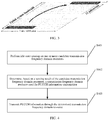
- FIG. 4 is a schematic flowchart of a transmission method according to an embodiment of this application. The method is described from a perspective of a terminal device. The method includes, but is not limited to, the following steps.
- Step S401 Perform idle state sensing on one or more candidate transmission frequency domain resources, where the candidate transmission frequency domain resource is used for PUCCH information transmission;
- the PUCCH information may be information carrying an acknowledgment (acknowledge, ACK) or negative acknowledgment (non-acknowledge, NACK), used to respond to a hybrid automatic repeat request (hybrid automatic repeat request, HARQ) sent by a network device; or may be information carrying a scheduling request (scheduling request, SR); or may be information carrying channel state information (channel state information, CSI), or may be information carrying other content.
- the PUCCH information may alternatively be information carrying several types of the ACK/NACK, the SR, the CSI, or the other content. Content carried in specific PUCCH information is not limited in this embodiment of this application. For convenience, descriptions in embodiment of this application are provided by using the PUCCH information carrying an ACK/NACK an example.
- the one or more candidate transmission frequency domain resources may be presented in a form of a set. That is, one candidate transmission frequency domain resource set includes the one or more candidate transmission frequency domain resources.
- the network device may configure a same candidate transmission frequency domain resource set or different candidate transmission frequency domain resource sets for different terminal devices. This is not limited in this embodiment of this application.
- the candidate transmission frequency domain resource set may be a transmission frequency domain resource initially configured by the network device, where, for example, the network device initially configures m (m ⁇ 1, a positive integer) BWPs for the terminal device; or may be a transmission frequency domain resource selectively activated by the network device in a period of time, for example, n selectively activated BWPs (1 ⁇ n ⁇ m); or may be one or more sub-bands in one BWP, where, for example, the network device configures an 80 MHz BWP for the terminal device, and the candidate transmission frequency domain resource set may include four 20 MHz sub-bands.
- the terminal device performs idle state sensing on each candidate transmission frequency domain resource, to be specific, senses which BWP is idle and can perform data transmission and which BWP is in an occupied state and cannot perform data transmission.
- the terminal device performs idle state sensing on each candidate transmission frequency domain resource in a manner of LBT. If a candidate transmission frequency domain resource passes LBT, it can be determined that the candidate transmission frequency domain is in an idle state. In another implementation, the terminal device may perform idle state sensing on each candidate transmission frequency domain resource in another manner.
- a manner specifically used is not limited in this embodiment of this application.
- a specific implementation of LBT is not limited in this embodiment of this application.
- the one or more candidate transmission frequency domain resources are determined.
- the terminal device determines, based on PUCCH resource configuration information, the one or more candidate transmission frequency domain resources used for PUCCH information transmission.
- the network device configures indication information of the one or more candidate transmission frequency domain resources used to indicate the one or more candidate transmission frequency domain resources.
- the indication information may directly indicate the one or more candidate transmission frequency domain resources, for example, indicate an identifier or identifiers of one or more BWPs, or for another example, indicate a BWP set identifier, and the terminal device may determine the one or more candidate transmission frequency domain resources based on a correspondence between the set identifier and the included BWPs.
- the indication information may also indirectly indicate the one or more candidate transmission frequency domain resources.
- a system bandwidth of the network device is 80 MHz
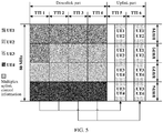
- four terminal devices (UE) are respectively scheduled, four active uplink BWPs are configured for each UE, and a bandwidth of each BWP is 20 MHz.
- the network device configures UE1 to send PUCCH information on a BWP1 and/or a BWP2. That is, the UE1 is configured to transmit uplink PUCCH information and an uplink BWP set that includes the BWP1 and the BWP2.
- the network device configures UE2 to send a PUCCH on the BWP1 and/or the BWP2; and the network device configures UE3 and UE4 to send the PUCCH on a BWP3 and/or a BWP4. Refer to FIG. 5 .
- the PUCCH resource configuration information includes a sequence number of an uplink BWP set.
- a correspondence between the sequence number of the uplink BWP set and included uplink BWPs is shown in following Table 1.
- Table 1 Sequence number of an uplink BWP set Uplink BWPs included in the uplink BWP set 0 BWP1 1 BWP2 2 BWP3 3 BWP4 4 BWP1, BWP2 5 BWP1, BWP3 6 BWP1, BWP4 7 BWP2, BWP3 8 BWP2, BWP4 9 BWP3, BWP4 10 BWP1, BWP2, BWP3 11 BWP1, BWP2, BWP4 12 BWP1, BWP3, BWP4 13 BWP2, BWP3, BWP4 14 BWP1, BWP2, BWP3, BWP4
- Table 1 is merely an example. Actually, some subsets thereof may be selected as an available configuration set.
- the network device configures three active 20 MHz uplink BWPs of for the UE, and a correspondence between a sequence number of an uplink BWP set used for PUCCH information transmission and uplink BWPs included in the uplink BWP set is shown in following Table 2.
- Table 2 Sequence number of an uplink BWP set Uplink BWPs included in the uplink BWP set 0 BWP1 1 BWP2 2 BWP3 3 BWP1, BWP2 4 BWP1, BWP3 5 BWP2, BWP3 6 BWP1, BWP2, BWP3
- the network device may configure more active uplink BWPs for the terminal device, such as eight active uplink BWPs.
- Table 2 may be further expanded. This is not limited in this embodiment of this application.
- the network device may configure different quantities of active uplink BWPs for different terminal devices.
- the network device configures three active 20 MHz uplink BWPs for the UE1, configures two active 20 MHz uplink BWPs for the UE2, and configures four active 20 MHz uplink BWPs for the UE3. This is not limited in this embodiment of this application.
- the active uplink BWP set configured by the network device for each terminal device may include a same uplink BWP.
- the PUCCH resource configuration information may further include time domain information, to be specific, a location of a subframe or a slot in which the PUCCH is located and a symbol location in the subframe or slot; may further include location information of a candidate transmission frequency domain resource (a frequency domain resource location in the uplink BWP), for example, a resource interlace index (interlace index); and may further include an orthogonal extension code and the like. This is not limited in this embodiment of this application.
- the location information of the candidate transmission frequency domain resource may be used to indicate which sub-band or which CC the candidate transmission frequency domain resource is. For example, assuming that a basic unit of a BWP is 20 M, the location information of the candidate transmission frequency domain resource may be used to indicate which sub-band in a single wideband carrier or which CC in CA the BWP is. In another implementation, the location information of the candidate transmission frequency domain resource may alternatively be used to indicate which frequency resources in a BWP are to-be-occupied, and for example, indicate which frequency domain resources in a 20 MHz BWP are to-be-occupied.
- ACK/NACK information corresponding to a subframe 1 and a subframe 2 in a time domain is located at last two orthogonal frequency division multiplexing (orthogonal frequency division multiplexing, OFDM) symbols of a subframe 5, and ACK/NACK information of a subframe 3 and a subframe 4 is located at last two OFDM symbols of a subframe 6.
- OFDM orthogonal frequency division multiplexing
- the PUCCH resource configuration information may be semi-statically configured by the network device in advance; or may be dynamically indicated by the network device in downlink control information sent to the terminal device, that is, be carried in the downlink control information; or may be configured in a mixed manner. This is not limited in this embodiment of this application.
- the downlink control information may be DCI (downlink control information) defined in an LTE system, or may be downlink control information of another name defined in a future communications system. Particularly, the foregoing indication information of the uplink BWP set may be carried in the downlink control information.
- the terminal device may directly determine uplink BWPs included in the BWP set through table lookup based on the sequence number of the BWP set.
- the terminal device may obtain by calculation a corresponding sequence number of the BWP set from a sequence number of a PUCCH resource based on a preset formula, and determine included uplink BWPs through table lookup.
- the terminal device may further determine other information, such as time domain information, a frequency domain resource location in the uplink BWP, orthogonal extension code information, and the like, based on the PUCCH resource configuration information.
- the terminal device determines, based on a downlink transmission resource, the one or more candidate transmission frequency domain resources used for PUCCH information transmission.
- the network device determines a correspondence between the downlink transmission resource and the candidate transmission frequency domain resource set, that is, bonds the downlink transmission resource of the scheduled terminal device and the uplink BWP set.
- the correspondence between the downlink transmission resource and the uplink BWP set may be set by a protocol, and is known to both the network device and the terminal device, or may be set by the network device, and the correspondence between the downlink transmission resource and the uplink BWP set is notified to the terminal device in advance so that the terminal device, in a case of learning of the downlink transmission resource, may determine the uplink BWP set based on the correspondence and the downlink transmission resource.
- a downlink transmission bandwidth allocated for the UE1 in the subframe 1 and the subframe 2 includes the BWP1 and the BWP2, and therefore, an uplink BWP set corresponding to the UE1 in the subframe 5 includes the BWP1 and the BWP2; and a downlink transmission bandwidth allocated for the UE1 in the subframe 3 and the subframe 4 includes only the BWP1, and therefore, an uplink BWP set corresponding to the UE1 in the subframe 6 includes only the BWP1.
- an uplink BWP set corresponding to the UE 2 in the subframe 5 and the subframe 6 includes only the BWP2; an uplink BWP set corresponding to the UE 3 in both the subframe 5 and the subframe 6 includes only the BWP 3; and an uplink BWP set corresponding to the UE4 in the subframe 5 includes only the BWP 4, and an uplink BWP set corresponding to the UE4 in the subframe 6 includes the BWP 3 and the BWP 4.
- the terminal device determines the uplink BWP set based on the learned downlink transmission resource and the correspondence between the downlink transmission resource and the uplink BWP set, that is, determines the one or more candidate transmission frequency domain resources.
- Step S402 Determine, based on a sensing result of the candidate transmission frequency domain resources, a transmission frequency domain resource used for PUCCH information transmission.
- the terminal device performs idle state sensing on the uplink BWPs included in the uplink BWP set, it is possible that some uplink BWPs are in an idle state, and some uplink BWPs are in an occupied state, or all uplink BWPs are in an idle state, or all uplink BWPs are in an occupied state, or the like.
- the terminal device abandons this PUCCH information transmission.
- the terminal device determines the candidate transmission frequency domain resource in an idle state as a transmission frequency domain resource used for PUCCH information transmission.
- the terminal device selects one candidate transmission frequency domain resource from the at least two candidate transmission frequency domain resources based on an identifier of the terminal device, and determines the selected candidate transmission frequency domain resource as a transmission domain resource used for PUCCH information transmission. For example, the terminal device determines, based on UE identification (identification, ID), the transmission frequency domain resource used for PUCCH information transmission in the at least two candidate transmission frequency domain resources. Assuming that the UE1 passes LBT on both the BWP1 and the BWP2, a quantity of available BWPs is 2.
- the UE1 performs a modulo operation on 2 with its UE ID, and if a remainder is 0, determines the BWP1 as the transmission frequency domain resource used for PUCCH information transmission; and if a remainder is 1, determines the BWP2 as the transmission frequency domain resource used for PUCCH information transmission.
- another manner may be used for a correspondence between the remainder and the transmission frequency domain resource used for PUCCH information transmission. For example, if the remainder is 1, the BWP1 is determined as the transmission frequency domain resource used for PUCCH information transmission; and if the remainder is 0, the BWP2 is determined as the transmission frequency domain resource used for PUCCH information transmission.
- a specific correspondence between the remainder and the transmission frequency domain resource used for PUCCH information transmission is not limited in this embodiment of this application.
- the terminal device may autonomously and randomly select one candidate transmission frequency domain resource from the at least two candidate transmission frequency domain resources based on an identifier of the terminal device, and determine the selected candidate transmission frequency domain resource as a transmission domain resource used for PUCCH information transmission.
- the network device needs to receive the PUCCH information on all the BWPs included in the candidate transmission frequency domain resources.
- the network device needs to perform blind detection, possibly resulting in introduction of an extra latency.
- the terminal device determines all candidate transmission frequency domain resources in an idle state as transmission frequency domain resources used for PUCCH information transmission.
- both the BWP1 and the BWP2 are determined as the transmission frequency domain resources used for PUCCH information transmission.
- the UE1 repeatedly sends the PUCCH information on the BWP1 and the BWP2, that is, the PUCCH information is sent on the BWP1, and is also sent on the BWP2.
- the network device does not need to perform blind detection, and may directly combine and receive the PUCCH information on all the BWPs included in the candidate transmission frequency domain resource set, so that receiving efficiency of the network device is improved. In another implementation, the network device may still receive the PUCCH information in a blind detection manner.
- Step S403 Transmit the PUCCH information by using the determined transmission frequency domain resource
- the terminal device transmits the PUCCH information by using the determined transmission frequency domain resource, and for example, transmits the PUCCH information to the network device by using the determined transmission frequency domain resource.
- the PUCCH information is transmitted by using the transmission frequency domain resource; and if two or more transmission frequency domain resources are determined, then the PUCCH information is transmitted by using two or more transmission frequency domain resources.
- the terminal device after determining the one or more candidate transmission frequency domain resources, the terminal device performs idle state sensing on the one or more candidate transmission frequency domain resources, determines, based on a sensing result, the transmission frequency domain resource used for PUCCH information transmission, and finally, transmits the PUCCH information by using the determined transmission frequency domain resource, so that uplink transmission can be implemented by using an unlicensed licensed frequency spectrum, and transmission efficiency can be improved.
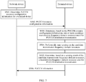
- FIG. 7 is a schematic flowchart of another transmission method according to an embodiment of this application.
- a network device directly indicates one or more candidate transmission frequency domain resources by using PUCCH resource configuration information.
- the method is described from a perspective of interaction between a terminal device and a network device. The method may include, but is not limited to, the following steps.
- Step S501 The network device determines PUCCH resource configuration information for the terminal device.
- the network device configures the PUCCH resource configuration information for the terminal device.
- the PUCCH resource configuration information includes information of one or more candidate transmission frequency domain resources used to indicate the one or more candidate transmission frequency domain resources.
- the indication information may directly indicate the one or more candidate transmission frequency domain resources, for example, indicate an identifier or identifiers of one or more BWPs, or for another example, indicate a BWP set identifier, and the terminal device may determine the one or more candidate transmission frequency domain resources based on a correspondence between the set identifier and the included BWPs.
- the indication information may also indirectly indicate the one or more candidate transmission frequency domain resources.
- the network device may configure different quantities of active uplink BWPs for different terminal devices.
- the network device configures three active 20 MHz uplink BWPs for a UE1, configures two active 20 MHz uplink BWPs for a UE2, and configures four active 20 MHz uplink BWPs for a UE3. This is not limited in this embodiment of this application.
- the active uplink BWP set configured by the network device for each terminal device may include a same uplink BWP.
- the PUCCH resource configuration information may further include time domain information, to be specific, a location of a subframe or a slot at which the PUCCH is located and a symbol location in the subframe or the slot; may further include location information, such as an interlace index, of a candidate transmission frequency domain resource (a frequency domain resource location in the uplink BWP); and may further include an orthogonal extension code. This is not limited in this embodiment of this application.
- the location information of the candidate transmission frequency domain resource may be used to indicate which sub-band or which CC the candidate transmission frequency domain resource is. For example, assuming that a basic unit of a BWP is 20 M, the location information of the candidate transmission frequency domain resource may be used to indicate which sub-band in a single wideband carrier or which CC in CA the BWP is. In another implementation, the location information of the candidate transmission frequency domain resource may alternatively be used to indicate which frequency resources in a BWP are to-be-occupied, and for example, indicate which frequency domain resources in a 20 M BWP are to-be-occupied.
- Step S502 The network device sends the PUCCH resource configuration information to the terminal device.
- the network device may send the foregoing PUCCH resource configuration information to the terminal device by using radio resource control (radio resource control, RRC) signaling; or may send the foregoing PUCCH resource configuration information to the terminal device by using downlink control information, that is, dynamically indicate the foregoing PUCCH resource configuration information by using the downlink control information; or may send the PUCCH resource configuration information to the terminal device in another manner.
- radio resource control radio resource control, RRC
- Step S503 The terminal device determines, based on the PUCCH resource configuration information, the one or more candidate transmission frequency domain resources used for PUCCH information transmission.
- the terminal device determines the uplink BWPs included in the uplink BWP set through table lookup based on a sequence number of the uplink BWP set.
- the terminal device may obtain by calculation a corresponding sequence number of the BWP set from a sequence number of a PUCCH resource based on a preset formula, and determine the uplink BWPs included in the BWP set through table lookup.
- Step S504 The terminal device performs idle state sensing on the candidate transmission frequency domain resources.
- Step S505 The terminal device determines a transmission frequency domain resource used for PUCCH information transmission based on a sensing result of the candidate transmission frequency domain resources.
- Step S506 The terminal device transmits the PUCCH information to the network device by using the determined transmission frequency domain resource.
- step S504 to step S506 in the embodiment shown in FIG. 7 For a specific implementation process of step S504 to step S506 in the embodiment shown in FIG. 7 , refer to step S401 to step S403 in the embodiment shown in FIG. 4 . Details are not described herein again.
- the terminal device determines the one or more candidate transmission frequency domain resources used for PUCCH information transmission based on the PUCCH resource configuration information, so that uplink transmission can be implemented by using an unlicensed frequency spectrum, and transmission efficiency can be improved.
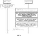
- FIG. 8 is a schematic flowchart of still another transmission method according to an embodiment of this application.
- a network device directly indicates one or more candidate transmission frequency domain resources by using a correspondence between a downlink transmission resource and an uplink BWP set.
- the method is described from a perspective of interaction between a terminal device and a network device. The method may include, but is not limited to, the following steps.
- Step S601 The network device determines a downlink transmission resource dedicated for the terminal device.
- the network device allocates downlink transmission bandwidths for all uplink transmission subframes of the terminal device.
- downlink transmission bandwidths allocated to a subframe 1 and a subframe 2 of UE1 include a BWP1 and a BWP2.
- the network device may configure a correspondence between the downlink transmission resource and the uplink BWP set.
- one downlink transmission resource corresponds to one uplink BWP set.
- the correspondence between the downlink transmission resource and the uplink BWP set may also be set by a protocol.
- Step S602 The terminal device obtains the downlink transmission resource.
- the terminal device may obtain the downlink transmission resource based on downlink transmission resource configuration information sent by the network device. For example, the terminal device may receive the downlink transmission resource from the network device.
- the terminal device obtains the correspondence between the downlink transmission resource and the uplink BWP set from the network device or based on a protocol.
- Step S603 The terminal device determines, based on the downlink transmission resource, one or more candidate transmission frequency domain resources used for PUCCH information transmission.
- the terminal device determines, based on the obtained downlink transmission resource and the correspondence between the downlink transmission resource and the uplink BWP set, the one or more candidate transmission frequency domain resources used for PUCCH information transmission.
- Step S604 The terminal device performs idle state sensing on the candidate transmission frequency domain resources.
- Step S605 The terminal device determines, based on a sensing result of the candidate transmission frequency domain resources, a transmission frequency domain resource used for PUCCH information transmission.
- Step S606 The terminal device transmits the PUCCH information to the network device by using the determined transmission frequency domain resource.
- step S604 to step S606 in the embodiment shown in FIG. 8 For a specific implementation process of step S604 to step S606 in the embodiment shown in FIG. 8 , refer to step S401 to step S403 in the embodiment shown in FIG. 4 . Details are not described herein again.
- the terminal device determines, based on the downlink transmission resource and a bonding relationship between the downlink transmission resource and the uplink BWP set, the one or more candidate transmission frequency domain resources used for PUCCH information transmission, so that uplink transmission can be implemented by using an unlicensed frequency spectrum, and transmission efficiency can be improved.
- FIG. 9 is a simplified schematic diagram 1 of a device according to an embodiment of this application.
- the device may be a terminal device 10, or may be a chip or a circuit, for example, a chip or a circuit that may be disposed in a terminal device.
- the terminal device 10 may correspond to the terminal device in the foregoing methods.
- the device may include a processor 110 and a memory 120.
- the memory 120 is configured to store an instruction.
- the processor 110 is configured to execute the instruction stored in the memory 120, to implement step S401 and step S402 in the method corresponding to FIG. 4 ; step S503 and step S504 in the method corresponding to FIG. 7 ; and step S602 to step S604 in the method corresponding to FIG. 8 .
- the device may further include a receiver 140 and a transmitter 150. Further, the device may further include a bus system 130. The processor 110, the memory 120, the receiver 140, and the transmitter 150 may be connected through the bus system 130.
- the processor 110 is configured to execute an instruction stored in the memory 120, to control the receiver 140 to receive a signal and control the transmitter 150 to send a signal, to complete the steps of the terminal device in the foregoing methods.
- the receiver 140 and the transmitter 150 may be a same physical entity or different physical entities. If being a same physical entity, the receiver 140 and the transmitter 150 may be collectively referred to as a transceiver.
- the memory 220 may be integrated in the processor 210, or may be disposed separately from the processor 210.
- the receiver 140 and the transmitter 150 may be considered to implement functions of the receiver 140 and the transmitter 150 by using a transceiver circuit or a dedicated transceiver chip. It may be considered to implement the processor 110 by using a dedicated processing chip, a processing circuit, a processor, or a general-purpose chip.
- terminal device provided in this embodiment of this application in a manner of using a general-purpose computer. That is, program code for implementing the functions of the processor 110, the receiver 140, and the transmitter 150 is stored in a memory, and a general-purpose processor implements the functions of the processor 110, the receiver 140, and the transmitter 150 by executing the code stored in the memory.
- FIG. 10 is a simplified schematic structural diagram of a terminal device according to an embodiment of this application.
- the terminal device may be applied to the system shown in FIG. 1 .
- FIG. 10 shows only main components of the terminal device.
- the terminal device 10 includes: a processor, a memory, a control circuit, an antenna, and an input/output apparatus.
- the processor is mainly configured to: process a communications protocol and communication data, control the entire terminal device, execute a software program, and process data of the software program, for example, is configured to support the terminal device to perform an action described in the foregoing embodiments of the method for transmitting an indication of a precoding matrix.
- the memory is mainly configured to store the software program and data.
- the control circuit is mainly configured to: convert a baseband signal and a radio frequency signal, and process the radio frequency signal.
- the control circuit together with the antenna may also be referred to as a transceiver, and is mainly configured to receive and send a radio frequency signal in an electromagnetic wave form.
- the input/output apparatus such as a touchscreen, a display, or a keyboard, is mainly configured to: receive data entered by a user and output data to the user.
- the processor may read the software program stored in a storage unit, explain and execute an instruction of the software program, and process the data of the software program.
- the processor outputs a baseband signal to a radio frequency circuit.
- the radio frequency circuit After performing radio frequency processing on the baseband signal, the radio frequency circuit sends the radio frequency signal in a form of electromagnetic wave by using the antenna.
- the radio frequency circuit receives the radio frequency signal by using the antenna, converts the radio frequency signal into a baseband signal, and outputs the baseband signal to the processor.
- the processor converts the baseband signal into data, and processes the data.
- FIG. 10 shows only one memory and one processor.
- the memory may also be referred to as a storage medium, a storage device, or the like. This is not limited in this embodiment of this application.
- the processor may include a baseband processor and a central processing unit.
- the baseband processor is mainly configured to process a communications protocol and communication data.
- the central processing unit is mainly configured to control the entire terminal device, execute a software program, and process data of the software program.
- the processor in FIG. 10 integrates functions of the baseband processor and the central processing unit.
- the baseband processor and the central processing unit may be respectively independent processors, and are interconnected by using technologies such as a bus.
- the terminal device may include a plurality of baseband processors, to adapt to different network standards.
- the terminal device may include a plurality of central processing units, to enhance a processing capability of the terminal device.
- the baseband processor may also be presented as a baseband processing circuit or a baseband processing chip.
- the central processing unit may also be presented as a central processing circuit or a central processing chip.
- a function of processing the communications protocol and the communication data may be built in the processor, or may be stored in the storage unit in a software program form.
- the processor executes the software program, to implement a baseband processing function.
- the antenna having a receiving and transmitting function and the control circuit may be regarded as a transceiver unit 101 of the terminal device 10.
- the processor having a processing function may be regarded as a processing unit 102 of the terminal device 10.
- the terminal 10 includes a transceiver unit 101 and a processing unit 102.
- the transceiver unit may also be referred to as a transceiver, a transceiver device, a transceiver apparatus, and the like.
- a component configured to implement a receiving function in the transceiver unit 101 may be regarded as a receiving unit, and a component configured to implement a sending function in the transceiver unit 101 may be regarded as a sending unit. That is, the transceiver unit 101 includes the receiving unit and the sending unit.
- the receiving unit may also be referred to as a receiving device, a receiver, a receiving circuit, or the like.
- the sending unit may be referred to as a transmitting device, a transmitter, a transmitting circuit, or the like.
- FIG. 11 is a simplified schematic diagram 2 of a device according to an embodiment of this application.
- the device may be a network device 20, or may be a chip or a circuit, such as a chip or a circuit that may be disposed in a network device.
- the network device 20 corresponds to the network device in the foregoing methods.
- the device may include a processor 210 and a memory 220.
- the memory 220 is configured to store an instruction.
- the processor 210 is configured to execute the instruction stored in the memory 220, to implement step S501 in the method corresponding to FIG. 7 ; and step S601 in the method corresponding to FIG. 8 .
- the network may further include a receiver 240 and a transmitter 250. Further, the network may further include a bus system 230.
- the processor 210, the memory 220, the receiver 240, and the transmitter 250 are connected through the bus system 230.
- the processor 210 is configured to execute the instruction stored in the memory 220, to control the receiver 240 to receive a signal and control the transmitter 250 to send the signal, to complete the steps of the network device in the foregoing methods.
- the receiver 240 and the transmitter 250 may be a same physical entity or different physical entities. If being a same physical entity, the receiver 140 and the transmitter 150 may be collectively referred to as a transceiver.
- the memory 220 may be integrated in the processor 210 or may be disposed separately from the processor 210.
- the receiver 240 and the transmitter 250 may be considered to implement functions of the receiver 240 and the transmitter 250 by using a transceiver circuit or a dedicated transceiver chip. It may be considered to implement the processor 210 by using a dedicated processing chip, a processing circuit, a processor, or a general-purpose chip.
- network device provided in this embodiment of this application in a manner of using a general-purpose computer. That is, program code for implementing the functions of the processor 210, the receiver 240, and the transmitter 250 is stored in a memory, and a general-purpose processor implements the functions of the processor 210, the receiver 240, and the transmitter 250 by executing the code stored in the memory.
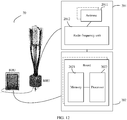
- FIG. 12 is a simplified schematic structural diagram of a network device according to an embodiment of this application, and for example, may be a schematic structural diagram of a base station.
- the base station may be applied to the system shown in FIG. 1 .
- the base station 20 includes one or more radio frequency units, such as a remote radio unit (remote radio unit, RRU) 201 and one or more baseband units (baseband unit, BBU) (also referred to as digital unit, digital unit, DU) 202.
- RRU remote radio unit
- BBU baseband unit
- digital unit, digital unit, DU digital unit
- the RRU 201 may be referred to as a transceiver unit, a transceiver device, a transceiver circuit, a transceiver, or the like, and may include at least one antenna 2011 and a radio frequency unit 2012.
- the RRU 201 is mainly configured to: receive and send radio frequency signals and convert a radio frequency signal and a baseband signal, and for example, is configured to send the signaling message described in the foregoing embodiment to a terminal device.
- the BBU 202 is mainly configured to perform baseband processing, control the base station, and the like.
- the RRU 201 and the BBU 202 may be physically disposed together, or may be physically separately disposed, that is, distributed base stations.
- the BBU 202 is a control center of the base station, and is also referred to as a processing unit, mainly configured to implement a baseband processing function such as channel coding, multiplexing, modulation, and spectrum spreading.
- the BBU (the processing unit) may be configured to control the base station to perform an operation procedure related to the network device in the foregoing embodiments of the methods.
- the BBU 202 may include one or more boards.
- a plurality of boards may jointly support a radio access network (for example, an LTE network) of a single access standard, or may respectively support radio access networks of different access standards.
- the BBU 202 further includes a memory 2021 and a processor 2022.
- the memory 2021 is configured to store a necessary instruction and necessary data.
- the memory 2021 stores preset information, a codebook, and the like in the foregoing embodiments.
- the processor 2022 is configured to control the base station to perform a necessary action, and for example, is configured to control the base station to perform an operation procedure related to a network device in the foregoing embodiments of the methods.
- the memory 2021 and the processor 2022 may serve one or more boards. That is, the memory and the processor may be disposed individually on each board. Alternatively, a plurality of boards may share the same memory and the same processor. In addition, a necessary circuit may be disposed on each board.
- an embodiment of this application further provides a communications system, including the foregoing network device and one or more terminal devices.
- the processor may be a central processing unit (Central Processing Unit, "CPU” for short), or the processor may be another general purpose processor, a digital signal processor (DSP), an application-specific integrated circuit (ASIC), a field programmable gate array (FPGA), or another programmable logic device, discrete gate or transistor logic device, discrete hardware component, or the like.
- the general-purpose processor may be a microprocessor, or the processor may be any conventional processor or the like.
- the memory may include a read-only memory and a random access memory, and provide an instruction and data to the processor.
- a part of the memory may further include a non-volatile random access memory.
- the bus system may further include a power bus, a control bus, a status signal bus, and the like, in addition to a data bus.
- a power bus may further include a power bus, a control bus, a status signal bus, and the like, in addition to a data bus.
- various types of buses in the figure are marked as the bus system.
- steps in the foregoing methods can be implemented by using a hardware integrated logical circuit in the processor, or by using instructions in a form of software.
- the steps of the method disclosed with reference to the embodiments of this application may be directly performed by a hardware processor, or may be performed by using a combination of hardware in the processor and a software module.
- a software module may be located in a mature storage medium in the art, such as a random access memory, a flash memory, a read-only memory, a programmable read-only memory, an electrically erasable programmable memory, a register, or the like.
- the storage medium is located in the memory, and a processor reads information in the memory and completes the steps in the foregoing methods in combination with hardware of the processor. To avoid repetition, details are not described herein again.
- sequence numbers of the foregoing processes do not mean execution sequences in various embodiments of this application.
- the execution sequences of the processes should be determined according to functions and internal logic of the processes, and should not be construed as any limitation on the implementation processes of the embodiments of this application.
- the disclosed system, apparatus, and method may be implemented in other manners.
- the described apparatus embodiment is merely an example.
- the unit division is merely logical function division and may be other division in actual implementation.
- a plurality of units or components may be combined or integrated into another system, or some features may be ignored or not performed.
- the displayed or discussed mutual couplings or direct couplings or communication connections may be implemented by using some interfaces.
- the indirect couplings or communication connections between the apparatuses or units may be implemented in electronic, mechanical, or other forms.
- the units described as separate parts may or may not be physically separate, and parts displayed as units may or may not be physical units, may be located in one position, or may be distributed on a plurality of network units. Some or all of the units may be selected based on actual requirements to achieve the objectives of the solutions of the embodiments.
- All or some of the foregoing embodiments may be implemented by using software, hardware, firmware, or any combination thereof.
- the embodiments may be implemented completely or partially in a form of a computer program product.
- the computer program product includes one or more computer instructions.
- the computer may be a general-purpose computer, a dedicated computer, a computer network, or other programmable apparatuses.
- the computer instructions may be stored in a computer-readable storage medium or may be transmitted from a computer-readable storage medium to another computer-readable storage medium.
- the computer instructions may be transmitted from a website, computer, server, or data center to another website, computer, server, or data center in a wired (for example, a coaxial cable, an optical fiber, or a digital subscriber line (DSL)) or wireless (for example, infrared, radio, and microwave, or the like) manner.
- the computer-readable storage medium may be any usable medium accessible by a computer, or a data storage device, such as a server or a data center, integrating one or more usable media.
- the usable medium may be a magnetic medium (for example, a floppy disk, a hard disk, or a magnetic tape), an optical medium (for example, a digital video disc (digital video disk, DVD)), a semiconductor medium (for example, a solid-state drive (Solid State Disk, SSD)), or the like.
- a magnetic medium for example, a floppy disk, a hard disk, or a magnetic tape
- an optical medium for example, a digital video disc (digital video disk, DVD)
- a semiconductor medium for example, a solid-state drive (Solid State Disk, SSD)
Landscapes
- Engineering & Computer Science (AREA)
- Signal Processing (AREA)
- Computer Networks & Wireless Communication (AREA)
- Mobile Radio Communication Systems (AREA)
Applications Claiming Priority (2)
| Application Number | Priority Date | Filing Date | Title |
|---|---|---|---|
| CN201710586542.5A CN109275191B (zh) | 2017-07-18 | 2017-07-18 | 一种传输方法及其装置 |
| PCT/CN2018/095999 WO2019015590A1 (fr) | 2017-07-18 | 2018-07-17 | Procédé de transmission et dispositif associé |
Publications (2)
| Publication Number | Publication Date |
|---|---|
| EP3657876A1 true EP3657876A1 (fr) | 2020-05-27 |
| EP3657876A4 EP3657876A4 (fr) | 2020-07-08 |
Family
ID=65015415
Family Applications (1)
| Application Number | Title | Priority Date | Filing Date |
|---|---|---|---|
| EP18834967.4A Pending EP3657876A4 (fr) | 2017-07-18 | 2018-07-17 | Procédé de transmission et dispositif associé |
Country Status (5)
| Country | Link |
|---|---|
| US (1) | US11606776B2 (fr) |
| EP (1) | EP3657876A4 (fr) |
| JP (1) | JP7148208B2 (fr) |
| CN (1) | CN109275191B (fr) |
| WO (1) | WO2019015590A1 (fr) |
Families Citing this family (24)
| Publication number | Priority date | Publication date | Assignee | Title |
|---|---|---|---|---|
| CN109699084B (zh) * | 2017-10-20 | 2021-11-09 | 维沃移动通信有限公司 | 非授权频段下的信息传输方法、终端及网络设备 |
| CN110049559B (zh) | 2018-01-17 | 2021-11-12 | 维沃移动通信有限公司 | 侦听指示方法、终端及网络设备 |
| CN110740018B (zh) * | 2018-07-18 | 2021-12-14 | 维沃移动通信有限公司 | 非授权频段上的调度方法、侦听方法和设备 |
| WO2020154871A1 (fr) * | 2019-01-28 | 2020-08-06 | Oppo广东移动通信有限公司 | Procédé de commande de mesure, dispositif terminal, et dispositif de réseau |
| CN113557767B (zh) * | 2019-02-13 | 2022-09-16 | 荣耀终端有限公司 | 用于在省电模式中的上行链路发射的方法和装置 |
| CN111698699A (zh) * | 2019-03-14 | 2020-09-22 | 索尼公司 | 电子设备、无线通信方法和计算机可读存储介质 |
| CN115052354B (zh) * | 2019-03-29 | 2024-02-13 | 中兴通讯股份有限公司 | 传输方法、装置、设备、系统和存储介质 |
| CN113557784B (zh) * | 2019-03-29 | 2024-04-12 | 富士通株式会社 | 上行传输方法、上行调度方法、装置和通信系统 |
| CN113785648B (zh) * | 2019-03-30 | 2024-10-11 | 韦勒斯标准与技术协会公司 | 在未授权频带中执行传输的资源分配方法及使用其的设备 |
| CN111865538B (zh) * | 2019-04-30 | 2023-07-11 | 中国信息通信研究院 | 一种上行信道指示方法和设备 |
| WO2020227907A1 (fr) * | 2019-05-13 | 2020-11-19 | Oppo广东移动通信有限公司 | Procédé et appareil de détermination de ressource et terminal |
| CN112218380A (zh) * | 2019-07-12 | 2021-01-12 | 北京三星通信技术研究有限公司 | 传输harq-ack的方法及设备 |
| US12457084B2 (en) | 2019-07-12 | 2025-10-28 | Samsung Electronics Co., Ltd. | Method and apparatus for transmitting uplink signal in a communication system |
| KR102790761B1 (ko) * | 2019-07-16 | 2025-04-02 | 베이징 시아오미 모바일 소프트웨어 컴퍼니 리미티드 | 자원 할당 방법, 장치 및 저장 매체(resource allocation method and apparatus, and storage medium) |
| US11968716B2 (en) * | 2019-07-23 | 2024-04-23 | Beijing Xiaomi Mobile Software Co., Ltd. | Information configuration methods, and information reporting methods, base station, and user equipment |
| CN112312546B (zh) * | 2019-07-26 | 2025-01-24 | 中国移动通信有限公司研究院 | 物理上行控制信道的传输、配置方法、终端及网络设备 |
| CN111835487B (zh) * | 2019-08-13 | 2022-07-01 | 维沃移动通信有限公司 | 一种信息处理方法、设备及计算机可读存储介质 |
| US11968670B2 (en) * | 2019-10-04 | 2024-04-23 | Qualcomm Incorporated | Physical uplink control channel (PUCCH) resource selection |
| CN113973388B (zh) * | 2020-07-22 | 2025-04-25 | 维沃移动通信有限公司 | 取消传输的方法、终端及网络侧设备 |
| WO2022077396A1 (fr) * | 2020-10-15 | 2022-04-21 | 华为技术有限公司 | Procédé d'envoi et procédé de réception d'informations de commande de liaison montante, et appareil de communication |
| CN114554600B (zh) * | 2020-11-27 | 2024-11-19 | 大唐移动通信设备有限公司 | 一种分配pucch资源的方法、基站及存储介质 |
| CN115734351B (zh) * | 2021-08-26 | 2026-04-07 | 维沃移动通信有限公司 | 传输方法、装置、终端及网络设备 |
| CN113973385B (zh) * | 2021-12-27 | 2022-03-01 | 成都爱瑞无线科技有限公司 | 非授权频段资源的管理方法、系统、装置及存储介质 |
| EP4525534A4 (fr) * | 2022-05-12 | 2025-07-16 | Beijing Xiaomi Mobile Software Co Ltd | Procédé et appareil de configuration de ressources |
Family Cites Families (15)
| Publication number | Priority date | Publication date | Assignee | Title |
|---|---|---|---|---|
| CN101827425B (zh) * | 2010-04-21 | 2012-09-05 | 新邮通信设备有限公司 | 一种上行发送数据的方法和系统 |
| JP5895008B2 (ja) | 2011-03-18 | 2016-03-30 | エルジー エレクトロニクス インコーポレイティド | 無線通信システムにおける制御情報の伝送方法及び装置 |
| CN105101300A (zh) * | 2014-05-09 | 2015-11-25 | 中兴通讯股份有限公司 | 基于竞争的资源选择方法及装置 |
| WO2016043523A1 (fr) * | 2014-09-18 | 2016-03-24 | 엘지전자 주식회사 | Procédé et dispositif de transmission de signal à un enb et de réception de signal d'un enb par un équipement utilisateur dans un système de communication sans fil prenant en charge l'agrégation de porteuses |
| CN105848165B (zh) * | 2015-01-14 | 2022-01-18 | 中兴通讯股份有限公司 | 非授权资源的使用方法、系统、基站及用户设备 |
| US10015778B2 (en) | 2015-03-17 | 2018-07-03 | Telefonaktiebolaget Lm Ericsson (Publ) | Systems and methods for uplink control information signaling design |
| JP6373209B2 (ja) * | 2015-03-20 | 2018-08-15 | 株式会社ガスター | リーク検査装置リーク検査方法 |
| US10341884B2 (en) * | 2015-07-07 | 2019-07-02 | Qualcomm Incorporated | Channel clearance techniques using shared radio frequency spectrum band |
| CN106470485B (zh) * | 2015-08-14 | 2022-06-14 | 中兴通讯股份有限公司 | 一种无线资源选择方法及终端设备 |
| US11064521B2 (en) * | 2015-10-19 | 2021-07-13 | Apple Inc. | Scheduling uplink transmissions for a user equipment (UE) |
| US20180376456A1 (en) | 2015-12-15 | 2018-12-27 | Nec Corporation | Radio communication system, mobile station, user interface, and display method |
| US10548121B2 (en) * | 2016-02-03 | 2020-01-28 | Comcast Cable Communications, Llc | Downlink and uplink channel transmission and monitoring in a wireless network |
| WO2017171325A1 (fr) * | 2016-03-27 | 2017-10-05 | 엘지전자 주식회사 | Procédé de transmission d'un canal de commande de liaison montante physique dans un système de communication sans fil prenant en charge une bande non-autorisée, et dispositif prenant en charge le procédé de transmission |
| WO2018047887A1 (fr) * | 2016-09-09 | 2018-03-15 | 株式会社Nttドコモ | Terminal d'utilisateur et procédé de radiocommunication |
| US10284404B2 (en) * | 2017-05-26 | 2019-05-07 | Kt Corporation | Method and apparatus for scheduling data channel in new radio |
-
2017
- 2017-07-18 CN CN201710586542.5A patent/CN109275191B/zh active Active
-
2018
- 2018-07-17 WO PCT/CN2018/095999 patent/WO2019015590A1/fr not_active Ceased
- 2018-07-17 EP EP18834967.4A patent/EP3657876A4/fr active Pending
- 2018-07-17 JP JP2020502359A patent/JP7148208B2/ja active Active
-
2020
- 2020-01-17 US US16/746,507 patent/US11606776B2/en active Active
Also Published As
| Publication number | Publication date |
|---|---|
| CN109275191B (zh) | 2021-03-30 |
| EP3657876A4 (fr) | 2020-07-08 |
| CN109275191A (zh) | 2019-01-25 |
| JP7148208B2 (ja) | 2022-10-05 |
| JP2020526996A (ja) | 2020-08-31 |
| US20200154399A1 (en) | 2020-05-14 |
| US11606776B2 (en) | 2023-03-14 |
| WO2019015590A1 (fr) | 2019-01-24 |
Similar Documents
| Publication | Publication Date | Title |
|---|---|---|
| US11606776B2 (en) | Transmission method and apparatus thereof | |
| EP4152866B1 (fr) | Procédé de transmission de signaux, dispositif associé et système | |
| US11425697B2 (en) | Dynamic management of uplink control signaling resources in wireless network | |
| US20200068610A1 (en) | Resource scheduling method, network device, and communications device | |
| CN113228544B (zh) | 用于预配置的上行链路资源的重传方案和优化 | |
| EP3920454A1 (fr) | Procédé, dispositif et système de configuration de direction de transmission | |
| EP3787211A1 (fr) | Procédé de communication et appareil de communication | |
| CN111867116B (zh) | 一种通信方法及装置 | |
| US20210400635A1 (en) | Feedback Signaling for Sidelink | |
| EP3373685A1 (fr) | Procédé et dispositif d'envoi et de réception de rétroaction | |
| US20150349929A1 (en) | Evolved node-b, user equipment, and methods for hybrid automatic repeat request (harq) communication | |
| WO2019037695A1 (fr) | Procédé et appareil de communication | |
| US12382495B2 (en) | Receiver assisted directional channel sensing for NR-U | |
| JP2023517980A (ja) | 通信方法および装置 | |
| WO2022028361A1 (fr) | Procédé et appareil d'accès sans fil | |
| CN112020145A (zh) | 一种通信方法及装置 | |
| US20210204312A1 (en) | Downlink control information transmission method and apparatus | |
| US11343038B2 (en) | Electronic device, wireless communication method and computer readable medium | |
| WO2019129253A1 (fr) | Procédé et dispositif de communication | |
| JP2019169753A (ja) | ユーザ装置及び信号送信方法 | |
| WO2018228501A1 (fr) | Procédé et dispositif de communication | |
| US9894553B2 (en) | Evolved node-B, user equipment and methods for mission-critical machine type communication | |
| EP4171141A1 (fr) | Procédé et appareil de communication | |
| CN103313392B (zh) | 处理控制信道的方法及其通讯装置 | |
| KR20200105404A (ko) | 무선 통신 시스템에서 리소스 풀을 운영하는 방법 및 장치 |
Legal Events
| Date | Code | Title | Description |
|---|---|---|---|
| STAA | Information on the status of an ep patent application or granted ep patent |
Free format text: STATUS: THE INTERNATIONAL PUBLICATION HAS BEEN MADE |
|
| PUAI | Public reference made under article 153(3) epc to a published international application that has entered the european phase |
Free format text: ORIGINAL CODE: 0009012 |
|
| STAA | Information on the status of an ep patent application or granted ep patent |
Free format text: STATUS: REQUEST FOR EXAMINATION WAS MADE |
|
| 17P | Request for examination filed |
Effective date: 20200217 |
|
| AK | Designated contracting states |
Kind code of ref document: A1 Designated state(s): AL AT BE BG CH CY CZ DE DK EE ES FI FR GB GR HR HU IE IS IT LI LT LU LV MC MK MT NL NO PL PT RO RS SE SI SK SM TR |
|
| AX | Request for extension of the european patent |
Extension state: BA ME |
|
| A4 | Supplementary search report drawn up and despatched |
Effective date: 20200608 |
|
| RIC1 | Information provided on ipc code assigned before grant |
Ipc: H04W 74/00 20090101ALN20200602BHEP Ipc: H04L 5/00 20060101ALN20200602BHEP Ipc: H04W 72/12 20090101ALN20200602BHEP Ipc: H04W 72/04 20090101AFI20200602BHEP Ipc: H04W 74/08 20090101ALN20200602BHEP |
|
| DAV | Request for validation of the european patent (deleted) | ||
| DAX | Request for extension of the european patent (deleted) | ||
| STAA | Information on the status of an ep patent application or granted ep patent |
Free format text: STATUS: EXAMINATION IS IN PROGRESS |
|
| 17Q | First examination report despatched |
Effective date: 20220303 |
|
| RIC1 | Information provided on ipc code assigned before grant |
Ipc: H04W 72/04 20090101AFI20260312BHEP Ipc: H04W 72/02 20090101ALI20260312BHEP Ipc: H04W 74/00 20090101ALN20260312BHEP Ipc: H04L 5/00 20060101ALN20260312BHEP Ipc: H04W 72/12 20090101ALN20260312BHEP Ipc: H04W 74/08 20090101ALN20260312BHEP Ipc: H04W 74/0808 20240101ALN20260312BHEP Ipc: H04W 72/0453 20230101ALN20260312BHEP Ipc: H04W 72/21 20230101ALN20260312BHEP |
|
| GRAP | Despatch of communication of intention to grant a patent |
Free format text: ORIGINAL CODE: EPIDOSNIGR1 |
|
| STAA | Information on the status of an ep patent application or granted ep patent |
Free format text: STATUS: GRANT OF PATENT IS INTENDED |