EP3658059B1 - Procédés d'association et systèmes associés pour manipulateurs - Google Patents
Procédés d'association et systèmes associés pour manipulateurs Download PDFInfo
- Publication number
- EP3658059B1 EP3658059B1 EP18838547.0A EP18838547A EP3658059B1 EP 3658059 B1 EP3658059 B1 EP 3658059B1 EP 18838547 A EP18838547 A EP 18838547A EP 3658059 B1 EP3658059 B1 EP 3658059B1
- Authority
- EP
- European Patent Office
- Prior art keywords
- user input
- manipulator
- manipulators
- input system
- input device
- Prior art date
- Legal status (The legal status is an assumption and is not a legal conclusion. Google has not performed a legal analysis and makes no representation as to the accuracy of the status listed.)
- Active
Links
Images


Classifications
-
- A—HUMAN NECESSITIES
- A61—MEDICAL OR VETERINARY SCIENCE; HYGIENE
- A61B—DIAGNOSIS; SURGERY; IDENTIFICATION
- A61B34/00—Computer-aided surgery; Manipulators or robots specially adapted for use in surgery
- A61B34/30—Surgical robots
-
- A—HUMAN NECESSITIES
- A61—MEDICAL OR VETERINARY SCIENCE; HYGIENE
- A61B—DIAGNOSIS; SURGERY; IDENTIFICATION
- A61B34/00—Computer-aided surgery; Manipulators or robots specially adapted for use in surgery
- A61B34/20—Surgical navigation systems; Devices for tracking or guiding surgical instruments, e.g. for frameless stereotaxis
-
- A—HUMAN NECESSITIES
- A61—MEDICAL OR VETERINARY SCIENCE; HYGIENE
- A61B—DIAGNOSIS; SURGERY; IDENTIFICATION
- A61B34/00—Computer-aided surgery; Manipulators or robots specially adapted for use in surgery
- A61B34/30—Surgical robots
- A61B34/32—Surgical robots operating autonomously
-
- A—HUMAN NECESSITIES
- A61—MEDICAL OR VETERINARY SCIENCE; HYGIENE
- A61B—DIAGNOSIS; SURGERY; IDENTIFICATION
- A61B34/00—Computer-aided surgery; Manipulators or robots specially adapted for use in surgery
- A61B34/30—Surgical robots
- A61B34/37—Leader-follower robots
-
- A—HUMAN NECESSITIES
- A61—MEDICAL OR VETERINARY SCIENCE; HYGIENE
- A61B—DIAGNOSIS; SURGERY; IDENTIFICATION
- A61B34/00—Computer-aided surgery; Manipulators or robots specially adapted for use in surgery
- A61B34/70—Manipulators specially adapted for use in surgery
- A61B34/74—Manipulators with manual electric input means
-
- A—HUMAN NECESSITIES
- A61—MEDICAL OR VETERINARY SCIENCE; HYGIENE
- A61B—DIAGNOSIS; SURGERY; IDENTIFICATION
- A61B34/00—Computer-aided surgery; Manipulators or robots specially adapted for use in surgery
- A61B34/70—Manipulators specially adapted for use in surgery
- A61B34/76—Manipulators having means for providing feel, e.g. force or tactile feedback
-
- A—HUMAN NECESSITIES
- A61—MEDICAL OR VETERINARY SCIENCE; HYGIENE
- A61B—DIAGNOSIS; SURGERY; IDENTIFICATION
- A61B90/00—Instruments, implements or accessories specially adapted for surgery or diagnosis and not covered by any of the groups A61B1/00 - A61B50/00, e.g. for luxation treatment or for protecting wound edges
- A61B90/06—Measuring instruments not otherwise provided for
-
- A—HUMAN NECESSITIES
- A61—MEDICAL OR VETERINARY SCIENCE; HYGIENE
- A61B—DIAGNOSIS; SURGERY; IDENTIFICATION
- A61B90/00—Instruments, implements or accessories specially adapted for surgery or diagnosis and not covered by any of the groups A61B1/00 - A61B50/00, e.g. for luxation treatment or for protecting wound edges
- A61B90/36—Image-producing devices or illumination devices not otherwise provided for
- A61B90/37—Surgical systems with images on a monitor during operation
-
- H—ELECTRICITY
- H04—ELECTRIC COMMUNICATION TECHNIQUE
- H04W—WIRELESS COMMUNICATION NETWORKS
- H04W12/00—Security arrangements; Authentication; Protecting privacy or anonymity
- H04W12/50—Secure pairing of devices
-
- A—HUMAN NECESSITIES
- A61—MEDICAL OR VETERINARY SCIENCE; HYGIENE
- A61B—DIAGNOSIS; SURGERY; IDENTIFICATION
- A61B34/00—Computer-aided surgery; Manipulators or robots specially adapted for use in surgery
- A61B34/20—Surgical navigation systems; Devices for tracking or guiding surgical instruments, e.g. for frameless stereotaxis
- A61B2034/2046—Tracking techniques
- A61B2034/2048—Tracking techniques using an accelerometer or inertia sensor
-
- A—HUMAN NECESSITIES
- A61—MEDICAL OR VETERINARY SCIENCE; HYGIENE
- A61B—DIAGNOSIS; SURGERY; IDENTIFICATION
- A61B34/00—Computer-aided surgery; Manipulators or robots specially adapted for use in surgery
- A61B34/20—Surgical navigation systems; Devices for tracking or guiding surgical instruments, e.g. for frameless stereotaxis
- A61B2034/2046—Tracking techniques
- A61B2034/2059—Mechanical position encoders
-
- A—HUMAN NECESSITIES
- A61—MEDICAL OR VETERINARY SCIENCE; HYGIENE
- A61B—DIAGNOSIS; SURGERY; IDENTIFICATION
- A61B34/00—Computer-aided surgery; Manipulators or robots specially adapted for use in surgery
- A61B34/70—Manipulators specially adapted for use in surgery
- A61B34/74—Manipulators with manual electric input means
- A61B2034/742—Joysticks
-
- A—HUMAN NECESSITIES
- A61—MEDICAL OR VETERINARY SCIENCE; HYGIENE
- A61B—DIAGNOSIS; SURGERY; IDENTIFICATION
- A61B90/00—Instruments, implements or accessories specially adapted for surgery or diagnosis and not covered by any of the groups A61B1/00 - A61B50/00, e.g. for luxation treatment or for protecting wound edges
- A61B90/06—Measuring instruments not otherwise provided for
- A61B2090/064—Measuring instruments not otherwise provided for for measuring force, pressure or mechanical tension
- A61B2090/065—Measuring instruments not otherwise provided for for measuring force, pressure or mechanical tension for measuring contact or contact pressure
-
- A—HUMAN NECESSITIES
- A61—MEDICAL OR VETERINARY SCIENCE; HYGIENE
- A61B—DIAGNOSIS; SURGERY; IDENTIFICATION
- A61B90/00—Instruments, implements or accessories specially adapted for surgery or diagnosis and not covered by any of the groups A61B1/00 - A61B50/00, e.g. for luxation treatment or for protecting wound edges
- A61B90/50—Supports for surgical instruments, e.g. articulated arms
- A61B90/57—Accessory clamps
- A61B2090/571—Accessory clamps for clamping a support arm to a bed or other supports
-
- A—HUMAN NECESSITIES
- A61—MEDICAL OR VETERINARY SCIENCE; HYGIENE
- A61B—DIAGNOSIS; SURGERY; IDENTIFICATION
- A61B90/00—Instruments, implements or accessories specially adapted for surgery or diagnosis and not covered by any of the groups A61B1/00 - A61B50/00, e.g. for luxation treatment or for protecting wound edges
- A61B90/36—Image-producing devices or illumination devices not otherwise provided for
- A61B90/361—Image-producing devices, e.g. surgical cameras
Definitions
- This specification relates to association processes and related systems for manipulators, for example, for teleoperated manipulators.
- Robotic manipulators can be operated to control motion of instruments in a workspace.
- such manipulators can be used to perform non-medical and medical procedures.
- teleoperated manipulators can be used to perform minimally invasive surgical procedures.
- An operator can control the manipulators using a user control system, e.g., connected wirelessly or via a wired connection to the teleoperated manipulators.
- the user control system can include multiple user input devices such that each of the teleoperated manipulators can be controlled by a distinct user input device of the user control system. The operator can thus independently control each of the teleoperated manipulators using the user input devices.
- U.S. Patent No. 6,459,926 describes robotic surgical systems which allow selectable independent repositioning of an input handle of a master controller and/or a surgical end effector without corresponding movement of the other. In some cases, independent repositioning is limited to translational degrees of freedom. In other cases, the system provides an input device adjacent a manipulator supporting the surgical instrument so that an assistant can reposition the instrument at the patient's side.
- PCT Publication No. WO201415162A1 describes a hyperdexterous surgical system which includes one or more surgical arms coupleable to a fixture and configured to support one or more surgical tools.
- the system can include an electronic control system configured to communicate electronically with the robotic surgical tools.
- the control system can electronically control the operation of the surgical tools.
- the system can include portable handheld controllers actuatable by a surgeon to communicate one or more control signals to the one or more surgical tools via the electronic control system to operate the surgical tools.
- the portable handheld controllers can provide said control signals from a plurality of locations of an operating arena, allowing a surgeon to be mobile during a surgical procedure and to remotely operate the surgical tools from different locations of the operating arena.
- U.S. Publication No. 2007/0003061 describes a system that may include and/or involve a first device, a second device, and logic to effect pairing of the first and second devices upon detection of physical contact between the devices.
- U.S. Publication No. 2016/0249992 describes a robotized surgery system comprising at least one robot arm which acts under the control of a control console intended for the surgeon.
- the console comprises an eye tracking system for detecting the direction of the surgeon's gaze and for entering commands depending on the directions of the gaze detected.
- the console comprises a screen with at least one zone for viewing the operating field and, among the commands which can be performed depending on the gaze directions, there is an automatic command for enabling or disabling the movement of the robot arm when a gaze direction which falls within or outside of said zone of the screen is detected.
- Other relevant prior art related to the association between two devices based on motion can be found in US 2016/094934 and US 8 750 799 .
- the present invention provides computer-assisted medical system, and a non-transitory computer readable media as defined in the appended independent claims.
- Optional features are defined in the appended dependent claims. The methods mentioned below are not part of the claimed invention.
- a computer-assisted medical system includes teleoperated manipulators, a user input system operable to generate signals to control the manipulators, and a controller configured to execute instructions to perform operations.
- a portion of the user input system is movable relative to the plurality of manipulators.
- the operations include, in a pairing mode, associating a first manipulator of the plurality of manipulators with the portion of the user input system based on movement of the portion of the user input system relative to the first manipulator, and, in a following mode, controlling motion of the first manipulator in accordance with an indication generated by the user input system in response to operation of the portion of the user input system by a user.
- a method of operating a computer-assisted medical system including a plurality of teleoperated manipulators includes, in a pairing mode, associating a first manipulator of the plurality of manipulators with a portion of a user input system based on movement of the portion of the user input system relative to the first manipulator, and, in a following mode, controlling motion of the first manipulator in accordance with an indication generated by the user input system in response to operation of the portion of the user input system by a user.
- a computer-assisted medical system in another aspect, includes teleoperated manipulators, an optical motion detection system operable to generate signals to control the plurality of manipulators, and a controller configured to execute instructions to perform operations.
- the optical motion detection system is configured to detect motion of hands of a user.
- the operations include, in a pairing mode, associating a first manipulator of the plurality of manipulators with a first hand of the user based on movement of the first hand relative to the first manipulator, and, in a following mode, controlling motion of the first manipulator in accordance with an indication generated by the optical motion detection system in response to movement of the first hand of the user.
- associations between portions of the user input system (e.g. one or more user input devices) and the teleoperated manipulators can be formed in an intuitive manner for the operator.
- an operator can initiate association between a user input device and a particular teleoperated manipulator through physical manipulation of the user input device in an intuitive manner.
- the operator can physically move the user input device relative to the teleoperated manipulators to select a manipulator of the teleoperated manipulators to associate with the user input device.
- the user input device can be moved toward or to a position proximate a manipulator to which the user input device is to be associated. This process provides an intuitive way for the operator to associate the user input device.
- Human-detectable feedback can be provided during the pairing mode so that the operator can be kept apprised of states and processes of devices, e.g., the user input devices and the manipulators.
- the controller can generate feedback indicative of association states of the portions of the user input system or association states of the manipulators. Based on the feedback, the operator can initiate association processes for the portions of the user input system that have not already been associated, the manipulators that have not already been associated, or both.
- the controller can generate feedback indicative of a proposed association prior to finalizing an association between a user input device and a manipulator. This can enable the operator to make adjustments to a proposed association, thereby providing the operator with greater control during the association process.
- human-detectable feedback can be continued or newly provided after an association has been made, and indicate the portion of the user input system that is associated with a particular manipulator, and vice versa. Further, the controller can disassociate a user input device or a manipulator in response to user input or a system event.
- the techniques disclosed also apply to non-medical procedures and non-medical instruments.
- the instruments, systems, and methods described herein may be used for non-medical purposes including industrial uses, general robotic uses, manipulation of non-tissue work pieces, and/or cosmetic improvements.
- Other non-surgical applications include use on tissue removed from human or animal anatomies (without return to a human or animal anatomy) or on human or animal cadavers.
- a system 100 in an environment 10 includes a manipulator system 101 including manipulators 102a, 102b, 102c, 102d (collectively referred to as manipulators 102) that can be teleoperated by an operator 104.
- manipulators 102 are termed "teleoperated manipulators” because they that can be teleoperated by an operator 104 through a physically separate user input system 106.
- the manipulators 102 can also be controlled directly through manual interaction with the manipulators 102 themselves.
- "teleoperated manipulators” as used in this application include manipulators that can be controlled only through teleoperation, and manipulators that can be controlled through teleoperation and through direct manual control.
- the manipulators 102 include movable portions that can support instruments (not shown), e.g., surgical and medical instruments.
- the movable portions for example, correspond to distal ends 112a, 112b, 112c, 112d of the manipulators 102.
- the operator 104 can operate a user input system 106 to control motion of the manipulators 102.
- the operator can view a display system 107 that presents imagery representing the instruments mounted on the manipulators 102 while the manipulators 102 are being controlled by the operator 104.
- an instrument including an image capture device such as a camera is mounted to one of the manipulators 102.
- the image capture device generates imagery of the distal ends of other instruments mounted to the other manipulators 102 so that the operator 104 can monitor poses of the distal ends of the instruments during a surgical operation.
- the user input system 106 is connected to the manipulators 102, e.g., wirelessly or using a wired connected.
- the user input system 106 includes multiple distinct portions movable relative to the manipulators 102 and operable for controlling operations of the manipulators 102.
- the user input system 106 includes user input devices 108a, 108b (collectively referred to as user input devices 108) movable relative to the manipulators 102.
- the user input system 106 can include other user input devices, e.g., keyboards, touchscreens, buttons, foot pedals, etc., in addition to the user input devices 108 used to control movement of the manipulators 102 in the following mode. These other user input devices can be used to control the display system 107 and otherwise control operations of the system 100.
- a controller 110 of the system 100 can associate a user input device of the user input system 106 with a corresponding one of the manipulators 102 during an association process.
- the user input device can be operated to control the corresponding manipulator in the following mode to perform an operation, e.g., a medical operation, a surgical operation, a diagnostic operation, etc.
- FIG. 2 shows an example of the manipulator system 101.
- the manipulator system 101 includes a single manipulators or includes three or more manipulators, e.g., four manipulators 102a, 102b, 102c, 102d as depicted in FIG. 1 .
- FIG. 2 is described with respect to the manipulators 102a, 102b, the manipulators 102c, 102d of FIG. 1 can include features similar to those presented with respect to the manipulators 102a, 102b.
- the manipulators 102a, 102b, 102c, 102d may differ in that different instruments may be mounted to the manipulators 102a, 102b, 102c, 102d, and in that the manipulators 102a, 102b, 102c, 102 may be supported by an operating table 105 at different locations along the operating table 105.
- the manipulators 102a, 102b include portions movable about a workspace 114.
- these portions can correspond to distal ends 112a, 112b of the manipulators 102a, 102b that are movable about the workspace 114.
- the distal ends 112a, 112b support instruments 116a, 116b such that the instruments 116a, 116b can be moved about the workspace when the distal ends 112a, 112b are moved about the workspace 114.
- actuation modules 117a, 117b are supportable at the distal ends 112a, 112b of the manipulators 102a, 102b.
- the actuation modules 117a, 117b are removably mounted to the distal ends 112a, 112b of the manipulators 102a, 102b and include one or more actuators operable to generate insertion and roll motions of the instruments 116a, 116b.
- the instruments 116a, 116b are insertable through the actuation modules 117a, 117b such that the instruments 116a, 116b are attached to the actuation modules 117a, 117b, which in turn are attached to the distal ends 112a, 112b of the manipulators 102a, 102b.
- the manipulators 102a, 102b include powered joints 118a, 118b that can be driven to move the distal ends 112a, 112b of the manipulators 102a, 102b about the workspace 114.
- Each of the manipulators 102a, 102b includes multiple powered joints 118a, 118b that enable motion of the distal ends 112a, 112b in multiple degrees of freedom, e.g., pitch, yaw, and roll motions of the distal ends 112a, 112b of the manipulators 102a, 102b.
- the instruments and manipulators described herein can have one or more degrees of freedom that vary in implementations.
- the one or more degrees of freedom include one or more of a yaw motion of the distal portion of the manipulator, a pitch motion of the distal portion of the manipulator, an insertion motion of the instrument supported by the manipulator, a roll motion of the instrument, a yaw motion of the end effector of the instrument, a wrist motion of an end effector of the instrument, or a jaw or grip motion of the end effector of the instrument.
- the system 100 is a computer-assisted system.
- the controller 110 can control operation of the system 100 or operations of portions of the system 100.
- the controller 110 can control operation of the actuators of the powered joints 118a, 118b.
- the distal ends 112a, 112b of the manipulators 102a, 102b, and hence the instruments 116a, 116b can be moved about the workspace 114 when the user input devices 108 (shown in FIG. 1 ) are operated by the operator 104.
- a follower of a manipulator moves in response to movement of a leader. The movement of the follower can emulate the movement of the leader.
- the leader can be one or more of the user input devices 108
- the follower can be one or more components of the manipulator.
- the follower can be an end effector of the manipulator, a remote center of the manipulator, or some other component of the manipulator.
- the distal ends 112a, 112b are the followers.
- actuators of the powered joints 118a, 118b can be controlled to generate motion of links of the manipulators 102a, 102b about the powered joints 118a, 118b, thereby repositioning the distal ends 112a, 112b of the manipulators 102a, 102b.
- the motions of the distal ends 112a, 112b emulate the motions of the user input devices 108.
- the motion of the user input devices 108 in the following mode can cause an instrument mounted to the distal end 112a or 112b to be ejected from the distal end 112a or 112b.
- the system 100 is a medical system to perform a medical procedure on a patient 120.
- the system 100 is a diagnostic system that can be used to perform diagnostics on the patient 120.
- the system 100 is a surgical system that can be used to perform a surgical operation on the patient 120.
- a variety of alternative computer-assisted teleoperated instruments 116a, 116b can be used.
- the teleoperated instruments 116a, 116b can be surgical instruments of different types having differing end effectors.
- the instruments 116a, 116b include multiple DOFs such as, but not limited to, roll, pitch, yaw, insertion depth, opening/closing of jaws, actuation of staple delivery, activation of electro-cautery, and the like. Motion in at least some of such DOFs can be generated by the actuation modules 117a, 117b of the manipulators 102a, 102b to which the instruments 116a, 116b are selectively coupled.
- the instruments 116a, 116b are medical or surgical instruments
- possible end effectors include, for example, DeBakey Forceps, microforceps, and Potts scissors include first and second end effector elements that pivot relative to each other so as to define a pair of end effector jaws.
- Other end effectors including scalpels and electrocautery probes, have a single end effector element.
- the jaws will often be actuated by squeezing the grip members of input devices.
- one or more of the instruments 116a, 116b includes an image capture device, such as a camera.
- the image capture device can capture imagery of other instruments in the workspace, and this imagery can be presented to the operator 104 to allow the operator 104 to visually monitor positions of other instruments in the workspace.
- the system 100 includes an indicator system 122.
- the indicator system 122 includes one or more indicator devices to generate human-perceptible indications to provide feedback to the operator 104 during the association process or during the following mode.
- the indicator system 122 includes indicator devices 124a, 124b.
- the indicator device 124a provides human-perceptible indications originating in the vicinity of the manipulator 102a
- the indicator device 124b provides human-perceptible indications originating in the vicinity of the manipulator 102b.
- the indicator devices 124a, 124b can be attached to, positioned on, or positioned proximate to the manipulators 102a, 102b, respectively.
- the indicator devices 124a, 124b can be located on the actuation modules 117a, 117b and thus can be attached to the manipulators 102a, 102b through the actuation modules 117a, 117b. Alternatively, in some implementations, the indicator devices 124a, 124b are directly attached to or positioned on the manipulators 102a, 102b.
- the indicator system 122 further includes an indicator device 126a (on the user input device 108a shown in FIG. 3A ) and an indicator device 126b (on the user input device 108b shown in FIG. 3B ).
- the indicator device 126a provides human-perceptible indications originating in the vicinity of the user input device 108a
- the indicator device 126b provides human-perceptible indications originating in the vicinity of the user input device 108b.
- the indicator devices 126a, 126b are attached to, positioned on, or positioned proximate to the user input devices 108a, 108b, respectively.
- the indicator devices 124a, 124b, 126a, 126b provide visual feedback
- the indicator devices 124a, 124b, 126a, 126b each includes an appropriate visual feedback device.
- Example visual feedback devices include light-emitting diodes or other light sources, electronic displays such as LCD or OLED displays, etc.
- the indicator devices 124a, 124b, 126a, 126b emit different colors of light to intuitively indicate to the operator the statuses of the user input devices 108a, 108b and the manipulators 102a, 102b.
- the indicator devices 124a, 124b, 126a, 126b present different numeric, textual, or graphical patterns to indicate to the operator the statuses of the user input devices 108a, 108b and the manipulators 102a, 102b. For example, when the pairing mode is initiated, a green light or a flashing "O" can indicate that a device is in an unassociated state, and a red light or a steadily presented (not flashing) "O" can indicate that a device is in an associated state, or vice versa. In some cases, as described herein, a yellow light or a flashing or steadily presented "X" can provide a visual warning, such as to the operator 104.
- the indicator devices 124a, 124b, 126a, 126b can provide visual feedback for indicating additional information about the statuses of the user input devices 108a, 108b and the manipulators 102a, 102b.
- the indicator devices 124a, 124b, 126a, 126b present visual feedback to indicate which user input device recommended to be associated with which manipulator, or to indicate which user input device will be associated with which manipulator upon confirmation.
- both the user input device 108a and the manipulator 102a can flash matching, similar, or identical: color, number, text, graphics, flashing sequence, or other visual feedback.
- the indicator devices 124a, 124b, 126a, 126b present visual feedback to indicate which user input device has been, or is currently, associated with which manipulator.
- both the user input device 108a and the manipulator 102a can steadily present (not flashing) similar or identical: color, number, text, graphical pattern, or other visual feedback.
- this steady presentation of color, number, text, graphics, or other textual feedback can last for the entire duration during which the user input device 108a is associated with the manipulator 102a.
- the indicator devices 124a, 124b, 126a, 126b can provide human-perceptible tactile feedback, aural feedback, or a combination thereof. If the indicator devices 124a, 124b, 126a, 126b provide tactile feedback, the tactile feedback can include vibro-tactile feedback, force feedback, or other forms of feedback associated with a user's sense of touch.
- the indicator devices 124a, 124b, 126a, 126b can include, for example, a vibration generator.
- the indicator devices 126a, 126b can generate vibrations that serve as haptic feedback for the operator 104 when the operator 104 is holding the user input devices 108a, 108b.
- the indicator devices 124a, 124b, 126a, 126b provide aural feedback
- the indicator devices 124a, 124b, 126a, 126b include, for example, an audio output device such a speaker.
- the indicator devices 124a, 124b, 126a, 126b can narrate audible feedback to the operator 104.
- the feedback provided by the indicator devices 124a, 124b, 126a, 126b can be indicative of statuses of the manipulators 102a, 102b and the user input devices 108a, 108b before, during, and after the association process.
- the feedback can be indicative of association states of the manipulators 102a, 102b, association states of the user input devices 108a, 108b, or both.
- An association state can be indicative of whether a particular manipulator is associated with a user input device or whether a particular user input device is associated with a manipulator.
- the indicator devices 124a, 124b, 126a, 126b can provide feedback during an association process to provide the operator 104 with information pertaining to the association process.
- the feedback can be indicative of a proposed association between a user input device and a manipulator.
- the operator 104 can operate the user input devices 108a, 108b to propose an association between a particular user input device and a particular manipulator, and the indicator devices 124a, 124b, 126a, 126b can provide feedback indicative of this proposed association.
- the feedback can be indicative of a usable or an optimal association between a user input device and a manipulator.
- the controller 110 shown in FIG. 1
- the controller 110 can determine usable or optimal associations between the user input devices 108 and the manipulators 102 and provide a signal indicative of the usable or optimal associations.
- the user input device 108a can further include a sensor 128a that can indicate, to the controller 110 (shown in FIG. 1 ), movement of the user input device 108a.
- the sensor 128a can indicate, e.g., generate a signal indicative of, a relative movement between the user input device 108a and the manipulators 102.
- the controller 110 during the pairing mode, can associate a particular manipulator with the user input device 108a in response to the relative movement between the user input device 108a and the particular manipulator satisfying an association condition.
- FIGS. 3A and 3B illustrate an example of manual operation of the user input devices 108a, 108b to associate the user input devices 108a, 108b with the manipulators 102a, 102b.
- the indicator devices 124a, 124b both provide feedback indicating that the manipulators 102a, 102b are in unassociated states.
- the indicator device 126a also provides feedback indicating that the user input device 108a was not previously associated with a manipulator.
- the user input device 108a is moved relative to the manipulator 102a. For example, the user input device 108a is moved to a region proximate the manipulator 102a. Based on this movement of the user input device 108a relative to the manipulator 102a, the controller 110 (shown in FIG. 1 ) associates the manipulator 102a with the user input device 108a.
- the controller 110 can control the indicator devices 124a, 126a to provide human-perceptible feedback indicating that the movement of the user input device 108a relative to the manipulator 102a corresponds to a proposed association between the user input device 108a and the manipulator 102a.
- both the indicator device 124a and the indicator device 126a can provide matching, similar, or identical feedback so that the operator 104 can intuitively understand that the proposed association is between the user input device 108a and the manipulator 102a (and, e.g., not between the user input device 108a and the manipulator 102b). In some cases, this feedback is provided as the operator 104 moves the user input device 108a.
- the operator 104 is able to easily determine when the user input device 108a has been appropriately moved to satisfy the association condition to associate the user input device 108a and the manipulator 102a (and, e.g., to not satisfy the association condition to associate the user input device 108a and the manipulator 102b).
- the operator 104 provides confirmation of the proposed association so that the controller 110 proceeds with associating the manipulator 102a with the user input device 108a.
- the indicator devices 124a, 126a can indicate, after the association is made, that the user input device 108a is associated with the manipulator 102a.
- the indicator devices 124a, 126a provide matching, similar, or identical feedback for part or the entire duration that the user input device 108a is associated with the manipulator 102a.
- the indicator devices 124a, 126a can provide the same color, number, text, graphic, or other visual feedback for the entire duration that the user input device 108a is associated with the manipulator 102a.
- the user input device 108b is moved relative to the manipulator 102b.
- the user input device 108b is moved to a region proximate the manipulator 102b.
- the controller 110 (shown in FIG. 1 ) associates the manipulator 102b with the user input device 108b.
- the user input device 108b associated with the manipulator 102b is distinct from the user input device 108a associated with the manipulator 102a so that the manipulators 102a, 102b can be independently controlled using the user input devices 108a, 108b of the user input system 106.
- the controller 110 can control the indicator devices 124b, 126b to provide human-perceptible feedback indicating that the movement of the user input device 108b relative to the manipulator 102a corresponds to a proposed association between the user input device 108a and the manipulator 102a.
- both the indicator device 124b and the indicator device 126b can provide similar feedback so that the operator 104 can intuitively understand that the proposed association is between the user input device 108b and the manipulator 102b (and, e.g., not between the user input device 108b and the manipulator 102a). In some cases, this feedback is provided as the operator 104 moves the user input device 108b.
- the operator 104 is able to easily determine when the user input device 108b has been appropriately moved to satisfy the association condition to associate the user input device 108b and the manipulator 102b (and, e.g., to not satisfy the association condition to associate the user input device 108a and the manipulator 102b).
- the operator 104 provides confirmation of the proposed association so that the controller 110 proceeds with associating the manipulator 102b with the user input device 108b.
- the indicator devices 124b, 126b can indicate, after the association is made, that the user input device 108b is associated with the manipulator 102b.
- the indicator devices 124a, 126a provide similar or identical feedback for part or the entire duration that the user input device 108b is associated with the manipulator 102b.
- an example of the system 100 for performing an association process includes the manipulator system 101, the controller 110, and the user input system 106. While described with respect to FIGS. 1 , 2 , 3A , and 3B as including two or four manipulators, in some implementations, as shown in FIG. 4 , the manipulator system 101 can include any number of manipulators.
- the manipulator system 101 includes N manipulators (e.g., Manipulator 1 through Manipulator N, collectively referred to as manipulators 102).
- manipulators 102 e.g., Manipulator 1 through Manipulator N, collectively referred to as manipulators 102).
- FIGS. 1 , 2 , 3A , and 3B as including two user input devices, in some implementations, as shown in FIG.
- the user input system 106 includes any number user input devices.
- the user input system 106 includes M user input devices (e.g., User Input Device 1 through User Input Device M, collectively referred to as user input devices 108).
- user input devices 108 include: joysticks, touchscreens, gloves, or handheld remotes.
- the system 100 can further include a sensor system 200.
- the sensor system 200 includes sensors operable to detect movement the user input devices 108.
- the sensor system 200 includes the sensors 128a, 128b (shown in FIGS. 3A and 3B ).
- the sensors in particular, can detect movement of the user input devices 108 that satisfy association conditions for associating a particular user input device with a particular manipulator.
- the sensor system 200 can detect poses, e.g., positions, orientations, or both positions and orientations, of the user input devices 108 and the manipulators 102 in the environment 10.
- Sensors of the sensor system 200 include, for example, infrared sensors, ultrasonic sensors, image capture devices, accelerometers, position encoders, optical sensors, or other appropriate sensors for detecting motion and poses of the manipulators 102 and the user input devices 108. Further examples of association conditions and sensors for detecting these association conditions are described with respect to the process illustrated in FIG. 7 .
- the system 100 can further include a user output system 202 and a memory storage element 204.
- the user output system 202 provides human-perceptible feedback to the operator 104.
- the user output system 202 includes, for example, the indicator system 122 or the display system 107.
- the feedback provided by the user output system 202 can include feedback provided during an association process or during following mode.
- the memory storage element 204 can store data indicative of associations formed between the manipulators 102 and the user input devices 108.
- the controller 110 can retrieve these stored data to determine whether a user input device or a manipulator is in an associated state or an unassociated state.
- the manipulators 102 and the user input devices 108 are associated so that each user input device 108 is associated with a distinct one of the manipulators 102.
- the user input devices 108 can be controlled by the operator 104 so that the associated manipulators can be independently controlled.
- each of the manipulators 102 is associated with a corresponding one of the user input devices 108.
- each of the manipulators 102 can be controlled using the user input devices 108.
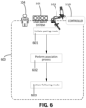
- a process 600 including an association process and a following process is presented with respect to the system 100 described herein.
- the process 600 is performed by the operator 104, the user input system 106, the manipulator system 101, the controller 110, or a combination of the foregoing.
- a pairing mode is initiated.
- the association process is performed to associate a manipulator with a user input device. Examples of further operations and sub-operations the operations 601 and 602 are described with respect to FIGS. 7 , 8A , 8B , and 9 .
- a following mode is initiated so that, in a following process, the manipulator can be controlled in response to manipulation of the user input device.
- the manipulator associated with the user input device at operation 602 can be moved in response to manual operation of the user input device by the operator 104.
- the operator manually manipulates the user input device, which generates a signal or indication received by the controller 110.
- the controller 110 then generates a corresponding signal to move the manipulator of the manipulator system 101 with which the user input device is associated.
- the user input device and the manipulator form a leader-follower system in which the user input device is a leader device and the manipulator is a follower device, thereby enabling the manipulator to be teleoperated through operation of the user input device.
- the system 100 is a surgical system, an instrument supported by the manipulator can be controlled to perform a surgical operation on a patient.
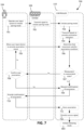
- FIG. 7 illustrates an example of a process 700 to associate a user input device of the user input system 106 with a manipulator of the manipulator system 101.
- the process 700 is performed, for example, during the operations 601 and 602 described with respect to the process 600.
- Operations 701-703 of FIG. 7 illustrate an example process of initiating a pairing mode.
- the operator 104 operates the user input system 106 to initiate the pairing mode.
- the user input system 106 includes a user input device dedicated to initialization of the pairing mode. This user input device can be distinct from the user input devices that are associated to manipulators.
- the user input system 106 transmits a signal to the controller 110 to initiate the pairing mode, e.g., in response to the operator 104 operating the user input system 106 to initiate the pairing mode.
- the controller 110 initiates the pairing mode, e.g., in response to the signal transmitted at the operation 702.
- the operator 104 provides an association intent to associate a particular user input device with a particular manipulator.
- feedback is provided to the operator 104 so that the operator 104 can be kept informed of states of the manipulators of the manipulator system 101 and the user input devices of the user input system 106.
- Operations 704-712 illustrate examples of operations that occur during the pairing mode and in which the foregoing can occur.
- the controller 110 transmits signals to provide association indicators to the operator 104.
- the signals can be transmitted to the user output system 202 (shown in FIG. 4 ), e.g., the indicator system 122 (shown in FIGS. 3A and 3B ) or the display system 107 (shown in FIG. 1 ).
- the user output system 202 presents the association indicators to indicate an association state of each of the manipulators of the manipulator system 101 and an association state of each of the user input devices of the user input system 106.
- the operator 104 moves a user input device (e.g., one of the user input devices 108 described with respect to FIG. 4 ) to provide an association intent.
- the movement of the user input device corresponds to an intent to associate the user input device with a manipulator of the manipulator system 101 (e.g., one of the manipulators 102 described with respect to FIG. 4 ).
- a signal indicative of the movement of the user input device is transmitted to the controller 110.
- the signal is transmitted by the sensor system 200 (shown in FIG. 4 ) to the controller 110.
- association conditions can vary between implementations.
- the association condition includes contact between a particular user input device and a particular manipulator.
- the sensor system 200 includes a contact sensor, e.g., a capacitive sensor, that detects contact between the user input device and the manipulator intended to be associated with the user input device.
- the contact sensor can be attached to or positioned on the user input device or the manipulator.
- the user input device includes a contact sensor, and the manipulator also includes a contact sensor. The association condition is satisfied when the contact sensors detect contact with one another.
- the association condition includes proximity between the user input device and the manipulator.
- the association condition is satisfied when the user input device is move to a region within a predefined distance from the manipulator, e.g., within 5 cm, within 10 cm, within 20 cm, within 30 cm, or within 50 cm.
- the sensor system 200 includes a proximity sensor that detects when the user input device is moved to within the predefined distance.
- the proximity sensor can include a sensor to detect the distance between the user input device and the manipulator, e.g., a time-of-flight sensor, an infrared sensor, or an ultrasonic sensor.
- the proximity sensor includes a sensor attached to one of the manipulator or the user input device and a detectable tag on the other of the manipulator or the user input device.
- the sensor can be a radiofrequency detector, and the tag can be a radiofrequency tag.
- the association condition includes a motion of the user input device directed toward a region defined by a location of the manipulator in the workspace.
- each of the manipulators defines a corresponding volume.
- the volume defined by a manipulator can be within the workspace of the manipulator or can extend outside of the workspace. In some cases, the volume is defined by physical surface of the manipulator.
- the motion of the user input device includes a direction, e.g., a direction of a velocity or acceleration of the user input device.
- the association condition for a manipulator is satisfied when the direction of the motion is directed toward the volume defined by the manipulator, e.g., the ray defined by the direction of the motion intersects with the volume.
- the sensor can be an accelerometer coupled to the user input device.
- the accelerometer can detect the direction of the motion of the user input device.
- locations of the multiple manipulators define multiple distinct regions. The operator moves the user input device toward a first region to satisfy the association condition for a first manipulator, and the operator moves the user input device toward a second region to satisfy the association condition for a second manipulator.
- an image capture device of the sensor system 200 captures imagery of the environment 10 (shown in FIG. 1 ). Contact, proximity, and direction of movement can be determined using image analysis of the captured imagery.
- the image capture device can be a stationary camera positioned to capture imagery of the manipulator system 101 and the user input system 106.
- the movement of the user input device in the pairing mode corresponds to ambiguous movement that does not satisfy a single association condition for a single manipulator.
- the association conditions for multiple manipulators are satisfied due to a single motion of the user input device.
- the controller 110 does not associate a manipulator with the user input device until an association condition of only one of the manipulators is fulfilled.
- the controller 110 can control the user output system 202 to provide feedback to the operator 104 indicative of the ambiguity.
- indicator devices of the manipulators for which the association conditions are satisfied are activated. Multiple indicator devices of the manipulators being activated can be indicative of ambiguity, and the operator 104 can adjust movement of the user input device or can generate other motions of the user input device to resolve the ambiguity.
- the movement of the user input device in the pairing mode corresponds to a movement that does not satisfy an association condition for any manipulator.
- the controller 110 can operate the user output system 202 to provide feedback to the operator 104, e.g., to guide the operator to move the user input device in a manner that fulfills an association condition of one of the manipulators.
- the indicator device for the user input device can provide a warning indication.
- the indicator device emits a yellow light to provide the warning indicator to the operator 104.
- the controller 110 determines an association state of the manipulator.
- the controller 110 determines whether the manipulator is in an unassociated state. For example, the controller 110 can access the memory storage element 204 (shown in FIG. 4 ) to determine whether an association for the manipulator has been stored on the memory storage element 204. If the manipulator is not in an unassociated state, e.g., in an associated state, the operator 104 at operation 708 either confirms that a new association is to be provided to the manipulator or indicates that the manipulator should maintain the stored association. If the operator 104 confirms that a new association is to be provided, the controller 110 can remove the stored association for the manipulator.
- the controller 110 at operation 709 requests for confirmation of an association between the user input device and the manipulator. For example, the controller 110 transmits data representing the request for confirmation to the user output system 202.
- the indicator device on the user input device and the indicator device on the manipulator both provide a feedback pattern indicative of a pending association. If the indicator devices are light indicator devices, the indicator devices can both flash a same color (e.g. green), number, text, graphics, or in a same time sequence, or provide some other visual feedback to indicate that the condition for association between the manipulator and the user input device has been satisfied and confirmation from the operator 104 is requested.
- the operator 104 provides the confirmation of the association.
- the operator 104 can provide this confirmation by performing a specific manipulation of the user input device to confirm the association.
- the specific manipulation can include a movement of the user input device detectable by the sensor system 200, e.g., shaking the user input device up-and-down or directing a movement of the user input device towards the display system 107.
- the specific manipulation can include a manipulation of the user input device for controlling motion of the manipulator in a following mode. For example, if the user input device includes a joystick, a button, knob, or other user input element, the operator 104 can operate the user input element to confirm the association.
- the controller 110 stores the association, e.g., in the memory storage element 204.
- the controller 110 then provides a success signal at operation 712.
- the user output system 202 is operated to provide a human-perceptible signal indicative of the success of the association between the manipulator and the user input element.
- the operations 704-712 can be repeated to associate other user input devices of the user input system 106 with other manipulators of the manipulator system 101.
- the system 100 can remain in the pairing mode until the operator 104 operates the user input system 106 to provide input indicative of initiating the following mode, e.g., initiating operation 603.
- the user input devices that have been associated with the manipulators can be operated by the operator 104 to control movement of the manipulators.
- the controller 110 can provide recommendations to optimize the associations formed between the manipulators and the user input devices.
- Process 800 of FIG. 8A illustrates an example process to provide such a recommendation.
- the process 800 is initiated after the pairing mode is initiated.
- the user input system 106 transmits signals indicative of poses of the user input devices of the user input system 106, e.g., poses of the user input devices in the environment 10 (shown in FIG. 1 ).
- the manipulator system 101 transmits signals indicative of poses of the manipulators of the manipulator system 101 to the controller 110.
- the controller 110 receives these signals from the user input system 106 and the manipulator system 101.
- the sensor system 200 detects the poses of the user input devices, the manipulators, or both and transmits these signals to the controller 110.
- the controller 110 further receives a signal indicative of the position and the orientation of the image capture device, e.g., on the instrument supported on the manipulator 102c.
- the controller 110 receives the signals and uses kinematic modeling to determine the positions and orientations of the manipulators 102a, 102b, the positions and orientations of the instruments 116a, 116b, and the position and orientation of the image capture device.
- one or more signals are generated by sensors of the manipulators (e.g., the manipulators 102a, 102b, and the manipulator to which the image capture device is mounted) or sensors of the instruments (e.g., the instruments 116a, 116b, and the image capture device).
- the sensors of the manipulators include, for example, accelerometers, gyroscopes, encoders, or other sensors associated with joints of the manipulators 102a, 102b.
- the sensors of the instruments include, for example, shape sensors through shafts of the instruments.
- the positions and orientations of the manipulators and/or the positions and orientations of the instruments are determined based on one or more signals from optical sensors (e.g., image capture devices).
- optical sensors e.g., image capture devices.
- the manipulators or the instruments are equipped with optical fiducials detectable by the optical sensors.
- the controller 110 determines usable or optimal associations between the manipulators of the manipulator system 101 and the user input devices of the user input system 106.
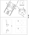
- FIG. 8B illustrates an example in which the manipulators 102a, 102b (shown on the right portion of FIG. 8B ) support the instruments 116a, 116b, respectively (shown on the left portion of FIG. 8B ).
- the display system 107 presents imagery captured by an instrument (not shown) with an image capture device supported by the manipulator 102c.
- FIG. 8B includes a right portion diagrammatically depicting relative positions of the display system 107 and the user input devices 108, and a left portion showing a top view of the system 100.
- the instrument 116a appears on a left portion of imagery presented on the display system 107
- the instrument 116b appears on a right portion of the imagery.
- the controller 110 provides a recommendation to associate the user input device 108a (in the left hand of the operator 104) with the instrument 116a on the left portion of the imagery.
- the controller 110 provides a recommendation to associate the user input device 108b (in the right hand of the operator 104) with the instrument 116b on the right portion of the imagery.
- the controller 110 can determine the relative positions and orientations of the user input devices 108a, 108b and the manipulators 102a, 102b based on the signals indicative of the poses of these devices.
- the controller 110 determines the positions and orientations of the user input devices 108a, 108b relative to the instruments 116a, 116b supported by the manipulators 102a, 102b.
- the controller 110 further receives a signal indicative of the position and the orientation of the image capture device, e.g., on the instrument supported on the manipulator 102c.
- the controller 110 can determine relative poses of the instruments 116a, 116b as they would appear to the operator 104 on the display system 107.
- the controller 110 can determine a recommendation for the associations between the user input devices 108a, 108b and the manipulators 102a, 102b based on these relative poses.
- the recommendation may include recommended associations for a subset or all of the user input devices (e.g. 108a, 108b) and a subset or all of the manipulators (102a, 102b).
- the recommendations may indicate degrees of recommendation for a particular association, such as: a more recommended association between a user input device and a manipulator (e.g. between the user input device 108a and the manipulator holding the instrument 116a), a less recommended association between a user input device and a manipulator (e.g. between the user input device 108a and a manipulator holding an instrument not shown in the imagery), or a not recommended association between a user input device and a manipulator (e.g. the user input device 108a and a manipulator holding the instrument 116b).
- the controller 110 does not receive positions and orientations of the user input devices 108a, 108b for determining the recommendations.
- the user input devices 108a, 108b can be configured such that the user input devices 108a, 108b have fixed positions and orientations relative to one another.
- the controller 110 can provide a recommendation based on the positions and orientations of the manipulators 102a, 102b relative to one another or based on the positions and orientations of the instruments 116a, 116b relative to one another.
- the controller 110 determines the optimal associations, the controller 110 at operation 805 provides a signal to indicate the optimal associations to the operator 104.
- the controller 110 controls the user output system 202 to provide an appropriate signal to guide the operator 104 to form the optimal associations between the manipulators 102a, 102b and the user input devices 108a, 108b.
- the manipulators 102a, 102b and the user input devices 108a, 108b include light indicator devices
- the light indicator devices for corresponding devices that the controller 110 recommends associating can emit like optical signals, e.g., optical signals having a similar color. These optical signals can be distinct from the optical signals emitted by the light indicator devices of other corresponding devices that the controller 110 recommends associating.
- optical signals can thus provide guidance to the operator 104 to intuitively form the optimal associations, e.g., using the process 700.
- the controller 110 automatically forms the associations between the manipulators 102a, 102b and the user input devices 108a, 108b based on the determined optimal associations.
- the controller 110 can determine a pose of a portion of the user input device relative to a pose of the manipulator.
- the portion of the user input device is manually operable by the operator 104 to control movement of the manipulator during the following mode.
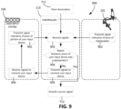
- the portion of the user input device can be reoriented or repositioned. Process 900 of FIG. 9 is performed to achieve this reorienting or repositioning of a portion of a user input device.
- the user input system 106 transmits a signal indicative of a pose of a portion of a user input device of the user input system 106.
- the signal is indicative of the position and orientation of the portion of the user input device relative to the full range of motion of the portion.
- a position sensor coupled to the portion of the user input device can generate the signal.
- the manipulator system 101 transmits a signal indicative of a pose of a manipulator of the manipulator system 101.
- Position sensors of the manipulator e.g., encoders, accelerometers, etc., can generate and transmit the signal.
- the controller 110 receives these signals from the user input system 106 and the manipulator system 101.
- the controller 110 determines whether a pose of the user input device relative to a full range of motion of the portion matches with a pose of the manipulator relative to a full range of motion of the manipulator.
- the user input device can have a degree of freedom of motion for controlling yaw motion of the distal end of the manipulator.
- the controller 110 determines whether the position of the user input device within the full range of motion for this degree of freedom of motion matches with the position of the distal end of the manipulator within the full range of motion for its yaw degree of freedom.
- the controller 110 similarly compares the position of the portion of the user input device for each of its other degrees of freedom to the position of the manipulator for its other degrees of freedom.
- the controller 110 at operation 905 transmits signals to reorient the portion of the user input device.
- the user input system 106 receives the signals.
- the signals cause automatic motion of the portion of the user input device.
- the signals drive one or more actuators to move the portion of the user input device.
- the user input system 106 provides feedback to the operator 104 to reorient or reposition the portion of the user input device.
- the user input system 106 then at operation 901 transmits another signal indicative of the pose of the portion of the user input device, and the controller 110 determines again whether there is match between the poses of the portion of the user input device and the manipulator.
- the controller 110 determines a match at operation 904
- the following mode can be initiated.
- the success signal can be provided at the operation 712 of the process 700, and the following mode can then be initiated.
- FIG. 10 is a schematic diagram of an example of a computer system 1000 that can be used to implement a controller, e.g., the controller 110 or other controller of the system 100, described in association with any of the computer-implemented methods described herein, e.g., methods including one or more of the processes and operations described with respect to FIGS. 6-9 .
- the system 1000 includes components such as a processor 1010, a memory 1020, a storage device 1030, and an input/output device 1040.
- the components 1010, 1020, 1030, and 1040 are interconnected using a system bus 1050.
- the processor 1010 is capable of processing instructions for execution within the system 1000.
- the processor 1010 is a single-threaded processor, while in some cases, the processor 1010 is a multi-threaded processor.
- the processor 1010 is capable of processing instructions stored in the memory 1020 or on the storage device 1030 to display graphical information for a user interface on the input/output device 1040.
- Memory storage for the system 1000 can include the memory 1020 as well as the storage device 1030.
- the memory 1020 stores information within the system 1000. The information can be used by the processor 1010 in performing processes and methods described herein.
- the memory 1020 is a computer-readable storage medium.
- the memory 1020 can include volatile memory and/or non-volatile memory.
- the storage device 1030 is capable of providing mass storage for the system 1000.
- the storage device 1030 can include any non-transitory tangible media configured to store computer readable instructions.
- the storage device 1030 is a computer-readable medium.
- the storage device 1030 may be a floppy disk device, a hard disk device, an optical disk device, or a tape device.
- the processor 1010 is in communication with a remote computing system 1035.
- the remote computing system 1035 includes, for example, a remote server, a cloud computing device, or other computing device remote from the processor 1010 and its systems.
- the remote computing system 1035 includes computing resources remote from the environment of the processor 1010, e.g., remote from the surgical environment.
- the remote computing system 1035 includes one or more servers that establish wireless links with the processor 1010.
- the remote computing system 1035 includes, for example, a portion of a network-accessible computing platform implemented as a computing infrastructure of processors, storage, software, data access, and so forth accessible by the processor 1010.
- the system 1000 includes the input/output device 1040.
- the input/output device 1040 provides input/output operations for the system 1000.
- the input/output device 1040 includes a keyboard, a computer mouse, a pointing device, a voice-activated device, a microphone, a touchscreen, etc.
- the input/output device 1040 includes a display unit for displaying graphical user interfaces.
- the features of the methods and systems described in this application can be implemented in digital electronic circuitry, or in computer hardware, firmware, or in combinations of them.
- the features can be implemented in a computer program product tangibly stored in an information carrier.
- the information carrier can be, for example, a machine-readable storage device, for execution by a programmable processor.
- Operations, e.g., of the processes 600, 700, 800, and 900, can be performed by a programmable processor executing a program of instructions to perform the functions described herein by operating on input data and generating output.
- the described features can be implemented in one or more computer programs that are executable on a programmable system including at least one programmable processor coupled to receive data and instructions from, and to transmit data and instructions to, a data storage system, at least one input device, and at least one output device.
- a computer program includes a set of instructions that can be used, directly or indirectly, in a computer to perform a certain activity or bring about a certain result.
- a computer program can be written in any form of programming language, including compiled or interpreted languages.
- the computer program can be deployed in any form, including as a stand-alone program or as a module, component, subroutine, or other unit suitable for use in a computing environment.
- the computer program implements, for example, a fast genetic algorithm (FGA).
- FGA fast genetic algorithm
- a computer will also include, or be operatively coupled to communicate with, one or more mass storage devices for storing data files.
- Such devices can include magnetic disks, such as internal hard disks and removable disks, magneto-optical disks, and optical disks.
- Storage devices suitable for storing the computer program instructions and data include all forms of non-volatile memory, including by way of example semiconductor memory devices, such as EPROM, EEPROM, and flash memory devices, magnetic disks such as internal hard disks and removable disks, magneto-optical disks, and CD-ROM and DVD-ROM disks.
- the processor and the memory can be supplemented by, or incorporated in, ASICs (application-specific integrated circuits).
- the features can be implemented on a computer having a display device such as a CRT (cathode ray tube) or LCD (liquid crystal display) monitor for displaying information to the user and a keyboard and a pointing device such as a mouse or a trackball by which the user can provide input to the computer.
- a display device such as a CRT (cathode ray tube) or LCD (liquid crystal display) monitor for displaying information to the user and a keyboard and a pointing device such as a mouse or a trackball by which the user can provide input to the computer.
- the computer can have no keyboard, mouse, or monitor attached and can be controlled remotely by another computer.
- the features can be implemented in a computer system that includes a back-end component, such as a data server, or that includes a middleware component, such as an application server or an Internet server, or that includes a front-end component, such as a client computer having a graphical user interface or an Internet browser, or any combination of them.
- the components of the system can be connected by any form or medium of digital data communication such as a communication network. Examples of communication networks include, e.g., a LAN, a WAN, and the computers and networks forming the Internet.
- the computer system can include clients and servers.
- a client and server are generally remote from each other and typically interact through a network.
- the relationship of client and server arises by virtue of computer programs running on the respective computers and having a client-server relationship to each other.
- the processor 1010 carries out instructions related to a computer program.
- the processor 1010 can include hardware such as logic gates, adders, multipliers and counters.
- the processor 1010 can further include a separate arithmetic logic unit (ALU) that performs arithmetic and logical operations.
- ALU arithmetic logic unit
- a manipulator system 1101 includes manipulators 1102a, 1102b, 1102c, 1102d (collectively referred to as manipulators 1102), each of which is mounted to a common base 1104.
- manipulators 1102 each of which is mounted to a common base 1104.
- a joint 1106 can be driven to reorient all of the manipulators 1102.
- the base 1104 can be mounted to a movable cart portion 1108.
- the movable cart portion 1108 is, for example, supported above a floor surface by wheels. In this regard, the manipulator system 1101 is easily movable about an environment.
- the system 100 includes one or more sensors that detect motion and form an association based on the detected motion.
- the processes described herein are used for association of hands of the operator 104 with are described as being handheld.
- the system 100 includes an optical motion detection system 1200 including optical sensors 1202a, 1202b.
- the optical sensors 1202a, 1202b can provide a stereoscopic imagery of the operator 104 and can be used to detect motion of the operator 104, in particular, motion of hands 1204a, 1204b of the operator 104.
- Movements of the hands 1204a, 1204b can be used to control movement of the manipulators 102.
- the hands 1204a, 1204b are moved in a pattern or sequence in accordance with predefined gestures for controlling the system 100.
- the predefined gestures can include a gesture for initiating a pairing mode, a gesture for proposing an association between a hand and a manipulator, a gesture for initiating a following mode, or other appropriate gesture to control the system 100.
- the hands 1204a, 1204b are equipped with gloves detectable by the optical motion detection system 1200.
- the operator 104 moves hands 1204a, 1204b to form associations between the manipulators 102 and the hands 1204a, 1204b.
- the optical motion detection system 1200 detects the movements of the hands 1204a, 1204b, and the controller 110 determines the association to be formed based on the movements of the hands 1204a, 1204b.
- the hands 1204a, 1204b can be moved in manners similar to the movements described for the user input devices for satisfying association conditions.
- the controller 110 forms the associations between the hands 1204a, 1204b and the corresponding manipulators. For example, at operation 705, rather than moving a user input device, the operator 104 moves a hand 1204a or a hand 1204b.
- the hands 1204a, 1204b can then be used in the following mode to control motion of the manipulators.
- the one or more sensors for detecting motion include any three-dimensional position sensor, such as a magnetic field sensor or an optical sensor.
- the one or more sensors can include a motion-gravity sensor such as an inertial motion unit (IMU), a gyroscope, a magnetic field compass, or other appropriate sensor for detecting acceleration.
- IMU inertial motion unit
- gyroscope a gyroscope
- magnetic field compass a magnetic field compass
- the indicator system 122 includes the display system 107.
- the display system 107 presents visual feedback to the operator 104 during the association process.
- the indicator system 122 includes an augmented reality interface.
- the operator 104 can be equipped with a head-mounted augmented reality system that presents virtual indicators proximate the manipulators 102 and the user input devices 108 to provide feedback during the association process.
- the augmented reality system can present an indicator proximate a particular manipulator to indicate an association state of the manipulator, e.g., whether the manipulator is in an unassociated state or an associated state.
- Such a virtual indicator may present feedback similar to any discussed herein with relation to actual, physical indicators. Also, such a virtual indicator may present feedback particular to augmented reality systems.
- the pairing mode can be initiated in response to a particular event.
- operations 701-703 illustrate a particular example of initiating the pairing mode in response to operation of the user input system 106.
- the user input device of the user input system 106 that is operated to initiate the pairing mode corresponds to a user input device operable to initiate a clutching mode in which the manipulators can be manually repositioned.
- the clutching mode brake systems of the manipulators are disabled or joints of the manipulators are released so that the manipulators can be manually repositioned by the operator.
- the pairing mode is also initiated when the clutching mode is initiated.
- the pairing mode can be initiated in response to events that are not associated with operation of user input devices.
- the controller 110 can be configured to initiate the pairing mode when the system 100 is initialized.
- the system 100 includes an audio input system that detects voice commands issued by the operator 104. The operator 104 can utter a voice command, and the controller 110 accordingly initiates the pairing mode.
- the pairing mode can be initiated when a new operator accesses and operates the user input system 106.
- the system 100 includes a sensor, e.g., an image capture system or an optical detection system, to detect whether the operator 104 is positioned to view the display system 107.
- the pairing mode can be initiated in response to the sensor detecting that the operator 104 is looking away from the display system 107.
- the sensor can detect that the operator 104 is turned away from the display system 107, e.g., toward the workspace where the manipulators 102 are located.
- the controller 110 initiates the pairing mode in response to the detection of the operator 104 turning away from the display system 107.
- the controller 110 initiates the pairing mode in this manner after detection that the operator 104 has turned away from display system 107 for a predefined amount of time, e.g., at least 5 seconds, at least 15 seconds, at least 30 seconds, at least 1 minute.
- a predefined amount of time e.g., at least 5 seconds, at least 15 seconds, at least 30 seconds, at least 1 minute.
- a manipulator is associated with the user input device so that the manipulator is movable in response to certain operations of the user input device.
- the associated user input device can be used for controlling movement of the manipulator.
- the associated user input device is operable to control other functions of the manipulator or an instrument mounted to the manipulator instead of, or in addition to, controlling movement of the manipulator.
- the manipulator is not necessarily moved in response to operation of the associated user input device but, rather, receives a signal to perform a particular function or cause the instrument to perform a particular function.
- the associated user input device is operable to control an image capture function of the image capture device, such as a zoom setting, a lighting setting, a shutter speed setting, or other image capture setting.
- the associated user input device is operable to control the application of suction or irrigation.
- the associated user input device is operable to control the image capture device to capture imagery.
- the associated user input device is operable to control the energy application device to apply energy to tissue.
- multiple manipulators are associated with a single portion of the user input system 106.
- two or more manipulators can be associated with a single one of the user input devices 108.
- the user input device is operable to generate movement of each of the manipulators.
- the operator 104 if the operator 104 wishes to shift the combined workspace of multiple manipulators or their associated instruments to a different workspace, the operator 104 can operate the user input device to shift each of the manipulators to a vicinity of this different workspace.
- the operator 104 can associate all of the manipulators to be moved, with a single user input device and operate the single user input device to move the plurality of manipulators, as a group, to the vicinity of the different workspace.
- multiple manipulators can be associated with a single user input device of the user input devices 108, and the single user input device controls only one of the manipulators at a time.
- an operator selects which one of the manipulators is to be controlled by operating the single user input device via an appropriate method, such as depression of a button, turning of a dial, clicking of a pedal, voice commands, etc.
- the operator operates a button or pedal is used to cycle through manipulators of the manipulators until the one to be controlled becomes active.
- two or more user input devices can be associated with a single manipulator.
- one of the user input devices associated with the manipulator is operable to move the manipulator, while the other of the user input devices associated with the manipulator is operable to control a non-movement function of the manipulator or a function of an instrument mounted to the manipulator.
- the two or more associated user input devices each is operable to control a different degree of freedom or a different set of degrees of freedom of the manipulator.
- one of the user input devices is manually operable to control a pitch, a yaw, and a roll motion of the manipulator, while the other of the user input devices is manually operable to control movement of the instrument relative to the manipulator along the insertion axis or to control actuation of an end effector of the instrument.
- a plurality of user input devices are used to enable a multi-handed input. For example, positions, separation distances, direction of motion, speed of motion of the user input devices, relative to each other or a reference, can be used to control the manipulator or an instrument supported by the manipulator.
- two user input devices are associated with a single manipulator holding an imaging system such as a camera.
- An operator holding a user input devices in each hand can control the imaging system with two-handed combination input that simulates manipulation of the work piece relative to the imaging system.
- combined motion of both input devices away from the operator moves the camera away or causes the camera to zoom out, as if the work piece has been pushed away.
- combined motion of both input devices around a common center rotates the camera field of view, as if the work piece had been rotated.
- an increase in the separation distance between the user input devices causes the camera to zoom out, and a decrease in the separation distance between the user input devices causes the camera to zoom in.
- the controller 110 is configured to disassociate one or more user input device 108 from one or more manipulators 102 in response to user input or a system event.
- the controller 110 may be configured to disassociate an associated pair of manipulator and user input device in response to receiving a signal indicative of a user request to disassociate the first manipulator and the user input device.
- the controller may be configured to disassociate all manipulators associated with a user input device, or all user input devices associated with a manipulator, in response to receiving a signal indicative of a user request to disassociate such user input device or such manipulator.
- the user input system 106 includes disassociating user input devices for initiating disassociation of the user input devices 108 from the manipulators 102.
- each user input device 108 may comprise disassociating controls or features.
- a corresponding one of the disassociating user input devices can be operated to disassociate a user input device 108 from a manipulator.
- operation of a disassociating user input device can also initiate the pairing mode.
Landscapes
- Health & Medical Sciences (AREA)
- Engineering & Computer Science (AREA)
- Life Sciences & Earth Sciences (AREA)
- Surgery (AREA)
- Nuclear Medicine, Radiotherapy & Molecular Imaging (AREA)
- Molecular Biology (AREA)
- Public Health (AREA)
- Veterinary Medicine (AREA)
- General Health & Medical Sciences (AREA)
- Animal Behavior & Ethology (AREA)
- Medical Informatics (AREA)
- Heart & Thoracic Surgery (AREA)
- Biomedical Technology (AREA)
- Robotics (AREA)
- Pathology (AREA)
- Oral & Maxillofacial Surgery (AREA)
- Computer Networks & Wireless Communication (AREA)
- Signal Processing (AREA)
- Computer Security & Cryptography (AREA)
- Gynecology & Obstetrics (AREA)
- Radiology & Medical Imaging (AREA)
- Manipulator (AREA)
Claims (10)
- Système médical assisté par ordinateur comprenant :une pluralité de manipulateurs (102a, 102b) ;un système de saisie utilisateur (106) qui peut être utilisé pour générer des signaux permettant de commander la pluralité de manipulateurs (102a, 102b), une partie (108a) du système de saisie utilisateur (106) pouvant être déplacée par rapport à la pluralité de manipulateurs (102a, 102b) ; etun système de commande (110) configuré pour exécuter des instructions d'effectuer des opérations comprenant :dans un mode d'appariement, l'association d'un premier manipulateur (102a) de la pluralité de manipulateurs (102a, 102b) avec la partie (108a) du système de saisie utilisateur (106) en fonction d'un déplacement de la partie (108a) du système de saisie utilisateur (106) par rapport au premier manipulateur (102a) en direction d'une première région définie par un emplacement du premier manipulateur (102a), le déplacement étant détecté par un accéléromètre couplé à la partie (108a) du système de saisie utilisateur (106), etdans un mode de suivi, la commande du déplacement du premier manipulateur (102a) conformément à une indication générée par le système de saisie utilisateur (106) en réponse à l'utilisation de la partie (108a) du système de saisie utilisateur (106) par un utilisateur,le système comprenant en outre un système de détection (200) configuré pour indiquer, au système de commande (110), un déplacement relatif entre la partie (108a) du système de saisie utilisateur (106) et le premier manipulateur (102a),dans lequel l'association du premier manipulateur (102a) de la pluralité de manipulateurs (102a, 102b) avec la partie (108a) du système de saisie utilisateur (106) comprend :une association du premier manipulateur (102a) avec la partie (108a) du système de saisie utilisateur (106) en réponse au fait que le déplacement relatif entre la partie (108a) du système de saisie utilisateur (106) et le premier manipulateur (102a) satisfait à une condition d'association, etdans lequel la condition d'association comprend en outre un déplacement de la partie (108a) du système de saisie utilisateur (106) jusqu'à une région située à l'intérieur d'une distance prédéfinie du premier manipulateur (102a).
- Système médical assisté par ordinateur selon la revendication 1, dans lequel l'association du premier manipulateur (102a) avec la partie (108a) du système de saisie utilisateur (106) en fonction du déplacement de la partie (108a) du système de saisie utilisateur (106) par rapport au premier manipulateur (102a) comprend :la fourniture d'une rétroaction indiquant une association proposée entre la partie (108a) du système de saisie utilisateur (106) et le premier manipulateur (102a) en réponse au déplacement de la partie (108a) du système de saisie utilisateur (106) par rapport au premier manipulateur (102a), puisune association du premier manipulateur (102a) avec la partie (108a) du système de saisie utilisateur (106) en réponse à la réception d'un signal indiquant une confirmation par un utilisateur de l'association proposée.
- Système médical assisté par ordinateur selon la revendication 1, dans lequel la première région est distincte d'une deuxième région définie par un emplacement d'un deuxième manipulateur (102b) de la pluralité de manipulateurs (102a, 102b) ; et dans lequel les opérations comprennent en outre :
dans le mode d'appariement, une association du deuxième manipulateur (102b) avec la partie (108a) du système de saisie utilisateur (106) en fonction d'un déplacement de la partie (108a) du système de saisie utilisateur (106) en direction de la deuxième région. - Système médical assisté par ordinateur selon l'une quelconque des revendications 1 à 3, dans lequel les opérations comprennent en outre :
une instauration du mode de suivi après qu'une orientation de la partie (108a) du système de saisie utilisateur (106) est alignée avec une orientation du premier manipulateur (102a). - Système médical assisté par ordinateur selon l'une quelconque des revendications 1 à 4, dans lequel l'association du premier manipulateur (102a) avec la partie (108a) du système de saisie utilisateur (106) comprend une association du premier manipulateur (102a) avec la partie (108a) du système de saisie utilisateur (106) uniquement si au moins une condition est satisfaite, l'au moins une condition étant sélectionnée dans le groupe constitué de : la partie (108a) du système de saisie utilisateur (106) est dans un état non associé, et un autre de la pluralité de manipulateurs (102a, 102b) n'est pas associé avec la partie (108a) du système de saisie utilisateur (106).
- Système médical assisté par ordinateur selon l'une quelconque des revendications 1 à 5, dans lequel :le système de saisie utilisateur (106) comprend une pluralité de dispositifs de saisie utilisateur (108a, 108b), un premier dispositif de saisie utilisateur (108a) de la pluralité de dispositifs de saisie utilisateur (108a, 108b) pouvant être utilisé pour générer l'indication, etles opérations comprennent en outre :
un guidage de l'association du premier manipulateur (102a) avec la partie (108a) du système de saisie utilisateur (106) en fonction de positions ou d'orientations de la pluralité de manipulateurs (102a, 102b) par rapport à la pluralité de dispositifs de saisie utilisateur (108a, 108b). - Système médical assisté par ordinateur selon l'une quelconque des revendications 1 à 6, comprenant en outre un capteur, et un dispositif d'affichage (107) pour présenter l'imagerie d'une pluralité d'instruments (116a, 116b) supportés par la pluralité de manipulateurs (102a, 102b), dans lequel les opérations comprennent en outre :
une instauration du mode d'appariement uniquement si le capteur détecte que l'utilisateur est positionné pour visualiser l'imagerie présentée par le dispositif d'affichage (107). - Un ou plusieurs supports non transitoires lisibles par ordinateur sur lesquels sont stockées des instructions qui sont exécutables par un dispositif de traitement et, lors de cette exécution, amènent le dispositif de traitement à effectuer des opérations comprenant :l'association, dans un mode d'appariement, d'un premier manipulateur (102a) d'une pluralité de manipulateurs (102a, 102b) avec une partie (108a) d'un système de saisie utilisateur (106) en fonction du déplacement de la partie (108a) du système de saisie utilisateur (106) par rapport au premier manipulateur (102a) en direction d'une première région définie par un emplacement du premier manipulateur (102a), le déplacement étant détecté par un accéléromètre couplé à la partie (108a) du système de saisie utilisateur (106), etla commande du déplacement, dans un mode de suivi, du premier manipulateur (102a) conformément à une indication générée par le système de saisie utilisateur (106) en réponse à l'utilisation de la partie (108a) du système de saisie utilisateur (106) par un utilisateur,l'association du premier manipulateur (102a) de la pluralité de manipulateurs (102a, 102b) avec la partie (108a) d'un système de saisie utilisateur (106) en fonction du déplacement de la partie (108a) du système de saisie utilisateur (106) par rapport au premier manipulateur (102a) comprenant :
une association du premier manipulateur (102a) avec la partie (108a) du système de saisie utilisateur (106) en réponse additionnellement à :
un déplacement de la partie (108a) du système de saisie utilisateur (106) jusqu'à une région située à l'intérieur d'une distance prédéfinie du premier manipulateur (102a). - Un ou plusieurs supports non transitoires lisibles par ordinateur selon la revendication 8, l'association du premier manipulateur (102a) de la pluralité de manipulateurs (102a, 102b) avec la partie (108a) d'un système de saisie utilisateur (106) en fonction du déplacement de la partie (108a) du système de saisie utilisateur (106) par rapport au premier manipulateur (102a) comprenant :la fourniture d'une rétroaction indiquant une association proposée entre la partie (108a) du système de saisie utilisateur (106) et le premier manipulateur (102a) en réponse au déplacement de la partie (108a) du système de saisie utilisateur (106) par rapport au premier manipulateur (102a), puisune association du premier manipulateur (102a) avec la partie (108a) du système de saisie utilisateur (106) en réponse à la réception d'un signal indiquant une confirmation par un utilisateur de l'association proposée.
- Un ou plusieurs supports non transitoires lisibles par ordinateur selon la revendication 8 ou 9, le système de saisie utilisateur (106) comprenant une pluralité de dispositifs de saisie utilisateur (108a, 108b), les opérations comprennent en outre :
un guidage de l'association du premier manipulateur (102a) avec la partie (108a) du système de saisie utilisateur (106) en fonction de positions ou d'orientations de la pluralité de manipulateurs (102a, 102b) par rapport à la pluralité de dispositifs de saisie utilisateur (108a, 108b).
Applications Claiming Priority (3)
| Application Number | Priority Date | Filing Date | Title |
|---|---|---|---|
| US201762537782P | 2017-07-27 | 2017-07-27 | |
| US201762551700P | 2017-08-29 | 2017-08-29 | |
| PCT/US2018/042641 WO2019023014A1 (fr) | 2017-07-27 | 2018-07-18 | Procédés d'association et systèmes associés pour manipulateurs |
Publications (3)
| Publication Number | Publication Date |
|---|---|
| EP3658059A1 EP3658059A1 (fr) | 2020-06-03 |
| EP3658059A4 EP3658059A4 (fr) | 2020-07-15 |
| EP3658059B1 true EP3658059B1 (fr) | 2025-02-12 |
Family
ID=65039867
Family Applications (1)
| Application Number | Title | Priority Date | Filing Date |
|---|---|---|---|
| EP18838547.0A Active EP3658059B1 (fr) | 2017-07-27 | 2018-07-18 | Procédés d'association et systèmes associés pour manipulateurs |
Country Status (3)
| Country | Link |
|---|---|
| US (5) | US11974827B2 (fr) |
| EP (1) | EP3658059B1 (fr) |
| WO (1) | WO2019023014A1 (fr) |
Families Citing this family (8)
| Publication number | Priority date | Publication date | Assignee | Title |
|---|---|---|---|---|
| US12402960B2 (en) | 2010-10-11 | 2025-09-02 | Ecole Polytechnique Federale De Lausanne (Epfl) | Mechanical manipulator for surgical instruments |
| JP6220085B2 (ja) | 2014-02-03 | 2017-10-25 | ディスタルモーション エスエーDistalmotion Sa | 交換可能な遠位装置を備える機械的遠隔操作デバイス |
| US11058503B2 (en) | 2017-05-11 | 2021-07-13 | Distalmotion Sa | Translational instrument interface for surgical robot and surgical robot systems comprising the same |
| US11272993B2 (en) | 2017-07-27 | 2022-03-15 | Intuitive Surgical Operations, Inc. | Association processes and related systems for manipulators |
| EP3658059B1 (fr) | 2017-07-27 | 2025-02-12 | Intuitive Surgical Operations, Inc. | Procédés d'association et systèmes associés pour manipulateurs |
| CN111885979A (zh) | 2018-02-07 | 2020-11-03 | 迪斯透莫森公司 | 包括机器人远程操纵器和集成的腹腔镜检查的外科手术机器人系统 |
| US12376927B2 (en) | 2018-02-07 | 2025-08-05 | Distalmotion Sa | Surgical robot systems comprising robotic telemanipulators and integrated laparoscopy |
| US12186134B2 (en) * | 2019-03-14 | 2025-01-07 | Covidien Lp | Instrument drive unit torque compensation using inertial measurement unit |
Citations (3)
| Publication number | Priority date | Publication date | Assignee | Title |
|---|---|---|---|---|
| US20120071892A1 (en) * | 2010-09-21 | 2012-03-22 | Intuitive Surgical Operations, Inc. | Method and system for hand presence detection in a minimally invasive surgical system |
| US20150182726A1 (en) * | 2013-12-30 | 2015-07-02 | Catheter Robotics, Inc. | Simultaneous Dual Catheter Control System And Method For Controlling An Imaging Catheter To Enable Treatment By Another Catheter |
| WO2016027113A1 (fr) * | 2014-08-22 | 2016-02-25 | Thomson Licensing | Appariement de dispositifs de communication sans fil par pression de ces dispositifs l'un contre l'autre |
Family Cites Families (20)
| Publication number | Priority date | Publication date | Assignee | Title |
|---|---|---|---|---|
| US6659939B2 (en) * | 1998-11-20 | 2003-12-09 | Intuitive Surgical, Inc. | Cooperative minimally invasive telesurgical system |
| US6459926B1 (en) | 1998-11-20 | 2002-10-01 | Intuitive Surgical, Inc. | Repositioning and reorientation of master/slave relationship in minimally invasive telesurgery |
| US7925022B2 (en) | 2005-05-23 | 2011-04-12 | The Invention Science Fund I, Llc | Device pairing via device to device contact |
| US8398541B2 (en) | 2006-06-06 | 2013-03-19 | Intuitive Surgical Operations, Inc. | Interactive user interfaces for robotic minimally invasive surgical systems |
| CA2648713A1 (fr) | 2006-04-21 | 2007-11-01 | Mcmaster University | Systeme et procede de formation robotique a compatibilite haptique |
| US10008017B2 (en) | 2006-06-29 | 2018-06-26 | Intuitive Surgical Operations, Inc. | Rendering tool information as graphic overlays on displayed images of tools |
| US8834170B2 (en) * | 2006-11-06 | 2014-09-16 | University Of Florida Research Foundation, Inc. | Devices and methods for utilizing mechanical surgical devices in a virtual environment |
| US8620473B2 (en) | 2007-06-13 | 2013-12-31 | Intuitive Surgical Operations, Inc. | Medical robotic system with coupled control modes |
| US9241768B2 (en) | 2008-03-27 | 2016-01-26 | St. Jude Medical, Atrial Fibrillation Division, Inc. | Intelligent input device controller for a robotic catheter system |
| KR101038417B1 (ko) | 2009-02-11 | 2011-06-01 | 주식회사 이턴 | 수술 로봇 시스템 및 그 제어 방법 |
| US8423182B2 (en) | 2009-03-09 | 2013-04-16 | Intuitive Surgical Operations, Inc. | Adaptable integrated energy control system for electrosurgical tools in robotic surgical systems |
| US9492927B2 (en) | 2009-08-15 | 2016-11-15 | Intuitive Surgical Operations, Inc. | Application of force feedback on an input device to urge its operator to command an articulated instrument to a preferred pose |
| IT1401669B1 (it) | 2010-04-07 | 2013-08-02 | Sofar Spa | Sistema di chirurgia robotizzata con controllo perfezionato. |
| US9869104B2 (en) | 2012-07-18 | 2018-01-16 | Joshua Capps | Method and system for making a pool appear cleaner through the use of camouflage patterns, and portable camouflage pool |
| CA2905968A1 (fr) * | 2013-03-15 | 2014-09-25 | Sri International | Systeme chirurgical hyperarticule |
| US9392398B2 (en) | 2014-09-30 | 2016-07-12 | Apple Inc. | Wireless proximity pairing of user-interface devices |
| EP3332311B1 (fr) | 2015-08-04 | 2019-12-04 | Google LLC | Comportement en survol pour interaction d'un regard dans réalité virtuelle |
| GB201703878D0 (en) | 2017-03-10 | 2017-04-26 | Cambridge Medical Robotics Ltd | Control system |
| EP3658059B1 (fr) | 2017-07-27 | 2025-02-12 | Intuitive Surgical Operations, Inc. | Procédés d'association et systèmes associés pour manipulateurs |
| US11272993B2 (en) | 2017-07-27 | 2022-03-15 | Intuitive Surgical Operations, Inc. | Association processes and related systems for manipulators |
-
2018
- 2018-07-18 EP EP18838547.0A patent/EP3658059B1/fr active Active
- 2018-07-18 US US16/633,501 patent/US11974827B2/en active Active
- 2018-07-18 WO PCT/US2018/042641 patent/WO2019023014A1/fr not_active Ceased
-
2024
- 2024-03-08 US US18/599,768 patent/US12262970B2/en active Active
-
2025
- 2025-01-17 US US19/029,502 patent/US20250160982A1/en active Pending
- 2025-01-17 US US19/029,808 patent/US20250160983A1/en active Pending
- 2025-01-17 US US19/029,702 patent/US20250169905A1/en active Pending
Patent Citations (3)
| Publication number | Priority date | Publication date | Assignee | Title |
|---|---|---|---|---|
| US20120071892A1 (en) * | 2010-09-21 | 2012-03-22 | Intuitive Surgical Operations, Inc. | Method and system for hand presence detection in a minimally invasive surgical system |
| US20150182726A1 (en) * | 2013-12-30 | 2015-07-02 | Catheter Robotics, Inc. | Simultaneous Dual Catheter Control System And Method For Controlling An Imaging Catheter To Enable Treatment By Another Catheter |
| WO2016027113A1 (fr) * | 2014-08-22 | 2016-02-25 | Thomson Licensing | Appariement de dispositifs de communication sans fil par pression de ces dispositifs l'un contre l'autre |
Also Published As
| Publication number | Publication date |
|---|---|
| US20250169905A1 (en) | 2025-05-29 |
| US20240207000A1 (en) | 2024-06-27 |
| US11974827B2 (en) | 2024-05-07 |
| EP3658059A1 (fr) | 2020-06-03 |
| US20250160982A1 (en) | 2025-05-22 |
| US20250160983A1 (en) | 2025-05-22 |
| WO2019023014A1 (fr) | 2019-01-31 |
| US12262970B2 (en) | 2025-04-01 |
| EP3658059A4 (fr) | 2020-07-15 |
| US20210401519A1 (en) | 2021-12-30 |
Similar Documents
| Publication | Publication Date | Title |
|---|---|---|
| US12257011B2 (en) | Association processes and related systems for manipulators | |
| US12262970B2 (en) | Association processes and related systems for manipulators | |
| US12048505B2 (en) | Master control device and methods therefor | |
| US20250387189A1 (en) | Master control device with multi-finger grip and methods therefor | |
| CN110494095B (zh) | 用于约束虚拟现实手术系统的系统和方法 | |
| CN111050686B (zh) | 手术机器人系统的摄像机控制 | |
| AU2021240407B2 (en) | Virtual console for controlling a surgical robot | |
| US20210030499A1 (en) | Telementoring control assemblies for robotic surgical systems | |
| CN115426965A (zh) | 用于在远程操作医疗系统中导航屏上菜单的系统和方法 | |
| US20250090156A1 (en) | Method and apparatus for manipulating tissue | |
| CN120187375A (zh) | 对象检测和视觉反馈系统 |
Legal Events
| Date | Code | Title | Description |
|---|---|---|---|
| STAA | Information on the status of an ep patent application or granted ep patent |
Free format text: STATUS: THE INTERNATIONAL PUBLICATION HAS BEEN MADE |
|
| PUAI | Public reference made under article 153(3) epc to a published international application that has entered the european phase |
Free format text: ORIGINAL CODE: 0009012 |
|
| STAA | Information on the status of an ep patent application or granted ep patent |
Free format text: STATUS: REQUEST FOR EXAMINATION WAS MADE |
|
| 17P | Request for examination filed |
Effective date: 20200127 |
|
| AK | Designated contracting states |
Kind code of ref document: A1 Designated state(s): AL AT BE BG CH CY CZ DE DK EE ES FI FR GB GR HR HU IE IS IT LI LT LU LV MC MK MT NL NO PL PT RO RS SE SI SK SM TR |
|
| AX | Request for extension of the european patent |
Extension state: BA ME |
|
| A4 | Supplementary search report drawn up and despatched |
Effective date: 20200616 |
|
| RIC1 | Information provided on ipc code assigned before grant |
Ipc: A61B 17/00 20060101ALI20200609BHEP Ipc: A61B 34/00 20160101AFI20200609BHEP Ipc: A61B 34/35 20160101ALI20200609BHEP |
|
| DAV | Request for validation of the european patent (deleted) | ||
| DAX | Request for extension of the european patent (deleted) | ||
| STAA | Information on the status of an ep patent application or granted ep patent |
Free format text: STATUS: EXAMINATION IS IN PROGRESS |
|
| 17Q | First examination report despatched |
Effective date: 20230222 |
|
| P01 | Opt-out of the competence of the unified patent court (upc) registered |
Effective date: 20230510 |
|
| GRAP | Despatch of communication of intention to grant a patent |
Free format text: ORIGINAL CODE: EPIDOSNIGR1 |
|
| STAA | Information on the status of an ep patent application or granted ep patent |
Free format text: STATUS: GRANT OF PATENT IS INTENDED |
|
| INTG | Intention to grant announced |
Effective date: 20240603 |
|
| GRAJ | Information related to disapproval of communication of intention to grant by the applicant or resumption of examination proceedings by the epo deleted |
Free format text: ORIGINAL CODE: EPIDOSDIGR1 |
|
| STAA | Information on the status of an ep patent application or granted ep patent |
Free format text: STATUS: EXAMINATION IS IN PROGRESS |
|
| GRAP | Despatch of communication of intention to grant a patent |
Free format text: ORIGINAL CODE: EPIDOSNIGR1 |
|
| STAA | Information on the status of an ep patent application or granted ep patent |
Free format text: STATUS: GRANT OF PATENT IS INTENDED |
|
| INTC | Intention to grant announced (deleted) | ||
| INTG | Intention to grant announced |
Effective date: 20241105 |
|
| GRAS | Grant fee paid |
Free format text: ORIGINAL CODE: EPIDOSNIGR3 |
|
| GRAA | (expected) grant |
Free format text: ORIGINAL CODE: 0009210 |
|
| STAA | Information on the status of an ep patent application or granted ep patent |
Free format text: STATUS: THE PATENT HAS BEEN GRANTED |
|
| AK | Designated contracting states |
Kind code of ref document: B1 Designated state(s): AL AT BE BG CH CY CZ DE DK EE ES FI FR GB GR HR HU IE IS IT LI LT LU LV MC MK MT NL NO PL PT RO RS SE SI SK SM TR |
|
| REG | Reference to a national code |
Ref country code: GB Ref legal event code: FG4D |
|
| REG | Reference to a national code |
Ref country code: CH Ref legal event code: EP |
|
| REG | Reference to a national code |
Ref country code: DE Ref legal event code: R096 Ref document number: 602018079141 Country of ref document: DE |
|
| REG | Reference to a national code |
Ref country code: IE Ref legal event code: FG4D |
|
| REG | Reference to a national code |
Ref country code: NL Ref legal event code: MP Effective date: 20250212 |
|
| PG25 | Lapsed in a contracting state [announced via postgrant information from national office to epo] |
Ref country code: RS Free format text: LAPSE BECAUSE OF FAILURE TO SUBMIT A TRANSLATION OF THE DESCRIPTION OR TO PAY THE FEE WITHIN THE PRESCRIBED TIME-LIMIT Effective date: 20250512 |
|
| PG25 | Lapsed in a contracting state [announced via postgrant information from national office to epo] |
Ref country code: FI Free format text: LAPSE BECAUSE OF FAILURE TO SUBMIT A TRANSLATION OF THE DESCRIPTION OR TO PAY THE FEE WITHIN THE PRESCRIBED TIME-LIMIT Effective date: 20250212 |
|
| PG25 | Lapsed in a contracting state [announced via postgrant information from national office to epo] |
Ref country code: PL Free format text: LAPSE BECAUSE OF FAILURE TO SUBMIT A TRANSLATION OF THE DESCRIPTION OR TO PAY THE FEE WITHIN THE PRESCRIBED TIME-LIMIT Effective date: 20250212 |
|
| PG25 | Lapsed in a contracting state [announced via postgrant information from national office to epo] |
Ref country code: ES Free format text: LAPSE BECAUSE OF FAILURE TO SUBMIT A TRANSLATION OF THE DESCRIPTION OR TO PAY THE FEE WITHIN THE PRESCRIBED TIME-LIMIT Effective date: 20250212 |
|
| REG | Reference to a national code |
Ref country code: LT Ref legal event code: MG9D |
|
| PG25 | Lapsed in a contracting state [announced via postgrant information from national office to epo] |
Ref country code: NO Free format text: LAPSE BECAUSE OF FAILURE TO SUBMIT A TRANSLATION OF THE DESCRIPTION OR TO PAY THE FEE WITHIN THE PRESCRIBED TIME-LIMIT Effective date: 20250512 Ref country code: IS Free format text: LAPSE BECAUSE OF FAILURE TO SUBMIT A TRANSLATION OF THE DESCRIPTION OR TO PAY THE FEE WITHIN THE PRESCRIBED TIME-LIMIT Effective date: 20250612 |
|
| PG25 | Lapsed in a contracting state [announced via postgrant information from national office to epo] |
Ref country code: NL Free format text: LAPSE BECAUSE OF FAILURE TO SUBMIT A TRANSLATION OF THE DESCRIPTION OR TO PAY THE FEE WITHIN THE PRESCRIBED TIME-LIMIT Effective date: 20250212 |
|
| PG25 | Lapsed in a contracting state [announced via postgrant information from national office to epo] |
Ref country code: HR Free format text: LAPSE BECAUSE OF FAILURE TO SUBMIT A TRANSLATION OF THE DESCRIPTION OR TO PAY THE FEE WITHIN THE PRESCRIBED TIME-LIMIT Effective date: 20250212 |
|
| PG25 | Lapsed in a contracting state [announced via postgrant information from national office to epo] |
Ref country code: LV Free format text: LAPSE BECAUSE OF FAILURE TO SUBMIT A TRANSLATION OF THE DESCRIPTION OR TO PAY THE FEE WITHIN THE PRESCRIBED TIME-LIMIT Effective date: 20250212 Ref country code: PT Free format text: LAPSE BECAUSE OF FAILURE TO SUBMIT A TRANSLATION OF THE DESCRIPTION OR TO PAY THE FEE WITHIN THE PRESCRIBED TIME-LIMIT Effective date: 20250612 |
|
| PG25 | Lapsed in a contracting state [announced via postgrant information from national office to epo] |
Ref country code: GR Free format text: LAPSE BECAUSE OF FAILURE TO SUBMIT A TRANSLATION OF THE DESCRIPTION OR TO PAY THE FEE WITHIN THE PRESCRIBED TIME-LIMIT Effective date: 20250513 Ref country code: BG Free format text: LAPSE BECAUSE OF FAILURE TO SUBMIT A TRANSLATION OF THE DESCRIPTION OR TO PAY THE FEE WITHIN THE PRESCRIBED TIME-LIMIT Effective date: 20250212 |
|
| REG | Reference to a national code |
Ref country code: AT Ref legal event code: MK05 Ref document number: 1765347 Country of ref document: AT Kind code of ref document: T Effective date: 20250212 |
|
| PG25 | Lapsed in a contracting state [announced via postgrant information from national office to epo] |
Ref country code: SE Free format text: LAPSE BECAUSE OF FAILURE TO SUBMIT A TRANSLATION OF THE DESCRIPTION OR TO PAY THE FEE WITHIN THE PRESCRIBED TIME-LIMIT Effective date: 20250212 |
|
| PG25 | Lapsed in a contracting state [announced via postgrant information from national office to epo] |
Ref country code: SM Free format text: LAPSE BECAUSE OF FAILURE TO SUBMIT A TRANSLATION OF THE DESCRIPTION OR TO PAY THE FEE WITHIN THE PRESCRIBED TIME-LIMIT Effective date: 20250212 |
|
| PG25 | Lapsed in a contracting state [announced via postgrant information from national office to epo] |
Ref country code: DK Free format text: LAPSE BECAUSE OF FAILURE TO SUBMIT A TRANSLATION OF THE DESCRIPTION OR TO PAY THE FEE WITHIN THE PRESCRIBED TIME-LIMIT Effective date: 20250212 |
|
| PGFP | Annual fee paid to national office [announced via postgrant information from national office to epo] |
Ref country code: DE Payment date: 20250728 Year of fee payment: 8 |
|
| PG25 | Lapsed in a contracting state [announced via postgrant information from national office to epo] |
Ref country code: IT Free format text: LAPSE BECAUSE OF FAILURE TO SUBMIT A TRANSLATION OF THE DESCRIPTION OR TO PAY THE FEE WITHIN THE PRESCRIBED TIME-LIMIT Effective date: 20250212 |
|
| PGFP | Annual fee paid to national office [announced via postgrant information from national office to epo] |
Ref country code: GB Payment date: 20250722 Year of fee payment: 8 |
|
| PG25 | Lapsed in a contracting state [announced via postgrant information from national office to epo] |
Ref country code: AT Free format text: LAPSE BECAUSE OF FAILURE TO SUBMIT A TRANSLATION OF THE DESCRIPTION OR TO PAY THE FEE WITHIN THE PRESCRIBED TIME-LIMIT Effective date: 20250212 |
|
| PGFP | Annual fee paid to national office [announced via postgrant information from national office to epo] |
Ref country code: FR Payment date: 20250725 Year of fee payment: 8 |
|
| PG25 | Lapsed in a contracting state [announced via postgrant information from national office to epo] |
Ref country code: EE Free format text: LAPSE BECAUSE OF FAILURE TO SUBMIT A TRANSLATION OF THE DESCRIPTION OR TO PAY THE FEE WITHIN THE PRESCRIBED TIME-LIMIT Effective date: 20250212 Ref country code: CZ Free format text: LAPSE BECAUSE OF FAILURE TO SUBMIT A TRANSLATION OF THE DESCRIPTION OR TO PAY THE FEE WITHIN THE PRESCRIBED TIME-LIMIT Effective date: 20250212 |
|
| PG25 | Lapsed in a contracting state [announced via postgrant information from national office to epo] |
Ref country code: RO Free format text: LAPSE BECAUSE OF FAILURE TO SUBMIT A TRANSLATION OF THE DESCRIPTION OR TO PAY THE FEE WITHIN THE PRESCRIBED TIME-LIMIT Effective date: 20250212 |
|
| PG25 | Lapsed in a contracting state [announced via postgrant information from national office to epo] |
Ref country code: SK Free format text: LAPSE BECAUSE OF FAILURE TO SUBMIT A TRANSLATION OF THE DESCRIPTION OR TO PAY THE FEE WITHIN THE PRESCRIBED TIME-LIMIT Effective date: 20250212 |
|
| REG | Reference to a national code |
Ref country code: DE Ref legal event code: R097 Ref document number: 602018079141 Country of ref document: DE |
|
| PLBE | No opposition filed within time limit |
Free format text: ORIGINAL CODE: 0009261 |
|
| STAA | Information on the status of an ep patent application or granted ep patent |
Free format text: STATUS: NO OPPOSITION FILED WITHIN TIME LIMIT |
|
| REG | Reference to a national code |
Ref country code: CH Ref legal event code: L10 Free format text: ST27 STATUS EVENT CODE: U-0-0-L10-L00 (AS PROVIDED BY THE NATIONAL OFFICE) Effective date: 20251224 |
|
| 26N | No opposition filed |
Effective date: 20251113 |
|
| REG | Reference to a national code |
Ref country code: CH Ref legal event code: H13 Free format text: ST27 STATUS EVENT CODE: U-0-0-H10-H13 (AS PROVIDED BY THE NATIONAL OFFICE) Effective date: 20260224 |
|
| PG25 | Lapsed in a contracting state [announced via postgrant information from national office to epo] |
Ref country code: LU Free format text: LAPSE BECAUSE OF NON-PAYMENT OF DUE FEES Effective date: 20250718 |
|
| REG | Reference to a national code |
Ref country code: BE Ref legal event code: MM Effective date: 20250731 |
|
| PG25 | Lapsed in a contracting state [announced via postgrant information from national office to epo] |
Ref country code: BE Free format text: LAPSE BECAUSE OF NON-PAYMENT OF DUE FEES Effective date: 20250731 |