EP3658260B1 - Capsule filtrante jetable pour dispositif de filtration - Google Patents
Capsule filtrante jetable pour dispositif de filtration Download PDFInfo
- Publication number
- EP3658260B1 EP3658260B1 EP18743763.7A EP18743763A EP3658260B1 EP 3658260 B1 EP3658260 B1 EP 3658260B1 EP 18743763 A EP18743763 A EP 18743763A EP 3658260 B1 EP3658260 B1 EP 3658260B1
- Authority
- EP
- European Patent Office
- Prior art keywords
- filter
- capsule
- disposable
- housing
- connection
- Prior art date
- Legal status (The legal status is an assumption and is not a legal conclusion. Google has not performed a legal analysis and makes no representation as to the accuracy of the status listed.)
- Active
Links
Images


Classifications
-
- B—PERFORMING OPERATIONS; TRANSPORTING
- B01—PHYSICAL OR CHEMICAL PROCESSES OR APPARATUS IN GENERAL
- B01D—SEPARATION
- B01D63/00—Apparatus in general for separation processes using semi-permeable membranes
- B01D63/06—Tubular membrane modules
-
- B—PERFORMING OPERATIONS; TRANSPORTING
- B01—PHYSICAL OR CHEMICAL PROCESSES OR APPARATUS IN GENERAL
- B01D—SEPARATION
- B01D27/00—Cartridge filters of the throw-away type
- B01D27/14—Cartridge filters of the throw-away type having more than one filtering element
- B01D27/142—Cartridge filters of the throw-away type having more than one filtering element connected in parallel
-
- B—PERFORMING OPERATIONS; TRANSPORTING
- B01—PHYSICAL OR CHEMICAL PROCESSES OR APPARATUS IN GENERAL
- B01D—SEPARATION
- B01D27/00—Cartridge filters of the throw-away type
- B01D27/14—Cartridge filters of the throw-away type having more than one filtering element
- B01D27/146—Cartridge filters of the throw-away type having more than one filtering element connected in series
-
- B—PERFORMING OPERATIONS; TRANSPORTING
- B01—PHYSICAL OR CHEMICAL PROCESSES OR APPARATUS IN GENERAL
- B01D—SEPARATION
- B01D27/00—Cartridge filters of the throw-away type
- B01D27/14—Cartridge filters of the throw-away type having more than one filtering element
- B01D27/146—Cartridge filters of the throw-away type having more than one filtering element connected in series
- B01D27/148—Cartridge filters of the throw-away type having more than one filtering element connected in series arranged concentrically or coaxially
-
- B—PERFORMING OPERATIONS; TRANSPORTING
- B01—PHYSICAL OR CHEMICAL PROCESSES OR APPARATUS IN GENERAL
- B01D—SEPARATION
- B01D35/00—Filtering devices having features not specifically covered by groups B01D24/00 - B01D33/00, or for applications not specifically covered by groups B01D24/00 - B01D33/00; Auxiliary devices for filtration; Filter housing constructions
- B01D35/30—Filter housing constructions
- B01D35/301—Constructions of two or more housings
- B01D35/303—Constructions of two or more housings the housings being modular, e.g. standardised
-
- B—PERFORMING OPERATIONS; TRANSPORTING
- B01—PHYSICAL OR CHEMICAL PROCESSES OR APPARATUS IN GENERAL
- B01D—SEPARATION
- B01D61/00—Processes of separation using semi-permeable membranes, e.g. dialysis, osmosis or ultrafiltration; Apparatus, accessories or auxiliary operations specially adapted therefor
- B01D61/14—Ultrafiltration; Microfiltration
- B01D61/18—Apparatus therefor
-
- B—PERFORMING OPERATIONS; TRANSPORTING
- B01—PHYSICAL OR CHEMICAL PROCESSES OR APPARATUS IN GENERAL
- B01D—SEPARATION
- B01D2201/00—Details relating to filtering apparatus
- B01D2201/40—Special measures for connecting different parts of the filter
- B01D2201/4023—Means for connecting filter housings to supports
-
- B—PERFORMING OPERATIONS; TRANSPORTING
- B01—PHYSICAL OR CHEMICAL PROCESSES OR APPARATUS IN GENERAL
- B01D—SEPARATION
- B01D2257/00—Components to be removed
- B01D2257/91—Bacteria; Microorganisms
-
- B—PERFORMING OPERATIONS; TRANSPORTING
- B01—PHYSICAL OR CHEMICAL PROCESSES OR APPARATUS IN GENERAL
- B01D—SEPARATION
- B01D2319/00—Membrane assemblies within one housing
- B01D2319/02—Elements in series
-
- B—PERFORMING OPERATIONS; TRANSPORTING
- B01—PHYSICAL OR CHEMICAL PROCESSES OR APPARATUS IN GENERAL
- B01D—SEPARATION
- B01D2319/00—Membrane assemblies within one housing
- B01D2319/06—Use of membranes of different materials or properties within one module
Definitions
- the invention relates to a disposable filter capsule for a filtration device.
- filter candles are usually installed as components in housings with suitable fluid connections. Especially in the area of single-use applications, such units are generally referred to as filter capsules.
- filter capsule is not meant to be restrictive here, but is intended to be understood generally and to describe any independently mountable assembly with a filter medium.
- Filter capsules are used, among other things, in sterile filtration processes in the biopharmaceutical sector.
- a completely pre-sterilizable, ready-to-connect and integrity-testable disposable filtration device is known, which is designed for large-volume filtration processes.
- This disposable filtration device includes a plurality of standard size disposable filter capsules connected to each other by tubing and supported by a rigid support.
- such a filtration device is equipped with a plurality of filter capsules of the same type in a given size. This limits the selection of feasible filtration processes. Even if different filter capsules are used, certain restrictions still exist due to the limited number of filter capsules that can be used in a device.
- a capsule for filtration of fluids with the features of the preamble of claim 1 is known, which is composed of two housing parts.
- a filter cartridge serving as a pre-filter is accommodated in one of the housing parts.
- This housing part can be dismantled and disposed of separately.
- the other, reusable housing part contains a sterile final filter that can be tested for integrity and is also designed as a filter cartridge.
- the housing part with the pre-filter has via an axial connection to the inlet for fluid to be filtered, which is in flow connection with a fluid-permeable core tube of the prefilter.
- the pre-filter cartridge is closed on the end opposite the inlet.
- the housing part with the final filter has an axial connection to the outlet for filtrate, which is in flow connection with a fluid-permeable core tube of the final filter.
- the final filter cartridge is closed on the end face opposite the outlet, ie the closed end faces of the pre-filter and the final filter lie opposite one another.
- the fluid to be filtered passes from the inlet into the one-sided closed core tube of the pre-filter, penetrates the pre-filter cartridge to the outside and enters an external space that is formed between the two filter cartridges and the housing wall. From there, the fluid penetrates the final filter cartridge inwards into its core tube and from there flows out of the capsule through the outlet.
- the DE 102 39 241 A1 describes a filter device for fluids with a stainless steel housing that has an inlet for the fluid to be filtered and an outlet for the filtrate, and a filter unit that is modularly assembled from at least two so-called filter elements.
- the filter elements are so-called jumbo filter candles, which have a diameter of around 30 cm.
- the identical filter elements each have a filter element with an inner hollow support core and a filter layer arranged thereon, the inner support core being formed in one piece with a first end plate and a second end plate.
- the filter elements are releasably joined together by inserting and locking a connecting piece of one filter element into a receptacle of the other filter element, which also creates a fluid connection between the support cores of the two filter elements.
- the individual filter elements are therefore flowed through in parallel.
- the outlet of the housing is fluidly connected to a housing-side receptacle into which the connecting piece of the last filter element is inserted in order to establish a fluid connection between the housing outlet and the support cores of the filter elements.
- the EP 0 508 645 A2 shows a filter arrangement consisting of several flat filter units and two distributor pieces, which create an integrated capsule for the filter media of the filter units.
- the distributor pieces and the Filter units are formed from a plastic material and can be joined by ultrasonic welding, welding with heating elements, high frequency welding or using adhesives, or the connection can be made by mechanical means in the form of a clamp connection with sealing elements in between.
- a device for cultivating cells which consists of a bioreactor, an exhaust air line, an exhaust air filter with a hydrophobic microfilter membrane and a prefilter upstream of the exhaust air filter.
- the exhaust air filter and the pre-filter can be arranged in a common filter housing and form a common combination filter.
- the EP 0 166 325 A2 shows a device for the selective separation of pathological and/or toxic species from blood or blood plasma, in which two filter candles are arranged in a plastic or glass housing.
- the base of the first filter cartridge and the cover of the second filter cartridge form a tight seal with the base or cover of the housing.
- the first filter candle can be flowed into from the inside via a central inlet connection of the housing.
- the flow path leads to the outside area of the first filter candle and from there via the outside area of the second filter candle into the second filter candle to a central drain connection of the housing.
- the flow path leads into the first filter candle, from there directly into the second filter candle and then through the outer area of the second filter candle to a tangential drain connection of the housing.
- the filter cartridge shown includes one or a stack of flat filter units sealed together at their inner and outer peripheries and at end caps, thereby eliminating the need for a housing surrounding the stack. Fluid paths are provided to ensure filtration of all supplied medium before it flows out of the cartridge as filtrate.
- the object of the invention is to overcome the aforementioned limitations and to enable more flexible and efficient filtration processes with as little assembly effort as possible.
- the disposable filter capsule according to the invention for a filtration device comprises a housing which has an inlet connection for a fluid to be filtered and an outlet connection for filtrate.
- the disposable filter capsule further comprises at least two, preferably separate, filter devices. All components of the disposable filter capsule are made of sterilizable, in particular gamma sterilizable, materials. Alternatively, sterilization can also be carried out using hot steam or autoclaving.
- the housing is a single and complete outer housing that surrounds all components of the disposable filter capsule, with the filter devices being permanently installed in the same housing and forming an inseparable structural unit with it.
- the disposable filter capsule according to the invention is a liquid filter capsule with hydrophilic filter material.
- a filter device in the sense of the invention contains at least one filter medium and a means that supports or stabilizes the shape of the filter medium.
- An essential aspect of the invention is the design of the filter capsule according to the invention as a disposable filter capsule.
- Filter candles or hollow fiber elements in particular can be considered as filter devices in the filter capsule, without this being seen as a restriction.
- the filter devices and the housing including the connections are designed as a disposable unit and can be disposed of as a whole after a single use.
- a housing here is to be understood as a complete outer housing of the filter capsule according to the invention, which contains all the components of the Filter capsule surrounds, not just a part of a housing or an inner housing or the like.
- the filter devices are permanently installed in the housing and form an inseparable structural unit with it. Regardless of the fact that each unit can be separated with sufficient force, in the sense of the invention this means that opening or dismantling the housing and replacing a filter device are not intended for the intended use of the filter capsule.
- the invention is based on the knowledge that a pre-assembled, ready-to-connect and operational disposable filter capsule with at least two filter devices in the same housing offers numerous advantages.
- the invention thus opens up the possibility of carrying out a combination filtration in an extremely space-saving manner within a single filter capsule and thus - compared to two separate filter capsules each with only one filter device.
- various filter constellations can be implemented. For example, pre-filtration and then sterile filtration or redundant sterile filtration or staged filtration can take place in the filter capsule according to the invention.
- the pre-assembly as an inseparable unit saves the user any effort before commissioning (assembly, checking, etc.).
- pre-assembly as an inseparable unit enables a compact, material-saving design without internal connecting components and therefore with extremely low dead volumes. Since hoses, clamps and the like can be completely dispensed with in favor of internal rigid flow connections, even high test pressures do not pose a fundamental problem for the filter capsule according to the invention in view of leakage risks etc.
- the pressure stability of the filter capsule according to the invention is also after various sterilization methods (for example autoclaving and Radiation) still given.
- the design of the disposable filter capsule according to the invention with several separate filter devices permanently installed in a housing to form an inseparable structural unit thus provides a compact all-in-one solution that is delivered completely pre-sterilized and can be disposed of as a whole after use compared to other solutions with multiple individual filter devices, which are connected to each other by hose lines, produce less waste.
- the filter capsule according to the invention surprisingly shows performance advantages over other solutions with multiple filter devices, especially with regard to service life, i.e. H. a higher volume can be filtered until the filter blocks.
- service life i.e. H. a higher volume can be filtered until the filter blocks.
- a combination filtration system with two filter devices in separate housings - if implemented optimally - the maximum service life of the pre-filter is achieved.
- a combination pleat e.g. B. all filters combined and pleated together or several pleated filters within one filter candle, the service life decreases significantly.
- the filter capsule according to the invention when equipped with a pre-filter and a sterile filter in the same housing, shows a significantly better performance than the alternative solutions mentioned (up to 30% and more).
- the filter devices in the filter capsule are connected in series.
- the main aim of the invention is a sequential flow through two filter devices within the same housing in order to fully exploit the advantages mentioned above.
- the inlet connection and the outlet connection of the filter capsule can advantageously be provided at opposite ends of the housing or on a side wall of the housing.
- a side wall here is to be understood as meaning a wall that runs essentially parallel to the longitudinal directions of the filter devices.
- a preferred possibility of arranging filter devices, which have a substantially cylindrical shape, in the common housing is to arrange the filter devices one above the other in the axial direction.
- the filter devices are designed as filter candles, each of which has a hollow core area surrounded by a filter medium, and have an external area formed between the filter medium and the housing.
- the filter capsule is connected in such a way that its inlet connection is in direct flow connection with the outside area of a first filter device.
- the first filter device (filter candle) is thus flowed through from the outside through the filter medium into the core area.
- the drain connection of the filter capsule is in direct flow connection with the core area of a second filter device.
- the outer areas of the filter devices are fluidically separated from each other by a barrier so that a desired sequential flow path (without a “short circuit”) is achieved.
- the core region of the first filter device is in direct flow connection with the outside area of the second filter device.
- the first filter device is flowed through from the outside area to the core area and the second filter device is also flowed through from the outside area to the core area.
- all filter devices in the filter capsule are designed as sterile filters.
- At least the first filter device is designed as a pre-filter and at least the second filter device is designed as a sterile filter or virus filter.
- the filter devices differ with respect to at least one parameter that is characteristic of the filter devices.
- parameters are, for example, the pore size of the filter medium, the effective filter area, the filter material, the size, in particular the height, the design, the geometry, etc.
- the filter devices of the disposable filter capsule differ in terms of their type.
- Filter candle can be combined in combination with a hollow fiber element in a housing.
- At least three filter devices are permanently installed in the housing of the filter capsule according to the invention.
- all filter devices installed in the filter capsule differ in terms of a characteristic parameter, for example the pore size. This makes particularly effective cascade-like filtration possible.
- At least three filter devices can be permanently installed in the housing of the filter capsule according to the invention, with at least two of these filter devices being connected in parallel and at least one of the filter devices being connected in series behind them.
- At least one vent valve can be attached to each of the filter capsules according to the invention.
- At least one, preferably at least two, filter capsules according to the invention are integrated into a completely pre-sterilizable, ready-to-connect and integrity-testable disposable filtration device.
- FIG 1 a first embodiment of a liquid filter capsule 12, not according to the invention, is shown, which is used in a disposable filtration device 10, as shown in Figure 6 is shown, or can be used in another filtration device.
- the filter capsule 12 essentially consists of an elongated housing 40 with an inlet connection 42 for inlet of the fluid to be filtered and an outlet connection 44 for the filtrate.
- the inlet connection 42 and the outlet connection 44 are provided here at opposite ends of the housing 40.
- the inlet connection 42 and the outlet connection 44 can be similar or different,
- the filter capsule 12 is usually in an upright position, as in Figure 1 shown, installed in a filtration device.
- operation in a lying position i.e. rotated by 90° against the longitudinal direction, or in another angular position is also possible.
- Two separate filter devices 46, 48 in the form of filter candles are accommodated in the housing 40, each of which has a hollow core region 50 or 52 and a filter medium 54 or 56 surrounding it, which is pleated and can optionally have several layers.
- the two filter devices 46, 48 are arranged one above the other in such a way that the first filter device 46 faces the inlet connection 42 and the second filter device 48 faces the outlet connection 44.
- the filter devices 46, 48 may generally be assembled and secured in the housing 40 by welding, clamping, screwing or other suitable means. These are filter devices that could in principle also be used as an independent filter device alone in a conventional filter capsule.
- the two core areas 50, 52 of the filter devices 46, 48 are in direct flow connection with one another, i.e. H. There is no filter medium or any other obstacle between the two core areas 50, 52. In contrast, neither of the two core areas 50, 52 is in direct flow connection with the inlet connection 42 or the outlet connection 44. In addition, the two filter devices 46, 48 are outside their core areas 50 , 52 separated from one another in terms of fluid flow by a barrier 58.
- the fluid entering the outer area of the first filter device 46 via the inlet connection 42 passes through the filter medium 54 into the core area 50 of the first filter device 46. From there, the fluid can enter unhindered Core area 52 of the second filter device 48 is exceeded. After passing through the filter medium 56 into the outside area of the second filter device 48, the filtered fluid (filtrate) can exit the filter capsule 12 via the drain connection 44.
- the two filter devices 46, 48 are flowed through one after the other, but here in different directions (in the first filter device 46 from the outside area to the core area 50, in the second filter device 48, however, from the core area 52 to the outside area).
- the first filter device 46 through which the flow passes first can be designed as a prefilter
- the second filter device 48 through which the flow then flows can be designed as a sterile filter.
- a combined pre- and sterile filtration can thus be carried out in the same filter capsule 12.
- both filter devices 46, 48 as sterile filters. With the sequential flow through the two filter devices 46, 48, redundant sterile filtration is achieved in the same filter capsule 12.
- Other filter types or the same filter types with different parameters can also be combined in the filter capsule 12.
- filter devices 46, 48 can be used whose filter media 54, 56 have different pore sizes in order to realize a graduated filter combination.
- the two filter devices 46, 48 do not have to have the same size, but can - for example due to the specific requirements of the filtration process - in particular in terms of length, diameter, Filter surface and shape differ, as long as the flow path described above is guaranteed within the common housing 40.
- the Filtercapsule 12 is a preconfigured, fully assembled, ready-to-connect and operational assembly before delivery.
- the housing 40 of the filter capsule 12 does not provide for any opening or loosening of housing parts, for example to replace a filter device. Rather, the filter devices 46, 48 accommodated in the housing 40 form an inseparable unit with the housing 40.
- the entire filter capsule 12 including the inlet connection 42 and the outlet connection 44 consists of sterilizable, in particular gamma sterilizable, materials and is designed as a disposable filter capsule. This means that the filter capsule 12 is disposed of as a whole after a single intended use.
- the second embodiment of the filter capsule 12 shown differs from the first embodiment in the arrangement of the filter devices 46, 48 and the resulting flow direction through the second filter device 48.
- the barrier 58 separates the two outer areas of the filter devices 46, 48.
- the fluid can pass unhindered into the outer area of the second filter device 48 after passing through the filter medium 54 into the core area 50 of the first filter device 46 , which is not in flow connection with the drain connection 44 here.
- the fluid must therefore flow through the filter medium 56 into the core region 52 of the second filter device 48, which is in flow connection here with the drain connection 44, so that the filtrate can emerge from the filter capsule 12.
- the two filter devices 46, 48 are once again flowed through one after the other, but here in each case in the same direction (in each case from the outer area to the core area 50 or 52).
- non-inventive third embodiment of the filter capsule 12 largely corresponds to the first embodiment ( Figure 1 ).
- the filter capsule 12 is intended for horizontal use.
- the inlet connection 42 and the outlet connection 44 are not provided at the opposite end ends of the housing 40, but rather laterally on the lateral surface of the housing 40.
- the inlet connection 42 and the outlet connection 44 preferably point upwards, although other arrangements are also possible, e.g . B. an inlet connection 42 arranged at the top in relation to the position during operation and an outlet connection 44 arranged at the bottom.
- filter candles with an outer diameter in the range of approximately 20 to 170 mm and lengths in the range of approximately 30 to 270 mm can be used as filter devices 46, 48.
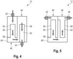
- the Figures 4 and 5 show a fourth and a fifth embodiment of the filter capsule 12, the design of which is more like a filter cassette or at least similar.
- the filter devices 46, 48 are not arranged one above the other in the common housing 40, but - based on their longitudinal direction - next to each other.
- the flow path in both embodiments is the same as in the second embodiment ( Figure 2 ), that is, from the outside area of the first filter device 46 into its core area 50 and from there via the outside area of the second filter device 48 into its core area 52.
- the inlet connection 42 is in direct flow connection with the outer area of the first filter device 46 and the outlet connection 44 with the core region 52 of the second filter device 48.
- the inlet connection 42 and the outlet connection 44 are arranged offset on opposite sides of the common housing 40, which lie opposite the front ends of the filter devices 46, 48.
- the fifth embodiment shown is the inlet connection 42 and the Drain connection 44 is not arranged offset at the upper end of housing sides, which run essentially parallel to the longitudinal directions of the filter devices 46, 48.
- the invention is not limited to the specifically shown and described embodiments of the filter capsule 12. Of course, individual aspects of the different embodiments can be combined with one another.
- filter capsule 12 What all embodiments of the filter capsule 12 have in common is that at least two filter devices 46, 48 are connected one behind the other, i.e. in series. In principle, more than two filter devices 46, 48 can also be provided within the housing 40.
- the flow directions through the individual filter devices 46, 48 result from the specific arrangement and design of the filter devices 46, 48. They can be the same for all filter devices 46, 48 or vary.
- an integrity test is carried out using a suitable testing device indirectly from the inlet connection 42, step by step through the individual filter devices 46, 48.
- the so-called bubble point is passed through within a measurement for each filter device 46, 48 and can be evaluated from the course of the measurement pressure.
- the diffusion measurement must - again from the inlet connection 42 - be controlled in stages with a separate test pressure for each filter device 46, 48, with the restriction that each diffusion test pressure must be above the bubble point pressure of the upstream filter device 46, 48.
- an integrity test measurement is carried out on each filter device 46, 48 individually, with the test device via the respective one Vent valve of the respective filter device 46, 48 is connected.
- This works according to today's common integrity testing procedure. The prerequisite is that the central entrance of the disposable filter capsule 12 is closed, so that pressure builds up and is tight in the upstream filter devices 46, 48. If necessary, the filter devices 46, 48 must also be connected to the test device via their vent valves in order to ensure pressure equalization.
- a preferred application of the filter capsule 12 is use in a disposable filtration device.
- a disposable filtration device 10 is shown, which is from the WO 2017/032560 A1 known device is similar.
- a plurality of filter capsules 12 can be held in position by a rigid holder 14 in a predetermined arrangement (grid).
- the holder 14 comprises at least two opposite side walls 16, which are connected to one another by cross struts 18, wherein the side walls 16 can have feet 26.
- Holding means 20 for the individual filter capsules 12 are provided on the cross struts 18.
- the filter capsules 12 are completely or at least largely connected to one another by rigid, pressure-stable pipes 22 with a defined diameter.
- the course of the pipes 22 is determined by the intended operation of the filtration device 10 (parallel or series connection or combination of parallel and series connection of the filter capsules 12), with the pipes 22 having the necessary branches 24 to the individual filter capsules 12.
- the pipelines 22 form either several line branches with associated filter capsules 12, through which the flow passes one after the other or in parallel, or at least two separate, independent line branches with associated filter capsules 12. If necessary, the pipelines 22 are attached to the holder 14.
- the filter capsules 12 are preconfigured for a desired filtration process, in particular with regard to filter type, design and/or size. The same applies to the arrangement and route as well as the connections of the pipes 22.
- the essential components of the rigid holder 14, the rigid housings of the filter capsules 12 and the rigid pipes 22 are all preferably made of the same material.
- This material and possibly other materials that are used in the device 10 can be sterilized, in particular using gamma radiation, and autoclaved after one-time use.
- the filtration device 10 can therefore be pre-assembled, i.e. H. packed and sterilized ready for connection.
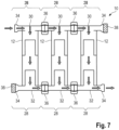
- FIG 7 A special embodiment of the disposable filtration device 10 is shown schematically without the holder 14.
- the disposable filtration device 10 is shown here with filter capsules 12, in which two separate filter devices are permanently installed one above the other in a housing 40.
- inlet and outlet units 28 made of sterilizable, in particular gamma sterilizable, plastic are provided here.
- a separate inlet and outlet unit 28 is provided with an inlet device 30 or an outlet device 32, which are coordinated with the front inlet and outlet connections of the respective filter capsule 12.
- the inlet device 30 and the outlet device 32 are either completely identical or at least largely identical. Both the inlet device 30 and the outlet device 32 each have two opposite external connections 34.
- suitable connecting components 36 such as TRI-clamp connections, several inlet and outlet units 28 can be connected to one another under controlled conditions. In this way, any number of filter capsules 12 can be put together.
- the external connections 34 that are not required are sealed by suitable closures 38 under controlled conditions.
- the inlet and outlet units 28 can be designed in one piece, as a kit or as a prefabricated unit.
- several inlet devices 30 and/or outlet devices 32 can be designed in one piece or pre-assembled before they are attached to the filter capsules 12.
- series connection covers enable the parallel flow of several filter capsules 12 and can be combined as desired with regard to the sizes and designs of the filter capsules 12. Overall, the series connection covers help the disposable filtration device 10 to have a more compact, smaller size, also because the holder 14 can be smaller. Since fewer components are required when using series connection covers, the disposable filtration device 10 is therefore more environmentally friendly overall.
- the filter capsules 12 can also be emptied centrally. At the lowest point of all or a group of filter capsules 12, a central collecting device can be arranged for their joint emptying.
- the respective filter capsules 12 should be held in an upright position by the holder 14.
- sensors for detecting certain process parameters and control devices for setting certain process parameters can be provided be.
- the sensors and control devices are connected to an external control and control system that is set up to evaluate and process sensor data and to control the control devices based on one or more control algorithms.
Landscapes
- Chemical & Material Sciences (AREA)
- Chemical Kinetics & Catalysis (AREA)
- Engineering & Computer Science (AREA)
- Water Supply & Treatment (AREA)
- External Artificial Organs (AREA)
- Separation Using Semi-Permeable Membranes (AREA)
Claims (11)
- Capsule filtrante jetable (12) pour un dispositif de filtration, comprenantun logement (40) qui présente un raccordement d'admission (42) pour un fluide à filtrer et un raccordement d'évacuation (44) pour filtrat, etau moins deux équipements filtrants,dans lequel les équipements filtrants (46, 48) sont montés en série,dans lequel toutes les composantes de la capsule filtrante jetable (12) sont composées de matériaux pouvant être stérilisés, en particulier pouvant être stérilisés aux rayons gamma,dans lequel les équipements filtrants (46, 48) sont conçus en tant que bougies filtrantes qui présentent respectivement une zone centrale (50, 52) creuse et entourée d'un milieu filtrant (54, 56) plissé et une zone extérieure qui est formée entre le milieu filtrant (54, 56) plissé et le logement (40), etdans lequel la capsule filtrante jetable (12) est une capsule filtrante pour liquide avec un matériau filtrant hydrophile,caractérisé en ce quele logement (40) est un logement extérieur unique et complet qui entoure toutes les composantes de la capsule filtrante jetable (12),dans lequel les équipements filtrants (46, 48) sont solidement installés dans le même logement (40) et forment avec celui-ci une unité de construction inséparable,dans lequel le raccordement d'admission (42) est en liaison d'écoulement directe avec la zone extérieure d'un premier équipement filtrant (46) et le raccordement d'évacuation (44) est en liaison d'écoulement directe avec la zone centrale (52) d'un deuxième équipement filtrant (48), etdans lequel les zones extérieures des équipements filtrants (46, 48) sont fluidiquement séparées l'une de l'autre par un barrage (58).
- Capsule filtrante jetable (12) selon la revendication 1, caractérisée en ce qu'au moins deux équipements filtrants (46, 48) séparés sont solidement installés dans le logement (40).
- Capsule filtrante jetable (12) selon la revendication 1 ou 2, caractérisée en ce que le raccordement d'admission (42) et le raccordement d'évacuation (44) sont prévus contre des extrémités frontales opposées du logement (40).
- Capsule filtrante jetable (12) selon la revendication 1 ou 2, caractérisée en ce que le raccordement d'admission (42) et le raccordement d'évacuation (44) sont prévus contre une paroi latérale du logement (40).
- Capsule filtrante jetable (12) selon l'une des revendications précédentes, caractérisée en ce que les équipements filtrants (46, 48) sont cylindriques et sont agencés dans la direction axiale les uns sur les autres ou parallèles les uns à côté des autres.
- Capsule filtrante jetable (12) selon l'une des revendications précédentes, caractérisée en ce que la zone centrale (50) du premier équipement filtrant (46) est en liaison d'écoulement directe avec la zone extérieure du deuxième équipement filtrant (48).
- Capsule filtrante jetable (12) selon l'une des revendications précédentes, caractérisée en ce que les équipements filtrants (46, 48) sont réalisés en tant que filtres stériles.
- Capsule filtrante jetable (12) selon l'une des revendications 1 à 6, caractérisée en ce que le premier équipement filtrant (46) est réalisé en tant que préfiltre et le deuxième équipement filtrant (48) est réalisé en tant que filtre stérile ou filtre viral.
- Capsule filtrante jetable (12) selon l'une des revendications précédentes, caractérisée en ce que les équipements filtrants (46, 48) se différencient en fonction d'au moins un paramètre caractéristique pour les équipements filtrants (46, 48).
- Capsule filtrante jetable (12) selon l'une des revendications précédentes, caractérisée en ce qu'au moins trois équipements filtrants (46, 48), de préférence au moins quatre équipements filtrants (46, 48), sont solidement installés dans le logement (40).
- Dispositif de filtration jetable (10) pouvant être entièrement préstérilisé, prêt à être raccordé et pouvant faire l'objet d'un test d'intégrité, caractérisé par au moins une, de préférence au moins deux, capsules filtrantes jetables (12) selon l'une des revendications précédentes, dans lequel de préférence un filtre à air central pour l'aération commune de toutes les ou d'un groupe de capsules filtrantes (12) et/ou de préférence un équipement collecteur central pour le vidage de toutes les ou d'un groupe de capsules filtrantes (12) est/sont prévu(s) et/ou de préférence plusieurs capsules filtrantes (12) sont reliées entre elles par des conduites rigides et solidement amenées dans une grille universellement prédéfinie par un support (14), dans lequel les capsules filtrantes (12), en particulier en fonction du type de filtration, du type de construction et/ou de l'encombrement, et/ou les liaisons des capsules filtrantes (12) sont préconfigurées pour un processus de filtration souhaité.
Priority Applications (1)
| Application Number | Priority Date | Filing Date | Title |
|---|---|---|---|
| EP23201752.5A EP4331711A1 (fr) | 2017-07-26 | 2018-07-18 | Capsule filtrante jetable pour dispositif de filtration |
Applications Claiming Priority (2)
| Application Number | Priority Date | Filing Date | Title |
|---|---|---|---|
| DE102017116923.7A DE102017116923A1 (de) | 2017-07-26 | 2017-07-26 | Einweg-Filtercapsule für eine Filtrationsvorrichtung |
| PCT/EP2018/069545 WO2019020467A1 (fr) | 2017-07-26 | 2018-07-18 | Capsule filtrante jetable pour dispositif de filtration |
Related Child Applications (1)
| Application Number | Title | Priority Date | Filing Date |
|---|---|---|---|
| EP23201752.5A Division EP4331711A1 (fr) | 2017-07-26 | 2018-07-18 | Capsule filtrante jetable pour dispositif de filtration |
Publications (2)
| Publication Number | Publication Date |
|---|---|
| EP3658260A1 EP3658260A1 (fr) | 2020-06-03 |
| EP3658260B1 true EP3658260B1 (fr) | 2023-10-25 |
Family
ID=62986101
Family Applications (2)
| Application Number | Title | Priority Date | Filing Date |
|---|---|---|---|
| EP23201752.5A Pending EP4331711A1 (fr) | 2017-07-26 | 2018-07-18 | Capsule filtrante jetable pour dispositif de filtration |
| EP18743763.7A Active EP3658260B1 (fr) | 2017-07-26 | 2018-07-18 | Capsule filtrante jetable pour dispositif de filtration |
Family Applications Before (1)
| Application Number | Title | Priority Date | Filing Date |
|---|---|---|---|
| EP23201752.5A Pending EP4331711A1 (fr) | 2017-07-26 | 2018-07-18 | Capsule filtrante jetable pour dispositif de filtration |
Country Status (4)
| Country | Link |
|---|---|
| US (2) | US12121863B2 (fr) |
| EP (2) | EP4331711A1 (fr) |
| DE (1) | DE102017116923A1 (fr) |
| WO (1) | WO2019020467A1 (fr) |
Families Citing this family (3)
| Publication number | Priority date | Publication date | Assignee | Title |
|---|---|---|---|---|
| KR20210132921A (ko) * | 2020-04-28 | 2021-11-05 | 주식회사 아모그린텍 | 중력식 정수장치용 필터모듈 및 이를 포함하는 중력식 정수장치 |
| EP4019935B1 (fr) * | 2020-12-23 | 2023-06-21 | Sartorius Stedim Biotech GmbH | Essai d'intégrité pour une capsule à double filtre |
| EP4448140A4 (fr) * | 2021-12-14 | 2025-10-08 | Entegris Inc | Unité filtre à liquide composée de filtres agencés verticalement, et son procédé de fonctionnement |
Family Cites Families (14)
| Publication number | Priority date | Publication date | Assignee | Title |
|---|---|---|---|---|
| GB189411090A (en) * | 1894-06-07 | 1895-04-06 | Charles Edouard Chamberland | Improvements connected with the Filtering of Water and other Liquids. |
| US4256474A (en) | 1978-11-20 | 1981-03-17 | Finite Filter Company, Inc. | Filter housing and filter assemblies utilizing the same |
| DE3422435A1 (de) * | 1984-06-16 | 1986-01-16 | B. Braun Melsungen Ag, 3508 Melsungen | Verfahren und vorrichtung zur selektiven abtrennung pathologischer und/oder toxischer spezies aus blut oder blutplasma unter verwendung von filterkerzen |
| GB9106481D0 (en) * | 1991-03-27 | 1991-05-15 | Pall Corp | Filters and filter units |
| US5328609A (en) * | 1992-11-16 | 1994-07-12 | Magnusson Jon H | Multi-stage radial flow filtration system |
| DE19848389C2 (de) | 1998-10-21 | 2002-06-06 | Sartorius Gmbh | Capsule zur Filtration von Fluiden |
| US6942797B1 (en) * | 1999-05-27 | 2005-09-13 | Nate International | Filtration using pressure vessel with multiple filtration channels |
| DE10239241A1 (de) | 2002-08-27 | 2004-03-11 | Sartorius Ag | Filterelement, insbesondere zur statischen bzw. dead-end-Filtration von Fluiden, sowie Filtervorrichtung |
| EP1592494B1 (fr) * | 2003-01-07 | 2009-06-24 | NxStage Medical, Inc. | Systeme de filtration discontinue destine a la preparation d'un liquide de remplacement sterile pour la therapie renale |
| US7125490B2 (en) * | 2003-05-29 | 2006-10-24 | Porex Corporation | Porous filter |
| US20050279695A1 (en) * | 2004-06-17 | 2005-12-22 | Millipore Corporation | Disposable integral filter unit |
| US20080257814A1 (en) * | 2007-04-23 | 2008-10-23 | Millipore Corporation | Filtration Cartridge |
| DE102012017972B4 (de) * | 2012-09-12 | 2017-06-22 | Sartorius Stedim Biotech Gmbh | Kombifilter |
| DE102015114004B4 (de) | 2015-08-24 | 2020-07-02 | Sartorius Stedim Biotech Gmbh | Einweg-Filtrationsvorrichtung |
-
2017
- 2017-07-26 DE DE102017116923.7A patent/DE102017116923A1/de active Pending
-
2018
- 2018-07-18 US US16/633,643 patent/US12121863B2/en active Active
- 2018-07-18 EP EP23201752.5A patent/EP4331711A1/fr active Pending
- 2018-07-18 WO PCT/EP2018/069545 patent/WO2019020467A1/fr not_active Ceased
- 2018-07-18 EP EP18743763.7A patent/EP3658260B1/fr active Active
-
2024
- 2024-09-12 US US18/882,894 patent/US20250001364A1/en active Pending
Also Published As
| Publication number | Publication date |
|---|---|
| EP4331711A1 (fr) | 2024-03-06 |
| US20250001364A1 (en) | 2025-01-02 |
| DE102017116923A1 (de) | 2019-01-31 |
| US20200164289A1 (en) | 2020-05-28 |
| WO2019020467A1 (fr) | 2019-01-31 |
| US12121863B2 (en) | 2024-10-22 |
| EP3658260A1 (fr) | 2020-06-03 |
Similar Documents
| Publication | Publication Date | Title |
|---|---|---|
| EP1144095B1 (fr) | Dispositif de concentration et/ou de purification de macromolecules en solution et procede de fabrication d'un tel dispositif | |
| EP3630334B1 (fr) | Dispositif de filtration à usage unique préconfiguré | |
| DE102011111457B4 (de) | Filtervorrichtung | |
| WO2004020072A1 (fr) | Element filtrant, en particulier pour le filtrage statique ou d'extremite de fluides, et dispositif filtrant | |
| EP3658260B1 (fr) | Capsule filtrante jetable pour dispositif de filtration | |
| DE2231868B2 (de) | Zelle zur Duchführung der umgekehrten Osmose | |
| EP0399309A2 (fr) | Elément filtrant tubulaire | |
| DE3805361A1 (de) | Integralfilter fuer fluide aus mehreren ineinander geschachtelten filterelementen mit unterschiedlichem rueckhaltevermoegen und gehaeuse dafuer | |
| WO2019101541A1 (fr) | Dispositif à usage unique pour la filtration d'un volume important de substance | |
| EP0907397B1 (fr) | Unite de filtration avec element filtre de type cartouche | |
| DE102019132699A1 (de) | Vorrichtung zur Filterung von Bestandteilen aus einem Fluid | |
| DE3816434A1 (de) | Filtermodul aus schichtenfilterelementen | |
| EP1926540B1 (fr) | Dispositif filtrant | |
| DE19848389C2 (de) | Capsule zur Filtration von Fluiden | |
| EP4019935B1 (fr) | Essai d'intégrité pour une capsule à double filtre | |
| DE3805299C2 (fr) | ||
| WO2009132864A1 (fr) | Module de filtration, dispositif de filtration et utilisation d’un module de filtration | |
| EP3810303B1 (fr) | Système de filtration pour processus biopharmaceutiques | |
| DE4438327C1 (de) | Filtersystem | |
| DE102011006543A1 (de) | Membranfitrationsmodul | |
| DE202006004529U1 (de) | Filtereinsatz mit Verschluss für zweite Filterkammer | |
| EP4115964B1 (fr) | Dispositif filtre | |
| DE102005021660A1 (de) | Filtervorrichtung und Filtermodul | |
| WO1997026974A1 (fr) | Filtre a disques | |
| DE102016209793A1 (de) | Filtermodul und Filtervorrichtung |
Legal Events
| Date | Code | Title | Description |
|---|---|---|---|
| STAA | Information on the status of an ep patent application or granted ep patent |
Free format text: STATUS: UNKNOWN |
|
| STAA | Information on the status of an ep patent application or granted ep patent |
Free format text: STATUS: THE INTERNATIONAL PUBLICATION HAS BEEN MADE |
|
| PUAI | Public reference made under article 153(3) epc to a published international application that has entered the european phase |
Free format text: ORIGINAL CODE: 0009012 |
|
| STAA | Information on the status of an ep patent application or granted ep patent |
Free format text: STATUS: REQUEST FOR EXAMINATION WAS MADE |
|
| 17P | Request for examination filed |
Effective date: 20200217 |
|
| AK | Designated contracting states |
Kind code of ref document: A1 Designated state(s): AL AT BE BG CH CY CZ DE DK EE ES FI FR GB GR HR HU IE IS IT LI LT LU LV MC MK MT NL NO PL PT RO RS SE SI SK SM TR |
|
| AX | Request for extension of the european patent |
Extension state: BA ME |
|
| DAV | Request for validation of the european patent (deleted) | ||
| DAX | Request for extension of the european patent (deleted) | ||
| STAA | Information on the status of an ep patent application or granted ep patent |
Free format text: STATUS: EXAMINATION IS IN PROGRESS |
|
| 17Q | First examination report despatched |
Effective date: 20210421 |
|
| GRAP | Despatch of communication of intention to grant a patent |
Free format text: ORIGINAL CODE: EPIDOSNIGR1 |
|
| STAA | Information on the status of an ep patent application or granted ep patent |
Free format text: STATUS: GRANT OF PATENT IS INTENDED |
|
| INTG | Intention to grant announced |
Effective date: 20230630 |
|
| GRAS | Grant fee paid |
Free format text: ORIGINAL CODE: EPIDOSNIGR3 |
|
| GRAA | (expected) grant |
Free format text: ORIGINAL CODE: 0009210 |
|
| STAA | Information on the status of an ep patent application or granted ep patent |
Free format text: STATUS: THE PATENT HAS BEEN GRANTED |
|
| GRAT | Correction requested after decision to grant or after decision to maintain patent in amended form |
Free format text: ORIGINAL CODE: EPIDOSNCDEC |
|
| P01 | Opt-out of the competence of the unified patent court (upc) registered |
Effective date: 20230905 |
|
| RIN1 | Information on inventor provided before grant (corrected) |
Inventor name: NIKOLOUDIS, PASCHALIS Inventor name: HANDT, SEBASTIAN Inventor name: LAUSCH, RALF Inventor name: LOEWE, THOMAS Inventor name: FRIESE, THOMAS |
|
| AK | Designated contracting states |
Kind code of ref document: B1 Designated state(s): AL AT BE BG CH CY CZ DE DK EE ES FI FR GB GR HR HU IE IS IT LI LT LU LV MC MK MT NL NO PL PT RO RS SE SI SK SM TR |
|
| REG | Reference to a national code |
Ref country code: GB Ref legal event code: FG4D Free format text: NOT ENGLISH |
|
| REG | Reference to a national code |
Ref country code: CH Ref legal event code: EP |
|
| REG | Reference to a national code |
Ref country code: DE Ref legal event code: R096 Ref document number: 502018013512 Country of ref document: DE |
|
| REG | Reference to a national code |
Ref country code: CH Ref legal event code: PK Free format text: BERICHTIGUNGEN |
|
| REG | Reference to a national code |
Ref country code: IE Ref legal event code: FG4D Free format text: LANGUAGE OF EP DOCUMENT: GERMAN |
|
| REG | Reference to a national code |
Ref country code: SE Ref legal event code: TRGR |
|
| RIN2 | Information on inventor provided after grant (corrected) |
Inventor name: LOEWE, THOMAS Inventor name: NIKOLOUDIS, PASCHALIS Inventor name: HANDT, SEBASTIAN Inventor name: LAUSCH, RALF Inventor name: FRIESE, THOMAS |
|
| REG | Reference to a national code |
Ref country code: LT Ref legal event code: MG9D |
|
| REG | Reference to a national code |
Ref country code: NL Ref legal event code: MP Effective date: 20231025 |
|
| PG25 | Lapsed in a contracting state [announced via postgrant information from national office to epo] |
Ref country code: NL Free format text: LAPSE BECAUSE OF FAILURE TO SUBMIT A TRANSLATION OF THE DESCRIPTION OR TO PAY THE FEE WITHIN THE PRESCRIBED TIME-LIMIT Effective date: 20231025 |
|
| PG25 | Lapsed in a contracting state [announced via postgrant information from national office to epo] |
Ref country code: GR Free format text: LAPSE BECAUSE OF FAILURE TO SUBMIT A TRANSLATION OF THE DESCRIPTION OR TO PAY THE FEE WITHIN THE PRESCRIBED TIME-LIMIT Effective date: 20240126 |
|
| PG25 | Lapsed in a contracting state [announced via postgrant information from national office to epo] |
Ref country code: IS Free format text: LAPSE BECAUSE OF FAILURE TO SUBMIT A TRANSLATION OF THE DESCRIPTION OR TO PAY THE FEE WITHIN THE PRESCRIBED TIME-LIMIT Effective date: 20240225 |
|
| PG25 | Lapsed in a contracting state [announced via postgrant information from national office to epo] |
Ref country code: LT Free format text: LAPSE BECAUSE OF FAILURE TO SUBMIT A TRANSLATION OF THE DESCRIPTION OR TO PAY THE FEE WITHIN THE PRESCRIBED TIME-LIMIT Effective date: 20231025 |
|
| PG25 | Lapsed in a contracting state [announced via postgrant information from national office to epo] |
Ref country code: ES Free format text: LAPSE BECAUSE OF FAILURE TO SUBMIT A TRANSLATION OF THE DESCRIPTION OR TO PAY THE FEE WITHIN THE PRESCRIBED TIME-LIMIT Effective date: 20231025 |
|
| PG25 | Lapsed in a contracting state [announced via postgrant information from national office to epo] |
Ref country code: LT Free format text: LAPSE BECAUSE OF FAILURE TO SUBMIT A TRANSLATION OF THE DESCRIPTION OR TO PAY THE FEE WITHIN THE PRESCRIBED TIME-LIMIT Effective date: 20231025 Ref country code: IS Free format text: LAPSE BECAUSE OF FAILURE TO SUBMIT A TRANSLATION OF THE DESCRIPTION OR TO PAY THE FEE WITHIN THE PRESCRIBED TIME-LIMIT Effective date: 20240225 Ref country code: GR Free format text: LAPSE BECAUSE OF FAILURE TO SUBMIT A TRANSLATION OF THE DESCRIPTION OR TO PAY THE FEE WITHIN THE PRESCRIBED TIME-LIMIT Effective date: 20240126 Ref country code: ES Free format text: LAPSE BECAUSE OF FAILURE TO SUBMIT A TRANSLATION OF THE DESCRIPTION OR TO PAY THE FEE WITHIN THE PRESCRIBED TIME-LIMIT Effective date: 20231025 Ref country code: BG Free format text: LAPSE BECAUSE OF FAILURE TO SUBMIT A TRANSLATION OF THE DESCRIPTION OR TO PAY THE FEE WITHIN THE PRESCRIBED TIME-LIMIT Effective date: 20240125 Ref country code: PT Free format text: LAPSE BECAUSE OF FAILURE TO SUBMIT A TRANSLATION OF THE DESCRIPTION OR TO PAY THE FEE WITHIN THE PRESCRIBED TIME-LIMIT Effective date: 20240226 |
|
| PG25 | Lapsed in a contracting state [announced via postgrant information from national office to epo] |
Ref country code: RS Free format text: LAPSE BECAUSE OF FAILURE TO SUBMIT A TRANSLATION OF THE DESCRIPTION OR TO PAY THE FEE WITHIN THE PRESCRIBED TIME-LIMIT Effective date: 20231025 Ref country code: PL Free format text: LAPSE BECAUSE OF FAILURE TO SUBMIT A TRANSLATION OF THE DESCRIPTION OR TO PAY THE FEE WITHIN THE PRESCRIBED TIME-LIMIT Effective date: 20231025 Ref country code: NO Free format text: LAPSE BECAUSE OF FAILURE TO SUBMIT A TRANSLATION OF THE DESCRIPTION OR TO PAY THE FEE WITHIN THE PRESCRIBED TIME-LIMIT Effective date: 20240125 Ref country code: LV Free format text: LAPSE BECAUSE OF FAILURE TO SUBMIT A TRANSLATION OF THE DESCRIPTION OR TO PAY THE FEE WITHIN THE PRESCRIBED TIME-LIMIT Effective date: 20231025 Ref country code: HR Free format text: LAPSE BECAUSE OF FAILURE TO SUBMIT A TRANSLATION OF THE DESCRIPTION OR TO PAY THE FEE WITHIN THE PRESCRIBED TIME-LIMIT Effective date: 20231025 |
|
| PG25 | Lapsed in a contracting state [announced via postgrant information from national office to epo] |
Ref country code: DK Free format text: LAPSE BECAUSE OF FAILURE TO SUBMIT A TRANSLATION OF THE DESCRIPTION OR TO PAY THE FEE WITHIN THE PRESCRIBED TIME-LIMIT Effective date: 20231025 |
|
| PG25 | Lapsed in a contracting state [announced via postgrant information from national office to epo] |
Ref country code: CZ Free format text: LAPSE BECAUSE OF FAILURE TO SUBMIT A TRANSLATION OF THE DESCRIPTION OR TO PAY THE FEE WITHIN THE PRESCRIBED TIME-LIMIT Effective date: 20231025 |
|
| REG | Reference to a national code |
Ref country code: DE Ref legal event code: R097 Ref document number: 502018013512 Country of ref document: DE |
|
| PG25 | Lapsed in a contracting state [announced via postgrant information from national office to epo] |
Ref country code: SK Free format text: LAPSE BECAUSE OF FAILURE TO SUBMIT A TRANSLATION OF THE DESCRIPTION OR TO PAY THE FEE WITHIN THE PRESCRIBED TIME-LIMIT Effective date: 20231025 |
|
| PG25 | Lapsed in a contracting state [announced via postgrant information from national office to epo] |
Ref country code: SM Free format text: LAPSE BECAUSE OF FAILURE TO SUBMIT A TRANSLATION OF THE DESCRIPTION OR TO PAY THE FEE WITHIN THE PRESCRIBED TIME-LIMIT Effective date: 20231025 Ref country code: SK Free format text: LAPSE BECAUSE OF FAILURE TO SUBMIT A TRANSLATION OF THE DESCRIPTION OR TO PAY THE FEE WITHIN THE PRESCRIBED TIME-LIMIT Effective date: 20231025 Ref country code: RO Free format text: LAPSE BECAUSE OF FAILURE TO SUBMIT A TRANSLATION OF THE DESCRIPTION OR TO PAY THE FEE WITHIN THE PRESCRIBED TIME-LIMIT Effective date: 20231025 Ref country code: IT Free format text: LAPSE BECAUSE OF FAILURE TO SUBMIT A TRANSLATION OF THE DESCRIPTION OR TO PAY THE FEE WITHIN THE PRESCRIBED TIME-LIMIT Effective date: 20231025 Ref country code: EE Free format text: LAPSE BECAUSE OF FAILURE TO SUBMIT A TRANSLATION OF THE DESCRIPTION OR TO PAY THE FEE WITHIN THE PRESCRIBED TIME-LIMIT Effective date: 20231025 Ref country code: DK Free format text: LAPSE BECAUSE OF FAILURE TO SUBMIT A TRANSLATION OF THE DESCRIPTION OR TO PAY THE FEE WITHIN THE PRESCRIBED TIME-LIMIT Effective date: 20231025 Ref country code: CZ Free format text: LAPSE BECAUSE OF FAILURE TO SUBMIT A TRANSLATION OF THE DESCRIPTION OR TO PAY THE FEE WITHIN THE PRESCRIBED TIME-LIMIT Effective date: 20231025 |
|
| PLBE | No opposition filed within time limit |
Free format text: ORIGINAL CODE: 0009261 |
|
| STAA | Information on the status of an ep patent application or granted ep patent |
Free format text: STATUS: NO OPPOSITION FILED WITHIN TIME LIMIT |
|
| 26N | No opposition filed |
Effective date: 20240726 |
|
| PG25 | Lapsed in a contracting state [announced via postgrant information from national office to epo] |
Ref country code: SI Free format text: LAPSE BECAUSE OF FAILURE TO SUBMIT A TRANSLATION OF THE DESCRIPTION OR TO PAY THE FEE WITHIN THE PRESCRIBED TIME-LIMIT Effective date: 20231025 |
|
| PG25 | Lapsed in a contracting state [announced via postgrant information from national office to epo] |
Ref country code: SI Free format text: LAPSE BECAUSE OF FAILURE TO SUBMIT A TRANSLATION OF THE DESCRIPTION OR TO PAY THE FEE WITHIN THE PRESCRIBED TIME-LIMIT Effective date: 20231025 |
|
| PG25 | Lapsed in a contracting state [announced via postgrant information from national office to epo] |
Ref country code: MC Free format text: LAPSE BECAUSE OF FAILURE TO SUBMIT A TRANSLATION OF THE DESCRIPTION OR TO PAY THE FEE WITHIN THE PRESCRIBED TIME-LIMIT Effective date: 20231025 |
|
| PG25 | Lapsed in a contracting state [announced via postgrant information from national office to epo] |
Ref country code: LU Free format text: LAPSE BECAUSE OF NON-PAYMENT OF DUE FEES Effective date: 20240718 |
|
| PG25 | Lapsed in a contracting state [announced via postgrant information from national office to epo] |
Ref country code: LU Free format text: LAPSE BECAUSE OF NON-PAYMENT OF DUE FEES Effective date: 20240718 |
|
| PG25 | Lapsed in a contracting state [announced via postgrant information from national office to epo] |
Ref country code: BE Free format text: LAPSE BECAUSE OF NON-PAYMENT OF DUE FEES Effective date: 20240731 |
|
| REG | Reference to a national code |
Ref country code: BE Ref legal event code: MM Effective date: 20240731 |
|
| PG25 | Lapsed in a contracting state [announced via postgrant information from national office to epo] |
Ref country code: IE Free format text: LAPSE BECAUSE OF NON-PAYMENT OF DUE FEES Effective date: 20240718 |
|
| REG | Reference to a national code |
Ref country code: AT Ref legal event code: MM01 Ref document number: 1624120 Country of ref document: AT Kind code of ref document: T Effective date: 20240718 |
|
| PG25 | Lapsed in a contracting state [announced via postgrant information from national office to epo] |
Ref country code: FI Free format text: LAPSE BECAUSE OF FAILURE TO SUBMIT A TRANSLATION OF THE DESCRIPTION OR TO PAY THE FEE WITHIN THE PRESCRIBED TIME-LIMIT Effective date: 20231025 |
|
| PGFP | Annual fee paid to national office [announced via postgrant information from national office to epo] |
Ref country code: DE Payment date: 20250722 Year of fee payment: 8 |
|
| PGFP | Annual fee paid to national office [announced via postgrant information from national office to epo] |
Ref country code: GB Payment date: 20250724 Year of fee payment: 8 |
|
| PG25 | Lapsed in a contracting state [announced via postgrant information from national office to epo] |
Ref country code: AT Free format text: LAPSE BECAUSE OF NON-PAYMENT OF DUE FEES Effective date: 20240718 |
|
| PGFP | Annual fee paid to national office [announced via postgrant information from national office to epo] |
Ref country code: FR Payment date: 20250723 Year of fee payment: 8 |
|
| PGFP | Annual fee paid to national office [announced via postgrant information from national office to epo] |
Ref country code: CH Payment date: 20250801 Year of fee payment: 8 Ref country code: SE Payment date: 20250723 Year of fee payment: 8 |
|
| PG25 | Lapsed in a contracting state [announced via postgrant information from national office to epo] |
Ref country code: CY Free format text: LAPSE BECAUSE OF FAILURE TO SUBMIT A TRANSLATION OF THE DESCRIPTION OR TO PAY THE FEE WITHIN THE PRESCRIBED TIME-LIMIT; INVALID AB INITIO Effective date: 20180718 |
|
| PG25 | Lapsed in a contracting state [announced via postgrant information from national office to epo] |
Ref country code: HU Free format text: LAPSE BECAUSE OF FAILURE TO SUBMIT A TRANSLATION OF THE DESCRIPTION OR TO PAY THE FEE WITHIN THE PRESCRIBED TIME-LIMIT; INVALID AB INITIO Effective date: 20180718 |