EP3658397B1 - Ensemble d'entraînement électrique d'un essieu pour un véhicule automobile, et véhicule utilitaire associé - Google Patents
Ensemble d'entraînement électrique d'un essieu pour un véhicule automobile, et véhicule utilitaire associé Download PDFInfo
- Publication number
- EP3658397B1 EP3658397B1 EP18738212.2A EP18738212A EP3658397B1 EP 3658397 B1 EP3658397 B1 EP 3658397B1 EP 18738212 A EP18738212 A EP 18738212A EP 3658397 B1 EP3658397 B1 EP 3658397B1
- Authority
- EP
- European Patent Office
- Prior art keywords
- spur gear
- electric machine
- stage
- gear stage
- vehicle
- Prior art date
- Legal status (The legal status is an assumption and is not a legal conclusion. Google has not performed a legal analysis and makes no representation as to the accuracy of the status listed.)
- Active
Links
Images


Classifications
-
- B—PERFORMING OPERATIONS; TRANSPORTING
- B60—VEHICLES IN GENERAL
- B60K—ARRANGEMENT OR MOUNTING OF PROPULSION UNITS OR OF TRANSMISSIONS IN VEHICLES; ARRANGEMENT OR MOUNTING OF PLURAL DIVERSE PRIME-MOVERS IN VEHICLES; AUXILIARY DRIVES FOR VEHICLES; INSTRUMENTATION OR DASHBOARDS FOR VEHICLES; ARRANGEMENTS IN CONNECTION WITH COOLING, AIR INTAKE, GAS EXHAUST OR FUEL SUPPLY OF PROPULSION UNITS IN VEHICLES
- B60K1/00—Arrangement or mounting of electrical propulsion units
-
- B—PERFORMING OPERATIONS; TRANSPORTING
- B60—VEHICLES IN GENERAL
- B60K—ARRANGEMENT OR MOUNTING OF PROPULSION UNITS OR OF TRANSMISSIONS IN VEHICLES; ARRANGEMENT OR MOUNTING OF PLURAL DIVERSE PRIME-MOVERS IN VEHICLES; AUXILIARY DRIVES FOR VEHICLES; INSTRUMENTATION OR DASHBOARDS FOR VEHICLES; ARRANGEMENTS IN CONNECTION WITH COOLING, AIR INTAKE, GAS EXHAUST OR FUEL SUPPLY OF PROPULSION UNITS IN VEHICLES
- B60K17/00—Arrangement or mounting of transmissions in vehicles
- B60K17/04—Arrangement or mounting of transmissions in vehicles characterised by arrangement, location or kind of gearing
- B60K17/06—Arrangement or mounting of transmissions in vehicles characterised by arrangement, location or kind of gearing of change-speed gearing
- B60K17/08—Arrangement or mounting of transmissions in vehicles characterised by arrangement, location or kind of gearing of change-speed gearing of mechanical type
-
- B—PERFORMING OPERATIONS; TRANSPORTING
- B60—VEHICLES IN GENERAL
- B60K—ARRANGEMENT OR MOUNTING OF PROPULSION UNITS OR OF TRANSMISSIONS IN VEHICLES; ARRANGEMENT OR MOUNTING OF PLURAL DIVERSE PRIME-MOVERS IN VEHICLES; AUXILIARY DRIVES FOR VEHICLES; INSTRUMENTATION OR DASHBOARDS FOR VEHICLES; ARRANGEMENTS IN CONNECTION WITH COOLING, AIR INTAKE, GAS EXHAUST OR FUEL SUPPLY OF PROPULSION UNITS IN VEHICLES
- B60K17/00—Arrangement or mounting of transmissions in vehicles
- B60K17/04—Arrangement or mounting of transmissions in vehicles characterised by arrangement, location or kind of gearing
- B60K17/12—Arrangement or mounting of transmissions in vehicles characterised by arrangement, location or kind of gearing of electric gearing
-
- B—PERFORMING OPERATIONS; TRANSPORTING
- B60—VEHICLES IN GENERAL
- B60K—ARRANGEMENT OR MOUNTING OF PROPULSION UNITS OR OF TRANSMISSIONS IN VEHICLES; ARRANGEMENT OR MOUNTING OF PLURAL DIVERSE PRIME-MOVERS IN VEHICLES; AUXILIARY DRIVES FOR VEHICLES; INSTRUMENTATION OR DASHBOARDS FOR VEHICLES; ARRANGEMENTS IN CONNECTION WITH COOLING, AIR INTAKE, GAS EXHAUST OR FUEL SUPPLY OF PROPULSION UNITS IN VEHICLES
- B60K17/00—Arrangement or mounting of transmissions in vehicles
- B60K17/04—Arrangement or mounting of transmissions in vehicles characterised by arrangement, location or kind of gearing
- B60K17/16—Arrangement or mounting of transmissions in vehicles characterised by arrangement, location or kind of gearing of differential gearing
-
- B—PERFORMING OPERATIONS; TRANSPORTING
- B60—VEHICLES IN GENERAL
- B60K—ARRANGEMENT OR MOUNTING OF PROPULSION UNITS OR OF TRANSMISSIONS IN VEHICLES; ARRANGEMENT OR MOUNTING OF PLURAL DIVERSE PRIME-MOVERS IN VEHICLES; AUXILIARY DRIVES FOR VEHICLES; INSTRUMENTATION OR DASHBOARDS FOR VEHICLES; ARRANGEMENTS IN CONNECTION WITH COOLING, AIR INTAKE, GAS EXHAUST OR FUEL SUPPLY OF PROPULSION UNITS IN VEHICLES
- B60K17/00—Arrangement or mounting of transmissions in vehicles
- B60K17/04—Arrangement or mounting of transmissions in vehicles characterised by arrangement, location or kind of gearing
- B60K17/16—Arrangement or mounting of transmissions in vehicles characterised by arrangement, location or kind of gearing of differential gearing
- B60K17/20—Arrangement or mounting of transmissions in vehicles characterised by arrangement, location or kind of gearing of differential gearing in which the differential movement is limited
-
- B—PERFORMING OPERATIONS; TRANSPORTING
- B60—VEHICLES IN GENERAL
- B60K—ARRANGEMENT OR MOUNTING OF PROPULSION UNITS OR OF TRANSMISSIONS IN VEHICLES; ARRANGEMENT OR MOUNTING OF PLURAL DIVERSE PRIME-MOVERS IN VEHICLES; AUXILIARY DRIVES FOR VEHICLES; INSTRUMENTATION OR DASHBOARDS FOR VEHICLES; ARRANGEMENTS IN CONNECTION WITH COOLING, AIR INTAKE, GAS EXHAUST OR FUEL SUPPLY OF PROPULSION UNITS IN VEHICLES
- B60K23/00—Arrangement or mounting of control devices for vehicle transmissions, or parts thereof, not otherwise provided for
- B60K23/04—Arrangement or mounting of control devices for vehicle transmissions, or parts thereof, not otherwise provided for for differential gearing
-
- F—MECHANICAL ENGINEERING; LIGHTING; HEATING; WEAPONS; BLASTING
- F16—ENGINEERING ELEMENTS AND UNITS; GENERAL MEASURES FOR PRODUCING AND MAINTAINING EFFECTIVE FUNCTIONING OF MACHINES OR INSTALLATIONS; THERMAL INSULATION IN GENERAL
- F16H—GEARING
- F16H3/00—Toothed gearings for conveying rotary motion with variable gear ratio or for reversing rotary motion
- F16H3/44—Toothed gearings for conveying rotary motion with variable gear ratio or for reversing rotary motion using gears having orbital motion
- F16H3/46—Gearings having only two central gears, connected by orbital gears
-
- F—MECHANICAL ENGINEERING; LIGHTING; HEATING; WEAPONS; BLASTING
- F16—ENGINEERING ELEMENTS AND UNITS; GENERAL MEASURES FOR PRODUCING AND MAINTAINING EFFECTIVE FUNCTIONING OF MACHINES OR INSTALLATIONS; THERMAL INSULATION IN GENERAL
- F16H—GEARING
- F16H48/00—Differential gearings
- F16H48/06—Differential gearings with gears having orbital motion
- F16H48/08—Differential gearings with gears having orbital motion comprising bevel gears
-
- F—MECHANICAL ENGINEERING; LIGHTING; HEATING; WEAPONS; BLASTING
- F16—ENGINEERING ELEMENTS AND UNITS; GENERAL MEASURES FOR PRODUCING AND MAINTAINING EFFECTIVE FUNCTIONING OF MACHINES OR INSTALLATIONS; THERMAL INSULATION IN GENERAL
- F16H—GEARING
- F16H48/00—Differential gearings
- F16H48/20—Arrangements for suppressing or influencing the differential action, e.g. locking devices
-
- B—PERFORMING OPERATIONS; TRANSPORTING
- B60—VEHICLES IN GENERAL
- B60K—ARRANGEMENT OR MOUNTING OF PROPULSION UNITS OR OF TRANSMISSIONS IN VEHICLES; ARRANGEMENT OR MOUNTING OF PLURAL DIVERSE PRIME-MOVERS IN VEHICLES; AUXILIARY DRIVES FOR VEHICLES; INSTRUMENTATION OR DASHBOARDS FOR VEHICLES; ARRANGEMENTS IN CONNECTION WITH COOLING, AIR INTAKE, GAS EXHAUST OR FUEL SUPPLY OF PROPULSION UNITS IN VEHICLES
- B60K1/00—Arrangement or mounting of electrical propulsion units
- B60K1/02—Arrangement or mounting of electrical propulsion units comprising more than one electric motor
-
- B—PERFORMING OPERATIONS; TRANSPORTING
- B60—VEHICLES IN GENERAL
- B60K—ARRANGEMENT OR MOUNTING OF PROPULSION UNITS OR OF TRANSMISSIONS IN VEHICLES; ARRANGEMENT OR MOUNTING OF PLURAL DIVERSE PRIME-MOVERS IN VEHICLES; AUXILIARY DRIVES FOR VEHICLES; INSTRUMENTATION OR DASHBOARDS FOR VEHICLES; ARRANGEMENTS IN CONNECTION WITH COOLING, AIR INTAKE, GAS EXHAUST OR FUEL SUPPLY OF PROPULSION UNITS IN VEHICLES
- B60K1/00—Arrangement or mounting of electrical propulsion units
- B60K2001/001—Arrangement or mounting of electrical propulsion units one motor mounted on a propulsion axle for rotating right and left wheels of this axle
-
- B—PERFORMING OPERATIONS; TRANSPORTING
- B60—VEHICLES IN GENERAL
- B60K—ARRANGEMENT OR MOUNTING OF PROPULSION UNITS OR OF TRANSMISSIONS IN VEHICLES; ARRANGEMENT OR MOUNTING OF PLURAL DIVERSE PRIME-MOVERS IN VEHICLES; AUXILIARY DRIVES FOR VEHICLES; INSTRUMENTATION OR DASHBOARDS FOR VEHICLES; ARRANGEMENTS IN CONNECTION WITH COOLING, AIR INTAKE, GAS EXHAUST OR FUEL SUPPLY OF PROPULSION UNITS IN VEHICLES
- B60K23/00—Arrangement or mounting of control devices for vehicle transmissions, or parts thereof, not otherwise provided for
- B60K23/04—Arrangement or mounting of control devices for vehicle transmissions, or parts thereof, not otherwise provided for for differential gearing
- B60K2023/046—Axle differential locking means
-
- B—PERFORMING OPERATIONS; TRANSPORTING
- B60—VEHICLES IN GENERAL
- B60Y—INDEXING SCHEME RELATING TO ASPECTS CROSS-CUTTING VEHICLE TECHNOLOGY
- B60Y2200/00—Type of vehicle
- B60Y2200/10—Road Vehicles
- B60Y2200/14—Trucks; Load vehicles, Busses
-
- B—PERFORMING OPERATIONS; TRANSPORTING
- B60—VEHICLES IN GENERAL
- B60Y—INDEXING SCHEME RELATING TO ASPECTS CROSS-CUTTING VEHICLE TECHNOLOGY
- B60Y2400/00—Special features of vehicle units
- B60Y2400/70—Gearings
- B60Y2400/73—Planetary gearings
Definitions
- the invention relates to an electric axle drive device for a motor vehicle according to the preamble of claim 1, an electric axle drive device for a motor vehicle according to the preamble of claim 13 and a motor vehicle with such an electric axle drive device.
- An electric axle drive device for a motor vehicle is, for example, the DE 10 2009 033 531 A1 , the US 9 453 564 B1 and the WO 2017/108168 A1 as known.
- the electric axle drive device has at least one drive wheel of the motor vehicle rotatable about a wheel axis of rotation and at least one electric machine with a stator and with a rotor.
- the rotor is rotatable about a machine axis of rotation relative to the stator, the machine axis of rotation running parallel to the wheel axis of rotation.
- the electric axle drive device furthermore has a transmission which can be driven by the first electrical machine and which has at least one first planetary gear stage and at least one first spur gear stage which can be driven by the first electrical machine.
- the spur gear stage in turn has a first spur gear and a second spur gear meshing with the first spur gear, which can be driven by the first electrical machine, for example, via the first spur gear and via the first planetary gear stage.
- the drive wheel the wheel axis of rotation of which runs parallel to the machine axis of rotation, can be driven by the first electrical machine via the transmission, so that, for example, the motor vehicle as a whole can be electrically driven by the electrical machine.
- an electric axle drive device in which an electric machine with respect to a vehicle vertical direction and a longitudinal center plane of a motor vehicle spanned in the longitudinal direction of the vehicle is arranged at least partially on a first side of the longitudinal center plane; and a spur gear stage is arranged on a second side of the longitudinal center plane (66) opposite the first side in the vehicle transverse direction.
- Something similar is at least hinted at from the scriptures DE 10 2015 208 825 A1 and DE 10 2017 104 674 A1 (post-published) known.
- a hybrid drive train is also known in which a plurality of planetary gear stages and two spur gear stages are arranged between an electrical machine and an axle drive.
- the object of the present invention is to further develop an electric axle drive device and a motor vehicle of the type mentioned at the beginning in such a way that particularly advantageous operation and, at the same time, a particularly compact design of the electric axle drive device can be implemented.
- the electric axle drive device has an axle drive which can be driven by the electric machine via the transmission and via which the drive wheel can be driven by the first electric machine.
- This enables particularly advantageous operation to be implemented, since the at least one drive wheel can be driven by the electric machine in a particularly advantageous manner, in particular with a particularly advantageous gear ratio.
- the at least one drive wheel and at least one second drive wheel via the axle drive and the To drive the transmission from the electric machine, the previous and following statements on the at least one drive wheel can be easily transferred to the at least one second drive wheel and vice versa.
- the drive wheels are assigned to an axle, in particular a rear axle or a front axle, so that the axle or the drive wheels of the axle can be driven particularly advantageously by means of the electric machine, in particular via the axle drive and the gearbox.
- the axle drive is preferably designed as a differential or differential gear, in particular as a bevel gear differential, so that particularly advantageous operation can be implemented.
- the differential gear allows, for example, speed differences or a speed compensation between the drive wheels, especially when cornering, so that the drive wheel on the outside of the curve can rotate at a higher speed than the drive wheel on the inside of the curve without causing a Excessive tension of the final drive device occurs. This enables particularly advantageous operation to be implemented.
- the first electric machine - in particular with regard to an installation position of the electric axle drive device - is in terms of a longitudinal center plane spanned by the vertical direction of the vehicle and the longitudinal direction of the vehicle Motor vehicle arranged at least partially on a first side of the longitudinal center plane, the first spur gear stage being arranged on a second side of the longitudinal center plane opposite the first side in the transverse direction of the vehicle.
- the electric axle drive device assumes its installation position in the fully manufactured state of the motor vehicle, the electric axle drive device being held in the fully manufactured state of the motor vehicle on the motor vehicle, in particular at least indirectly on a body or on a frame of the motor vehicle.
- the fully manufactured state of the motor vehicle it stands, for example, on a horizontal plane, so that the longitudinal center plane is a vertical longitudinal center plane which, in the fully manufactured state of the motor vehicle, runs at least substantially perpendicular to the transverse direction of the vehicle, to the horizontal or to the horizontal plane.
- the longitudinal center plane is thus also referred to as the vertical longitudinal center plane or the vertical longitudinal vehicle center plane.
- the longitudinal center plane can be understood to mean the following:
- the motor vehicle, in particular the electric axle drive device, in its or its fully manufactured state has a width running in the transverse direction of the vehicle, in particular in relation to the installation position, the center of this width lying in the longitudinal center plane, for example.
- the motor vehicle or the electric axle drive device Starting from the center or starting from the longitudinal center plane, the motor vehicle or the electric axle drive device extends in the vehicle transverse direction by a first distance to the left outside and in the vehicle transverse direction by a second distance to the right outside, the first distance corresponding to the second distance or vice versa, that is, where the distances are the same.
- the motor vehicle or the electric axle drive device is not necessarily designed symmetrically with respect to the longitudinal center plane, so that the longitudinal center plane is not necessarily a plane of symmetry of the motor vehicle or the electric axle drive device.
- the transmission has a second planetary gear stage, as a result of which a particularly advantageous transmission ratio of the transmission as a whole can be created in a manner that is economical in terms of space and weight.
- the at least one drive wheel or the drive wheels can be driven particularly advantageously, so that particularly advantageous operation can be implemented.
- the transmission has exactly two planetary gear stages and exactly two spur gear stages.
- the first planetary gear stage after the electrical machine and before the drive wheel the first spur gear stage after the first planetary gear stage and before the drive wheel
- the respective planetary gear stage has, for example, a sun gear as the first gear element, a ring gear as the second gear element and at least one planet carrier as the third gear element. Furthermore, the respective planetary gear stage has at least one planetary gear which, for example, meshes with the respective sun gear and with the respective ring gear and is rotatably held on the planet carrier.
- At least one of the gear elements of the second planetary gear stage can thus be fixed to the housing of the gear, it being possible for the gear elements of the second planetary gear stage to be accommodated in said housing.
- the braking element can, for example, be switched, in particular moved, between at least one braking state or between at least one braking position and at least one release state or one release position.
- the respective gear elements of the respective planetary gear stage, in particular the second planetary gear stage can for example be rotated about a common main axis of rotation relative to the housing, in particular when the braking element is in the release state or in the release position and when, for example, the second planetary gear stage is being driven.
- the brake element in its release state or in its release position, allows a rotation of one gear element of the second planetary gear stage about the main axis of rotation relative to the housing, so that at least one gear element of the second planetary gear stage is rotated about the main axis of rotation relative to the housing when the second planetary gear stage is driven.
- the braking element if the braking element is in its braking position or in its braking state, one gear element of the second planetary gear stage is fixed to the housing by means of the braking element, in particular non-rotatably, so that the one gear element of the second planetary gear stage does not move relative to the main axis of rotation the housing rotates when the second planetary gear stage is driven, that is, when torques are introduced into the second planetary gear stage.
- the braking element thus makes it possible to use the one transmission element of the second planetary gear stage as required on the housing, in particular non-rotatably, to be fixed and released, so that switchability of the second planetary gear stage is implemented or can be implemented.
- the second planetary gear stage is designed as a switchable planetary set, so that, for example, at least two different ratios can be represented, via which the at least one drive wheel can be driven by the electrical machine.
- the gear ratios can be switched in that the braking element can be switched or moved between the release state and the braking state.
- a neutral position or a neutral state can be represented as idling.
- the invention further provides that the braking element has the ring gear of the second planetary gear stage or is designed as the ring gear of the second planetary gear stage, the ring gear of the second planetary gear stage in the axial direction of the second planetary gear stage relative to the Housing is displaceable to thereby move the braking element between the release position and the braking position.
- the axial direction of the second planetary gear stage coincides, for example, with the main axis of rotation of the second planetary gear stage.
- the ring gear has a double function, since it is used on the one hand to implement at least one advantageous gear ratio and on the other hand as the braking element described.
- the entirety of the invention ensures that both a high-performance electric axle drive device is represented and an electric axle drive device that, based on a classic non-electrified axle drive device, leads to a very compact unit despite extreme structural restrictions.
- At least one locking element is provided, by means of which at least two of the gear elements of the second planetary gear stage can be interlocked with one another.
- the blocking element can, for example, be switched, in particular moved, between at least one blocking state or at least one blocking position and at least one release state or at least one release position.
- the two are in the locked state or in the locked position by means of the locking element
- Gear elements of the second planetary gear stage are interlocked, that is, connected to one another in a rotationally fixed manner, so that the second gear elements of the second planetary gear stage rotate as a block, that is, together around the main axis of rotation, in particular when the second planetary gear stage is driven.
- the two gear elements rotate together about the main axis of rotation relative to the housing when the second planetary gear stage is driven.
- the locking element releases the second gear element of the second planetary gear stage, in particular for relative rotation to one another about the main axis of rotation, so that the second gear element, in particular when the second planetary gear stage is driven, revolves around the main axis of rotation relative to one another and can rotate relative to the housing.
- the above-mentioned, mutually different ratios can be represented in a particularly space-saving and weight-saving manner, since the second planetary gear stage is or can be designed as a switchable planetary gear stage or as a switchable planetary set by using the locking element.
- the second planetary gear stage is arranged at least partially, in particular at least predominantly or completely, on the second side of the longitudinal center plane.
- the second spur gear stage is arranged at least essentially in or on the longitudinal center plane.
- the longitudinal center plane extends through respective, intermeshing spur gears of the second spur gear stage so that, for example, the spur gears of the second spur gear stage are arranged at least essentially in the center of the axle drive device or said axis with respect to the transverse direction of the vehicle.
- the electric machine is arranged at least two thirds of its, in particular outer, volume or its outer dimensions on the first side of the longitudinal center plane.
- Another embodiment is characterized in that a second electrical machine and a further spur gear that can be driven by the second electrical machine and mesh with the second spur gear are provided.
- the second electrical machine can thus provide torques as drive torques, which are transmitted, for example, via the further spur gear to the second spur gear of the first spur gear transmission stage and can thus be introduced into the transmission.
- the second electrical machine is thus coupled via the further spur gear to the second spur gear of the first spur gear stage, the respective spur gear stage also being referred to as a spur gear stage.
- the respective planetary gear stage is also referred to as a planetary stage, planetary set or planetary gear set.
- the at least one drive wheel can be driven by means of the two electrical machines, since the respective electrical machine can provide at least one respective torque as a drive torque for driving the at least one drive wheel.
- the first electrical machine can, for example, provide its drive torque via the first spur gear of the first spur gear stage, wherein the second electrical machine can provide its drive torque via the further spur gear.
- the respective drive torques provided by the respective electrical machines are transmitted to the second spur gear of the first spur gear stage and combined on the second spur gear, so that a particularly advantageous and compact drive can be produced.
- the second electrical machine is aligned with the first electrical machine along a direction perpendicular to the transverse direction of the vehicle and thus, for example, at least substantially parallel to the longitudinal center plane.
- the second electrical machine has, for example, a second stator and a second rotor which is rotatable about a second machine axis of rotation relative to the second stator. It is preferably provided that the second machine axis of rotation is offset from the first machine axis of rotation, the respective machine axis of rotation preferably being offset from the wheel axis of rotation.
- the machine axes of rotation lie in a common plane which, for example, runs parallel to the vertical direction of the vehicle or parallel to the longitudinal center plane or coincides with the longitudinal center plane.
- the wheel rotation axes and the respective machine axis of rotation preferably run at least substantially in the transverse direction of the vehicle.
- Another embodiment is characterized in that the first planetary gear stage, the first electrical machine and the first spur gear stage are arranged in a common housing, in particular in the aforementioned housing, the housing being in equal parts on the first side and on the second side of the longitudinal center plane is arranged.
- This allows a compact design to be achieved.
- the first planetary gear stage, the first electrical machine and the first spur gear stage as well as the housing common to them form a module which can be handled and installed easily and inexpensively.
- an oil cooler and / or power electronics are or is arranged on a side of the first electrical machine facing away from the axle drive or on a side of the axle drive facing away from the first electrical machine .
- the second electric machine is arranged on a third side of the further level with regard to a further plane of the motor vehicle spanned by the transverse direction of the vehicle and the longitudinal direction of the vehicle, with the first electric machine on a third side opposite the fourth side in the vertical direction of the vehicle the further level is arranged.
- the electrical machines are arranged one above the other in the vertical direction of the vehicle, for example one of the electrical machines in the vertical direction of the vehicle is at least partially, in particular at least predominantly or completely, covered by the other electrical machine or so that, for example, the other electrical machine is at least downward in the vertical direction of the vehicle is partially, in particular at least predominantly or completely, covered by an electrical machine.
- the invention also includes a motor vehicle, in particular a utility vehicle, with at least one electrical axle drive device according to the invention.
- Advantages and advantageous refinements of the axle drive device according to the invention are to be regarded as advantages and advantageous refinements of the motor vehicle according to the invention, and vice versa.
- the motor vehicle has at least two longitudinal members, which are spaced apart from one another in the transverse direction of the vehicle, for example, and extend at least substantially in the longitudinal direction of the vehicle. All components of the axle drive device are arranged between the longitudinal members in the transverse direction of the vehicle.
- the side members are, for example, part of a frame of the motor vehicle, for example designed as a utility vehicle, the frame also including at least one cross member by which the side members are connected to one another, for example.
- an electric drive i.e. an electric axle drive device on an axle of a motor vehicle, for example designed as a front or rear axle
- an existing installation space can be challenging because usually only a very small installation space is available .
- the electric axle drive device functioning as an electric drive including a particularly advantageous translation, in particular represented by the gearbox and the axle drive is particularly advantageous, for example, in an existing frame, also referred to as a ladder frame, and in particular between the side members and can be integrated between any spring bellows that may be provided.
- Such an integration is usually a problem insofar as a large gear ratio or reduction ratio with a value of up to 70 is desirable for reasons of driving dynamics.
- the reduction or translation is usually denoted by i, whereby it should preferably apply that i is up to 70.
- i is up to 70.
- a correspondingly large installation space is required to implement such a high gear ratio or reduction ratio.
- such a compact design of the electric axle drive device can now be realized that, for example, already existing axle bridges, in particular rear axle bridges, can be adopted and thus retained without or with only very minor changes.
- At least two switchable gear ratios and a neutral position of the transmission or the axle drive device can be represented as a whole, and this in a manner that is particularly economical in terms of installation space.
- This can be done via the second spur gear stage, the respective spur gear stage also being referred to as a spur gear group respective drive torque are transmitted to the axle drive, which is preferably designed as a differential.
- the axle drive which is preferably designed as a differential. It is also possible to position the electrical machines together with the transmission in the longitudinal direction of the vehicle or in the forward direction in front of or behind the at least one drive wheel or the axle, so that the respective electrical machine and the transmission can be positioned as required.
- the respective electrical machine is operated, for example, in motor mode and thus as an electric motor.
- the electrical machine is supplied with electrical energy or electrical current that is stored in an energy store.
- the energy store is designed, for example, as a battery, in particular as a high-voltage battery (HV battery).
- HV battery high-voltage battery
- the motor vehicle can carry a particularly large amount of electrical energy for driving the respective electrical machine, so that a particularly long electrical range can be represented over which the motor vehicle can be electrically driven.
- existing axle components and the frame can be retained and re-used as a chassis, with little or no changes.
- the described possibility of displaying two switchable gear ratios enables a particularly advantageous drive of the at least one drive wheel to be displayed.
- the described neutral position is possible so that, for example, even when the respective electrical machine drives the transmission, the at least one drive wheel is not driven. Due to the different possible positions of the respective electrical machine of the transmission, in particular in front of and behind the axis, space can be created for further components such as energy storage devices.
- the braking element has the sun gear of the second planetary gear stage or as the sun gear of the second
- Planetary gear stage is formed, wherein the sun gear formed as the braking element of the planetary gear stage is then formed as a sliding sun.
- the sliding sun is displaceable in the axial direction of the second planetary gear stage relative to the housing and thereby movable or displaceable between the braking state or the braking position and the release state or the release position, in particular relative to the housing. If, for example - as previously described alternatively - the ring gear of the second planetary gear stage is used as the braking element, then the ring gear is designed as a sliding ring gear, since the ring gear is moved or shifted in the axial direction of the second planetary gear stage relative to the housing between the braking position and the release position can.
- the first planetary gear stage can be driven by the first electrical machine, in particular connected to the first electrical machine, via the sun gear of the first planetary gear stage.
- the sun gear of the first planetary gear stage is non-rotatably connected or connectable to the first electrical machine, in particular to the rotor of the first electrical machine, the sun gear of the planetary gear stage in particular preferably being arranged coaxially with the rotor of the first electrical machine .
- the first planetary gear stage is connected to the first spur gear stage, in particular to the first spur gear of the first spur gear stage, via the planet carrier of the first planetary gear stage.
- the planet carrier of the first planetary gear stage is rotatably connectable or connected to the first spur gear of the first spur gear stage, the planet carrier of the first planetary gear stage preferably being arranged coaxially with the first spur gear of the first spur gear stage.
- the second spur gear stage includes, for example, a third spur gear and a fourth spur gear meshing with the third spur gear, wherein, for example, the at least one drive gear can be driven by the third spur gear via the fourth spur gear.
- the third spur gear is arranged after the second planetary gear stage and in front of the at least one drive gear, the fourth spur gear being arranged after the third spur gear and in front of the at least one drive gear.
- the second planetary gear stage is connected to the second spur gear stage, in particular to the third spur gear, via the planet carrier of the second planetary gear stage.
- the planet carrier of the second planetary gear stage is connected or connectable to the third spur gear in a rotationally fixed manner, whereby it is preferably provided that the third spur gear is arranged coaxially with the planet carrier of the second planetary gear stage.
- the second planetary gear stage is connected to the first spur gear stage via the sun gear of the second planetary gear stage.
- the sun gear of the second planetary gear stage is non-rotatably connected or connectable to the second spur gear of the first spur gear stage, whereby it is preferably provided that the sun gear of the second planetary gear stage is arranged coaxially to the second spur gear of the first spur gear stage.
- the second planetary gear stage is connected to the first spur gear stage, in particular to the second spur gear of the first spur gear stage, via the ring gear of the second planetary gear stage.
- the ring gear of the second planetary gear stage has teeth, in particular external teeth, by which the second spur gear of the first spur gear stage is formed.
- the ring gear of the second planetary gear stage and the spur gears of the first spur gear stage are arranged in a common plane and, for example, in the radial direction of the first spur gear stage next to one another or one after the other.
- the switchability of the second planetary gear stage can easily be transferred to the first planetary gear stage and vice versa, so that alternatively or in addition to the switchability of the second planetary gear stage it can be provided that the first planetary gear stage is switchable.
- at least one second brake element is provided, by means of which one of the transmission elements of the first planetary gear stage can be fixed to a housing of the transmission, in particular non-rotatably, so that, for example, the previous and following explanations of at least one brake element also apply to the second brake element, then based on the first gear stage, can be transmitted and vice versa.
- At least one second locking element is provided, by means of which at least two gear elements of the first planetary gear stage can be interlocked, so that, for example, the previous and following statements on at least one locking element can be transferred to the second locking element, then based on the first planetary gear stage, and vice versa.
- a differential lock is assigned to the axle drive, the function of which with respect to differential drives is sufficiently well known and in particular is known from the general prior art.
- the axle drive can be developed into a limited slip differential.
- the differential lock for example, the aforementioned speed compensation can be restricted or prevented so that the drive wheels can be coupled to one another via the differential lock.
- the differential lock is arranged at least partially, in particular at least predominantly or completely, on the first side of the longitudinal center plane, since there is sufficient space available for an associated actuator.
- the actuator for example, at least one locking element of the differential lock, in particular designed as an electronic differential lock, can be actuated or moved.
- the electrical machines form, for example, a gusset which is also referred to as a chip groove and is well known, for example, from the field of architecture.
- the third spur gear of the second spur gear stage is at least partially arranged in the gusset formed by the electrical machines, so that, for example, at least a portion of the third spur gear opens outwards in the radial direction of the third spur gear a fifth side is covered by the first electrical machine and on a sixth side opposite the fifth side in the radial direction of the third spur gear by the second electrical machine.
- the feasibility of the previously described neutral position or idling, in particular by switching or, because of the braking element, in the release state, can, as described, keep the electrical machines running and provide at least low torques, for example via their respective rotors, without the at least one drive wheel or drive wheels being or being driven by the electrical machines.
- the first planetary gear stage is arranged in the axial direction of the first electrical machine, in particular the rotor of the first electrical machine, at least partially between the electrical machine and the first spur gear stage, in particular the first spur gear of the first spur gear stage.
- an arrangement that is the opposite of this would be equivalent, with the first spur gear stage or the first spur gear of the first spur gear stage being arranged after or following the first planetary gear stage based on the torque flow.
- the first spur gear of the first spur gear stage is arranged on a hollow shaft or designed as a hollow shaft through which, for example, a shaft is passed through which the first planetary gear stage, in particular the sun gear of the first planetary gear stage, can be or is driven by the first electrical machine.
- the first spur gear stage in particular the first spur gear of the first spur gear stage, can be driven by the electrical machine via the first planetary gear stage, although in the axial direction of the first electrical machine, in particular the rotor of the first electrical machine, then, for example, the first spur gear stage, in particular the first spur gear of the first spur gear stage is arranged at least partially between the first electrical machine and the first planetary gear stage.
- a particularly long shaft to the first spur gear stage, in particular to the first spur gear is conceivable, whereupon the two planetary gear stages are arranged one behind the other, for example, particularly at the bottom, in particular on a common axis.
- the respective spur gear stage is also referred to as a spur gear set.
- the electric axle drive device particularly advantageously has a conventional rigid axle device.
- the design of the axle drive device makes it possible to provide a partial housing which is designed to accommodate the first electrical machine and, if necessary, the second electrical machine and the first planetary gear stage, the first spur gear stage, the second planetary gear stage and the second spur gear stage.
- the partial housing advantageously has a flange which is connected or can be connected to a conventional second flange of the axle drive.
- the flange of the partial housing and the second flange of the axle drive have a common connecting surface in an assembled state, which is arranged perpendicular to the longitudinal direction of the vehicle.
- Fig. 1 shows a schematic representation of a first embodiment of an electric axle drive device 10 for an in Figures 5 and 6
- a motor vehicle which can be seen in sections and is designated there by 12, which is designed as a utility vehicle.
- the electric axle drive device 10 comprises, for example, at least one drive wheel 14 of the motor vehicle 12, the drive wheel 14 being designed, for example, as a twin wheel or having a twin tire.
- the drive wheel 14 is assigned to an axle 16 of the motor vehicle 12, which axle 16 is embodied, for example, as a rear axle or front axle, wherein the axle 16 can be part of the electric axle drive device 10.
- the axle 16 comprises the drive wheel 14 and a second drive wheel 18, which can also be designed as a twin wheel or have a twin tire.
- the drive wheels 14 and 18 are arranged at a distance from one another in the transverse direction of the vehicle and are rotatable about respective, coincident wheel axes of rotation 20 that run at least substantially in the transverse direction of the vehicle, in particular relative to a frame 22 of the utility vehicle (motor vehicle 12), also referred to as a chassis or chassis.
- the frame 22 comprises at least two longitudinal members 24 and 26 which are spaced apart from one another in the transverse direction of the vehicle and which are connected to one another, for example, via at least one cross member of the frame 22 (not shown in the figures).
- the vehicle transverse direction 28 is in FIG Fig. 1 illustrated by a double arrow, the vehicle longitudinal direction 30 being illustrated by a double arrow.
- the vertical vehicle direction 32 is illustrated by an arrow and runs perpendicular to the transverse direction of the vehicle and the longitudinal direction of the vehicle, the transverse direction of the vehicle running perpendicular to the longitudinal direction of the vehicle and the vertical direction of the vehicle.
- the vertical direction of the vehicle runs parallel to the vertical and thus perpendicular to the horizontal and perpendicular to the horizontal plane, the transverse vehicle direction being at least substantially parallel to the horizontal and the horizontal plane and runs perpendicular to the vertical.
- the longitudinal direction of the vehicle and the vertical direction of the vehicle span a particularly intended plane which runs perpendicular to the horizontal and perpendicular to the horizontal plane, the vertical direction of the vehicle running parallel to the imaginary plane or lying in the imaginary plane. Since the The longitudinal direction of the vehicle is also referred to as x or as the x direction, the transverse direction of the vehicle is also referred to as the y or y direction and the vertical direction of the vehicle is also referred to as the z direction or z, the aforementioned imaginary plane is also referred to as the xz plane.
- the electric axle drive device 10 has at least one first electric machine 34, which has, for example, a first stator 36 and a first rotor 38, in particular with a shaft 40 also referred to as a rotor shaft.
- the rotor 38 and thus the shaft 40 are rotatable relative to the stator 36 about a machine axis of rotation 42, in particular relative to the frame 22, the machine axis of rotation 42 running at least substantially in the transverse direction of the vehicle.
- the machine axis of rotation 42 runs parallel to the respective wheel axis of rotation 20, the respective wheel axis of rotation 20 preferably being offset from the machine axis of rotation 42.
- the respective wheel axis of rotation 20 and the machine axis of rotation 42 do not coincide, but are spaced apart from one another or offset from one another.
- the electric axle drive device 10 furthermore comprises a transmission, designated as a whole by 44, which has at least one first planetary gear stage 46 that can be driven by the first electrical machine 34 and at least one first spur gear stage 48 that can be driven by the first electrical machine 34 via the first planetary gear stage 46.
- the planetary gear stage 46 has a sun gear 50 as the first gear element, a ring gear 52 as the second gear element and a planet carrier 54 as the third gear element.
- the planetary gear stage 46 has first planet gears 56 which are each rotatably mounted on the planet carrier 54 and mesh with the ring gear 52 on the one hand and with the sun gear 50 on the other.
- the sun gear 50 is arranged coaxially with the rotor 38, in particular with the shaft 40, and is non-rotatably connected to the shaft 40 and thus to the rotor 38, so that the planetary gear stage 46 is connected to the electrical machine 34 via the sun gear 50.
- At least the gear elements of the planetary gear stage 46 are arranged in a housing 58, the ring gear 52, for example, being fixed in a rotationally fixed manner on the housing 58, in particular permanently.
- the sun gear 50 and the planet carrier 54 can rotate about a common main axis of rotation relative to the housing 58, in particular when the planetary gear stage 46 is driven.
- the main axis of rotation coincides with the machine axis of rotation 42.
- the spur gear stage 48 has a first spur gear 60 and a second spur gear 62, which mesh with one another, in particular via respective gears, in particular designed as external gears, so that the spur gear 62 can be driven by the spur gear 60.
- the spur gear 60 can be driven by the electrical machine 34 via the planetary gear stage 46, so that the spur gear 62 can be driven by the electrical machine 34 via the spur gear 60.
- the spur gear 60 is rotatable about an axis of rotation that coincides with the machine axis of rotation 42, in particular relative to the housing 58 or relative to the frame 22.
- the first planetary gear stage 46, the first electrical machine 34 and at least the spur gear 60, in particular the first spur gear stage 48, are preferably received or arranged in the housing 58 common to these components.
- the drive wheels 14 and 18 can be driven by the electric machine 34, in particular by the rotor 38, via the gear 44, in particular via the spur gear stage 48 and the planetary gear stage 46.
- the electric machine 34 is operated in a motor mode and thus as an electric motor.
- the electrical machine 34 is supplied with electrical energy or electrical current, which is stored in at least one energy store.
- the energy store is designed as a high-voltage component, in particular as a high-voltage battery, and has, for example, an electrical voltage, in particular operating voltage, of several 100 volts. In this way, particularly high electrical powers for driving the drive wheels 14 and 18 can be achieved.
- an axle gear 64 of the axle 16 which can be driven via the gear 44 by the electric machine 34 and is also referred to as a differential or differential gear, is provided, with the drive wheels 14 and 18 can be or are driven by the electric machine 34 via the axle gear 64 and via the gear 44, in particular when the electric machine 34 is operated in its motor mode.
- the axle drive 64 is designed, for example, as a bevel gear differential and allows a speed compensation between the drive wheels 14 and 18.
- the axle drive 64 allows a speed compensation or different speeds of the drive wheels 14 or 18 when cornering, so that - while the drive wheels 14 and 18 from of the electric machine 34 - the wheel on the outside of the curve can rotate at a higher speed than the wheel on the inside of the curve without excessive tension in the axle drive device 10 occurring.
- a longitudinal center plane 66 spanned by the vertical direction of the vehicle and the longitudinal direction of the vehicle is also shown, which is also referred to as the vehicle longitudinal center plane or vertical longitudinal center plane.
- the longitudinal center plane 66 runs parallel to the aforementioned xz plane or coincides with it, for example, the longitudinal center plane 66 lying in or on the center of the axle drive device 10, in particular the axis 16, in relation to the transverse direction of the vehicle.
- the axle drive device 10, in particular the axle 16 has a width B running in the transverse direction of the vehicle, the center M of the width B lying in or on the longitudinal center plane 66 in relation to the transverse direction of the vehicle. In other words, the longitudinal center plane 66 passes through the center M of the width B.
- the electrical machine 34 is at least partially, in particular at least predominantly or completely, with regard to the longitudinal center plane 66 on a first side 68 of the longitudinal center plane 66, while the first spur gear stage 48 is at least partially, in particular at least predominantly or completely, on one of the first side 68 in Vehicle transverse direction opposite side 70 of the longitudinal center plane 66 is arranged.
- the axle drive device 10 or the electric machine 34 with the gear 44 and possibly with the axle gear 64 can be integrated into the frame 22 and between the longitudinal members 24 and 26, so that, for example, all components of the axle drive device 10 are arranged in the transverse direction of the vehicle between the side members 24 and 26.
- These components of the axle drive device 10 include, in particular, the electric machine 34, the planetary gear stage 46, the spur gear stage 48 or the transmission 44 as a whole, as well as the axle gear 64 and possibly other components that will be explained below.
- One of the other components is, for example, a second planetary gear stage 72 of the transmission 44 and thus of the axle drive device 10.
- the first planetary gear stage 46 can be omitted, so that the planetary gear stage 72 becomes the first and, for example, only planetary gear stage of the axle drive device 10 in terms of the designation becomes.
- the second planetary gear stage 72 comprises a sun gear 74 as the fourth gear element, a ring gear 76 as the fifth gear element and a planet carrier 78 as the sixth gear element. Furthermore, the planetary gear stage 72 comprises planet gears 80 which mesh with the sun gear 74 and with the ring gear 76, respectively. The planet gears 80 are rotatably mounted on the planet carrier 78.
- the second planetary gear stage 72 has at least one switching element 82 which - as will be explained in more detail below - functions or can function or is designed as a braking element and / or as a blocking element. At the in Fig. 1 In the first embodiment illustrated, the switching element 82 is designed as the ring gear 76, the ring gear 76 being designed as a displacement ring gear.
- the ring gear 76 is movable and thus displaceable in the axial direction of the planetary gear stage 72 relative to the housing 58 or relative to a further housing in which at least the gear elements of the planetary gear stage 72 are arranged.
- the switching element 82 or the ring gear 76 is between one in Fig. 1 neutral position shown, at least one blocking position and at least one braking position movable or displaceable, wherein the neutral position is also a release position and a release position of the switching element 82.
- the further housing is, for example, the housing 58 or another, in particular a separate or additional housing.
- the gear elements of the planetary gear stage 72 are one in Fig. 1
- the main axis of rotation denoted by 84, can be rotated relative to the housing 58 or relative to the said further housing in which the gear elements of the planetary gear stage 72 are arranged, the main axis of rotation 84, for example, running at least substantially parallel to the main axis of rotation of the planetary gear stage 46, the main axes of rotation preferably from one another are spaced apart or offset from one another.
- the main axis of rotation 84 is arranged offset from the machine axis of rotation 42 and the wheel axes of rotation 20.
- the axial displaceability of the switching element 82 is shown in FIG Fig. 1 illustrated by a double arrow 86. Based on the in Fig. 1
- the neutral position shown, for example, the shift element 82, that is, the ring gear 76, can be moved to the left in the axial direction of the planetary gear stage 72 into the braking position mentioned, the axial direction of the planetary gear stage 72 having the main axis of rotation 84 coincides.
- the ring gear 76 In the braking position, the ring gear 76 is fixed in a rotationally fixed manner on the housing 58 or on the further housing, so that the ring gear 76 can then no longer rotate about the main axis of rotation 84 relative to the housing 58 or relative to the further housing, in particular not even then, when the planetary gear stage 72 is driven.
- the housing 58 is referred to below, the housing 58 also being understood to mean the further housing.
- the switching element 82 or the ring gear 76 is pushed in the axial direction of the planetary gear stage 72 relative to the housing 58 to the right.
- the ring gear 76 is locked to the sun gear 74 of the planetary gear stage 72, in particular via the spur gear 62, so that, for example, when the planetary gear stage 72 is driven, the ring gear 76 and the sun gear 74 as a block and thus together around the main axis of rotation 84 rotate relative to the housing 58.
- gear teeth 88 are provided on spur gear 62, with which ring gear 76, in particular via its internal teeth, interacts in a form-fitting manner in the locking position, whereby ring gear 76 is locked to sun gear 74 via spur gear 62.
- the ring gear 76 and the sun gear 74 are therefore also interlocked with the spur gear 62.
- the sun gear 74 is arranged coaxially to the spur gear 62 and connected to the spur gear 62 in a rotationally fixed manner, as a result of which the planetary gear stage 72 is connected to the spur gear stage 48.
- the spur gear stage 48 is also connected via the spur gear 60 to the planet carrier 54 and thus to the planetary gear stage 46, the spur gear 60 being arranged coaxially with the planet carrier 54 and connected to it in a rotationally fixed manner.
- the switching element 82 releases the ring gear 76 for a respective rotation relative to the housing 58 and relative to the sun gear 74 about the main axis of rotation 84, so that, for example, when the planetary gear stage 72 is driven, the that is, when torques are introduced into them, the ring gear 76 can rotate about the main axis of rotation 84 relative to the housing 58 and relative to the sun gear 74.
- the switching element is located 82 in the In the neutral position, the planetary gear stage 72 is driven because, for example, the electrical machine 34 is running and provides at least one, in particular low, drive torque which is introduced into the planetary gear stage 72 via the planetary gear stage 46 and the spur gear stage 48, so the electrical machine 34 or the Although the electric machine 34 is then operated in its motor mode, the drive wheels 14 and 18 and thus the motor vehicle 12 as a whole are not driven and the drive wheels 14 and 18 then do not oppose the electric machine 34 in motor mode, so that the electric machine 34 with low load can be operated in their engine operation.
- the planet carrier 78 is held, for example, by the braked drive gears 14 and 18, so that, for example, the ring gear 76 via the planet gears 80, the sun gear 74, the spur gear stage 48 and the planetary gear stage 46 in a simple manner, i.e. with only a low load or with only a low load Torque can be rotated by the electric machine 34, in particular about the main axis of rotation 84 relative to the housing 58.
- the electric machine 34 can run with only a low load - without the drive wheels 14 and 18 being driven, so that, for example, advantageous cooling of the electrical machine 34 can be maintained without the motor vehicle 12 being driven.
- the axle drive device 10 can idle by moving the switching element 82 or the ring gear 76 into the neutral position. Due to the further possibility of moving the switching element 82 into the braking position and into the locking position, at least two, in particular different, gear ratios can be represented by the braking position and by the locking position, via which the wheels 14 and 18 are driven by the electric machine 34 can be. As a result of this feasibility of the at least two, in particular different, ratios, at least two shiftable gears of the electric axle drive device 10 can be created in a simple and space-saving manner, these shiftable gears differing from one another, for example, in their ratios. A first of the gears is engaged, for example, when the shift element 82 is in its braking position. A second of the gears is engaged, for example, when the shift element 82 is in its locked position.
- an actuator is provided, for example, by means of which the switching element 82 in the axial direction the planetary gear stage 72 or along the main axis of rotation 84 can be moved relative to the housing 58.
- the transmission 44 has a second spur gear stage 90.
- the second spur gear stage 90 has a third spur gear 92 and a fourth spur gear 94 meshing with the third spur gear 92, which can be driven by the electrical machine 34, for example, via the spur gear 92, the planetary gear stage 72, the spur gear stage 48 and the planetary gear stage 46.
- the planetary gear stage 72 is arranged on the spur gear stage 48 in such a way that - as already explained - the sun gear 74 is arranged coaxially with the spur gear 62 and connected to the spur gear 62 in a rotationally fixed manner.
- the planetary gear stage 72 is connected to the second spur gear stage 90 in such a way that the spur gear 92 is arranged coaxially to the planet carrier 78 and is connected to the planet carrier 78 in a rotationally fixed manner.
- the first planetary gear stage 46 after the first electrical machine 34 and before the drive wheel 14 or 18, the first spur gear stage 48 after the first Planetary gear stage 46 and in front of the drive gear 14 or 18, the second planetary gear stage 72 is arranged after the first spur gear stage 48 and in front of the drive gear 14 or 18 and the second spur gear stage 90 after the second planetary gear stage 72 and in front of the drive wheel 14 and 18, respectively.
- the second planetary gear stage 72 is arranged at least partially, in particular at least predominantly or completely, on the second side 70.
- the second spur gear stage 90 is arranged on or in the longitudinal center plane 66, so that, for example, the longitudinal center plane 66 runs through the center of the spur gears 92 and 94 in relation to the transverse direction of the vehicle.
- At least two thirds of the electrical machine 34 is arranged on the first side 68.
- the electrical machine 34 is at least partially, in particular at least predominantly or completely, arranged on the first side 68.
- the planetary gear stage 72 and the spur gear stage 90 can belong to the aforementioned further components of the axle drive device 10, which are arranged in the transverse direction of the vehicle between the longitudinal members 24 and 26. Furthermore, it is conceivable that the axle drive 64 is on the component of the axle drive device 10.
- the further components of the axle drive device 10 can also include, for example, a differential lock 96 which has at least one locking element 98.
- a differential lock 96 which has at least one locking element 98.
- the locking element 98 can for example be displaced in the axial direction of the axle drive 64 along the respective wheel rotation axis 20 and thereby moved between a locked state and an unlocked state, the function of the differential lock 96, which is designed, for example, as an electronic differential lock, is well known from the general prior art.
- the spur gear 94 can replace a ring gear conventionally provided in a differential, so that, for example, the spur gear 94 is non-rotatably connected to a differential cage 102, so that the differential cage 102 can be driven by the spur gear 94 and thereby about the respective wheel axis of rotation 20, in particular relative to the frame 22, is rotatable.
- differential gears 104 of the final drive 94 can be driven in a well-known manner via the differential carrier 102.
- Output gears 106 can in turn be driven via differential gears 104, with output gears 106 and differential gears 104 being designed, for example, as bevel gears which mesh with one another.
- the output gears 106 are, for example, non-rotatably connected to side shafts 108, also referred to as drive shafts, via which the drive gears 14 and 18 can be driven.
- Fig. 2 shows a second embodiment of the axle drive device 10.
- the second embodiment differs in particular from the first embodiment in that the switching element 82 is not designed as a sliding ring gear, but as a sliding sun gear.
- the sliding sun gear is also referred to as the sliding sun gear and is the sun gear 74, which is displaceable in the axial direction of the planetary gear stage 72 and thus along the main axis of rotation 84 relative to the housing 58 and can thereby be moved between the neutral position, the braking position and the locking position.
- the one before is in the neutral position set idle speed, so that the electric machine 34 run with only a low load, that is, can be operated in the engine mode without the drive wheels 14 and 18 being driven.
- In the braking position in the representation of the Fig.
- the sun gear 74 is braked and thereby fixed on the housing 58 in a rotationally fixed manner.
- the sun gear 74 is locked to the planet carrier 78, so that when the planetary gear stage 72 is driven, the sun gear 74 and the planet carrier 78 rotate as a block and thus together around the main axis of rotation 84.
- the embodiments of the Fig. 1 and the Fig. 2 each represent an ideal overall system with regard to a packaging of components of the electric drive device 10, an electric power and a gear ratio of the electric drive device.
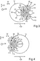
- Fig. 3 shows a third embodiment, wherein Fig. 4 shows a fourth embodiment.
- the axle drive device 10 can have a second electrical machine 110, wherein the previous and following explanations regarding the first electrical machine 34 can easily be transferred to the second electrical machine 110 and vice versa.
- a dashed line 113 is shown in each case, which covers an area C of Fig. 1 respectively from Fig. 2 surrounds.
- this area C components in the form of the electrical machine 34, the planetary gear stage 46 and the spur gear 60 are shown or contained, wherein the components shown or illustrated in the area C can advantageously be provided twice, which is shown in FIG Figures 3 and 4 is illustrated.
- a third planetary gear stage is assigned to the second electrical machine 110, to which the previous and following explanations relating to the electrical machine 34 and the spur gear 60 can easily be transferred, but then with regard to the second electrical machine 110 and to a further spur gear 112, which is driven by the second electrical machine 110, in particular via the in Fig. 3 with 114 designated third planetary gear stage, is drivable.
- the further spur gear 112 meshes with the second spur gear 62 of the first spur gear stage 48, so that, for example, the further spur gear 112 belongs to the first spur gear stage 48.
- the second electrical machine 110 also has a second stator and a second rotor, which can be rotated about a further machine axis of rotation 116 relative to the second stator.
- the respective rotor can be driven by the respective stator and can thereby be rotated about the respective machine axis of rotation 42 or 116.
- the machine axis of rotation 116 is arranged offset from the machine axis of rotation 42, from the main axis of rotation 84 and from the wheel axis of rotation 20.
- the main axis of rotation 84 and the wheel axis of rotation 20 lie in a plane spanned by the transverse direction of the vehicle and the longitudinal direction of the vehicle, which plane thus runs at least substantially perpendicular to the vertical direction of the vehicle.
- the machine axes of rotation 42 and 116 lie in a common plane spanned by the vertical direction of the vehicle and the transverse direction of the vehicle and, for example, perpendicular to the longitudinal direction of the vehicle, with the second electrical machine 110 in particular having the first electrical plane along a direction perpendicular to the transverse direction of the vehicle, in particular along the vertical direction of the vehicle Machine 34 is in alignment.
- the electrical machines 34 and 110 are arranged one above the other in the vertical direction of the vehicle, whereby they are arranged congruently, for example, in such a way that the electrical machine 110 is completely covered upward in the vertical direction of the vehicle by the electric machine 34, while the electrical machine 34 is downward in the vertical direction of the vehicle is completely covered by the electrical machine 110.
- the electrical machines 34 and 110 form a gusset 118 in which at least part of the spur gear 92 is arranged, so that the spur gear 92, in particular the mentioned part of the spur gear 92, in the vertical direction of the vehicle upwards through the electrical machine 34 and in the vertical direction of the vehicle is covered at the bottom by the electrical machine 110.
- FIG. 3 the forward direction of travel of the motor vehicle 12 is illustrated by an arrow 120.
- the electrical machines 34 and 110 are arranged in front of the drive wheel 14 and 18 or in front of the wheel axis of rotation 20, the electrical machine 34 and 110 in the case of FIG Fig. 4
- the fourth embodiment shown are arranged behind the drive wheel 14 or behind the wheel axis of rotation 20.
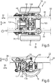
- Fig. 5 shows the motor vehicle 12 in sections in a schematic plan view, with FIG Fig. 5 the integration of the axle drive device 10 between the longitudinal members 24 and 26 can be seen particularly well.
- Fig. 5 122 designates an installation space which is available in particular in the third embodiment and in which, for example, power electronics and / or at least one cooler and, for example, oil and / or water connections can be arranged.
- the cooler is, for example, a heat exchanger and / or an oil and / or water cooler.
- Fig. 5 124 denotes an installation space that is available in the fourth embodiment in particular, in which, for example, power electronics and / or at least one cooler, in particular designed as a heat exchanger, and optionally oil and / or water connections can be arranged, the previous and following statements on the installation space 122 can also be transferred to the installation space 124 and vice versa. It is thus possible for a cooler, in particular an oil cooler, and / or power electronics to be arranged on a side of the first electrical machine 34 facing away from the axle gear 64 or on a side of the axle gear 64 facing away from the first electric machine 34.
- the first planetary gear stage 46 can be omitted, so that the second planetary gear stage 72 is then referred to as the first planetary gear stage, for example with regard to the designation or terminology, and is provided, for example, as the single planetary gear stage.
- the electrical machines 34 and 110 it is conceivable to provide only one of the electrical machines 34 and 110 in the axle drive device 10, so that, for example, precisely one electrical machine 34 or 110 is provided. A sufficiently advantageous drive of the drive wheels 14 and 18 with sufficient power can also be achieved in this way.
- an actuator 126 can be seen, by means of which, for example, the switching element 82 is movable, in particular displaceable, so that
- the actuator system 126 is the aforementioned actuator for moving or shifting the switching element 82.
- FIG. 6 the motor vehicle 12 excerpts in a schematic side view, wherein from Fig. 6 the placement of the electrical machines 34 and 110 arranged one above the other can be seen particularly well. Besides, it's off Fig. 6 a stabilization support 128 can be seen.
- the axle 16 designed for example as a front or rear axle
- the electric machines 34 and 110 which can be operated as electric motors
- the respective planetary gear stage 46 or 114 designed as a planetary gear
- directly on the respective electrical machine 34 or 110 is flanged on and thus forms, with the respective electrical machine 34 or 110, for example, a module that is particularly easy to handle and assemble.
- the second and first embodiment are connected to the spur gear stage 48 via the sun gear 74 in the manner described - in the second embodiment the second planetary gear stage 72 is connected via the ring gear 76 the first spur gear stage 48 is connected.
- the ring gear 76 has its internal toothing, via which the ring gear 76 meshes with the planet gears 80.
- the ring gear 76 for example, has external toothing by which the spur gear 62 is formed. The ring gear 76 or the spur gear 62 meshes with the spur gear 60 via the named external toothing of the ring gear 76.
- the sun gear 74 thus represents a drive for the planetary gear stage 72, with the second embodiment driving the planetary gear stage 72 through the ring gear 76 is realized.
- the Planet carrier 78 is an output of the planetary gear stage 72, which is connected to the second spur gear stage 90 via the output.
- the spur gear stage 90 is a further or second spur gear group via which the respective drive torque or the summed drive torques and thus a total torque resulting from the drive torques is transmitted to the axle gear 64, which is designed as a differential, for example.
Landscapes
- Engineering & Computer Science (AREA)
- Mechanical Engineering (AREA)
- Chemical & Material Sciences (AREA)
- Combustion & Propulsion (AREA)
- Transportation (AREA)
- General Engineering & Computer Science (AREA)
- Retarders (AREA)
- Electric Propulsion And Braking For Vehicles (AREA)
- Arrangement Or Mounting Of Propulsion Units For Vehicles (AREA)
Claims (13)
- Pont moteur électrique (10) pour un véhicule à moteur (12), comprenant au moins un premier moteur électrique (34), qui comporte un stator (36) et un rotor (38) qui peut tourner autour d'un axe de rotation de moteur (42) par rapport au stator (36), une transmission menée par le premier moteur électrique (34), qui- comporte exactement deux étages de satellites (46, 72), notamment un premier étage de satellites (46) mené par le premier moteur électrique (34) et un second étage de satellites (72) menée par le moteur électrique (34),- et exactement deux étages d'engrenages cylindriques (48, 90), notamment un premier étage d'engrenages cylindriques (48) mené par le premier moteur (34), qui comporte un première roue cylindrique (60) et une seconde roue cylindrique (62) s'engrenant avec la première roue cylindrique (60), et un second étages d'engrenages cylindriques (90),
et au moins une roue motrice (14) du véhicule à moteur (12) pouvant tourner autour d'un axe de rotation de roue parallèle à l'axe de rotation moteur (42) et pouvant être entraînée par la transmission (44) du premier moteur électrique (34),
une transmission finale (64) pouvant être entraînée par l'intermédiaire de la transmission (4) par le premier moteur (34), laquelle peut être entraînée la roue motrice (14) par le premier moteur électrique (34) ;- le premier moteur électrique (34), par rapport à un plan médian longitudinal s'étendant à la verticale du véhicule (32) et au sens de la longueur du véhicule (30), étant disposé au moins en partie sur un premier côté (68) du plan médian longitudinal (66) ;- le premier étage d'engrenages cylindriques (48) étant disposé sur un second côté (70) du plan médian longitudinal (66) en regard du premier côté (68) dans le sens transversal du véhicule (28)
caractérisé en ce que- par rapport à un flux de couple du premier moteur électrique (34) par rapport à la roue motrice (14), le premier étage de satellites (46) est disposé après le premier moteur électrique (34) et avant la roue motrice (14), le premier étage d'engrenages cylindriques (48) après le premier étage de satellites (46) et avant la roue motrice (14), le second étage de satellite (72) après le premier étage d'engrenages cylindriques (48) et avant la roue motrice (14) et le second étage d'engrenages cylindriques (90) après le second étage de satellites (72) et avant la roue motrice (14),- un élément de frein (82) permettant de fixer un élément de transmission du premier étage de satellites (46) ou un élément de transmission du second étage de satellites (72) sur un carter (58) de la transmission (44), l'élément de frein (82) présentant une couronne (76) pouvant se déplacer dans le sens axial de chaque étage de satellites (72) par rapport au carter (58). - Pont moteur électrique (10) selon la revendication 1, caractérisé en ce qu'au moins un élément de blocage (82) permet de bloquer au moins deux éléments de transmission du second étage de satellites (72).
- Pont moteur électrique (10) selon la revendication 1 ou la revendication 2, caractérisé en ce que le second étage de satellites (72) est disposé principalement sur le second côté (70).
- Pont moteur électrique (10) selon l'une quelconque des revendications précédentes, caractérisé en ce que le second étage d'engrenages cylindriques (90) est disposé essentiellement dans le plan médian longitudinal (66).
- Pont moteur électrique (10) selon l'une quelconque des revendications précédentes, caractérisé en ce que le moteur électrique (34) est disposé au moins pour deux tiers de son volume sur le premier côté (68).
- Pont moteur électrique (10) selon l'une quelconque des revendications précédentes, caractérisé en ce qu'il est prévu un second moteur électrique (110) et une autre roue cylindrique (112) engrenée par la seconde roue cylindrique (62) et pouvant être entrainée par le second moteur électrique (110).
- Pont moteur électrique (10) selon la revendication 6, caractérisé en ce que le second moteur électrique (110) est disposé, par rapport à un autre plan s'étendant dans le sens transversal du véhicule (28) et dans le sens longitudinal du véhicule (30) sur un troisième côté de l'autre plan, le premier moteur (34) étant disposé sur un quatrième côté de l'autre plan en regard du troisième côté dans le sens de la hauteur du véhicule.
- Pont moteur électrique (10) selon la revendication 6 ou la revendication 7, caractérisé en ce que le second moteur électrique (110) vient à fleur le long d'une direction s'étendant perpendiculaire au sens transversal du véhicule (28) avec le premier moteur électrique (34).
- Pont moteur électrique (10) selon l'une quelconque des revendications précédentes, caractérisé en ce que le premier étage de satellites (46), le premier moteur électrique (34) et le premier étage d'engrenages cylindriques (48) sont disposés dans un carter commun (58), le carter (58) étant disposé dans les mêmes proportions sur le premier côté (68) et sur le deuxième côté (70).
- Pont moteur électrique (10) selon l'une quelconque des revendications précédentes, caractérisé en ce qu'un refroidisseur d'huile et une électronique de puissance sont disposés sur un côté du premier moteur électrique (34) opposé à la transmission finale (64).
- Pont moteur électrique (10) selon l'une quelconque des revendications précédentes caractérisé en ce qu'une seconde roue motrice (18) et un essieu rigide qui permet d'accoupler ensemble la roue motrice (14) et la seconde roue motrice (18), un carter secondaire servant à loger la transmission (44) le carter secondaire présentant une bride qui peut être reliée ou est reliée à une seconde bride de la transmission finale (64).
- Véhicule utilitaire (12) comprenant un pont moteur électrique (10) selon l'une quelconque des revendications précédentes, caractérisé par deux longerons (24, 26), les deux étages de satellites (46, 72), les deux étages d'engrenages cylindriques (48, 90), le premier et le second moteur électrique (34, 110) sont tous disposés dans le sens transversal du véhicule (28) entre les longerons (24, 26),
le premier et le second moteur électrique (34, 110) étant les seules moteurs d'entraînement du pont moteur (10). - Pont moteur électrique (10) pour un véhicule à moteur (12), comprenant au moins un premier moteur électrique (34) qui comporte un stator (36) et un rotor (38) qui peut tourner autour d'un axe de rotation de moteur (42) par rapport au stator (36), une transmission menée par le premier moteur électrique (34), qui- comporte exactement deux étages de satellites (46, 72), notamment un premier étage de satellites (46) mené par le premier moteur électrique (34) et un second étage de satellites (72) menée par le moteur électrique (34),- et exactement deux étages d'engrenages cylindriques (48, 90), notamment un premier étage d'engrenages cylindriques (48) mené par le premier moteur (34), qui comporte un première roue cylindrique (60) et une seconde roue cylindrique (62) s'engrenant avec la première roue cylindrique (60), et un second étages d'engrenages cylindriques (90),
et au moins une roue motrice (14) du véhicule à moteur (12) pouvant tourner autour d'un axe de rotation de roue parallèle à l'axe de rotation moteur (42) et pouvant être entraînée par la transmission (44) du premier moteur électrique (34),
une transmission finale (64) pouvant être entraînée par l'intermédiaire de la transmission (44) par le premier moteur (34), laquelle peut être entraînée la roue motrice (14) par le premier moteur électrique (34) ;- le premier moteur électrique (34), par rapport à un plan médian longitudinal (66) du véhicule à moteur (12) s'étendant à la verticale du véhicule (32) et au sens de la longueur du véhicule (30), étant disposé au moins en partie sur un premier côté (68) du plan médian longitudinal (66) ;- le premier étage d'engrenages cylindriques (48) étant disposé sur un second côté (70) du plan médian longitudinal (66) en regard du premier côté (68) dans le sens transversal du véhicule (28)
caractérisé en ce que- par rapport à un flux de couple du premier moteur électrique (34) par rapport à la roue motrice (14), le premier étage de satellites (46) est disposé après le premier moteur électrique (34) et avant la roue motrice (14), le premier étage d'engrenages cylindriques (48) après le premier étage de satellites (46) et avant la roue motrice (14), le second étage de satellite (72) après le premier étage d'engrenages cylindriques (48) et avant la roue motrice (14) et le second étage d'engrenages cylindriques (90) après le second étage de satellites (72) et avant la roue motrice (14),- un élément de frein (82) permettant de fixer un élément de transmission du premier étage de satellites (46) ou un élément de transmission du second étage de satellites (72) sur un carter (58) de la transmission (44), l'élément de frein (82) présentant une couronne (74) du second étage de satellites (72) pouvant se déplacer dans le sens axial de chaque étage de satellites (72) par rapport au carter (58).
Applications Claiming Priority (2)
| Application Number | Priority Date | Filing Date | Title |
|---|---|---|---|
| DE102017007081.4A DE102017007081B4 (de) | 2017-07-27 | 2017-07-27 | Elektrische Achsantriebsvorrichtung für ein Kraftfahrzeug, insbesondere für ein Nutzfahrzeug, sowie Kraftfahrzeug mit wenigstens einer solchen elektrischen Achsantriebsvorrichtung |
| PCT/EP2018/066878 WO2019020297A1 (fr) | 2017-07-27 | 2018-06-25 | Dispositif d'entraînement d'essieu électrique pour un véhicule automobile, et véhicule utilitaire associé |
Publications (2)
| Publication Number | Publication Date |
|---|---|
| EP3658397A1 EP3658397A1 (fr) | 2020-06-03 |
| EP3658397B1 true EP3658397B1 (fr) | 2021-05-12 |
Family
ID=62846142
Family Applications (1)
| Application Number | Title | Priority Date | Filing Date |
|---|---|---|---|
| EP18738212.2A Active EP3658397B1 (fr) | 2017-07-27 | 2018-06-25 | Ensemble d'entraînement électrique d'un essieu pour un véhicule automobile, et véhicule utilitaire associé |
Country Status (5)
| Country | Link |
|---|---|
| US (1) | US11331992B2 (fr) |
| EP (1) | EP3658397B1 (fr) |
| CN (1) | CN110891812B (fr) |
| DE (1) | DE102017007081B4 (fr) |
| WO (1) | WO2019020297A1 (fr) |
Families Citing this family (4)
| Publication number | Priority date | Publication date | Assignee | Title |
|---|---|---|---|---|
| DE102018121221A1 (de) * | 2018-08-30 | 2020-03-05 | Man Truck & Bus Se | Lastkraftwagen mit einer elektrischen Antriebseinheit |
| CN112493949A (zh) * | 2020-12-18 | 2021-03-16 | 马美凤 | 一种防头发缠绕的扫地机器人车轮 |
| CN117841655A (zh) * | 2022-09-30 | 2024-04-09 | 浙江春风动力股份有限公司 | 全地形车 |
| NL2038203B1 (en) | 2024-07-11 | 2026-01-29 | Daf Trucks Nv | Electric axle drive for a vehicle wheel axle |
Family Cites Families (23)
| Publication number | Priority date | Publication date | Assignee | Title |
|---|---|---|---|---|
| US6387004B1 (en) * | 1999-04-30 | 2002-05-14 | Trw Inc. | Continuously variable transmission |
| EP1477985A1 (fr) | 2003-05-14 | 2004-11-17 | Deutsche Thomson-Brandt Gmbh | Procédé et appareil pour détecter des creux d'en-tête sur une partie plate intermédiaire |
| US6978853B2 (en) * | 2003-07-30 | 2005-12-27 | Arvinmeritor Technology Llc | Axle assembly with parallel mounted electric motors |
| US7210802B2 (en) | 2003-11-06 | 2007-05-01 | Gloria Buley | Mirror for improved visibility of danger zone area on right side of school buses |
| US20090098969A1 (en) * | 2005-06-24 | 2009-04-16 | Toyota Jidosha Kabushiki Kaisha | Drive device for vehicle |
| US7309300B2 (en) | 2005-11-23 | 2007-12-18 | Caterpillar Inc. | Electric drive system with plural motors |
| DE112008003105T5 (de) * | 2007-11-20 | 2010-09-30 | Magna Powertrain USA, Inc., Troy | Zweigang-Transaxle-Getriebe für Elektrofahrzeuge |
| CN101451596B (zh) * | 2007-12-04 | 2012-01-11 | 艾晓林 | 双模式机电无级变速器 |
| DE102009033531A1 (de) | 2009-07-10 | 2011-01-20 | Dr. Ing. H.C. F. Porsche Aktiengesellschaft | Antriebsvorrichtung für ein Kraftfahrzeug mit einer elektrische Maschinen aufweisenden Portalachse |
| US20110094807A1 (en) * | 2009-10-26 | 2011-04-28 | Steve Pruitt | Electric drive system for passive vehicle |
| DE102010017966A1 (de) | 2010-04-23 | 2011-10-27 | Dr. Ing. H.C. F. Porsche Aktiengesellschaft | Fahrzeug mit elektrischem Antrieb |
| JP6028507B2 (ja) * | 2011-10-28 | 2016-11-16 | 日本精工株式会社 | 電気自動車用駆動装置 |
| DE102012206142A1 (de) * | 2012-04-16 | 2013-10-17 | Siemens Aktiengesellschaft | Antriebsvorrichtung für einen Kraftwagen |
| DE102012024752A1 (de) * | 2012-12-17 | 2014-06-18 | Volkswagen Aktiengesellschaft | Übersetzungs- und Ausgleichsgetriebe sowie Motor- und Getriebeeinheit |
| DE102013016441B4 (de) * | 2013-09-27 | 2018-02-01 | Iav Gmbh Ingenieurgesellschaft Auto Und Verkehr | Vorrichtung zum Antrieb eines Fahrzeuges |
| CN203766511U (zh) * | 2014-02-13 | 2014-08-13 | 河北德辰工程技术有限公司 | 一体式电驱动车桥 |
| DE102015101042B4 (de) * | 2015-01-26 | 2022-11-03 | Dr. Ing. H.C. F. Porsche Aktiengesellschaft | Elektrisch antreibbare Achse für ein Kraftfahrzeug |
| DE102015208825A1 (de) * | 2015-05-12 | 2016-11-17 | Schaeffler Technologies AG & Co. KG | Antriebsanordnung für ein Fahrzeug mit schaltbarem Getriebestufenabschnitt sowie Fahrzeug mit der Antriebsanordnung |
| US9453564B1 (en) * | 2015-11-09 | 2016-09-27 | Borgwarner Inc. | Electric all-wheel drive with two-speed double reduction planetary |
| KR20180086453A (ko) | 2015-11-24 | 2018-07-31 | 보그워너 스웨덴 아베 | 차량 구동라인 시스템 |
| DE102015016939A1 (de) | 2015-12-24 | 2017-06-29 | Daimler Ag | Antriebsstrangvorrichtung mit einem Elektromotor |
| CN107191553B (zh) * | 2016-03-14 | 2021-08-17 | 博格华纳公司 | 产品和驱动车桥差速器的方法 |
| CN205631969U (zh) * | 2016-05-27 | 2016-10-12 | 长城汽车股份有限公司 | 车辆的驱动车桥及车辆 |
-
2017
- 2017-07-27 DE DE102017007081.4A patent/DE102017007081B4/de not_active Expired - Fee Related
-
2018
- 2018-06-25 WO PCT/EP2018/066878 patent/WO2019020297A1/fr not_active Ceased
- 2018-06-25 US US16/634,417 patent/US11331992B2/en active Active
- 2018-06-25 EP EP18738212.2A patent/EP3658397B1/fr active Active
- 2018-06-25 CN CN201880047208.5A patent/CN110891812B/zh active Active
Non-Patent Citations (1)
| Title |
|---|
| None * |
Also Published As
| Publication number | Publication date |
|---|---|
| WO2019020297A1 (fr) | 2019-01-31 |
| CN110891812A (zh) | 2020-03-17 |
| DE102017007081A1 (de) | 2019-01-31 |
| CN110891812B (zh) | 2023-03-14 |
| DE102017007081B4 (de) | 2019-06-06 |
| US11331992B2 (en) | 2022-05-17 |
| EP3658397A1 (fr) | 2020-06-03 |
| US20200171929A1 (en) | 2020-06-04 |
Similar Documents
| Publication | Publication Date | Title |
|---|---|---|
| EP2176085B1 (fr) | Train d'entraînement pour véhicule automobile | |
| DE102006046419B4 (de) | Elektrische Achsantriebsbaugruppe | |
| EP4135992A1 (fr) | Bloc d'entraînement compact d'un entraînement de véhicule à moteur électrique, notamment doté d'un bloc inverseur ou d'un dispositif de frein de stationnement | |
| DE102018005947A1 (de) | Elektrischer Antriebsstrang für ein Kraftfahrzeug, insbesondere für einen Kraftwagen | |
| EP3658397B1 (fr) | Ensemble d'entraînement électrique d'un essieu pour un véhicule automobile, et véhicule utilitaire associé | |
| DE102013202382A1 (de) | Antriebsvorrichtung für ein Fahrzeug sowie Fahrzeug mit der Antriebsvorrichtung | |
| DE102005030420A1 (de) | Hybridgetriebe | |
| EP3870879A1 (fr) | Boîte de vitesses à plusieurs rapports commandée en charge | |
| DE202010001318U1 (de) | Elektrische Achsantriebsbaugruppe | |
| DE102022000463B3 (de) | Elektrische Antriebseinheit für ein Kraftfahrzeug mit wählbarer Boost- oder Torque-Vectoring- Funktion | |
| DE102023133013A1 (de) | Mehrgängige Dual-Motor-Antriebseinheit sowie Drehmomentenverteilung im Achsantrieb für ein Kraftfahrzeug | |
| EP4437249A1 (fr) | Entraînement d'essieu électrique pour un essieu d'un véhicule à moteur, en particulier une voiture à moteur, et véhicule à moteur, en particulier voiture à moteur | |
| DE102018000195B4 (de) | Getriebeeinrichtung für ein Kraftfahrzeug, insbesondere für einen Kraftwagen | |
| DE102022204751A1 (de) | Achssystem, Antriebssystem und Fahrzeug | |
| DE102018207749A1 (de) | Schaltbares Radnabengetriebe | |
| DE102021004615B4 (de) | Antriebseinrichtung für ein Kraftfahrzeug, insbesondere für einen Kraftwagen | |
| DE102015008835A1 (de) | Antriebseinrichtung für einen Kraftwagen, insbesondere einen Personenkraftwagen | |
| DE102021004159B3 (de) | Elektrische Antriebsvorrichtung für ein Kraftfahrzeug, insbesondere für einen Kraftwagen | |
| DE102023130930A1 (de) | Elektrisches Antriebssystem | |
| DE102022214115A1 (de) | Kraftfahrzeuggetriebe für ein zumindest teilweise elektrisch angetriebenes Kraftfahrzeug | |
| WO2013156259A1 (fr) | Unité à moto-réducteur | |
| EP4334150B1 (fr) | Véhicule à moteur, en particulier véhicule utilitaire | |
| DE102019001516A1 (de) | Antriebsstrang für ein Kraftfahrzeug, insbesondere für einen Kraftwagen | |
| DE102019005151A1 (de) | Antriebseinrichtung für einen Kraftwagen, insbesondere für einen Personenkraftwagen | |
| DE102020111421B4 (de) | Verfahren zur Steuerung eines Klimakompressors in einem Hybridantriebsstrang und Hybridantriebsstrang |
Legal Events
| Date | Code | Title | Description |
|---|---|---|---|
| STAA | Information on the status of an ep patent application or granted ep patent |
Free format text: STATUS: UNKNOWN |
|
| STAA | Information on the status of an ep patent application or granted ep patent |
Free format text: STATUS: THE INTERNATIONAL PUBLICATION HAS BEEN MADE |
|
| PUAI | Public reference made under article 153(3) epc to a published international application that has entered the european phase |
Free format text: ORIGINAL CODE: 0009012 |
|
| STAA | Information on the status of an ep patent application or granted ep patent |
Free format text: STATUS: REQUEST FOR EXAMINATION WAS MADE |
|
| 17P | Request for examination filed |
Effective date: 20200116 |
|
| AK | Designated contracting states |
Kind code of ref document: A1 Designated state(s): AL AT BE BG CH CY CZ DE DK EE ES FI FR GB GR HR HU IE IS IT LI LT LU LV MC MK MT NL NO PL PT RO RS SE SI SK SM TR |
|
| AX | Request for extension of the european patent |
Extension state: BA ME |
|
| DAV | Request for validation of the european patent (deleted) | ||
| DAX | Request for extension of the european patent (deleted) | ||
| GRAP | Despatch of communication of intention to grant a patent |
Free format text: ORIGINAL CODE: EPIDOSNIGR1 |
|
| STAA | Information on the status of an ep patent application or granted ep patent |
Free format text: STATUS: GRANT OF PATENT IS INTENDED |
|
| INTG | Intention to grant announced |
Effective date: 20201113 |
|
| GRAS | Grant fee paid |
Free format text: ORIGINAL CODE: EPIDOSNIGR3 |
|
| GRAA | (expected) grant |
Free format text: ORIGINAL CODE: 0009210 |
|
| STAA | Information on the status of an ep patent application or granted ep patent |
Free format text: STATUS: THE PATENT HAS BEEN GRANTED |
|
| AK | Designated contracting states |
Kind code of ref document: B1 Designated state(s): AL AT BE BG CH CY CZ DE DK EE ES FI FR GB GR HR HU IE IS IT LI LT LU LV MC MK MT NL NO PL PT RO RS SE SI SK SM TR |
|
| REG | Reference to a national code |
Ref country code: GB Ref legal event code: FG4D Free format text: NOT ENGLISH |
|
| REG | Reference to a national code |
Ref country code: CH Ref legal event code: EP |
|
| REG | Reference to a national code |
Ref country code: DE Ref legal event code: R096 Ref document number: 502018005261 Country of ref document: DE |
|
| REG | Reference to a national code |
Ref country code: IE Ref legal event code: FG4D Free format text: LANGUAGE OF EP DOCUMENT: GERMAN |
|
| REG | Reference to a national code |
Ref country code: AT Ref legal event code: REF Ref document number: 1391961 Country of ref document: AT Kind code of ref document: T Effective date: 20210615 |
|
| REG | Reference to a national code |
Ref country code: LT Ref legal event code: MG9D |
|
| REG | Reference to a national code |
Ref country code: NL Ref legal event code: MP Effective date: 20210512 |
|
| PG25 | Lapsed in a contracting state [announced via postgrant information from national office to epo] |
Ref country code: FI Free format text: LAPSE BECAUSE OF FAILURE TO SUBMIT A TRANSLATION OF THE DESCRIPTION OR TO PAY THE FEE WITHIN THE PRESCRIBED TIME-LIMIT Effective date: 20210512 Ref country code: HR Free format text: LAPSE BECAUSE OF FAILURE TO SUBMIT A TRANSLATION OF THE DESCRIPTION OR TO PAY THE FEE WITHIN THE PRESCRIBED TIME-LIMIT Effective date: 20210512 Ref country code: LT Free format text: LAPSE BECAUSE OF FAILURE TO SUBMIT A TRANSLATION OF THE DESCRIPTION OR TO PAY THE FEE WITHIN THE PRESCRIBED TIME-LIMIT Effective date: 20210512 Ref country code: BG Free format text: LAPSE BECAUSE OF FAILURE TO SUBMIT A TRANSLATION OF THE DESCRIPTION OR TO PAY THE FEE WITHIN THE PRESCRIBED TIME-LIMIT Effective date: 20210812 |
|
| PG25 | Lapsed in a contracting state [announced via postgrant information from national office to epo] |
Ref country code: PL Free format text: LAPSE BECAUSE OF FAILURE TO SUBMIT A TRANSLATION OF THE DESCRIPTION OR TO PAY THE FEE WITHIN THE PRESCRIBED TIME-LIMIT Effective date: 20210512 Ref country code: NO Free format text: LAPSE BECAUSE OF FAILURE TO SUBMIT A TRANSLATION OF THE DESCRIPTION OR TO PAY THE FEE WITHIN THE PRESCRIBED TIME-LIMIT Effective date: 20210812 Ref country code: LV Free format text: LAPSE BECAUSE OF FAILURE TO SUBMIT A TRANSLATION OF THE DESCRIPTION OR TO PAY THE FEE WITHIN THE PRESCRIBED TIME-LIMIT Effective date: 20210512 Ref country code: PT Free format text: LAPSE BECAUSE OF FAILURE TO SUBMIT A TRANSLATION OF THE DESCRIPTION OR TO PAY THE FEE WITHIN THE PRESCRIBED TIME-LIMIT Effective date: 20210913 Ref country code: SE Free format text: LAPSE BECAUSE OF FAILURE TO SUBMIT A TRANSLATION OF THE DESCRIPTION OR TO PAY THE FEE WITHIN THE PRESCRIBED TIME-LIMIT Effective date: 20210512 Ref country code: RS Free format text: LAPSE BECAUSE OF FAILURE TO SUBMIT A TRANSLATION OF THE DESCRIPTION OR TO PAY THE FEE WITHIN THE PRESCRIBED TIME-LIMIT Effective date: 20210512 Ref country code: IS Free format text: LAPSE BECAUSE OF FAILURE TO SUBMIT A TRANSLATION OF THE DESCRIPTION OR TO PAY THE FEE WITHIN THE PRESCRIBED TIME-LIMIT Effective date: 20210912 Ref country code: GR Free format text: LAPSE BECAUSE OF FAILURE TO SUBMIT A TRANSLATION OF THE DESCRIPTION OR TO PAY THE FEE WITHIN THE PRESCRIBED TIME-LIMIT Effective date: 20210813 |
|
| PG25 | Lapsed in a contracting state [announced via postgrant information from national office to epo] |
Ref country code: NL Free format text: LAPSE BECAUSE OF FAILURE TO SUBMIT A TRANSLATION OF THE DESCRIPTION OR TO PAY THE FEE WITHIN THE PRESCRIBED TIME-LIMIT Effective date: 20210512 |
|
| PG25 | Lapsed in a contracting state [announced via postgrant information from national office to epo] |
Ref country code: SK Free format text: LAPSE BECAUSE OF FAILURE TO SUBMIT A TRANSLATION OF THE DESCRIPTION OR TO PAY THE FEE WITHIN THE PRESCRIBED TIME-LIMIT Effective date: 20210512 Ref country code: EE Free format text: LAPSE BECAUSE OF FAILURE TO SUBMIT A TRANSLATION OF THE DESCRIPTION OR TO PAY THE FEE WITHIN THE PRESCRIBED TIME-LIMIT Effective date: 20210512 Ref country code: ES Free format text: LAPSE BECAUSE OF FAILURE TO SUBMIT A TRANSLATION OF THE DESCRIPTION OR TO PAY THE FEE WITHIN THE PRESCRIBED TIME-LIMIT Effective date: 20210512 Ref country code: SM Free format text: LAPSE BECAUSE OF FAILURE TO SUBMIT A TRANSLATION OF THE DESCRIPTION OR TO PAY THE FEE WITHIN THE PRESCRIBED TIME-LIMIT Effective date: 20210512 Ref country code: RO Free format text: LAPSE BECAUSE OF FAILURE TO SUBMIT A TRANSLATION OF THE DESCRIPTION OR TO PAY THE FEE WITHIN THE PRESCRIBED TIME-LIMIT Effective date: 20210512 Ref country code: CZ Free format text: LAPSE BECAUSE OF FAILURE TO SUBMIT A TRANSLATION OF THE DESCRIPTION OR TO PAY THE FEE WITHIN THE PRESCRIBED TIME-LIMIT Effective date: 20210512 Ref country code: DK Free format text: LAPSE BECAUSE OF FAILURE TO SUBMIT A TRANSLATION OF THE DESCRIPTION OR TO PAY THE FEE WITHIN THE PRESCRIBED TIME-LIMIT Effective date: 20210512 |
|
| REG | Reference to a national code |
Ref country code: CH Ref legal event code: PL |
|
| REG | Reference to a national code |
Ref country code: DE Ref legal event code: R097 Ref document number: 502018005261 Country of ref document: DE |
|
| REG | Reference to a national code |
Ref country code: BE Ref legal event code: MM Effective date: 20210630 |
|
| REG | Reference to a national code |
Ref country code: DE Ref legal event code: R081 Ref document number: 502018005261 Country of ref document: DE Owner name: DAIMLER TRUCK AG, DE Free format text: FORMER OWNER: DAIMLER AG, 70372 STUTTGART, DE |
|
| PLBE | No opposition filed within time limit |
Free format text: ORIGINAL CODE: 0009261 |
|
| STAA | Information on the status of an ep patent application or granted ep patent |
Free format text: STATUS: NO OPPOSITION FILED WITHIN TIME LIMIT |
|
| PG25 | Lapsed in a contracting state [announced via postgrant information from national office to epo] |
Ref country code: MC Free format text: LAPSE BECAUSE OF FAILURE TO SUBMIT A TRANSLATION OF THE DESCRIPTION OR TO PAY THE FEE WITHIN THE PRESCRIBED TIME-LIMIT Effective date: 20210512 Ref country code: LU Free format text: LAPSE BECAUSE OF NON-PAYMENT OF DUE FEES Effective date: 20210625 |
|
| 26N | No opposition filed |
Effective date: 20220215 |
|
| PG25 | Lapsed in a contracting state [announced via postgrant information from national office to epo] |
Ref country code: LI Free format text: LAPSE BECAUSE OF NON-PAYMENT OF DUE FEES Effective date: 20210630 Ref country code: IE Free format text: LAPSE BECAUSE OF NON-PAYMENT OF DUE FEES Effective date: 20210625 Ref country code: CH Free format text: LAPSE BECAUSE OF NON-PAYMENT OF DUE FEES Effective date: 20210630 |
|
| PG25 | Lapsed in a contracting state [announced via postgrant information from national office to epo] |
Ref country code: IS Free format text: LAPSE BECAUSE OF FAILURE TO SUBMIT A TRANSLATION OF THE DESCRIPTION OR TO PAY THE FEE WITHIN THE PRESCRIBED TIME-LIMIT Effective date: 20210912 Ref country code: FR Free format text: LAPSE BECAUSE OF NON-PAYMENT OF DUE FEES Effective date: 20210712 Ref country code: AL Free format text: LAPSE BECAUSE OF FAILURE TO SUBMIT A TRANSLATION OF THE DESCRIPTION OR TO PAY THE FEE WITHIN THE PRESCRIBED TIME-LIMIT Effective date: 20210512 |
|
| PG25 | Lapsed in a contracting state [announced via postgrant information from national office to epo] |
Ref country code: IT Free format text: LAPSE BECAUSE OF FAILURE TO SUBMIT A TRANSLATION OF THE DESCRIPTION OR TO PAY THE FEE WITHIN THE PRESCRIBED TIME-LIMIT Effective date: 20210512 Ref country code: BE Free format text: LAPSE BECAUSE OF NON-PAYMENT OF DUE FEES Effective date: 20210630 |
|
| GBPC | Gb: european patent ceased through non-payment of renewal fee |
Effective date: 20220625 |
|
| PG25 | Lapsed in a contracting state [announced via postgrant information from national office to epo] |
Ref country code: GB Free format text: LAPSE BECAUSE OF NON-PAYMENT OF DUE FEES Effective date: 20220625 |
|
| PG25 | Lapsed in a contracting state [announced via postgrant information from national office to epo] |
Ref country code: CY Free format text: LAPSE BECAUSE OF FAILURE TO SUBMIT A TRANSLATION OF THE DESCRIPTION OR TO PAY THE FEE WITHIN THE PRESCRIBED TIME-LIMIT Effective date: 20210512 |
|
| P01 | Opt-out of the competence of the unified patent court (upc) registered |
Effective date: 20230609 |
|
| PG25 | Lapsed in a contracting state [announced via postgrant information from national office to epo] |
Ref country code: HU Free format text: LAPSE BECAUSE OF FAILURE TO SUBMIT A TRANSLATION OF THE DESCRIPTION OR TO PAY THE FEE WITHIN THE PRESCRIBED TIME-LIMIT; INVALID AB INITIO Effective date: 20180625 |
|
| PG25 | Lapsed in a contracting state [announced via postgrant information from national office to epo] |
Ref country code: MK Free format text: LAPSE BECAUSE OF FAILURE TO SUBMIT A TRANSLATION OF THE DESCRIPTION OR TO PAY THE FEE WITHIN THE PRESCRIBED TIME-LIMIT Effective date: 20210512 |
|
| REG | Reference to a national code |
Ref country code: AT Ref legal event code: MM01 Ref document number: 1391961 Country of ref document: AT Kind code of ref document: T Effective date: 20230625 |
|
| PG25 | Lapsed in a contracting state [announced via postgrant information from national office to epo] |
Ref country code: MT Free format text: LAPSE BECAUSE OF FAILURE TO SUBMIT A TRANSLATION OF THE DESCRIPTION OR TO PAY THE FEE WITHIN THE PRESCRIBED TIME-LIMIT Effective date: 20210512 |
|
| PG25 | Lapsed in a contracting state [announced via postgrant information from national office to epo] |
Ref country code: AT Free format text: LAPSE BECAUSE OF NON-PAYMENT OF DUE FEES Effective date: 20230625 |
|
| PG25 | Lapsed in a contracting state [announced via postgrant information from national office to epo] |
Ref country code: AT Free format text: LAPSE BECAUSE OF NON-PAYMENT OF DUE FEES Effective date: 20230625 |
|
| PGFP | Annual fee paid to national office [announced via postgrant information from national office to epo] |
Ref country code: DE Payment date: 20250626 Year of fee payment: 8 |
|
| PG25 | Lapsed in a contracting state [announced via postgrant information from national office to epo] |
Ref country code: TR Free format text: LAPSE BECAUSE OF FAILURE TO SUBMIT A TRANSLATION OF THE DESCRIPTION OR TO PAY THE FEE WITHIN THE PRESCRIBED TIME-LIMIT Effective date: 20210512 |
|
| PGFP | Annual fee paid to national office [announced via postgrant information from national office to epo] |
Ref country code: AT Payment date: 20260410 Year of fee payment: 5 |