EP3658426B1 - Anordnung eines scheibenwischerblattverbinders - Google Patents
Anordnung eines scheibenwischerblattverbinders Download PDFInfo
- Publication number
- EP3658426B1 EP3658426B1 EP18838787.2A EP18838787A EP3658426B1 EP 3658426 B1 EP3658426 B1 EP 3658426B1 EP 18838787 A EP18838787 A EP 18838787A EP 3658426 B1 EP3658426 B1 EP 3658426B1
- Authority
- EP
- European Patent Office
- Prior art keywords
- wiper blade
- connector
- blade connector
- cover
- side walls
- Prior art date
- Legal status (The legal status is an assumption and is not a legal conclusion. Google has not performed a legal analysis and makes no representation as to the accuracy of the status listed.)
- Active
Links
Images


















Classifications
-
- B—PERFORMING OPERATIONS; TRANSPORTING
- B60—VEHICLES IN GENERAL
- B60S—SERVICING, CLEANING, REPAIRING, SUPPORTING, LIFTING, OR MANOEUVRING OF VEHICLES, NOT OTHERWISE PROVIDED FOR
- B60S1/00—Cleaning of vehicles
- B60S1/02—Cleaning windscreens, windows or optical devices
- B60S1/04—Wipers or the like, e.g. scrapers
- B60S1/32—Wipers or the like, e.g. scrapers characterised by constructional features of wiper blade arms or blades
- B60S1/38—Wiper blades
- B60S1/3801—Wiper blades characterised by a blade support harness consisting of several articulated elements
-
- B—PERFORMING OPERATIONS; TRANSPORTING
- B60—VEHICLES IN GENERAL
- B60S—SERVICING, CLEANING, REPAIRING, SUPPORTING, LIFTING, OR MANOEUVRING OF VEHICLES, NOT OTHERWISE PROVIDED FOR
- B60S1/00—Cleaning of vehicles
- B60S1/02—Cleaning windscreens, windows or optical devices
- B60S1/04—Wipers or the like, e.g. scrapers
- B60S1/32—Wipers or the like, e.g. scrapers characterised by constructional features of wiper blade arms or blades
- B60S1/40—Connections between blades and arms
- B60S1/4006—Connections between blades and arms for arms provided with a hook-shaped end
- B60S1/4009—Connections between blades and arms for arms provided with a hook-shaped end comprising a detachable intermediate element mounted on the hook-shaped end
-
- B—PERFORMING OPERATIONS; TRANSPORTING
- B60—VEHICLES IN GENERAL
- B60S—SERVICING, CLEANING, REPAIRING, SUPPORTING, LIFTING, OR MANOEUVRING OF VEHICLES, NOT OTHERWISE PROVIDED FOR
- B60S1/00—Cleaning of vehicles
- B60S1/02—Cleaning windscreens, windows or optical devices
- B60S1/04—Wipers or the like, e.g. scrapers
- B60S1/32—Wipers or the like, e.g. scrapers characterised by constructional features of wiper blade arms or blades
- B60S1/40—Connections between blades and arms
- B60S1/4003—Multi-purpose connections for two or more kinds of arm ends
-
- F—MECHANICAL ENGINEERING; LIGHTING; HEATING; WEAPONS; BLASTING
- F16—ENGINEERING ELEMENTS AND UNITS; GENERAL MEASURES FOR PRODUCING AND MAINTAINING EFFECTIVE FUNCTIONING OF MACHINES OR INSTALLATIONS; THERMAL INSULATION IN GENERAL
- F16B—DEVICES FOR FASTENING OR SECURING CONSTRUCTIONAL ELEMENTS OR MACHINE PARTS TOGETHER, e.g. NAILS, BOLTS, CIRCLIPS, CLAMPS, CLIPS OR WEDGES; JOINTS OR JOINTING
- F16B45/00—Hooks; Eyes
-
- F—MECHANICAL ENGINEERING; LIGHTING; HEATING; WEAPONS; BLASTING
- F16—ENGINEERING ELEMENTS AND UNITS; GENERAL MEASURES FOR PRODUCING AND MAINTAINING EFFECTIVE FUNCTIONING OF MACHINES OR INSTALLATIONS; THERMAL INSULATION IN GENERAL
- F16B—DEVICES FOR FASTENING OR SECURING CONSTRUCTIONAL ELEMENTS OR MACHINE PARTS TOGETHER, e.g. NAILS, BOLTS, CIRCLIPS, CLAMPS, CLIPS OR WEDGES; JOINTS OR JOINTING
- F16B5/00—Joining sheets or plates, e.g. panels, to one another or to strips or bars parallel to them
- F16B5/12—Fastening strips or bars to sheets or plates, e.g. rubber strips, decorative strips for motor vehicles, by means of clips
-
- F—MECHANICAL ENGINEERING; LIGHTING; HEATING; WEAPONS; BLASTING
- F16—ENGINEERING ELEMENTS AND UNITS; GENERAL MEASURES FOR PRODUCING AND MAINTAINING EFFECTIVE FUNCTIONING OF MACHINES OR INSTALLATIONS; THERMAL INSULATION IN GENERAL
- F16B—DEVICES FOR FASTENING OR SECURING CONSTRUCTIONAL ELEMENTS OR MACHINE PARTS TOGETHER, e.g. NAILS, BOLTS, CIRCLIPS, CLAMPS, CLIPS OR WEDGES; JOINTS OR JOINTING
- F16B5/00—Joining sheets or plates, e.g. panels, to one another or to strips or bars parallel to them
- F16B5/12—Fastening strips or bars to sheets or plates, e.g. rubber strips, decorative strips for motor vehicles, by means of clips
- F16B5/123—Auxiliary fasteners specially designed for this purpose
-
- B—PERFORMING OPERATIONS; TRANSPORTING
- B60—VEHICLES IN GENERAL
- B60S—SERVICING, CLEANING, REPAIRING, SUPPORTING, LIFTING, OR MANOEUVRING OF VEHICLES, NOT OTHERWISE PROVIDED FOR
- B60S1/00—Cleaning of vehicles
- B60S1/02—Cleaning windscreens, windows or optical devices
- B60S1/04—Wipers or the like, e.g. scrapers
- B60S1/0491—Additional elements being fixed on wipers or parts of wipers not otherwise provided for, e.g. covers, antennae or lights
-
- B—PERFORMING OPERATIONS; TRANSPORTING
- B60—VEHICLES IN GENERAL
- B60S—SERVICING, CLEANING, REPAIRING, SUPPORTING, LIFTING, OR MANOEUVRING OF VEHICLES, NOT OTHERWISE PROVIDED FOR
- B60S1/00—Cleaning of vehicles
- B60S1/02—Cleaning windscreens, windows or optical devices
- B60S1/04—Wipers or the like, e.g. scrapers
- B60S1/32—Wipers or the like, e.g. scrapers characterised by constructional features of wiper blade arms or blades
- B60S1/40—Connections between blades and arms
- B60S1/4006—Connections between blades and arms for arms provided with a hook-shaped end
- B60S1/4009—Connections between blades and arms for arms provided with a hook-shaped end comprising a detachable intermediate element mounted on the hook-shaped end
- B60S1/4016—Connections between blades and arms for arms provided with a hook-shaped end comprising a detachable intermediate element mounted on the hook-shaped end the element being provided with retention means co-operating with the hook-shaped end of the arm
- B60S1/4019—Connections between blades and arms for arms provided with a hook-shaped end comprising a detachable intermediate element mounted on the hook-shaped end the element being provided with retention means co-operating with the hook-shaped end of the arm the retention means being protrusions or holes
-
- B—PERFORMING OPERATIONS; TRANSPORTING
- B60—VEHICLES IN GENERAL
- B60S—SERVICING, CLEANING, REPAIRING, SUPPORTING, LIFTING, OR MANOEUVRING OF VEHICLES, NOT OTHERWISE PROVIDED FOR
- B60S1/00—Cleaning of vehicles
- B60S1/02—Cleaning windscreens, windows or optical devices
- B60S1/04—Wipers or the like, e.g. scrapers
- B60S1/32—Wipers or the like, e.g. scrapers characterised by constructional features of wiper blade arms or blades
- B60S1/38—Wiper blades
- B60S2001/3812—Means of supporting or holding the squeegee or blade rubber
- B60S2001/3813—Means of supporting or holding the squeegee or blade rubber chacterised by a support harness consisting of several articulated elements
- B60S2001/3815—Means of supporting or holding the squeegee or blade rubber chacterised by a support harness consisting of several articulated elements chacterised by the joint between elements
-
- B—PERFORMING OPERATIONS; TRANSPORTING
- B60—VEHICLES IN GENERAL
- B60S—SERVICING, CLEANING, REPAIRING, SUPPORTING, LIFTING, OR MANOEUVRING OF VEHICLES, NOT OTHERWISE PROVIDED FOR
- B60S1/00—Cleaning of vehicles
- B60S1/02—Cleaning windscreens, windows or optical devices
- B60S1/04—Wipers or the like, e.g. scrapers
- B60S1/32—Wipers or the like, e.g. scrapers characterised by constructional features of wiper blade arms or blades
- B60S1/40—Connections between blades and arms
- B60S1/4006—Connections between blades and arms for arms provided with a hook-shaped end
- B60S1/4009—Connections between blades and arms for arms provided with a hook-shaped end comprising a detachable intermediate element mounted on the hook-shaped end
- B60S1/4016—Connections between blades and arms for arms provided with a hook-shaped end comprising a detachable intermediate element mounted on the hook-shaped end the element being provided with retention means co-operating with the hook-shaped end of the arm
- B60S2001/4022—Connections between blades and arms for arms provided with a hook-shaped end comprising a detachable intermediate element mounted on the hook-shaped end the element being provided with retention means co-operating with the hook-shaped end of the arm the element being provided with a locking element movable thereon
-
- B—PERFORMING OPERATIONS; TRANSPORTING
- B60—VEHICLES IN GENERAL
- B60S—SERVICING, CLEANING, REPAIRING, SUPPORTING, LIFTING, OR MANOEUVRING OF VEHICLES, NOT OTHERWISE PROVIDED FOR
- B60S1/00—Cleaning of vehicles
- B60S1/02—Cleaning windscreens, windows or optical devices
- B60S1/04—Wipers or the like, e.g. scrapers
- B60S1/32—Wipers or the like, e.g. scrapers characterised by constructional features of wiper blade arms or blades
- B60S1/40—Connections between blades and arms
- B60S1/4006—Connections between blades and arms for arms provided with a hook-shaped end
- B60S2001/4035—Connections between blades and arms for arms provided with a hook-shaped end the connection being covered by a removable cover mounted on the blade
-
- B—PERFORMING OPERATIONS; TRANSPORTING
- B60—VEHICLES IN GENERAL
- B60S—SERVICING, CLEANING, REPAIRING, SUPPORTING, LIFTING, OR MANOEUVRING OF VEHICLES, NOT OTHERWISE PROVIDED FOR
- B60S1/00—Cleaning of vehicles
- B60S1/02—Cleaning windscreens, windows or optical devices
- B60S1/04—Wipers or the like, e.g. scrapers
- B60S1/32—Wipers or the like, e.g. scrapers characterised by constructional features of wiper blade arms or blades
- B60S1/40—Connections between blades and arms
- B60S1/4038—Connections between blades and arms for arms provided with a channel-shaped end
- B60S1/4045—Connections between blades and arms for arms provided with a channel-shaped end comprising a detachable intermediate element mounted on the channel-shaped end
- B60S1/4048—Connections between blades and arms for arms provided with a channel-shaped end comprising a detachable intermediate element mounted on the channel-shaped end the element being provided with retention means co-operating with the channel-shaped end of the arm
- B60S2001/4054—Connections between blades and arms for arms provided with a channel-shaped end comprising a detachable intermediate element mounted on the channel-shaped end the element being provided with retention means co-operating with the channel-shaped end of the arm the intermediate element engaging the back part of the arm
-
- B—PERFORMING OPERATIONS; TRANSPORTING
- B60—VEHICLES IN GENERAL
- B60S—SERVICING, CLEANING, REPAIRING, SUPPORTING, LIFTING, OR MANOEUVRING OF VEHICLES, NOT OTHERWISE PROVIDED FOR
- B60S1/00—Cleaning of vehicles
- B60S1/02—Cleaning windscreens, windows or optical devices
- B60S1/04—Wipers or the like, e.g. scrapers
- B60S1/32—Wipers or the like, e.g. scrapers characterised by constructional features of wiper blade arms or blades
- B60S1/40—Connections between blades and arms
- B60S1/4038—Connections between blades and arms for arms provided with a channel-shaped end
- B60S2001/4058—Connections between blades and arms for arms provided with a channel-shaped end comprising a separate locking element, e.g. in addition to an intermediate element
-
- F—MECHANICAL ENGINEERING; LIGHTING; HEATING; WEAPONS; BLASTING
- F16—ENGINEERING ELEMENTS AND UNITS; GENERAL MEASURES FOR PRODUCING AND MAINTAINING EFFECTIVE FUNCTIONING OF MACHINES OR INSTALLATIONS; THERMAL INSULATION IN GENERAL
- F16B—DEVICES FOR FASTENING OR SECURING CONSTRUCTIONAL ELEMENTS OR MACHINE PARTS TOGETHER, e.g. NAILS, BOLTS, CIRCLIPS, CLAMPS, CLIPS OR WEDGES; JOINTS OR JOINTING
- F16B2/00—Friction-grip releasable fastenings
- F16B2/20—Clips, i.e. with gripping action effected solely by the inherent resistance to deformation of the material of the fastening
- F16B2/22—Clips, i.e. with gripping action effected solely by the inherent resistance to deformation of the material of the fastening of resilient material, e.g. rubbery material
-
- F—MECHANICAL ENGINEERING; LIGHTING; HEATING; WEAPONS; BLASTING
- F16—ENGINEERING ELEMENTS AND UNITS; GENERAL MEASURES FOR PRODUCING AND MAINTAINING EFFECTIVE FUNCTIONING OF MACHINES OR INSTALLATIONS; THERMAL INSULATION IN GENERAL
- F16B—DEVICES FOR FASTENING OR SECURING CONSTRUCTIONAL ELEMENTS OR MACHINE PARTS TOGETHER, e.g. NAILS, BOLTS, CIRCLIPS, CLAMPS, CLIPS OR WEDGES; JOINTS OR JOINTING
- F16B21/00—Means for preventing relative axial movement of a pin, spigot, shaft or the like and a member surrounding it; Stud-and-socket releasable fastenings
- F16B21/02—Releasable fastening devices locking by rotation
-
- F—MECHANICAL ENGINEERING; LIGHTING; HEATING; WEAPONS; BLASTING
- F16—ENGINEERING ELEMENTS AND UNITS; GENERAL MEASURES FOR PRODUCING AND MAINTAINING EFFECTIVE FUNCTIONING OF MACHINES OR INSTALLATIONS; THERMAL INSULATION IN GENERAL
- F16B—DEVICES FOR FASTENING OR SECURING CONSTRUCTIONAL ELEMENTS OR MACHINE PARTS TOGETHER, e.g. NAILS, BOLTS, CIRCLIPS, CLAMPS, CLIPS OR WEDGES; JOINTS OR JOINTING
- F16B5/00—Joining sheets or plates, e.g. panels, to one another or to strips or bars parallel to them
- F16B5/12—Fastening strips or bars to sheets or plates, e.g. rubber strips, decorative strips for motor vehicles, by means of clips
- F16B5/121—Fastening strips or bars to sheets or plates, e.g. rubber strips, decorative strips for motor vehicles, by means of clips fastened over the edge(s) of the sheet(s) or plate(s)
-
- F—MECHANICAL ENGINEERING; LIGHTING; HEATING; WEAPONS; BLASTING
- F16—ENGINEERING ELEMENTS AND UNITS; GENERAL MEASURES FOR PRODUCING AND MAINTAINING EFFECTIVE FUNCTIONING OF MACHINES OR INSTALLATIONS; THERMAL INSULATION IN GENERAL
- F16B—DEVICES FOR FASTENING OR SECURING CONSTRUCTIONAL ELEMENTS OR MACHINE PARTS TOGETHER, e.g. NAILS, BOLTS, CIRCLIPS, CLAMPS, CLIPS OR WEDGES; JOINTS OR JOINTING
- F16B5/00—Joining sheets or plates, e.g. panels, to one another or to strips or bars parallel to them
- F16B5/12—Fastening strips or bars to sheets or plates, e.g. rubber strips, decorative strips for motor vehicles, by means of clips
- F16B5/126—Fastening strips or bars to sheets or plates, e.g. rubber strips, decorative strips for motor vehicles, by means of clips at least one of the sheets, plates, bars or strips having integrally formed or integrally connected snap-in-features
-
- F—MECHANICAL ENGINEERING; LIGHTING; HEATING; WEAPONS; BLASTING
- F16—ENGINEERING ELEMENTS AND UNITS; GENERAL MEASURES FOR PRODUCING AND MAINTAINING EFFECTIVE FUNCTIONING OF MACHINES OR INSTALLATIONS; THERMAL INSULATION IN GENERAL
- F16B—DEVICES FOR FASTENING OR SECURING CONSTRUCTIONAL ELEMENTS OR MACHINE PARTS TOGETHER, e.g. NAILS, BOLTS, CIRCLIPS, CLAMPS, CLIPS OR WEDGES; JOINTS OR JOINTING
- F16B5/00—Joining sheets or plates, e.g. panels, to one another or to strips or bars parallel to them
- F16B5/12—Fastening strips or bars to sheets or plates, e.g. rubber strips, decorative strips for motor vehicles, by means of clips
- F16B5/128—Fastening strips or bars to sheets or plates, e.g. rubber strips, decorative strips for motor vehicles, by means of clips a strip with a C-or U-shaped cross section being fastened to a plate such that the fastening means remain invisible, e.g. the fastening being completely enclosed by the strip
Definitions
- This disclosure relates generally to wiper blade connector assemblies for connecting the wiper blade support structure with a wiper arm of a vehicle.
- the wiper blades installed by manufacturers on cars that are designed specifically for that car), but can experience problems on certain vehicles if designed as aftermarket wiper blades (i.e. replacement blades designed to be used on a variety of different windshields where the manufacturer does not know what vehicle the blade will be used on).
- wiper blade arms are not uniform from vehicle to vehicle, and aftermarket wiper blade manufacturers often need universal wiper blade connectors so as to connect aftermarket wiper blades with a variety of wiper arm types, such as those shown in Figure 153 herein.
- hybrid wiper blades developed improved on beam blade performance in these circumstances. These blades combine the use of brackets with a beam-like characteristics without creating problems with banding.
- the instance disclosure provides further improvements to hybrid wiper blades as well as universal connectors and connector assemblies.
- a wiper blade connector assembly for connecting a wiper blade support structure with a wiper arm.
- the wiper blade assembly includes a wiper blade connector having a first portion, a second portion longitudinally opposed to the first portion, and a center portion defined between the first and second portions.
- the wiper blade connector includes a pair of side walls extending along at least some of the first, second, and center portions, each side wall having a top surface and a bottom surface.
- the wiper blade connector also includes a connector channel defined between the pair of side walls on the second portion of the wiper blade connector, and the connector channel ise dimensioned to accommodate at least a portion of the wiper arm.
- the wiper blade connector further includes a rivet cutout provided proximate the bottom surface and dimensioned to accommodate a rivet on the wiper blade support structure.
- the wiper blade connector additionally includes a hook end stop provided proximate the bottom surface and distanced from the rivet cutout, the hook end stop positioned so as to abut the end of a hook-style wiper arm.
- the wiper blade connector assembly further includes a wiper blade connector cover having a first portion and a second portion longitudinally opposed to the first portion, the first portion of the wiper blade connector cover pivotable with respect first portion of the wiper blade connector, and the second portion of the wiper blade connector cover securable to the wiper blade connector.
- the wiper blade connector assembly further comprises a wiper blade connector adapter having a first portion and a second portion longitudinally opposite the first portion, the wiper blade connector adapter securable between the wiper blade connector and the wiper blade connector cover.
- a wiper blade assembly is connectable with a wiper arm, and the wiper blade assembly may include an embodiment of a wiper blade support structure and an embodiment of a wiper blade connector assembly according to the preceding embodiment for connecting the wiper blade support structure with the wiper arm.
- the invention relates to a wiper blade connector assembly as described in claim 1. All following embodiments are further variations on this claim, departing from the features of said claim without omission of features therein.
- An embodiment of a wiper blade connector assembly may be provided for connecting a wiper arm of a vehicle with a wiper blade, and the wiper blade connector assembly may include a wiper blade connector and a wiper blade connector cover.
- the wiper blade connector may have a first side portion, a second side portion, and a center portion defined between the first and second side portions.
- the wiper blade connector may include a pair of side walls, each side wall provided along the edge of the first side portion and the center portion, and each side wall having a top surface and a bottom surface.
- the wiper blade connector may also include a pair of connector cover holes, each connector cover hole provided on an opposing side wall at the first side portion.
- the wiper blade connector cover may have a first portion and a second portion, the wiper blade cover including a pair of connector hole rods, each connector hole rod projecting from an opposing inner surface in the first portion.
- a connector cover axis may be fine defined through the pair of connector cover holes.
- Each connector hole rod may be connectable with the one of the connect cover holes, and the wiper blade connector cover is pivotable about the connector cover axis between an open position and a closed position.
- the wiper blade connector further includes a shelf provided on the second side portion, the shelf including a pair of wings and a center section defined between the wings.
- a connector channel may be defined over the center section of the shelf and between the pair of side walls, and the connector may be capable of receiving a wiper arm along the connector channel.
- the connector cover may include a pair of connector cover tabs each provided on the second portion of the connector cover, and at least one connector cover tab may engage with the underside of a wing as the connector cover is in the closed position.
- One of the pair of wings may extend longitudinally further than the other wing.
- the connector cover may include at least one additional connector tab provided on the first portion of the connector cover.
- the bottom surface of the sidewalls may be positioned at a lower position at the first side portion than at a higher position at the second side portion, and the higher position of bottom surface of the sidewalls is co-planar with the underside of the wings.
- a rivet cutout may be provided in the center portion between the higher and lower positions of the bottom surface of the sidewalls.
- An outward protrusion may be provided on the center portion of each side wall between the rivet cutout and the first side portion.
- the top surface of at least one sidewall at the first side portion may be angled downward from the top surface from the at least one side wall at the center portion.
- At least one sidewall of the connector may include an inner ledge at the first side portion.
- the inner ledge may include a cutout.
- the connector cover may include a top surface and a resilient button connected to the top surface by a cantilever.
- the connector cover may include at least one connector cover tab provided on the second portion of the connector cover.
- the center section of the shelf may be formed as a cantilever.
- the center section further comprises a pillar having a lip, and the center section pillar may be capable of being pushed down if the connector is engaged with a first wiper arm having a hook, and the lip of the pillar may be capable of engaging a rear tab of a second wiper arm.
- An embodiment of a wiper blade connector assembly may be provided for connecting a wiper arm of a vehicle with a wiper blade, and the wiper blade connector assembly may include a wiper blade connector, a wiper blade connector cover, and a wiper blade connector adapter.
- the wiper blade connector may have a first side portion, a second side portion, and a center portion defined between the first and second side portions.
- the wiper blade connector may include: a pair of side walls, each side wall provided along the edge of the first side portion and the center portion, and each side wall having a top surface and a bottom surface; a pair of connector cover holes, each connector cover hole provided on an opposing side wall at the first side portion; and a shelf provided on the second side portion.
- the wiper blade connector cover may have a first portion and a second portion.
- the wiper blade connector cover may include a pair of connector hole rods, each connector hole rod projecting from an opposing inner surface in the first portion.
- the wiper blade connector adapter may have a first portion and a second portion.
- the wiper blade connector adapter may include a first clip provided at the first portion and a second clip provided at the second portion and engageable with an underside of the shelf.
- a connector cover axis may be defined through the pair of connector cover holes.
- Each connector hole rod may be connectable with the one of the connect cover holes, and the wiper blade connector cover may be pivotable about the connector cover axis between an open position and a closed position.
- the wiper blade connector adapter may be connectable with the wiper blade connector and, when connected with the wiper blade connector, positioned between the wiper blade connector and the wiper blade cover as the wiper blade cover is in the closed position.
- the wiper blade connector adapter may include a top surface and a resilient button connected to the top surface by a cantilever.
- the wiper blade connector adapter may include a bottom surface having a lower position and a higher position, the lower position adjacent the shelf and the higher position adjacent the upper surface of the side walls of the connector as the adapter is connected with the connector.
- a wiper blade connector assembly may be provided for connecting a wiper blade support structure with a wiper arm.
- the wiper blade assembly may include a wiper blade connector having a first portion, a second portion longitudinally opposed to the first portion, and a center portion defined between the first and second portions.
- the wiper blade connector may include a pair of side walls extending along at least some of the first, second, and center portions, each side wall having a top surface and a bottom surface.
- the wiper blade connector may also include a connector channel defined between the pair of side walls on the second portion of the wiper blade connector, and the connector channel may be dimensioned to accommodate at least a portion of the wiper arm.
- the wiper blade connector may further include a rivet cutout provided proximate the bottom surface and dimensioned to accommodate a rivet on the wiper blade support structure.
- the wiper blade connector may additionally include a hook end stop provided proximate the bottom surface and distanced from the rivet cutout, the hook end stop positioned so as to abut the end of a hook-style wiper arm.
- the top surface of the side walls at the first portion may be downwardly angled with respect to the top surface of the side walls at the center portion, and the top surface of the side walls at the center portion may be co-planar with the top portion of side walls at the second portion.
- the inner surface of at least one side wall at the first portion may include an inner ledge, and the inner ledge may include a primary frame cutout.
- the bottom surface of the side walls at the first portion may be coplanar with the bottom surface of the side walls at the center portion.
- the bottom surface of the side walls at the center portion may be at a different elevation than the bottom surface of the side walls at the second portion.
- the rivet cutout may be provided proximate the center and second portions, and the hookend stop may be provided on the second portion.
- An upper lip may extend into the upper channel and connected by a cantilever with the hookend stop.
- the rivet cutout may include a rivet clip and a rivet passage forming an "L" shape.
- An embodiment of a wiper blade connector assembly may be provided for connecting a wiper blade support structure with a wiper arm.
- the wiper blade assembly may include an embodiment of a wiper blade connector.
- the wiper blade connector assembly may further include a wiper blade connector cover having a first portion and a second portion longitudinally opposed to the first portion, the first portion of the wiper blade connector cover pivotable with respect first portion of the wiper blade connector, and the second portion of the wiper blade connector cover securable to the wiper blade connector.
- the wiper blade connector may include a shelf provided on the second portion of the wiper blade connector, the shelf may include a center section aligned with the connector channel and at least one wing may be provided proximate to one of the side walls.
- the wiper blade connector cover may include at least one connector cover tab provided on the second portion of the wiper blade connector cover, and the at least one connector cover tab may be engageable with the at least one wing to secure the wiper blade connector cover in a closed position.
- the top surface of the side walls at the first portion of the wiper blade connector may be downwardly angled with respect to the top surface of the side walls at the center portion of the wiper blade connector, and the top surface of the side walls at the center portion of the wiper blade connector may be co-planar with the top portion of side walls at the second portion of the wiper blade connector.
- the bottom surface of the side walls at the first portion of the connector cover may be coplanar with the bottom surface of the side walls at the center portion of the connector cover, and the bottom surface of the side walls at the center portion of the wiper blade connector cover may be at a different elevation than the bottom surface of the side walls at the second portion of the wiper blade connector.
- the wiper blade connector cover may include at least one rear cover tab provided on the first portion of the wiper blade connector cover, and the wiper blade connector may include an outward protrusion extending from an outer surface of one of the connector side walls.
- the at least one rear cover tab may be engageable with a bottom side of the protrusion when the cover is in the closed position.
- the first portion of the wiper blade connector may include a pair of connector cover receiving holes and the first portion of the wiper blade connector cover may include a pair of connector hole rods projecting inwardly and engageable with the connector cover receiving holes.
- An underside of the wiper blade connector cover includes a hook stop.
- the wiper blade connector cover may include a bottom surface at a first elevation at the first portion of the wiper blade connector cover and at a second elevation at the second portion of the wiper blade connector cover.
- the wiper blade connector cover may include a button cantilevered to a top surface of the wiper blade connector cover, and a distal edge of the button projects upward from the top surface of the wiper blade connector cover and includes a chamfered surface.
- the wiper blade connector may include a shelf provided on the second portion of the wiper blade connector, the shelf may include a center section aligned with the connector channel and at least one wing provided proximate to one of the side walls.
- the wiper blade connector adapter may include a first clip provided on the first portion of the wiper blade connector adapter and a second clip provided on the second portion of the wiper blade connector adapter. The first clip may be insertable through the connector channel and a distal edge of the second clip may be engageable with an underside of the center section of the shelf.
- the wiper blade connector cover may include at least one connector cover tab provided on the second portion of the wiper blade connector cover, and the at least one connector cover tab may be engageable with the at least one wing to secure the wiper blade connector cover in a closed position.
- the wiper blade connector adapter may include adapter side walls having a bottom edge which contact the top surface of the connector side walls for at least part of the second portion of the wiper blade connector.
- An embodiment of a wiper blade assembly may include a wiper strip, a support structure, a wiper blade connector assembly connectable with the support structure, a wiper strip connectable with the support structure, and a wiper blade cover connectable with the support structure.
- the wiper blade connector assembly may include any embodiment disclosed herein of a wiper blade support structure, including embodiments where the wiper blade connector assembly may include a wiper blade connector and a wiper blade cover pivotable with respect to the wiper blade connector between an open and a closed position.
- An embodiment of a support structure for a wiper blade assembly may include a primary frame, a secondary frame, and a tertiary frame.
- the primary frame may have first and second longitudinal ends, a first side portion defined proximate the first longitudinal end, a second side portion defined proximate the second longitudinal end, and a center portion defined between the first and second side portions.
- the secondary frame may be connected with the second side portion of the primary frame.
- the secondary frame may have first and second longitudinal ends, a first side portion defined proximate the first longitudinal end, a second side portion defined proximate the second longitudinal end, and a center portion defined between the first and second side portions.
- the tertiary frame may be connected with the secondary frame at the first side portion of the secondary frame.
- the primary frame may include side walls at each portion, the side walls at the center portion may be positioned further laterally inward than the side walls at the side portions.
- the primary frame may further include a plurality of cover engagement projections, each cover engagement projection may be provided on one of the side walls at one of the side portions and positioned proximate the center portion.
- the second side portion of the primary frame may include a top surface between the side walls.
- Each side wall at the center portion of the primary frame may include a primary hole positioned above the top surface of the second side portion.
- Each side wall at the center portion of the primary frame may include a pair of stops, with one stop provided on each side of the primary hole.
- the secondary frame may be connected with the primary frame at the center portion of the secondary frame.
- the support structure may further include a secondary frame connector.
- the secondary frame connector may include a secondary frame connector rivet and a secondary connector structure, which may include an interior passage dimensioned to accept insertion of the secondary frame connector rivet and a pair of side openings dimensioned to accept insertion of the center portion of the secondary frame.
- the primary frame may include a pair of secondary frame connector holes at the second side portion.
- the secondary frame connector rivet may be mutually insertable through the secondary frame connector holes and the interior passage along a secondary connector axis.
- the secondary frame may be pivotable with respect to the primary frame about the secondary connector axis.
- the center portion of the secondary frame may include a valley.
- the secondary frame may include a pair of central holes with one central hole provided on each side of the valley, and the secondary connector structure may include a pair of interior projections each engageable with one of the central holes.
- the secondary connector structure may be composed of two, connectable halves.
- the first side portion of the secondary frame may be obtusely angled from the center portion of the secondary frame.
- the secondary frame may include a strengthening bead extending over a top surface of the secondary frame along the first side portion and the center portion.
- the secondary frame may include a first strengthening bead on a top surface of the secondary frame along the first side portion of the secondary frame, a second strengthening bead on the top surface of the secondary frame along the first side portion and the center portion of the secondary frame, and a third strengthening bead on the top surface of the secondary frame along the second side portion.
- the tertiary frame may be connected with the secondary frame between the first and second strengthening beads.
- the primary frame may be connected with the secondary frame between the second and third strengthening beads.
- the center portion of the secondary frame may include a valley and a pair of central holes provided between the second and third strengthening beads.
- the support structure may include an additional tertiary frame connected with the secondary frame at the second side portion of the secondary frame.
- the support structure may include a tertiary frame connector having a top portion, a bottom portion, and a neck portion defined between the top and bottom portions.
- the secondary frame may include a tertiary connector hole and the tertiary frame may include a central connector hole, and the neck portion may be mutually receivable through both the tertiary connector hole and the central connector hole.
- the top portion may be positioned proximate the secondary frame and the bottom portion is positioned proximate the tertiary frame.
- the tertiary frame connector may include a cap at the top portion positioned over a top surface of the secondary frame, and a pair of wings at the bottom portion positioned beneath an underside of the tertiary frame. A top surface of the wings may be rounded.
- the cap may include a pair of underside projections provided on an underside of the cap, the underside projections oriented orthogonally from the wings.
- the neck portion may include a central gap defined between a pair of side walls, the central gap extending into the bottom portion.
- the neck portion may include a central gap defined between a pair of side walls, the central gap extending into the top portion.
- the tertiary frame may include a pair of side portions and a central connector hole provided where the side portions join.
- the tertiary frame may include a pair of side walls each provided on a lateral edge of the tertiary frame proximate the central connector hole.
- Each side portion may include a strengthening bead.
- An embodiment of a support structure for a wiper blade may include a primary frame, a secondary frame, a secondary frame connector, a first tertiary frame, a first tertiary frame connector, a second tertiary frame, and a second tertiary frame connector.
- the primary frame may have first and second longitudinal ends, a first side portion defined proximate the first longitudinal end, and a second side portion defined proximate the second longitudinal end.
- the secondary frame may have first and second longitudinal ends, a first side portion defined proximate the first longitudinal end, a second side portion defined proximate the second longitudinal end, and a center portion defined between the first and second side portions.
- the secondary frame may be connected with the second side portion of the primary frame at the center portion of the secondary frame, and each side portion of the secondary frame may include a tertiary connector hole.
- a secondary frame connector may include a secondary frame connector rivet and a secondary connector structure, which may include an interior passage dimensioned to accept insertion of the secondary frame connector rivet and a pair of side openings dimensioned to accept insertion of the center portion of the secondary frame.
- the first tertiary frame may be connected with the first side portion of the secondary frame, and the tertiary frame may include a central connector hole.
- the first tertiary frame connector may have a top portion, a bottom portion, and a neck portion defined between the top and bottom portions, and the neck portion may be mutually receivable through both the tertiary connector hole of the first tertiary frame and one of the central connector holes of the secondary frame.
- the second tertiary frame may be connected with the second side portion of the secondary frame.
- the second tertiary frame connector may have a top portion, a bottom portion, and a neck portion defined between the top and bottom portions, and the neck portion may be mutually receivable through both the tertiary connector hole of the second tertiary frame and one of the central connector holes of the secondary frame.
- An embodiment of a wiper blade may include a support structure and a wiper blade cover.
- the support structure may include a primary frame, a first secondary frame, and a second secondary frame.
- the primary frame may have first and second longitudinal ends, a first side portion defined proximate the first longitudinal end, a second side portion defined proximate the second longitudinal end, and a center portion defined between the first and second side portions.
- the first secondary frame may be connected with the first side portion of the primary frame, and the secondary frame may have first and second longitudinal ends.
- the second secondary frame may be connected with the second side portion of the primary frame, the secondary frame may have first and second longitudinal ends.
- the wiper blade cover may have first and second side sections and a center section between the first and second side sections, and the wiper blade cover may be attachable over the primary and secondary frames.
- the primary frame may include side walls at each portion, the side walls at the center portion may be positioned further laterally inward than the side walls at the side portions, and a plurality of cover engagement projections, each cover engagement projection may be provided on one of the side walls at one of the side portions and positioned proximate the center portion.
- Each side section of the wiper blade cover may include a plurality of holes, each hole engaging with one of the cover engagements.
- Each side section of the wiper blade cover may include a distal groove to engage with one of the longitudinal ends of one of the secondary frames. Each distal groove may be defined by a ledge.
- the center section of the wiper blade cover may include a plurality of grips to engage with the underside of sidewalls at the center portion of the primary frame.
- the center section of the wiper blade cover may include two wrap over portions, each wrap over portion may be provided at a longitudinal end of the center section, each wrap over portion extending over the primary frame.
- the center section of the wiper blade cover may include a recessed area proximate one of the wrap over portions.
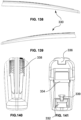
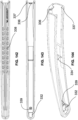
- Embodiments of a wiper blade assembly 10 and connection system are disclosed herein.
- Embodiments of a wiper blade assembly may be connectable with one or more wiper arm types 20 found on vehicles. Some of the many embodiments of wiper arm types 20 are shown in FIG. 153 .
- Wiper arm types may include one or more tongues, pins, hooks, or combinations thereof.
- a wiper blade assembly 10 may include a support structure 100, a wiper blade connector assembly 200, a wiper blade cover 300, and a wiper blade strip 400.
- any support structure 100 may be used with the disclosed concepts, including a traditional frame support structure, a beam support structure, a hybrid support structure having both traditional frames and beams or beam-like frames.
- the support structure 100 may include a primary frame 110, one or more secondary frames 130 connected to the primary frame 110, and one or more tertiary frames 150 each connected to a secondary frame 130.
- a primary frame 110 is connected with a secondary frame 130 on opposing longitudinal ends 10A, 10B using a secondary frame connector 120, and two tertiary frames 150 are connected with each secondary frame 130 on opposing longitudinal ends 10A, 10B using a tertiary frame connector 140.
- Each tertiary frame 150 may holds or support the wiper strip 400.
- the secondary frames may be modified to hold or support the wiper strip directly on one, or both, ends, in accordance with the disclosed concepts.
- a wiper blade cover 300 may be provided to cover or shield the majority of the support structure 100 from weather conditions.
- the wiper blade cover may be a single piece or, as shown in the illustrated embodiment, multi-sectional.
- a wiper blade connector assembly 200 may mutually connect with the support structure 100, on the one hand, and a wiper arm 20, on the other hand.
- the wiper blade connector assembly may include a wiper blade connector 210 and a wiper blade connector cover 230.
- the wiper blade connector assembly may be configured to connect to several different types of arms, and may form part of a connection system that includes one or more connector covers, and that may include an adapter.
- Persons of ordinary skill in the art will recognize that the disclosed concepts may be practiced with any connector, adapter or connection system known in the art or to be developed.
- Reference in the disclosure to a longitudinal direction is intended to refer to the direction coinciding with longitudinal ends 10A, 10B.
- Reference to the lateral direction is orthogonal to the longitudinal direction corresponding with the width of various components described herein.
- Top surfaces or ends correspond to the direction or side closer to, for instance, connector assembly 200 while bottom surfaces or ends correspond to the direction or side closer to, for instance, the wiper strip 400.
- Proximal ends or sides correspond to the direction closest to the portion of a wiper arm that connects to a vehicle.
- Distal ends or sides correspond to the direction or side furthest from the portion of a wiper arm that connects to a vehicle.
- Inner ends or sides correspond to the direction or side closest to the connector, primary rivet or center of a wiper blade.
- Outer ends or sides correspond to the direction or side furthest from the connector, primary rivet or center of the wiper blade.
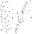
- support structure 100 may include a primary frame 110 which may be centrally provided within support structure 100.
- Primary frame 110 may be rigid.
- Primary frame 110 may include a central portion 111 and a pair of side portions 112 extending from central portion 111 in the longitudinal direction.
- Central portion 111 may include a pair of side walls 113, which may be parallel with respect to each other and orthogonal with the longitudinal direction of the wiper blade.
- Side portions 112 may each include a pair of side walls 113 and a top surface 114.
- the side walls 113 of the center portion 111 may positioned further laterally inward than the side walls 113 of the side portions 112.
- a narrower distance between the side walls 113 of the center portion 111 may facilitate rotation or rocking of a wiper blade connector assembly when connected with the primary frame 110.
- the width or distance between side walls 113 of the side portions 112 may be substantially similar to the width of a connector cover 230 and/or the width of the center section of wiper blade cover 300.
- the side walls 113 of the center portion 111 may be the same width as the side walls 113 of the side portions 112, such as the alternative embodiment shown in FIGS. 131-132 .
- the primary frame may be made out of any suitable material, including but not limited to metals, such as steel or aluminum, plastics, and other synthetic or composite materials.
- Primary frame holes 115 may be provided on the top side of the wide walls 113 of the center portion so as to engage with a rivet.
- Persons of ordinary skill in the art will recognize that the disclosed concepts may be practiced with any method or structure for connecting a wiper blade to a wiper arm known in the art or to be developed, including without limitation, direct connections to wiper arms, using inward projections or outward projections in place of a rivet, the holes, clips, or recesses receive projections or a rivet that is disposed on a connector, etc.
- Stops 116 may be provided on the top side of the side walls 113 of the center portion adjacent to primary frame holes which may prevent or otherwise control the degree of pivoting or rocking of a connected connector assembly 200.
- the side walls may be sloped from primary frame holes 115 towards the base of the side walls.
- rectangular side walls, or any other desired shape of side walls may be used in accordance with the disclosed concepts.
- Primary frame hole 115 may be positioned above the top surface 114 of side sections 112. Alternatively, primary hole 115 may be positioned in line with, or lower than the top surface 114 of side sections 112. In the illustrated embodiment, four total stops 116 are provided, two on each side wall 113 with one stop on each side of primary frame holes 115.
- One or more primary frame cover engagement structures may also be provided to facilitate engagement of primary frame 110 with wiper blade cover 300.
- Primary frame cover engagement projections 117 may be provided towards the bottom end side walls 113 on side portions 112 proximate or near center portion 111.
- Primary frame cover engagement projections 117 may be capable of engaging with a portion of cover 300, and as discussed further herein may be particularly capable of engaging with the center portion of a multi-sectional cover.
- Pivot extension walls 118 may be provided on the longitudinal ends of side portions 112. These pivot extension walls 118 may each include a primary-to-secondary hole 119 to facilitate engagement of a secondary frame connector, and holes 119 may be aligned so as to mutually receive a rivet, rod, or other cylindrical component as part of a secondary frame connector.
- primary frame 110 may be connected with a secondary frame 130 by a secondary frame connector 120.
- a secondary frame connector rivet 121 may be provided mutually through holes 119 of the primary frame 110 and a rivet passage 123 of a secondary connector structure 122 along a laterally defined secondary connector axis.
- Secondary frame connector 120 may include a base secondary connector structure 122 having one or more side openings 124 which may permit passage of a portion of secondary frame 130 there through. As shown and described in further detail herein, the portion of secondary frame 130 which may be disposed within secondary connector structure 122 may have a groove or valley 136 conformingly shaped with secondary frame connector rivet 121 and to further discourage separation of secondary connector structure 122 from secondary frame 130 once connected. Secondary connector structure 122 may be symmetrical about the secondary connector axis, and may thicker towards the center so as to accommodate the rivet 121 and the inserted portion of secondary frame 130. While primary frame 110 and secondary frame 130 are connected, the structure of secondary frame connector 120 may permit rocking or pivoting of secondary frame 130 with respect to primary frame 110 about the secondary connector axis. Extension walls 118 may be dimensioned and shaped so as to provide clearance of secondary connector structure 122 from the remainder of primary frame 110, including for instance top surface 114, so as to permit this rocking or pivoting.
- Secondary frame connector may be made out of plastic, or metal, or any other suitable material known in the art or to be developed.
- Secondary frame connector 120 may be a unitary structure, which may be molded around secondary frame 130.
- secondary frame connector may be assembled from multiple parts.
- secondary frame connector 120 may be formed from two secondary connector halves 120a by splitting the secondary connector frame along a vertical, longitudinal plane.
- Side openings 124 may lead to a passage formed between secondary connector half structure 122a and secondary connector half cylinder 128, which helps secure the valley 136 in the secondary frame.
- the secondary frame connector half may further include one or more projections 125, which may engage central holes 138 in the secondary frame.
- each secondary connector half 120a may be held together by a rivet 121, and/or or any other method of securing two secondary connector halves known in the art or to be developed, including but not limited to adhesives, being held together by the rivet within the extension walls 118 of the primary frame 110, projections that engage recesses, and other form-fit connections.
- a rivet 121 and/or or any other method of securing two secondary connector halves known in the art or to be developed, including but not limited to adhesives, being held together by the rivet within the extension walls 118 of the primary frame 110, projections that engage recesses, and other form-fit connections.
- other methods of forming secondary frame connectors may be practiced within the scope of the disclosed concepts.
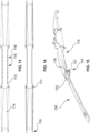
- a secondary frame 130 may include a first side portion 131, a second side portion 132, and a center portion 133.
- One or more side portions 131, 132 may be angled with respect to center portion 133, and in the illustrated embodiment first side portion 131 may be acutely angled downward from center portion 133, thereby forming an obtuse angle with same, while second side portion 132 may not be not angled.
- One or more side portions 131, 132 may further include one or more strengthening beads 134.
- a strengthening bead 134 be provided longitudinally along secondary frame 130.
- Three strengthening beads 134 are provided in the illustrated embodiment: a first bead 134A provide on the first portion 131 proximate to the longitudinal end 10A/10B; a second bead 134B provided on the first portion 131 as well as center portion 133, and spaced from first bead 134A; and a third bead 134C on second portion 132.
- Beads 134 may project or arc towards upwards from the top surface of the secondary frame 130.
- beads 134 On the underside, beads 134 may be hollow or recessed such that a uniform thickness is maintained across the secondary frame 134. By including beads 134, secondary frame may gain increased strength to resist failure from forces experienced by secondary frame 130 during operation of the wiper blade.
- One or more bead holes 135 may be provided in a strengthening bead 134.
- Center portion 133 may be partially curved into a valley 136 having a conforming shape with a secondary frame connector rivet 121.
- One or more central holes 138 may be disposed on either side of valley 136.
- Side portions 131, 132 may also include a tertiary connector hole 137.
- the tertiary connector hole 137 may be square, rectangular, oval, or any other suitable shape that is dimensioned and shaped to engage with a tertiary frame connector as described further herein.
- Side portions 131, 132 may be the same length or have different lengths, as shown in the illustrated embodiment where side portion 131 is longer than side portion 132.
- first side portion 131 may engage with wiper cover 300 as described further herein, and thus extending the length of side portion 131 may permit longer wiper blades and wiper blade covers.
- the secondary frames may be beam-like, and may be made from a resilient spring-elastic material, such as spring-elastic steel or other metals, or plastic.
- the secondary frames may be rigid, and made out of any suitable material including metals and plastics. Persons of skill in the art will recognize that different shapes and designs of the secondary frames or other secondary force distribution structures may be practiced in accordance with the disclosed concepts, including but not limited to rigid traditional frames, other beam-like frames, or in embodiments wherein the secondary frames are replaced by beams.
- FIG. 33 illustrates a cross sectional view of the secondary frame coupled to a secondary frame connector.
- FIGS. 34-37 illustrate an alternative embodiment of the secondary connector halves wherein the secondary frame connector 120 is split into halves structures 122a, 122b along a lateral, longitudinal plane. Internal projections 125 in each connector half 122a, 122b may engage both recesses 126 in the other half, and central holes 138 in the secondary frame. Additionally inner projections 127 may be provided in secondary connector half structure 122a to help secure valley 136 against the secondary connector half structure 122b.
- the disclosed concepts can be practices with any suitable design of a secondary frame connector currently known in the art or to be developed.
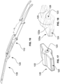
- one or more tertiary frames 150 may be each connected with a secondary frame 130 by a tertiary frame connector 140.
- two tertiary frames 150 are connected with secondary frame 130, one at each side portion 131, 132.
- the disclosure further contemplates just one tertiary frame 150 connected at either side portion 131, 132.
- Tertiary frame connector 140 may include a top portion 141, a bottom portion 142, and a neck portion 143 defined between the top and bottom portions.
- the neck portion 143 may be narrower than either top or bottom portions, and neck portion 143 may be dimensioned to fit within tertiary connector hole 137.
- Neck portion 143 may have a rounded outer surface to facilitate rocking or pivoting of a tertiary frame 150 with respect to secondary frame 130 about a tertiary pivot axis defined through tertiary connector hole 137.
- Top portion 141 may include a cap 144, which may have a substantially flat surface provided on the underside of cap which may contact a top surface of secondary frame 130.
- the cap 144 may be sized and shaped such that it may be inserted through the tertiary connector hole 137 in the secondary frame 130.
- the cap may further be sized and shaped such that when it is rotated 90 decrees relative to the secondary frame, the respective lateral sides of the cap are larger than the lateral sides of the tertiary connector hole 137, and thus the cap 144 helps secures the secondary frame 130 to the tertiary frame 150.
- Bottom portion 142 may include wings 145, which may be rounded or curved on their top surfaces which may contact the underside of tertiary frame 150.
- the bottom portion 142, including wings 145 may be sized and shaped such that they can be inserted into central tertiary connector hole 152 in the tertiary frame.
- the bottom portion 142, including wings 145 may be sized and shaped such when the tertiary connector 140 is rotated 90 degrees the distance between the ends of the wings 145 is greater than the distance between the lateral sides of the central hole 152 such that the wings help secure the tertiary frame 150 to the secondary frame 130.
- Any suitable frame connector capable of connecting the secondary frame to the tertiary frame including but not limited to the tertiary frame connectors described below with respect to FIGS. 55-60 , and all other tertiary frame connectors known in the art or to be developed may be used within the scope of the disclosed concepts.
- Tertiary frame connectors may be made out of any suitable material known in the art or to be developed, including but not limited to plastics and metals.
- a tertiary frame 150 may include tertiary side portions 151 and a center projecting from a central tertiary connector hole 152.
- the central tertiary connector hole 152 may be shaped to allow the bottom portion 142 of the secondary frame connector 140, to pass through in one orientation, and to secure it when the tertiary frame connector 140 is rotated 90 degrees.
- the central tertiary connector hole may have any suitable size and shape complementary to the size and shape of the tertiary frame connector.
- Side portions 51 may be acutely angled downward from central hole 152, thereby forming an obtuse angle with the opposing tertiary side portion.
- the respective side portions 151 may be symmetric, or may be asymmetric, both as to length and angle of descent. At or proximate to the longitudinal end of each side portion 151 may be a claw 153 dimensioned to grip a wiper strip 400.
- One or more beads 154 may also be provided on one or more side portions 151 similar to beads 134 provided on secondary frame 130.
- a side wall 155 may also be provided on lateral ends of tertiary frame 150 so as to block or shield the underside of tertiary frame 150 particularly near center hole 152 so as to protect the bottom portion 142 of tertiary connector 140.
- the side walls 155 may also increase the rigidity of the tertiary frame 150.
- the disclosed concepts may be practiced with tertiary frames may made out of any suitable material known in the art or to be developed, including but not limited to rigid and/or elastic metals and plastics.
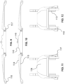
- FIGS. 55-60 illustrate alternative embodiments of tertiary connectors and/or holes 137, 152 for receiving same.
- an embodiment of a tertiary frame connector 140 may include a central gap 147 through neck portion 143 that may extend into either bottom portion (as shown for example in FIGS. 55 and 56 ) or top portion (as shown for example in FIGS. 57 and 58 ).
- the edges of central gap 147 may be defined by tertiary frame connector side walls 146, which may be elastically deflectable inward.
- wings 145 may project outward from side walls 146, or from a base, as shown in FIG. 57 .
- Wings 145 may project at an angle which may be acute (as shown for example in FIG. 55 ) or substantially perpendicular (as shown for example in FIG. 57 ). Wings 145 may be disposed adjacent to the bottom surface of secondary frame 130 as a tertiary frame 150 is connected with a secondary frame 130, such that they are sized and shaped to hold the tertiary frame 150 to the secondary frame 130.
- the cap 144 may be divided into separate portions which project outwardly from side walls 146 each of which has a substantially flat bottom surface which conformingly fits with the top surface of the secondary frame.
- the cap 144 have a substantially flat bottom surface to conformingly fit with the top side of secondary frame 130.
- Embodiments may include either one or two wings 145.
- tertiary frame connectors 140 such as those depicted in Figs. 55-58 may be inserted into holes 137, 152 such that the side walls are deflected inwardly until the wings 145 and/or cap 144 passes through the hole, and such that they snap into place once the wings 145 or cap 144 has passed through the holes 137, 152.
- the cap/wings may be inserted into holes 137, 152 and rotated into a securing position.
- the holes 137, 152 may be generally "T" shaped, and may further have a narrower neck between the top bar of the T and the bottom portion of the T.
- the wings 145 and/or cap 144 may be inserted into the top bar of the "T", and then slid into place, whereby the side walls 146 deflect enough to allow the tertiary connector to pass through the narrower neck into the bottom portion of the "T".
- Persons of skill in the art will recognize that any suitable combination of shapes and structures discussed herein may be combined and used within the scope of the disclosed concepts to securely connect frame to frame, whether primary, secondary or tertiary.
- an embodiment of tertiary frame connector 140 may include a cap 144 with one or more underside projections 144a. Underside projections 144a may secure tertiary frame connector 140 within tertiary connector hole 137 in secondary frame 130. As shown in the illustrated embodiment, a pair of underside cap projections 144a may be provided on opposing sides of neck portion 143, and cap projections 144a may be longitudinally oriented within tertiary connector hole 137 when inserted therein. Tertiary connector hole 137 may be sized and shaped to allow the bottom portion 142 of the tertiary frame connector 140, including the wings 145 to pass through in one orientation. The tertiary connector may then be rotated to fit the underside projections 144a within the tertiary connector hole 137, and the cap 144 may be sized such that it does not fit through the tertiary connector hole 137.
- a wiper blade connector assembly 200 may be provided to connect support structure 100, and more particularly to connect to with a wiper connector rivet 102 of a primary frame 110, with a plurality of types of wiper arms 20.
- Wiper blade connector assembly may include a wiper blade connector 210 and a wiper blade connector cover 230.
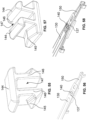
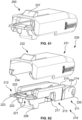
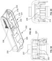
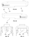
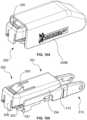
- Wiper blade connector cover 230 may be attached to the wiper blade connector 210 to assist with or facilitate securing a wiper arm 20 inserted between the wiper blade connector 210 and the connector cover 230 (shown more particularly in FIGS. 68-72 ).
- the pieces of the connector assembly 200 may be made out of plastic, or any other suitable material or materials known in the art by a person of skill in the art or to be developed. Additionally, a person of skill in the art will recognize that these connector assemblies are exemplary, and that the disclosed concepts can be practiced with any suitable connector assembly, including other connectors, adapters and connector covers.
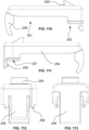
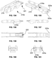
- Wiper blade connector 210 may include a first side portion 211, a second side portion 212, and center portion 213.
- the first side portion may be located on the distal end of the connector, while the second side portion may be located on the proximal end of the connector.
- a side wall 214 may be provided on each lateral edge of wiper blade connector 210 over one or more of each portion 211, 212, 213, and may include inner portions as well as outer portions.
- a pair of side walls 214 are provided along first side portion 211 and center portion 213.
- the top surface 215 of side walls 214 at first side portion 213 may be downwardly and acutely angled with respect to the top surface 215 of side walls 214 at central portion 213.
- the bottom surface 216 of side walls 214 may have varied elevations depending on the portion of the side walls 214. For instance, in the illustrated embodiment bottom surface 216 is positioned at a first elevation at first side portion 211 and center portion 213 proximate the first side portion, while bottom surface 216 of the outer side wall is positioned at a second, higher elevation at center portion 213 proximate the second side portion 212. Similarly, the bottom portion of the inner side wall is located at a lower elevation adjacent to a hook end stop 226. Between the first and second elevations of bottom surface 216 may be a rivet cutout 217 to accommodate an inserted wiper connector rivet 102.
- Rivet cutout 217 may extend laterally between side walls 214 adjacent to a rivet clip and a rivet passage disposed on the bottom of the center portion 222 of the connector.
- the rivet clip and rivet passage may form an "L" shape, and rivet 102 may be snap fit insertable therein.
- the inner surface of side wall 214 may include an inner ledge 218 including a primary frame stop cutout 219.
- stops 116 on primary frame 110 may be contactable with bottom surface 216 at the second side portion 212, while stops 116 adjacent to the first side portion 211 may be contactable with stop cutouts 219 to prevent over rocking of connector 210.
- stop cutouts 219 may be provided in the second side portion.
- connector cover receiving structures such as connector cover receiving holes 220 or recesses may be provided on each side wall 214.
- Each connector cover hole 220 may be engageable with a connector hole rod 232 provided on an inner surface of connector cover 230.
- a shelf 221 may be provided with having a center section 222 and lateral wings 223. Reinforcing ribs may be located there between along the top surface of the shelf 221.
- internal side walls 214 may form reinforcing ribs underneath the bottom surface of the shelf 221.
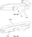
- the center portion 222 of the shelf 221 may be integrated with the lateral wings 223, as shown in FIGs. 61-82 , or the center portion may be cantilevered and capable of moving relative to the lateral wings 223, as shown in FIGs. 126-130 and discussed below.
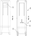
- Connector cover tabs 234 may be provided on an inner surface of connector cover 230, and connector cover tabs 234 may be engageable by snap-fit with lateral wings 223, as shown in FIG. 61 . Alternatively, this relationship may be swapped, with claws or projections on the connector 210 engaging holes, recesses or shelves on the connector cover within the scope of the disclosed concepts.
- Connector cover 230 may rotate about a connector cover axis extending laterally through connector cover holes 220. In an open position, connector cover 230 may accommodate the insertion of a wiper arm 20 into connector 210, and then be rotated downward into a closed position to secure the inserted wiper arm 20 with the connector cover 230 locking into the closed position by engagement of tabs 234 with wings 220.
- One or more side walls may also include an outward protrusion 224 positioned on the central portion 213 proximate the first side portion 211.
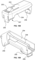
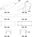
- Connector cover 230 may include a first portion 231 and a second portion 232 defined at longitudinally opposed ends. The first portion may be located on the distal end of the connector, while the second portion may be located on the proximal end of the connector.
- a pair of the aforementioned connector hole rods 233 may be provided on opposing inner surfaces in the first portion 231, with each rod 233 projecting inwardly so as to engage hole 220. As previously discussed, this relationship may be swapped, or any other suitable connection method known in the art may be used.
- a pair of the aforementioned connector cover tabs 234 may be provided on the second portion 232. As previously discussed, this relationship may be swapped, or any other suitable connection method known in the art may be used.
- Connector cover 230 may further include a bottom edge 235.
- the bottom edge 235 may have a first, lower elevation at the first portion 231 of the connector cover 230, and a second, higher elevation, at the second portion 232.
- the change in elevation may be made at 90 degree angles such that it acts as a stop for claws 23 of a wiper arm 20.
- Embodiments of connector cover 230 are generally shown and described herein as substantially covering the length of embodiments of connector 210 in a locked or secured position. However, embodiments where connector cover 230 only covers a significantly smaller portion of connector 210 are contemplated within the disclosure. For example, connector cover tabs 234 may engaged with first portion 211 of connector 210 rather than second portion 212 as generally shown and described. An example of this shorter connector cover embodiment is shown as Figure 13 in U.S. Prov. Patent No. 62/538,368 .
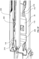
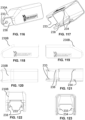
- Wiper arms 20 having hooks 21 may be connected with wiper blade connector assembly 200 by placing the connector cover 230 in an open position, inserting the hook end of the wiper arm 20 into the connector 210, pulling the wiper arm 20 so that until it snuggly fits into a connector channel 225 and the end of the hook contacts a hook end stop 226 on the bottom side of connector 210, and rotating connector cover 230 into its closed position.
- On the underside surface of connector cover 230 may be a hook stop 236 to further secure the curved end of the hook type warm in when connector cover 230 is in the closed position.
- connector assembly 200 may also be connected with wiper arms 20 having openings 22 and/or underside ledges 23.
- a resilient button 237 may be provided on the top surface of connector cover 230. Button 237 may protrude upwards and be provided on a cantilever on the top surface of connector cover 230.
- a wiper arm 20 may engage with connector cover 230 by having button 237 inserted into opening 22 while underside ledges 23 are fit underneath the bottom surface 235, which may be the portion of bottom surface 235 with a higher elevation on the second portion 232.
- the button 237 may have a chamfered top surface to facilitate engaging with the opening 22.
- an embodiment of connector assembly 200 may include an embodiment of connector cover 230A connectable with connector 210.
- Connector cover 230A may be longer than connector cover 230.
- connector 210 may include two different types of wings 223 as part of shelf 221. Wings may include a first wing 223A longitudinally projecting first distance, while a second wing 223B may longitudinally project a second distance further than first. Additionally, a first wing 223 may have a rounded corner, while a second wing 223B may have a more rectangular corner.
- Connector cover 230A may also include one or more inner platforms 238 provided on the inner surface of connector cover 230A at or proximate first end 231, which increase the thickness of the connector cover side walls. Rods 233 may project from the platforms 238.
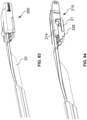
- FIGS. 93-96 illustrate various types of wiper arms 20 connected with a wiper blade connector assembly 200 including a wiper blade connector 210 and a wiper blade connector cover 230A.
- FIGS. 94 and 95 illustrate a wiper arm 20 having a wing members 24 and a front tongue 25.
- Connector cover tabs 234 may be conformingly dimensioned secure wing members 24 while front tongue 25 may be positionable between cover 230A and connector 210.
- the wiper arm may fit over connector 210 and between connector side walls 214 and cover 230A, and wiper arm 20 may press against the edge of platform 238.
- FIG. 95 illustrates how a wiper arm 20 having a rear tongue 25 may be accommodated, such that rear tongue 25 may be insertable within channel 225.
- a wiper blade connector assembly may include a wiper blade connector 210, and wiper blade connector cover 230B, and a wiper blade connector adapter 250 connected between connector 210 and connector cover 230B.
- Connector cover 230B may be taller than connector cover 230A.
- Adapter 250 may include a first portion 251 and a second portion 252, a top surface 253 and a pair of side walls 254. The first portion 251 may be located on the distal end of the adapter 250 while the second portion 252 may be located on the proximal end of the adapter 250 .
- An adapter button 255 may project from or be connected with top surface 253 from a cantilever.
- Adapter side walls 254 may include a bottom edge 256 which may have a staggered or different elevations.
- bottom edge 256 has a higher elevation over first portion 251 than it does over second portion 252.
- the lower elevation bottom edge 256 may include a cutout 257 to accommodate a projection from a wiper arm 20 as shown further herein.
- the higher elevation of bottom edge 256 may contact the upper edge 215 of connector 210, while the slower elevation of bottom edge 256 may contact the top side of shelf 221, and more particularly the top side of wings 223.
- one side of the top surface of the proximal end of the adapter 250 may be more curved, while the other end may be more rectangular. This may facilitate connections with arms that have the engagement portion offset such as wiper arm 20 shown in FIG. 124 .
- a first clip 258 may be provided at the first portion 251 of adapter 250, and a second clip 259 may be provided at second portion 252.
- First clip 258 may project downwards and snap fit against the curved area, where a wiper arm hook 21 may fit as previously shown, of connector 210 proximate rivet cutout 217.
- Second clip 259 may also project downwards and clip the underside of shelf 221 at center section 222.
- One or both of the first clip 258 and second clip 259 may be elastically deflectable to facilitate connection of the adapter 250 to the connector 210.
- FIGS. 124 and 125 show an embodiment of wiper blade connector assembly 200 having adapter 250 and connector cover 230B connected with a wiper arm 20 having opening 22.
- Cover tabs 234 may grip the edge of arm 22 in the closed position, and tab 255 may engage the opening 22 in the wiper arm,.
- wiper adapter 250 may allow connector assembly 200 to accommodate differently dimensioned wiper As 20, including those that are larger or thicker.
- Use of adapter 250 may require a differently dimensioned cover 350B at least having longer side walls.
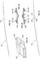
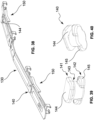
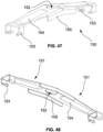
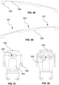
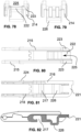
- an embodiment of connector assembly 200 may include a connector 210A having a pillar 227 which may project upwardly from shelf 221 between wings 223. Pillar 227 may be cantilevered 228 to an upper lip 229 which may be resiliently engageable with a tongue on wiper arm 20, as described further herein. The lip 229 may be sized and shaped to engage with the rear tongue 25 of a wiper arm. Pillar 227 may an extension of hook end stop 226, which collectively may be a bent cantilever extending from the center of connector 210A proximate rivet cutout 217. Moreover, connector 210A shows that a rivet window 217A may be used in place of a rivet cutout 217.
- a rivet window 217A may be provided adjacent to the rivet passage and rivet clip, and rivet window may not extend through lower edge 216.
- Cover 230A may also be provided with rear tabs 234A to press-fit connect with the lower edge 216 of side wall 214, potentially at protrusion 224.
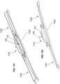
- FIG. 131 and 132 shows another embodiment of primary frame 110 whereby the mounting base 111A is a separate piece from the rest of primary frame 110.
- Mounting base 111A may be securely attached to primary frame 110 via welding, crimping, or any other method known to a person of ordinary skill in the art.
- Mounting base 111A may have a lower profile and may be engaged at its longitudinal edges with adjacent side portions 112A, and side portions 112A may have adjoining side walls 113A which removal central portion 111A sits between.
- Wiper blade cover 300 may be provided to cover various components of the wiper blade, particularly support structure 100, from environmental conditions.
- Wiper blade cover 300 may include a center section 310 and two side sections 330.
- Center section may include side walls 312 between two wrap over portions 313 which extend over the central portion 111 of primary frame 110 at the longitudinal edges of center section 310.
- the cover center section may preferably be made of a rigid, or hard plastic, while the cover side sections may be preferably made from a rigid, hard plastic or an elastic, soft plastic.
- Persons of skill in the art will recognize that the disclosed concepts may include covers made from any suitable material or materials known in the art or to be developed, including but not limited to plastics, rubbers, and silicone.
- One or more ribs 314 may be provided on the inner surface of the center section 310.
- One or more ribs 316 may be provided along the bottom edge of side walls 312 to engage with the underside of side walls 113 of the primary frame 110 to facilitate the securing of center section 310 to same.
- the grips 316 may be provided on the end of ribs 314 on the inner side of side walls 312. Persons of skill in the art will recognize that the grips 316 described herein are exemplary and that any structure for connecting and securing the cover center section 310 to the primary frame 110 may be used.
- Center section side walls 312 may also have a recessed area 315 so as not to interfere with the rocking or pivoting of a connected connector assembly 200.
- Inner ledge 317 may have a downwardly sloped section 318 descending at an acute angle adjacent the recessed area 315.
- the downwardly sloped section 318 may further have a narrow portion 319 such that the distance between the outer surfaces of the sidewall 112 at the narrow portion 319 is less than the distance between the outer surfaces of sidewalls 312 at other portions of the cover center section 310.
- Side sections 330 may include an outer end groove 332 dimensioned to receive an outer end of a secondary frame 150.
- Outer groove 332 may be defined by a ledge provided on the bottom side of side section cover 330, with the ledge projecting inwardly throughout the distal end. The outer edge of a secondary frame 150 may then fit on that ledge.
- Inner projections 339 may be provided to engage holes in on the outer end of secondary frame, such as bead hole 135.
- One or more intermediary braces 334 may also be provided within side section 330 to provide lateral support, and to secure the support structure 100, such as primary frame 110.
- a downward projection 336 may be provided on the underside of the side section 330 proximate the center section 310 to engage the inner edge of the primary frame side portions 112, and to reduce gaps between the wiper blade cover sections 310, 330 as the wiper blade moves and the sections 310, 330 may be forced apart.
- At or proximate to the center section 310 may be one or more holes 337 to receive cover engagements 117 on primary frame 110.
- the inner surface of the side wall of cover side section 330 may be recessed adjacent to holes 337 to facilitate insertion of cover engagements 117.
- Tire treading 338 may also be provided on an upper surface of side sections which may dually serve an ornamental purpose as well as an aerodynamic purpose as the wiper blade moves.
- the cover may be provided with a spoiler, or any other functional or aesthetic features known in the art or to be developed, within the scope of the disclosed concepts.
- a spoiler or any other functional or aesthetic features known in the art or to be developed, within the scope of the disclosed concepts.
- Persons of skill in the art will recognize that the cover design illustrated in these figures is exemplary and that the disclosed concepts may be practiced with any suitable cover known in the art or to be developed.
- FIGS. 154-171 further embodiments of a connector assembly 200 are shown and described including a connector 210b, connector cover 230c, and adapter 250a.
- FIGS. 154-161 illustrate an embodiment of a connector 210b which includes a shelf opening or window 222a provided on the center portion 222 of shelf 221.
- One or more notches 223a may be provided on shelf 222, and more particularly on wings 223.
- the one or more notches 223a may have a substantially triangular cross section.
- the positioning and dimensioning of notches 223a may receive the ends of projections on or claws having a generally triangular or bent shape and may improve the secure interface with corresponding latches on certain embodiments of a wiper arm 20.
- a bottom edge slot 216a may also be provided to receive, and further secure, certain embodiments of a wiper arm 20.
- a primary frame stop cutout 219 may further be disposed further inward, i.e., closer to the pivot point, and corresponding adjustments may be made to the positioning of stops 116.
- FIGS. 162-169 illustrate an embodiment of a connector cover 230c.
- Connector cover tabs 234b may include cutouts 239 to accommodate wiper arm claws or projections having a generally triangular or bent shape.
- Connector cover 230c may further have triangular shaped supports on the lower side of tabs 234b to increase support and facilitate securing the cover to the wiper arm.
- An underside wall may also be provided to abut portions of either a connector or adapter.
- FIGS. 170 and 171 illustrate an embodiment of an adapter 250a.
- Embodiments of adapter 250, 250a may include clips 258, 259 which may be inward facing, as illustrated in previous embodiments, or outward facing, as second clip 259 is shown in adapter 250a.
- an outward facing second clip 259 may engage with the shelf window 222a of connector 210b.
- An end stop 260 may also be provided at the end of either first or second portion 251, 252. As shown, an end stop 260 is provided at first portion 251 proximate first clip 258. End stop 260 may longitudinally project past first clip 258, may curl upwards towards top surface 253, and may include a top wall 261 projecting away from top surface 253 proximate the end of first portion 251.
- Top wall 261 may press or abut against underside wall on cover 230b, and may receive, abut, or otherwise act as a stop for an end of a wiper arm 20. Additionally, adapter 250a may be provided with stop wall 262 which may also receive, abut, or otherwise act as a stop for an end of a wiper arm. The cutouts 257 in adapter 250a may further be provided with stops 263 that receive, abut, or otherwise act as stop for the projections or claws of a wiper arm 20.
- the primary frame stop cutout 219 may be provided at the bottom surface of side walls 214 rather than on an inner ledge.
- wings 223 may extend from a longitudinal projection off side walls 214a rather than from a shelf 221. Wings 223 may also contact a portion of lower edges 26 on side walls of a wiper arm 20.
- connector cover 230 may cover a significantly smaller portion of connector 210 are contemplated within the disclosure.
- connector cover tabs 234 may engaged with first portion 211 of connector 210 rather than second portion 212 as generally shown and described.
- An upper tab 236a may project from the underside and engage with a front tongue 24 of a wiper arm.
Landscapes
- Engineering & Computer Science (AREA)
- Mechanical Engineering (AREA)
- General Engineering & Computer Science (AREA)
- Connector Housings Or Holding Contact Members (AREA)
Claims (17)
- Wischerblatt-Verbinderbaugruppe (200) zum Verbinden einer Wischerblatt-Tragestruktur (100) mit einem Wischerarm (20), wobei die Wischerblatt-Verbinderbaugruppe Folgendes umfasst:einen Wischerblattverbinder (210), der einen ersten Abschnitt (211), einen zweiten Abschnitt (212) in Längsrichtung gegenüber dem ersten Abschnitt und einen mittleren Abschnitt (213) aufweist, der zwischen dem ersten und dem zweiten Abschnitt definiert ist, wobei der Wischerblattverbinder Folgendes beinhaltet:ein Paar Seitenwandungen (214), die sich zumindest über einen Teil des ersten, zweiten und mittleren Abschnitts erstrecken, wobei jede Seitenwandung eine obere Fläche (215) und eine untere Fläche (216) umfasst,einen Verbinderkanal (225), der zwischen dem Paar Seitenwandungen an dem zweiten Abschnitt des Wischerblattverbinders definiert ist, wobei der Verbinderkanal dafür bemessen ist, mindestens einen Abschnitt des Wischerarms unterzubringen,eine Nietenaussparung (217), die nahe der unteren Fläche bereitgestellt und dafür bemessen ist, eine Niete an der Wischerblatt-Tragestruktur unterzubringen, undein Hakenendanschlag (226), der nahe der unteren Fläche bereitgestellt und von der Nietenaussparung beabstandet ist, wobei der Hakenendanschlag derart positioniert ist, dass er an dem Ende eines hakenartigen Wischerarms anliegt,dadurch gekennzeichnet, dass die Wischerblatt-Verbinderbaugruppe ferner einer Wischerblattverbinder-Abdeckung (230) umfasst, die einen ersten Abschnitt (231) und einen zweiten Abschnitt (232) aufweist, der dem ersten Abschnitt in Längsrichtung gegenüberliegt, wobei der erste Abschnitt (231) der Wischerblattverbinder-Abdeckung in Bezug auf den ersten Abschnitt (211) des Wischerblattverbinders schwenkbar ist und der zweite Abschnitt (232) der Wischerblattverbinder-Abdeckung an dem Wischerblattverbinder gesichert werden kann, und
einen Wischerblattverbinder-Adapter (250), der einen ersten Abschnitt (251) und einen zweiten Abschnitt (252) aufweist, der dem ersten Abschnitt in Längsrichtung gegenüberliegt, wobei der Wischerblattverbinder-Adapter zwischen dem Wischerblattverbinder und der Wischerblattverbinder-Abdeckung gesichert werden kann. - Wischerblatt-Verbinderbaugruppe nach Anspruch 1, wobei die obere Fläche der Seitenwandungen an dem ersten Abschnitt in Bezug auf die obere Fläche an dem mittleren Abschnitt nach unten abgewinkelt ist und die obere Fläche der Seitenwände an dem mittleren Abschnitt koplanar mit dem oberen Abschnitt der Seitenwände an dem zweiten Abschnitt liegt.
- Wischerblatt-Verbinderbaugruppe nach Anspruch 2, wobei eine Innenseite mindestens einer Seitenwandung an dem ersten Abschnitt einen inneren Absatz beinhaltet und der innere Absatz eine primäre Rahmenaussparung beinhaltet.
- Wischerblatt-Verbinderbaugruppe nach Anspruch 2, wobei die untere Fläche der Seitenwandungen an dem ersten Abschnitt koplanar mit der unteren Fläche der Seitenwandungen an dem mittleren Abschnitt liegt.
- Wischerblatt-Verbinderbaugruppe nach Anspruch 4, wobei die untere Fläche der Seitenwandungen an dem mittleren Abschnitt auf einer anderen Höhe liegt als die untere Fläche der Seitenwandungen an dem zweiten Abschnitt.
- Wischerblatt-Verbinderbaugruppe nach Anspruch 5, wobei die Nietenaussparung nahe der Mitte und zweiter Abschnitte bereitgestellt ist und der Hakenendanschlag an dem zweiten Abschnitt bereitgestellt ist.
- Wischerblatt-Verbinderbaugruppe nach Anspruch 1, wobei die Nietenaussparung eine Nietenklemme und einen Nietendurchlass beinhaltet, der eine L-Form bildet.
- Wischerblatt-Verbinderbaugruppe nach Anspruch 1, wobei der Wischerblattverbinder ferner ein Fach (221) beinhaltet, das an dem zweiten Abschnitt des Wischerblattverbinders bereitgestellt ist, wobei das Fach einen mittleren Teilabschnitt (222) beinhaltet, der an dem Verbinderkanal ausgerichtet ist, und mindestens einen Flügel (223), der nahe einer der Seitenwandungen (214) bereitgestellt ist, und
wobei die Wischerblattverbinder-Abdeckung mindestens eine Verbinderabdeckungsnase (234) beinhaltet, die an dem zweiten Abschnitt der Wischerblattverbinder-Abdeckung bereitgestellt ist, und die mindestens eine Verbinderabdeckungsnase mit dem mindestens einen Flügel in Eingriff gebracht werden kann, um die Wischerblattverbinder-Abdeckung in einer geschlossenen Position zu sichern. - Wischerblatt-Verbinderbaugruppe nach Anspruch 8, wobei die obere Fläche der Seitenwandungen an dem ersten Abschnitt des Wischerblattverbinders in Bezug auf die obere Fläche der Seitenwandungen an dem mittleren Abschnitt des Wischerblattverbinders nach unten abgewinkelt ist und die obere Fläche der Seitenwandungen an dem Mittelabschnitt des Wischerblattverbinders koplanar zu dem oberen Abschnitt der Seitenwandungen an dem zweiten Abschnitt des Wischerblattverbinders liegt,wobei die untere Fläche der Seitenwandungen an dem ersten Abschnitt des Wischerblattverbinders koplanar mit der unteren Fläche der Seitenwandungen an dem mittleren Abschnitt des Wischerblattverbinders liegt und die untere Fläche der Seitenwandungen an dem mittleren Abschnitt des Wischerblattverbinders auf einer anderen Höhe liegt als die untere Fläche der Seitenwandungen an dem zweiten Abschnitt des Wischerblattverbinders undwobei eine Unterseite des mindestens einen Flügels koplanar mit der unteren Fläche der Seitenwandungen an dem zweiten Abschnitt des Wischerblattverbinders liegt.
- Wischerblatt-Verbinderbaugruppe nach Anspruch 8, wobei die Wischerblattverbinder-Abdeckung ferner mindestens eine hintere Abdeckungsnase (234A) beinhaltet, die an dem ersten Abschnitt der Wischerblattverbinder-Abdeckung bereitgestellt ist, und wobei der Wischerblattverbinder ferner einen nach außen gerichteten Vorsprung (224) beinhaltet, der sich von einer Außenfläche einer der Verbinderseitenwandungen (214) aus erstreckt,
wobei die mindestens eine hintere Abdeckungsnase mit einer unteren Seite des Vorsprungs in Eingriff gebracht werden kann, wenn sich die Abdeckung in der geschlossenen Position befindet. - Wischerblatt-Verbinderbaugruppe nach Anspruch 1, wobei der erste Abschnitt des Wischerblattverbinders ein Paar Verbinderabdeckungs-Aufnahmeöffnungen (220) beinhaltet und der erste Abschnitt der Wischerblattverbinder-Abdeckung ein Paar Verbinderöffnungsstäbe (233) beinhaltet, die nach innen hervorstehen und mit den Verbinderabdeckungs-Aufnahmeöffnungen in Eingriff gebracht werden können.
- Wischerblatt-Verbinderbaugruppe nach Anspruch 1, wobei eine Unterseite der Wischerblattverbinder-Abdeckung einen Hakenanschlag (236) beinhaltet.
- Wischerblatt-Verbinderbaugruppe nach Anspruch 1, wobei die Wischerblattverbinder-Abdeckung eine untere Fläche (235) auf einer ersten Höhe an dem ersten Abschnitt der Wischerblattverbinder-Abdeckung und auf einer zweiten Höhe an dem zweiten Abschnitt der Wischerblattverbinder-Abdeckung beinhaltet.
- Wischerblatt-Verbinderbaugruppe nach Anspruch 1, wobei die Wischerblattverbinder-Abdeckung einen Drücker (237) beinhaltet, der an einer oberen Fläche der Wischerblattverbinder-Abdeckung auskragt und eine ferne Kante des Drückers von der oberen Fläche der Wischerblattverbinder-Abdeckung nach oben aufragt und eine abgeschrägte Fläche beinhaltet.
- Wischerblatt-Verbinderbaugruppe nach Anspruch 1, wobei der Wischerblattverbinder ferner ein Fach (221) beinhaltet, das an dem zweiten Abschnitt des Wischerblattverbinders bereitgestellt ist, wobei das Fach einen mittleren Teilabschnitt (222) beinhaltet, der an dem Verbinderkanal ausgerichtet ist, und mindestens einen Flügel (223), der nahe einer der Seitenwandungen (214) bereitgestellt ist,wobei der Wischerblattverbinder-Adapter eine erste Klammer (251) beinhaltet, die an dem ersten Abschnitt des Wischerblattverbinder-Adapters bereitgestellt ist, und eine zweite Klammer (252), die an dem zweiten Abschnitt des Wischerblattverbinder-Adapters bereitgestellt ist,wobei die erste Klammer durch den Verbinderkanal eingeführt werden kann und eine ferne Kante der zweiten Klammer mit einer Unterseite des mittleren Teilabschnitts des Fachs in Eingriff gebracht werden kann undwobei die Wischerblattverbinder-Abdeckung mindestens eine Verbinderabdeckungsnase (234) beinhaltet, die an dem zweiten Abschnitt der Wischerblattverbinder-Abdeckung bereitgestellt ist, und die mindestens eine Verbinderabdeckungsnase mit dem mindestens einen Flügel in Eingriff gebracht werden kann, um die Wischerblattverbinder-Abdeckung in einer geschlossenen Position zu sichern.
- Wischerblatt-Verbinderbaugruppe nach Anspruch 1, wobei der Wischerblattverbinder-Adapter Adapterseitenwandungen (254) beinhaltet, die eine untere Kante (256) aufweisen, die an mindestens einem Teil des zweiten Abschnitts des Wischerblattverbinders in Kontakt mit der oberen Fläche der Verbinderseitenwandungen steht.
- Wischerblatt-Baugruppe (10), verbindbar mit einem Wischerarm (20), wobei die Wischerblatt-Baugruppe Folgendes umfasst:eine Tragestruktur (100) undeine Wischerblatt-Verbinderbaugruppe (200) nach Anspruch 1 zum Verbinden der Tragestruktur (100) mit dem Wischerarm (20).
Applications Claiming Priority (7)
| Application Number | Priority Date | Filing Date | Title |
|---|---|---|---|
| US201762538368P | 2017-07-28 | 2017-07-28 | |
| US201762587111P | 2017-11-16 | 2017-11-16 | |
| US201862625335P | 2018-02-01 | 2018-02-01 | |
| US201862646498P | 2018-03-22 | 2018-03-22 | |
| US201862651435P | 2018-04-02 | 2018-04-02 | |
| US201862671539P | 2018-05-15 | 2018-05-15 | |
| PCT/US2018/044423 WO2019023711A1 (en) | 2017-07-28 | 2018-07-30 | CONNECTION AND WIPER ASSEMBLY |
Publications (3)
| Publication Number | Publication Date |
|---|---|
| EP3658426A1 EP3658426A1 (de) | 2020-06-03 |
| EP3658426A4 EP3658426A4 (de) | 2021-04-07 |
| EP3658426B1 true EP3658426B1 (de) | 2023-10-18 |
Family
ID=65040394
Family Applications (1)
| Application Number | Title | Priority Date | Filing Date |
|---|---|---|---|
| EP18838787.2A Active EP3658426B1 (de) | 2017-07-28 | 2018-07-30 | Anordnung eines scheibenwischerblattverbinders |
Country Status (9)
| Country | Link |
|---|---|
| US (2) | US11370394B2 (de) |
| EP (1) | EP3658426B1 (de) |
| JP (1) | JP7133621B2 (de) |
| KR (1) | KR20200037321A (de) |
| CN (1) | CN111051154B (de) |
| AU (2) | AU2018308154A1 (de) |
| CA (1) | CA3070567A1 (de) |
| ES (1) | ES2971496T3 (de) |
| WO (1) | WO2019023711A1 (de) |
Families Citing this family (2)
| Publication number | Priority date | Publication date | Assignee | Title |
|---|---|---|---|---|
| US11370394B2 (en) * | 2017-07-28 | 2022-06-28 | Pylon Manufacturing Corporation | Windshield wiper connector and assembly |
| KR102741282B1 (ko) | 2020-05-07 | 2024-12-11 | 주식회사 쏠리드 | 스펙트럼 공유 시스템과 연동하는 분산 안테나 시스템 및 그 운영 방법 |
Family Cites Families (84)
| Publication number | Priority date | Publication date | Assignee | Title |
|---|---|---|---|---|
| US2600292A (en) * | 1948-09-25 | 1952-06-10 | Gen Electric | Frequency discriminator circuit |
| US3072756A (en) * | 1960-01-29 | 1963-01-08 | Tabet Mfg Company Inc | Electrical switch assembly |
| FR2441517A1 (fr) * | 1978-11-15 | 1980-06-13 | Champion Spark Plug Co | Dispositif d'attache d'un balai d'essuie-glace a son bras d'entrainement |
| FR2486476A3 (fr) * | 1980-07-10 | 1982-01-15 | Arman Spa | Dispositif d'attache d'un balai d'essuie-glace a son bras d'entrainement |
| FR2560839B1 (fr) * | 1984-03-06 | 1986-09-19 | Journee Paul Sa | Attache pour balai d'esuie-glace |
| FR2600292B1 (fr) * | 1986-06-20 | 1990-02-23 | Marchal Equip Auto | Dispositif d'attache reliant un bras d'essuie-glace et un etrier portant une lame racleuse |
| US5289608A (en) * | 1991-10-29 | 1994-03-01 | Alberee Product Inc. | Windshield wiper frame connector which accomodates different size wiper arms |
| FR2736025B1 (fr) * | 1995-06-28 | 1997-08-01 | Valeo Systemes Dessuyage | Essuie-glace pour vehicule automobile comportant un connecteur muni d'un capot articule |
| FR2786449B1 (fr) * | 1998-11-30 | 2001-02-23 | Valeo Systemes Dessuyage | Connecteur d'essuie-glace de vehicule automobile |
| JP2001163188A (ja) * | 1999-09-30 | 2001-06-19 | Ngk Spark Plug Co Ltd | ワイパーブレード連結具 |
| JP2002356143A (ja) | 2001-05-31 | 2002-12-10 | Jidosha Denki Kogyo Co Ltd | ワイパアーム |
| EP1359073B1 (de) | 2002-05-03 | 2006-07-12 | Federal-Mogul S.A. | Scheibenwischervorrichtung |
| DE50309219D1 (de) | 2002-11-26 | 2008-04-03 | Valeo Wischersysteme Gmbh | Vorrichtung zum lösbaren verbinden eines wischblatts mit einem antreibbaren wischarm |
| US7207082B2 (en) * | 2002-12-27 | 2007-04-24 | Albert Lee | Windshield wiper frame connector which accommodates different size wiper arms |
| FR2879987B1 (fr) | 2004-12-23 | 2007-03-09 | Valeo Systemes Dessuyage | Support de liaison de balai d'essuie-glace plat |
| CA2541641C (en) | 2005-04-04 | 2014-02-11 | Trico Products Corporation | Wiper coupler and wiper assembly incorporating same |
| CA2590443C (en) * | 2006-10-12 | 2012-01-17 | Adm21 Co., Ltd. | Adaptor of wiper blade |
| DE102008027566A1 (de) * | 2008-06-10 | 2009-12-17 | Valeo Systèmes d'Essuyage | Wischblatt sowie Wischarm |
| US8286298B2 (en) | 2008-07-11 | 2012-10-16 | Adm21 Co., Ltd. | Device for connecting a flat wiper blade to wiper arms |
| DE102008041996A1 (de) * | 2008-09-11 | 2010-03-18 | Robert Bosch Gmbh | Vorrichtung zum gelenkigen Verbinden eines Wischblatts mit einem Wischarm eines Scheibenwischers |
| DE102008049269B4 (de) | 2008-09-26 | 2020-08-27 | Valeo Systèmes d'Essuyage | Wischarm/Wischblatt-Verbindung sowie Wischblatt |
| DE102008049273A1 (de) * | 2008-09-26 | 2010-04-01 | Valeo Systèmes d'Essuyage | Wischblatt sowie Wischblatt/Wischarmverbindung |
| JP5476468B2 (ja) * | 2009-07-10 | 2014-04-23 | フェデラル−モーグル コーポレイション | 多機能のワイパーブレードコネクタおよびアセンブリ |
| DE102010007557A1 (de) | 2010-02-10 | 2011-08-11 | Valeo Wischersysteme GmbH, 74321 | Wischvorrichtung für Fahrzeugscheiben und Wischblatt mit einer Heizeinrichtung |
| HUE028461T2 (en) | 2010-04-22 | 2016-12-28 | Federal Mogul Sa | Wiper tool |
| US8261403B2 (en) | 2010-05-13 | 2012-09-11 | Trico Products Corporation | Beam blade windshield wiper assembly |
| US8397341B2 (en) | 2010-05-13 | 2013-03-19 | Trico Products Corporation | Beam blade windshield wiper assembly |
| CN101863265B (zh) | 2010-06-17 | 2013-10-09 | 东莞鸿益雨刷有限公司 | 雨刷连接组件和雨刷组合 |
| FR2962092B1 (fr) | 2010-06-30 | 2013-06-28 | Valeo Systemes Dessuyage | Adaptateur d'essuie-glace a contacts electriques |
| DE102010025687A1 (de) | 2010-06-30 | 2012-01-05 | Valeo Wischersysteme Gmbh | Wischblatt zum Reinigen von Fahrzeugscheiben |
| KR101170905B1 (ko) | 2010-09-10 | 2012-08-06 | 김인규 | 후크 와이퍼 아암용 연결유닛 및 이를 구비한 플랫 와이퍼 블레이드 |
| CN102001327B (zh) | 2010-11-19 | 2012-10-10 | 殷小恒 | 一种雨刮器 |
| WO2012090638A1 (ja) | 2010-12-27 | 2012-07-05 | 株式会社ミツバ | ワイパブレードおよびその組付け方法 |
| CN102582582A (zh) | 2011-01-14 | 2012-07-18 | 东莞鸿益雨刷有限公司 | 雨刷 |
| CN201998951U (zh) | 2011-01-20 | 2011-10-05 | 程宝来 | 一种雨刮器中的雨刮臂接头 |
| CN102653269A (zh) | 2011-03-04 | 2012-09-05 | 东莞鸿益雨刷有限公司 | 雨刷臂连接器及雨刷 |
| DE102011005171A1 (de) | 2011-03-07 | 2012-09-13 | Robert Bosch Gmbh | Wischblattadaptervorrichtung, insbesondere für eine Kraftfahrzeugscheibenwischvorrichtung |
| US10322699B2 (en) | 2011-07-29 | 2019-06-18 | Pylon Manufacturing Corp. | Windshield wiper connector |
| CN202193060U (zh) | 2011-08-24 | 2012-04-18 | 宁波鑫海爱多汽车雨刷制造有限公司 | 雨刷及其接头 |
| US9481343B2 (en) | 2011-12-14 | 2016-11-01 | Federal-Mogul Corporation | Windscreen wiper device |
| US8997304B2 (en) | 2011-12-14 | 2015-04-07 | Federal-Mogul Corporation | Windscreen wiper device |
| KR101147826B1 (ko) * | 2011-12-20 | 2012-05-18 | (주)에이치 에스 티 | 와이퍼 암 체결용 커넥터 장치 |
| CN104125899B (zh) | 2011-12-29 | 2016-08-31 | 费德罗-莫格尔公司 | 挡风玻璃的雨刮器装置 |
| KR101350277B1 (ko) * | 2012-01-27 | 2014-01-14 | 케이씨더블류 주식회사 | 플랫 와이퍼 블레이드 및 플랫 와이퍼 블레이드 조립체 |
| WO2013126910A1 (en) | 2012-02-24 | 2013-08-29 | Pylon Manufacturing Corp. | Hinged wiper blade |
| RU2577981C1 (ru) * | 2012-02-24 | 2016-03-20 | Пилон Мануфэкчуринг Корп. | Щетка стеклоочистителя |
| CN104349950A (zh) * | 2012-06-13 | 2015-02-11 | 罗伯特·博世有限公司 | 刮水片适配器系统 |
| US9145111B2 (en) | 2012-09-10 | 2015-09-29 | Alberee Products, Inc. | Hybrid blade |
| CN202863398U (zh) | 2012-09-12 | 2013-04-10 | 东莞鸿益雨刷有限公司 | 雨刷与雨刷杆的装配结构 |
| US9925957B2 (en) | 2012-12-11 | 2018-03-27 | Qinghuai Shen | Windscreen wiper strip support and windscreen wiper blade having same |
| KR101245363B1 (ko) * | 2013-01-24 | 2013-03-19 | 동양기전 주식회사 | 오조립 방지 구조가 구비된 와이퍼 블레이드 장치 |
| US9555775B2 (en) * | 2013-03-15 | 2017-01-31 | Illinois Tool Works Inc. | Connectors and connector kit for attachment of a windshield wiper blade to multiple types of windshield wiper arms |
| KR20150141186A (ko) | 2013-04-12 | 2015-12-17 | 페더럴-모걸 코오포레이숀 | 윈드스크린 와이퍼 장치 |
| FR3005443B1 (fr) | 2013-05-13 | 2017-09-08 | Valeo Systemes Dessuyage | Interface de connexion hydraulique et/ou electrique pour balai d'essuie-glace. |
| FR3005441B1 (fr) | 2013-05-13 | 2015-05-29 | Valeo Systemes Dessuyage | Interface de connexion hydraulique et/ou electrique pour balai d’essuie-glace |
| FR3005446B1 (fr) | 2013-05-13 | 2015-07-03 | Valeo Systemes Dessuyage | Ensemble pour la realisation d'un systeme d'essuyage de pare brise de vehicule automobile et dispositif de connexion comprenant un tel ensemble |
| FR3005442B1 (fr) | 2013-05-13 | 2015-05-29 | Valeo Systemes Dessuyage | Dispositif de fixation d'essuie-glace et systeme d'essuyage comprenant ledit dispositif de fixation |
| DE102013104902A1 (de) | 2013-05-13 | 2014-11-13 | Valeo Systèmes d'Essuyage | Wischarm für eine Scheibenwischanlage eines Kraftfahrzeugs, Wischblatt und Wischeinrichtung |
| FR3006964B1 (fr) | 2013-06-12 | 2017-04-21 | Valeo Systemes Dessuyage | Ensemble d'une tete de bras et d'un adaptateur pour un systeme d'essuyage de pare brise, adaptateur et tete de bras correspondants et systeme d'essuyage obtenu |
| FR3008053B1 (fr) | 2013-07-08 | 2015-08-28 | Valeo Systemes Dessuyage | Connecteur entre un balai d'essuyage et un bras d'entrainement de systeme d'essuyage |
| FR3011211B1 (fr) | 2013-09-30 | 2017-01-13 | Valeo Systemes Dessuyage | Connecteur ou adaptateur pour systeme d'essuyage d'un pare-brise, notamment de vehicule automobile |
| CN104648329B (zh) | 2013-11-19 | 2017-04-12 | 扬弘实业股份有限公司 | 刮水器用连接器及其刮水器组件 |
| DE102013019805B4 (de) | 2013-11-27 | 2022-06-15 | Mercedes-Benz Group AG | Verbindungsanordnung zum Verbinden eines Wischblatts mit einem Wischarm, sowie Wischblatt und Wischarm zur Herstellung einer solchen Verbindungsanordnung |
| US9505380B2 (en) * | 2014-03-07 | 2016-11-29 | Pylon Manufacturing Corp. | Windshield wiper connector and assembly |
| CN106507671B (zh) | 2014-05-13 | 2019-05-14 | 费德罗-莫格尔汽车配件有限责任公司 | 挡风玻璃雨刷器装置 |
| EP3164304B1 (de) | 2014-07-03 | 2018-06-13 | Federal-Mogul S.a. | Scheibenwischervorrichtung |
| EP3461702B1 (de) | 2014-08-08 | 2020-08-12 | Mitsuba Corporation | Wischervorrichtung und düseneinheit |
| CN204506837U (zh) | 2015-03-24 | 2015-07-29 | 美途汽配实业(厦门)有限公司 | 滑盖式新型雨刷连接器 |
| CN204488738U (zh) * | 2015-03-24 | 2015-07-22 | 美途汽配实业(厦门)有限公司 | 多功能雨刷臂连接器 |
| KR101691427B1 (ko) | 2015-04-17 | 2017-01-09 | 앨버리 프로덕츠 인코포레이티드 | 윈드쉴드 와이퍼 어셈블리 |
| KR101691426B1 (ko) | 2015-04-17 | 2016-12-30 | 앨버리 프로덕츠 인코포레이티드 | 윈드쉴드 와이퍼 어셈블리 |
| FR3037897B1 (fr) | 2015-06-26 | 2018-11-02 | Valeo Systemes D'essuyage | Adaptateur pour un essuie-glace de vehicule automobile et ensemble comportant un tel adaptateur |
| US11273797B2 (en) | 2015-10-14 | 2022-03-15 | Trico Belgium S.a. | Windscreen wiper device |
| FR3043042B1 (fr) | 2015-11-04 | 2017-12-15 | Valeo Systemes Dessuyage | Adaptateur pour un essuie-glace de vehicule automobile |
| FR3043041B1 (fr) * | 2015-11-04 | 2017-12-08 | Valeo Systemes Dessuyage | Adaptateur pour un essuie-glace de vehicule automobile |
| EP3452341B1 (de) | 2016-05-02 | 2020-05-06 | Federal-Mogul S.a. | Fahrzeug mit mindestens zwei scheibenwischvorrichtungen mit flachem blatt |
| AU2017268019A1 (en) | 2016-05-19 | 2018-11-22 | Pylon Manufacturing Corp. | Windshield wiper connector |
| CN109311452A (zh) | 2016-05-19 | 2019-02-05 | 电缆塔制造有限公司 | 挡风玻璃雨刮器连接器 |
| US20170334407A1 (en) | 2016-05-19 | 2017-11-23 | Pylon Manufacturing Corporation | Windshield wiper connector |
| FR3056511B1 (fr) | 2016-09-29 | 2022-01-14 | Valeo Systemes Dessuyage | Adaptateur constitutif d'un systeme d'essuyage |
| FR3056510B1 (fr) | 2016-09-29 | 2021-10-15 | Valeo Systemes Dessuyage | Adaptateur pour la connexion d'un balai d'essuyage a un bras d'entrainement d'un systeme d'essuyage pour vehicule automobile |
| FR3056512A1 (fr) | 2016-09-29 | 2018-03-30 | Valeo Systemes D'essuyage | Adaptateur constitutif d'un systeme d'essuyage |
| US10150452B2 (en) | 2016-10-14 | 2018-12-11 | Federal-Mogul Motorparts Llc | Windscreen wiper device |
| US11370394B2 (en) * | 2017-07-28 | 2022-06-28 | Pylon Manufacturing Corporation | Windshield wiper connector and assembly |
-
2018
- 2018-07-30 US US16/049,540 patent/US11370394B2/en active Active
- 2018-07-30 EP EP18838787.2A patent/EP3658426B1/de active Active
- 2018-07-30 CN CN201880058324.7A patent/CN111051154B/zh active Active
- 2018-07-30 CA CA3070567A patent/CA3070567A1/en active Pending
- 2018-07-30 KR KR1020207005889A patent/KR20200037321A/ko not_active Ceased
- 2018-07-30 JP JP2020527864A patent/JP7133621B2/ja active Active
- 2018-07-30 AU AU2018308154A patent/AU2018308154A1/en not_active Abandoned
- 2018-07-30 ES ES18838787T patent/ES2971496T3/es active Active
- 2018-07-30 WO PCT/US2018/044423 patent/WO2019023711A1/en not_active Ceased
-
2022
- 2022-06-27 US US17/850,861 patent/US11780408B2/en active Active
-
2024
- 2024-08-30 AU AU2024216465A patent/AU2024216465A1/en not_active Abandoned
Also Published As
| Publication number | Publication date |
|---|---|
| JP2020529946A (ja) | 2020-10-15 |
| US20220402461A1 (en) | 2022-12-22 |
| US20190031153A1 (en) | 2019-01-31 |
| US11370394B2 (en) | 2022-06-28 |
| US11780408B2 (en) | 2023-10-10 |
| CA3070567A1 (en) | 2019-01-31 |
| CN111051154B (zh) | 2023-09-12 |
| AU2024216465A1 (en) | 2024-09-19 |
| WO2019023711A1 (en) | 2019-01-31 |
| JP7133621B2 (ja) | 2022-09-08 |
| AU2018308154A1 (en) | 2020-02-06 |
| EP3658426A1 (de) | 2020-06-03 |
| CN111051154A (zh) | 2020-04-21 |
| KR20200037321A (ko) | 2020-04-08 |
| EP3658426A4 (de) | 2021-04-07 |
| ES2971496T3 (es) | 2024-06-05 |
Similar Documents
| Publication | Publication Date | Title |
|---|---|---|
| AU2024216465A1 (en) | Windshield wiper connector and assembly | |
| US10661759B2 (en) | Windshield wiper connector | |
| US11273796B2 (en) | Windshield wiper blade | |
| US8484794B2 (en) | Device for the articulated connection of a wiper blade to a wiper arm of a windshield wiper | |
| US4547925A (en) | Carrier for a windscreen wiper blade | |
| AU2023200078A1 (en) | Windshield wiper connector | |
| US20110239396A1 (en) | Windscreen wiper device | |
| JPS6220927B2 (de) | ||
| MX2014010123A (es) | Escobilla limpiaparabrisas. | |
| WO2008045195A1 (en) | Airbag assembly mounting system | |
| EP3710316B1 (de) | Scheibenwischerverbinder und anordnung | |
| US11760312B2 (en) | Windshield wiper blade | |
| CN107826083B (zh) | 一种适用于u型刮臂的雨刷连接器及雨刷 | |
| EP0285379B1 (de) | Bügel oder Hebel für Scheibenwischerblattgestell | |
| GB2278270A (en) | Windscreen wiper blade with airfoil | |
| US20220024418A1 (en) | Windshield wiper connector |
Legal Events
| Date | Code | Title | Description |
|---|---|---|---|
| STAA | Information on the status of an ep patent application or granted ep patent |
Free format text: STATUS: THE INTERNATIONAL PUBLICATION HAS BEEN MADE |
|
| PUAI | Public reference made under article 153(3) epc to a published international application that has entered the european phase |
Free format text: ORIGINAL CODE: 0009012 |
|
| STAA | Information on the status of an ep patent application or granted ep patent |
Free format text: STATUS: REQUEST FOR EXAMINATION WAS MADE |
|
| 17P | Request for examination filed |
Effective date: 20200218 |
|
| AK | Designated contracting states |
Kind code of ref document: A1 Designated state(s): AL AT BE BG CH CY CZ DE DK EE ES FI FR GB GR HR HU IE IS IT LI LT LU LV MC MK MT NL NO PL PT RO RS SE SI SK SM TR |
|
| AX | Request for extension of the european patent |
Extension state: BA ME |
|
| DAV | Request for validation of the european patent (deleted) | ||
| DAX | Request for extension of the european patent (deleted) | ||
| A4 | Supplementary search report drawn up and despatched |
Effective date: 20210310 |
|
| RIC1 | Information provided on ipc code assigned before grant |
Ipc: B60S 1/42 20060101ALI20210303BHEP Ipc: B60S 1/04 20060101ALI20210303BHEP Ipc: B60S 1/40 20060101AFI20210303BHEP Ipc: B60S 1/38 20060101ALI20210303BHEP |
|
| STAA | Information on the status of an ep patent application or granted ep patent |
Free format text: STATUS: EXAMINATION IS IN PROGRESS |
|
| 17Q | First examination report despatched |
Effective date: 20220707 |
|
| GRAP | Despatch of communication of intention to grant a patent |
Free format text: ORIGINAL CODE: EPIDOSNIGR1 |
|
| STAA | Information on the status of an ep patent application or granted ep patent |
Free format text: STATUS: GRANT OF PATENT IS INTENDED |
|
| INTG | Intention to grant announced |
Effective date: 20230511 |
|
| P01 | Opt-out of the competence of the unified patent court (upc) registered |
Effective date: 20230711 |
|
| GRAS | Grant fee paid |
Free format text: ORIGINAL CODE: EPIDOSNIGR3 |
|
| GRAA | (expected) grant |
Free format text: ORIGINAL CODE: 0009210 |
|
| STAA | Information on the status of an ep patent application or granted ep patent |
Free format text: STATUS: THE PATENT HAS BEEN GRANTED |
|
| AK | Designated contracting states |
Kind code of ref document: B1 Designated state(s): AL AT BE BG CH CY CZ DE DK EE ES FI FR GB GR HR HU IE IS IT LI LT LU LV MC MK MT NL NO PL PT RO RS SE SI SK SM TR |
|
| REG | Reference to a national code |
Ref country code: GB Ref legal event code: FG4D |
|
| REG | Reference to a national code |
Ref country code: CH Ref legal event code: EP |
|
| REG | Reference to a national code |
Ref country code: IE Ref legal event code: FG4D |
|
| REG | Reference to a national code |
Ref country code: DE Ref legal event code: R096 Ref document number: 602018059708 Country of ref document: DE |
|
| REG | Reference to a national code |
Ref country code: LT Ref legal event code: MG9D |
|
| REG | Reference to a national code |
Ref country code: NL Ref legal event code: MP Effective date: 20231018 |
|
| REG | Reference to a national code |
Ref country code: AT Ref legal event code: MK05 Ref document number: 1622180 Country of ref document: AT Kind code of ref document: T Effective date: 20231018 |
|
| PG25 | Lapsed in a contracting state [announced via postgrant information from national office to epo] |
Ref country code: NL Free format text: LAPSE BECAUSE OF FAILURE TO SUBMIT A TRANSLATION OF THE DESCRIPTION OR TO PAY THE FEE WITHIN THE PRESCRIBED TIME-LIMIT Effective date: 20231018 |
|
| PG25 | Lapsed in a contracting state [announced via postgrant information from national office to epo] |
Ref country code: GR Free format text: LAPSE BECAUSE OF FAILURE TO SUBMIT A TRANSLATION OF THE DESCRIPTION OR TO PAY THE FEE WITHIN THE PRESCRIBED TIME-LIMIT Effective date: 20240119 |
|
| PG25 | Lapsed in a contracting state [announced via postgrant information from national office to epo] |
Ref country code: IS Free format text: LAPSE BECAUSE OF FAILURE TO SUBMIT A TRANSLATION OF THE DESCRIPTION OR TO PAY THE FEE WITHIN THE PRESCRIBED TIME-LIMIT Effective date: 20240218 |
|
| PG25 | Lapsed in a contracting state [announced via postgrant information from national office to epo] |
Ref country code: LT Free format text: LAPSE BECAUSE OF FAILURE TO SUBMIT A TRANSLATION OF THE DESCRIPTION OR TO PAY THE FEE WITHIN THE PRESCRIBED TIME-LIMIT Effective date: 20231018 |
|
| PG25 | Lapsed in a contracting state [announced via postgrant information from national office to epo] |
Ref country code: AT Free format text: LAPSE BECAUSE OF FAILURE TO SUBMIT A TRANSLATION OF THE DESCRIPTION OR TO PAY THE FEE WITHIN THE PRESCRIBED TIME-LIMIT Effective date: 20231018 |
|
| PG25 | Lapsed in a contracting state [announced via postgrant information from national office to epo] |
Ref country code: LT Free format text: LAPSE BECAUSE OF FAILURE TO SUBMIT A TRANSLATION OF THE DESCRIPTION OR TO PAY THE FEE WITHIN THE PRESCRIBED TIME-LIMIT Effective date: 20231018 Ref country code: IS Free format text: LAPSE BECAUSE OF FAILURE TO SUBMIT A TRANSLATION OF THE DESCRIPTION OR TO PAY THE FEE WITHIN THE PRESCRIBED TIME-LIMIT Effective date: 20240218 Ref country code: GR Free format text: LAPSE BECAUSE OF FAILURE TO SUBMIT A TRANSLATION OF THE DESCRIPTION OR TO PAY THE FEE WITHIN THE PRESCRIBED TIME-LIMIT Effective date: 20240119 Ref country code: BG Free format text: LAPSE BECAUSE OF FAILURE TO SUBMIT A TRANSLATION OF THE DESCRIPTION OR TO PAY THE FEE WITHIN THE PRESCRIBED TIME-LIMIT Effective date: 20240118 Ref country code: AT Free format text: LAPSE BECAUSE OF FAILURE TO SUBMIT A TRANSLATION OF THE DESCRIPTION OR TO PAY THE FEE WITHIN THE PRESCRIBED TIME-LIMIT Effective date: 20231018 Ref country code: PT Free format text: LAPSE BECAUSE OF FAILURE TO SUBMIT A TRANSLATION OF THE DESCRIPTION OR TO PAY THE FEE WITHIN THE PRESCRIBED TIME-LIMIT Effective date: 20240219 |
|
| PG25 | Lapsed in a contracting state [announced via postgrant information from national office to epo] |
Ref country code: SE Free format text: LAPSE BECAUSE OF FAILURE TO SUBMIT A TRANSLATION OF THE DESCRIPTION OR TO PAY THE FEE WITHIN THE PRESCRIBED TIME-LIMIT Effective date: 20231018 Ref country code: RS Free format text: LAPSE BECAUSE OF FAILURE TO SUBMIT A TRANSLATION OF THE DESCRIPTION OR TO PAY THE FEE WITHIN THE PRESCRIBED TIME-LIMIT Effective date: 20231018 Ref country code: PL Free format text: LAPSE BECAUSE OF FAILURE TO SUBMIT A TRANSLATION OF THE DESCRIPTION OR TO PAY THE FEE WITHIN THE PRESCRIBED TIME-LIMIT Effective date: 20231018 Ref country code: NO Free format text: LAPSE BECAUSE OF FAILURE TO SUBMIT A TRANSLATION OF THE DESCRIPTION OR TO PAY THE FEE WITHIN THE PRESCRIBED TIME-LIMIT Effective date: 20240118 Ref country code: LV Free format text: LAPSE BECAUSE OF FAILURE TO SUBMIT A TRANSLATION OF THE DESCRIPTION OR TO PAY THE FEE WITHIN THE PRESCRIBED TIME-LIMIT Effective date: 20231018 Ref country code: HR Free format text: LAPSE BECAUSE OF FAILURE TO SUBMIT A TRANSLATION OF THE DESCRIPTION OR TO PAY THE FEE WITHIN THE PRESCRIBED TIME-LIMIT Effective date: 20231018 |
|
| REG | Reference to a national code |
Ref country code: ES Ref legal event code: FG2A Ref document number: 2971496 Country of ref document: ES Kind code of ref document: T3 Effective date: 20240605 |
|
| PG25 | Lapsed in a contracting state [announced via postgrant information from national office to epo] |
Ref country code: DK Free format text: LAPSE BECAUSE OF FAILURE TO SUBMIT A TRANSLATION OF THE DESCRIPTION OR TO PAY THE FEE WITHIN THE PRESCRIBED TIME-LIMIT Effective date: 20231018 |
|
| REG | Reference to a national code |
Ref country code: DE Ref legal event code: R097 Ref document number: 602018059708 Country of ref document: DE |
|
| PG25 | Lapsed in a contracting state [announced via postgrant information from national office to epo] |
Ref country code: CZ Free format text: LAPSE BECAUSE OF FAILURE TO SUBMIT A TRANSLATION OF THE DESCRIPTION OR TO PAY THE FEE WITHIN THE PRESCRIBED TIME-LIMIT Effective date: 20231018 |
|
| PG25 | Lapsed in a contracting state [announced via postgrant information from national office to epo] |
Ref country code: SK Free format text: LAPSE BECAUSE OF FAILURE TO SUBMIT A TRANSLATION OF THE DESCRIPTION OR TO PAY THE FEE WITHIN THE PRESCRIBED TIME-LIMIT Effective date: 20231018 |
|
| PG25 | Lapsed in a contracting state [announced via postgrant information from national office to epo] |
Ref country code: SM Free format text: LAPSE BECAUSE OF FAILURE TO SUBMIT A TRANSLATION OF THE DESCRIPTION OR TO PAY THE FEE WITHIN THE PRESCRIBED TIME-LIMIT Effective date: 20231018 Ref country code: SK Free format text: LAPSE BECAUSE OF FAILURE TO SUBMIT A TRANSLATION OF THE DESCRIPTION OR TO PAY THE FEE WITHIN THE PRESCRIBED TIME-LIMIT Effective date: 20231018 Ref country code: RO Free format text: LAPSE BECAUSE OF FAILURE TO SUBMIT A TRANSLATION OF THE DESCRIPTION OR TO PAY THE FEE WITHIN THE PRESCRIBED TIME-LIMIT Effective date: 20231018 Ref country code: IT Free format text: LAPSE BECAUSE OF FAILURE TO SUBMIT A TRANSLATION OF THE DESCRIPTION OR TO PAY THE FEE WITHIN THE PRESCRIBED TIME-LIMIT Effective date: 20231018 Ref country code: EE Free format text: LAPSE BECAUSE OF FAILURE TO SUBMIT A TRANSLATION OF THE DESCRIPTION OR TO PAY THE FEE WITHIN THE PRESCRIBED TIME-LIMIT Effective date: 20231018 Ref country code: DK Free format text: LAPSE BECAUSE OF FAILURE TO SUBMIT A TRANSLATION OF THE DESCRIPTION OR TO PAY THE FEE WITHIN THE PRESCRIBED TIME-LIMIT Effective date: 20231018 Ref country code: CZ Free format text: LAPSE BECAUSE OF FAILURE TO SUBMIT A TRANSLATION OF THE DESCRIPTION OR TO PAY THE FEE WITHIN THE PRESCRIBED TIME-LIMIT Effective date: 20231018 |
|
| PLBE | No opposition filed within time limit |
Free format text: ORIGINAL CODE: 0009261 |
|
| STAA | Information on the status of an ep patent application or granted ep patent |
Free format text: STATUS: NO OPPOSITION FILED WITHIN TIME LIMIT |
|
| 26N | No opposition filed |
Effective date: 20240719 |
|
| PG25 | Lapsed in a contracting state [announced via postgrant information from national office to epo] |
Ref country code: SI Free format text: LAPSE BECAUSE OF FAILURE TO SUBMIT A TRANSLATION OF THE DESCRIPTION OR TO PAY THE FEE WITHIN THE PRESCRIBED TIME-LIMIT Effective date: 20231018 |
|
| PG25 | Lapsed in a contracting state [announced via postgrant information from national office to epo] |
Ref country code: SI Free format text: LAPSE BECAUSE OF FAILURE TO SUBMIT A TRANSLATION OF THE DESCRIPTION OR TO PAY THE FEE WITHIN THE PRESCRIBED TIME-LIMIT Effective date: 20231018 |
|
| PGFP | Annual fee paid to national office [announced via postgrant information from national office to epo] |
Ref country code: LU Payment date: 20250728 Year of fee payment: 8 |
|
| PG25 | Lapsed in a contracting state [announced via postgrant information from national office to epo] |
Ref country code: FI Free format text: LAPSE BECAUSE OF FAILURE TO SUBMIT A TRANSLATION OF THE DESCRIPTION OR TO PAY THE FEE WITHIN THE PRESCRIBED TIME-LIMIT Effective date: 20231019 |
|
| PGFP | Annual fee paid to national office [announced via postgrant information from national office to epo] |
Ref country code: ES Payment date: 20250801 Year of fee payment: 8 |
|
| PGFP | Annual fee paid to national office [announced via postgrant information from national office to epo] |
Ref country code: DE Payment date: 20250729 Year of fee payment: 8 |
|
| PGFP | Annual fee paid to national office [announced via postgrant information from national office to epo] |
Ref country code: MC Payment date: 20250707 Year of fee payment: 8 |
|
| PGFP | Annual fee paid to national office [announced via postgrant information from national office to epo] |
Ref country code: BE Payment date: 20250728 Year of fee payment: 8 Ref country code: GB Payment date: 20250728 Year of fee payment: 8 |
|
| PGFP | Annual fee paid to national office [announced via postgrant information from national office to epo] |
Ref country code: FR Payment date: 20250728 Year of fee payment: 8 |
|
| PGFP | Annual fee paid to national office [announced via postgrant information from national office to epo] |
Ref country code: CH Payment date: 20250801 Year of fee payment: 8 |
|
| PGFP | Annual fee paid to national office [announced via postgrant information from national office to epo] |
Ref country code: IE Payment date: 20250728 Year of fee payment: 8 |
|
| PG25 | Lapsed in a contracting state [announced via postgrant information from national office to epo] |
Ref country code: CY Free format text: LAPSE BECAUSE OF FAILURE TO SUBMIT A TRANSLATION OF THE DESCRIPTION OR TO PAY THE FEE WITHIN THE PRESCRIBED TIME-LIMIT; INVALID AB INITIO Effective date: 20180730 |
|
| PG25 | Lapsed in a contracting state [announced via postgrant information from national office to epo] |
Ref country code: HU Free format text: LAPSE BECAUSE OF FAILURE TO SUBMIT A TRANSLATION OF THE DESCRIPTION OR TO PAY THE FEE WITHIN THE PRESCRIBED TIME-LIMIT; INVALID AB INITIO Effective date: 20180730 |