EP3658447B1 - Support pour valises latérales d'une motocyclette - Google Patents
Support pour valises latérales d'une motocyclette Download PDFInfo
- Publication number
- EP3658447B1 EP3658447B1 EP18731826.6A EP18731826A EP3658447B1 EP 3658447 B1 EP3658447 B1 EP 3658447B1 EP 18731826 A EP18731826 A EP 18731826A EP 3658447 B1 EP3658447 B1 EP 3658447B1
- Authority
- EP
- European Patent Office
- Prior art keywords
- carrier element
- vehicle frame
- motorcycle
- vehicle
- connecting arrangement
- Prior art date
- Legal status (The legal status is an assumption and is not a legal conclusion. Google has not performed a legal analysis and makes no representation as to the accuracy of the status listed.)
- Active
Links
Images




Classifications
-
- B—PERFORMING OPERATIONS; TRANSPORTING
- B62—LAND VEHICLES FOR TRAVELLING OTHERWISE THAN ON RAILS
- B62J—CYCLE SADDLES OR SEATS; AUXILIARY DEVICES OR ACCESSORIES SPECIALLY ADAPTED TO CYCLES AND NOT OTHERWISE PROVIDED FOR, e.g. ARTICLE CARRIERS OR CYCLE PROTECTORS
- B62J9/00—Containers specially adapted for cycles, e.g. panniers or saddle bags
- B62J9/20—Containers specially adapted for cycles, e.g. panniers or saddle bags attached to the cycle as accessories
- B62J9/24—Containers specially adapted for cycles, e.g. panniers or saddle bags attached to the cycle as accessories on specially adapted racks, e.g. for top or side cases
-
- B—PERFORMING OPERATIONS; TRANSPORTING
- B62—LAND VEHICLES FOR TRAVELLING OTHERWISE THAN ON RAILS
- B62J—CYCLE SADDLES OR SEATS; AUXILIARY DEVICES OR ACCESSORIES SPECIALLY ADAPTED TO CYCLES AND NOT OTHERWISE PROVIDED FOR, e.g. ARTICLE CARRIERS OR CYCLE PROTECTORS
- B62J7/00—Luggage carriers
- B62J7/02—Luggage carriers characterised by the arrangement thereof on cycles
- B62J7/04—Luggage carriers characterised by the arrangement thereof on cycles arranged above or behind the rear wheel
-
- B—PERFORMING OPERATIONS; TRANSPORTING
- B62—LAND VEHICLES FOR TRAVELLING OTHERWISE THAN ON RAILS
- B62J—CYCLE SADDLES OR SEATS; AUXILIARY DEVICES OR ACCESSORIES SPECIALLY ADAPTED TO CYCLES AND NOT OTHERWISE PROVIDED FOR, e.g. ARTICLE CARRIERS OR CYCLE PROTECTORS
- B62J9/00—Containers specially adapted for cycles, e.g. panniers or saddle bags
- B62J9/20—Containers specially adapted for cycles, e.g. panniers or saddle bags attached to the cycle as accessories
- B62J9/23—Containers specially adapted for cycles, e.g. panniers or saddle bags attached to the cycle as accessories above or alongside the rear wheel
Definitions
- the invention relates to a connection arrangement for fastening lateral luggage containers to a motorcycle or a motorcycle-like vehicle, according to the preamble of claim 1, and a correspondingly equipped motorcycle or motorcycle-like vehicle according to the preamble of claim 12.
- these lateral luggage containers in particular when loaded with luggage, can promote or increase the motorcycle's tendency to pendulum. Therefore, great efforts are usually made in the vehicle to such To reduce the tendency to swing, for example through complex adjustments to the chassis or through complex luggage rack systems.
- the latter can according to the US 9,010,598 B2 comprise a parallelogram-like substructure to which the side luggage containers are attached.
- the movable mounting poses a structural challenge compared to the overall vehicle, in particular with regard to a coordination between the intended vibration-damping effect and sufficient strength for a stable and resilient connection.
- the carrier element is connected to the vehicle frame section so as to be movable relative to the latter and the carrier element in the area of the left and right end each comprises a lateral support arm and two cross members connecting the lateral support arms, the two lateral support arms each for Connect to the respective associated lateral luggage container, the carrier element being designed as a frame element, the lateral support arms being connected to one another at their ends by a cross member.
- the connection arrangement thus provides a vehicle frame section which, when installed on the vehicle (motorcycle or motorcycle-like vehicle), is usually connected to a structure or to a (remaining) vehicle frame of the motor vehicle.
- the vehicle frame section can, for example, form a rear section of the vehicle frame in the area of a rear wheel and define an essentially horizontally oriented section. This can be arranged below a seat or a bench in the vertical direction of the vehicle.
- the vehicle frame section can be designed to support at least part of the seat or a seat bench.
- the carrier element is connected to the vehicle frame section in such a way that the carrier element extends at least in its transverse direction and a relative movement of the carrier element with respect to the vehicle frame section is also possible.
- the transverse direction is oriented transversely to the longitudinal direction of the vehicle frame section, that is to say in a width direction of the vehicle frame section.
- the carrier element is connected at both ends to one of the two luggage containers. These can therefore be arranged, for example, on a left or a right side of the vehicle frame section.
- the longitudinal direction of the vehicle frame section preferably corresponds to a longitudinal direction of the motor vehicle itself.
- the carrier element can be arranged on an upper side of the vehicle frame section and fastened in a relatively movable manner.
- the carrier element is positioned above the vehicle frame section in the vehicle height direction. If there is a seat or a bench in this area, the carrier element can also be arranged below the seat or the bench, that is to say in the vertical direction between the vehicle frame section and the seat / bench.
- the carrier element is arranged on an underside of the vehicle frame section and is fastened to it in a relatively movable manner.
- the carrier element can also be arranged within the vehicle frame section and extend through it.
- Luggage containers are, for example, side cases or side bags that are or will be connected to the respective ends of the carrier element.
- the respective connection is preferably designed as a detachable connection, if necessary, in order to remove the respective luggage container from the motor vehicle, as will be described in detail below.
- the carrier element comprises a lateral support arm and two cross members connecting the lateral support arms to one another, the two lateral supports Support arms are each designed to be connected to the respective associated lateral luggage container.
- the lateral support arms can be aligned parallel and laterally spaced apart from a central axis oriented in the longitudinal direction or essentially parallel spaced apart from one side of the vehicle frame section.
- the cross members can be aligned in the transverse direction of the vehicle frame section in order to connect the two lateral support arms to one another.
- a U- or double-T-shaped carrier element can thus be produced when using a single cross member (viewed in a plan view).
- two cross members are provided.
- this offers the possibility of designing the support element as a frame element, in particular as a rectangular or trapezoidal frame element, the lateral support arms being connected to one another at their ends by one of the cross members.
- the design of the carrier element as a frame element enables the provision of a self-contained frame which has an advantageously increased rigidity, in particular an increased torsional rigidity.
- the carrier element can optionally be manufactured as a one-piece component. This can be done through a one-piece production or through a material connection of several separately produced individual parts, such as, for example, by welding the lateral support arms to the one or more cross members.
- Said relative movement can for example be defined by a translational movement transversely to the longitudinal direction of the vehicle frame section being.
- This means that the carrier element can be moved longitudinally in the transverse direction relative to the vehicle frame section and thus also transversely to the entire motor vehicle.
- a range of movement y in the range of -20 mm y +20 mm, preferably 10 mm y +10 mm, particularly preferably -7 mm y +7 mm can be provided.
- the carrier element connected to the vehicle frame section can optionally be shifted from a central neutral position by a maximum of 20 mm or a maximum of 10 mm or a maximum of 7 mm in the direction of the left side or in the direction of the right side. In this way, an effective decoupling of movements is provided, so that pendulum movements of the vehicle can be damped.
- the carrier element can be connected to the vehicle frame section in a translationally movable manner via a number of bearing points, for example, the bearing points each having a guide section for guiding the translational movement.
- the bearing points can have elongated holes or guide grooves which serve as guide sections for corresponding connecting pins which connect the carrier element to the vehicle frame section.
- the connecting pins are preferably firmly connected to the vehicle frame section and the guide sections are assigned to the carrier element or are formed in it. Of course, the reverse arrangement is also possible.
- the elongated holes are preferably transverse to the longitudinal direction of the vehicle frame section and thus in the transverse direction described extends to guide the correspondingly oriented relative movement.
- a respective length of the guide sections is matched to the intended scope of movement, so that the guide sections have at least the corresponding length or are selected to be longer. If they have the same length, the respective ends of the guide sections can be used as stops to limit the range of motion. Alternatively, the respective length can also be selected longer, so that the ends do not serve as a stop, in which case other stops can be provided to limit the range of motion.
- connection arrangement can comprise at least two rail elements aligned transversely to the longitudinal direction of the vehicle frame section, the carrier element being connected to the rail elements in a translationally displaceable manner, for example by means of slide bearings. It is thus possible to firmly connect the rail elements to the vehicle frame section so that the carrier element can be moved in a sliding manner relative thereto.
- the rail elements can preferably be designed as extruded profiles, which can be manufactured particularly inexpensively and offer reliable guidance, which is characterized by particularly low friction, which directly influences the efficiency of the movement decoupling. In this embodiment too, corresponding stops can be provided to limit the aforementioned translational range of motion.
- the slide bearings are preferably designed as plastic slide bearings and are arranged to be easily exchangeable.
- the relative movement can be defined by a rotary movement of the carrier element about a defined axis of rotation relative to the vehicle frame section. This means that the carrier element cannot be moved translationally in the transverse direction of the vehicle frame section. Instead, the carrier element be connected to the vehicle frame section in such a way that for this purpose the carrier element is arranged to be rotatable about an axis of rotation.
- the axis of rotation can preferably be oriented essentially in the vertical direction of the vehicle frame section.
- the carrier element is moved in a plane of movement perpendicular thereto.
- the axis of rotation forms the normal to the plane of movement.
- this plane of movement is arranged essentially parallel to the top of the vehicle frame section. Alignment essentially in the height direction is not only to be understood as an absolutely parallel alignment of the axis of rotation to the direction of height of the vehicle frame section (and thus of the entire vehicle), but also an alignment of the axis of rotation of up to approx. +/- 10 that is slightly tilted relative to the direction of height ° in the longitudinal direction of the vehicle frame section.
- the plane of movement of the carrier element and thus also the carrier element itself are tilted by this angle, so that the axis of rotation is nevertheless aligned as a normal to the plane of movement.
- the axis of rotation is preferably arranged on a central axis of the vehicle frame section oriented in the longitudinal direction.
- a range of motion of the relative movement can, for example, be a rotation around the axis of rotation by a maximum angle ⁇ between 10 ° ⁇ ⁇ ⁇ + 10 °, preferably between -5 ° ⁇ a ⁇ + 5 °, particularly preferably between -3 ° ⁇ ⁇ ⁇ + 3 °, include.
- the carrier element connected to the vehicle frame section from a central neutral position by a maximum of the angle ⁇ of up to + 10 ° or by up to 10 ° (preferably a maximum of + 5 ° and -5 °, particularly preferably a maximum of + 3 ° and -3 °) can be rotated within the defined movement plane.
- the axis of rotation can be a real axis of rotation that is defined by a rotary bearing, or a virtual axis of rotation.
- it is Support element rotatably connected to the vehicle frame section by means of the pivot bearing in order to provide the described relative movement.
- a guide link can also be provided which guides the rotational movement of the carrier element so that the axis of rotation is not defined by a real pivot bearing, but is only provided virtually, i.e. as the resulting axis of rotation.
- the carrier element can be connected to the vehicle frame section in a relatively movable manner via a number of bearing points, the bearing points each having a guide section for guiding the rotary movement.
- the bearing points can have guide grooves or elongated holes which serve as guide sections for corresponding connecting pins which connect the carrier element to the vehicle frame section.
- the connecting pins are preferably firmly connected to the vehicle frame section and the guide sections are assigned to the carrier element or are formed in it. A reverse arrangement is also possible.
- the guide sections are preferably aligned in such a way that they are either straight or arcuate and are each arranged tangentially to a circular path of the rotary movement or lying on this circular path.
- a respective minimum length of the guide sections is to be matched to the intended range of motion.
- the defined axis of rotation can be arranged in the longitudinal direction of the vehicle frame section in front of a geometric center of gravity of the carrier element.
- an eccentric arrangement is provided, it being possible to influence a leverage effect for rotating the carrier element depending on the distance selected.
- the spatial arrangement in front of the geometric center of gravity is a particularly advantageous arrangement.
- the defined axis of rotation can be arranged within the carrier element. This is to be understood in such a way that the axis of rotation intersects a surface defined by the carrier element.
- This optional condition also has an advantageous effect on the rotary movement for simple coordination and a particularly high mode of action for damping the pendulum movements of the motor vehicle.
- the combination with the simultaneous arrangement in front of the geometric center of gravity is particularly preferred.
- a distance between the axis of rotation and a front side of the carrier element can correspond to less than 1/2, preferably less than 1/3, of an overall length of the carrier element aligned in the longitudinal direction of the vehicle frame section.
- the axis of rotation is thus arranged in the front half, preferably in the front third of the total length of the carrier element extending in the longitudinal direction of the vehicle frame section, in order to achieve an eccentric arrangement that is as optimal as possible.
- the described arrangement of the defined axis of rotation in the longitudinal direction of the vehicle frame section in front of the geometric center of gravity of the carrier element can also be achieved in that the axis of rotation is not arranged within the carrier element.
- the defined axis of rotation can be arranged in the longitudinal direction in front of the carrier element and thus outside the area defined by the carrier element.
- the lateral support arms can optionally each include at least one suspension section for detachably suspending the respective luggage container. This offers the possibility of attaching the luggage containers simply and securely to the carrier element.
- the luggage containers preferably have a central or upper region (in the vertical direction) a side facing the vehicle frame section on corresponding suspension sections.
- a motorcycle or motorcycle-like vehicle is provided with a connection arrangement for fastening the side luggage containers to the motorcycle or motorcycle-like vehicle, the connection arrangement being designed in accordance with this description.
- a motorcycle-like vehicle is to be understood as meaning, in particular, all single-track vehicles, but also multi-track vehicles, each with a corresponding, saddle-shaped bench seat for the user, particularly preferably two-wheel, three-wheel or four-wheel motor scooters or scooters, but also trikes and quads.
- the vehicle can have a rigid attachment extension connected to a vehicle frame on one side of the vehicle, which is designed for detachable connection to the respective lateral luggage container, preferably for connection in a lower area of the luggage container.
- the luggage container is fixed to the vehicle in this area, preferably fixed to the vehicle but still rotatable, so that the luggage container describes a pivoting movement around the vehicle-fixed connection point with the attachment extension due to the connection to the carrier element.
- connection arrangement described offers the possibility of effective decoupling of movement and reduction of the tendency of the vehicle to oscillate with the aid of the carrier element which is arranged movably transversely to the vehicle frame section.
- the possibility of connecting the luggage containers to the carrier element and its connection to the vehicle frame section offers a particularly simple kinematic structure that requires little maintenance and can dispense with vulnerable joints or other movable additional components. Because of the support element as the central one
- the component offers a high degree of rigidity and a particularly compact and stable design that can be inconspicuously integrated into the vehicle and thus easily “hidden”.
- a significant reduction in play in the moving parts and an improved introduction of force of the suitcase loads into the connection arrangement and thus into the vehicle rear frame section are achieved, as well as improved dimensional accuracy of the luggage container suspension.
- a motor vehicle designed as a motorcycle 1 with lateral luggage containers 7, 8 is shown in a top view.
- the motorcycle 1 is partially shown only schematically for the sake of better clarity and comprises, in a longitudinal direction L, a front wheel 2 which can be steered via a handlebar 3.
- connection arrangement 20 is designed for fastening the side luggage containers 7, 8 to the motorcycle 1. Accordingly, with the aid of the connection arrangement 20, a left luggage container 7 is arranged on a left side of the motorcycle 1 and a right luggage container 8 is arranged on the right side of the motorcycle 1.
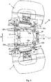
- FIG. 8 shows a top view of the connection arrangement 20 from FIG Fig. 1 after at least the bench 5 has been removed.
- connection arrangement 20 is designed for fastening the side luggage containers 7, 8 to the motorcycle 1 and for this purpose comprises a carrier element 22 and at least one rear vehicle frame section 21, which is defined, for example, by a rear frame of the motorcycle and is rigidly connected to a main frame (not shown). of the motorcycle 1 is connected.
- the vehicle frame section 21 comprises, for example, a left and a right side member, which extends essentially in the longitudinal direction L 'and are connected to one another with a connection section at the respective rear end thereof. It goes without saying that the vehicle frame section 21 can also have other components and / or a different geometry.
- the carrier element 22 is arranged on an upper side of the vehicle frame section 21 and extends transversely to a longitudinal direction L ′ of the vehicle frame section 21. This also means that, in an installed state, the carrier element 22 is positioned in the vehicle height direction between the upper side of the vehicle frame section 21 and the seat bench possibly arranged above it.
- the longitudinal direction L ′ of the vehicle frame section 21 is identical to the longitudinal direction L of the motorcycle 1.
- an arrangement can also be arranged below the vehicle frame section or within the vehicle frame section.
- the carrier element 22 is formed at a lateral left end 22a for connection to the left luggage container 7 and at a lateral right end 22b for connection to the right luggage container 8.
- connection between the carrier element 22 and the vehicle frame section 21 arranged underneath (in the vehicle height direction) is designed in such a way that the carrier element 22 is connected to the vehicle frame section 21 so that it can move relative to the latter.
- the support element 22 comprises a lateral support arm 23a, 23b as well as two transverse supports 24 connecting the lateral support arms 23a, 23b Luggage container 7,8 formed.
- two extensions instead of two extensions, only one or more than two extensions 26 can be provided per luggage container 7, 8.
- the carrier element 22 is designed as a frame element which has an almost rectangular or at least trapezoidal shape in that the lateral carrier arms 23a, 23b are connected to one another at their ends by one of the two cross members 24.
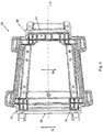
- FIG. 13 shows a plan view of a first embodiment of the connection arrangement 20, which is already shown in FIGS Fig. 1 and 2 has been described.
- the relative movement of the carrier element 22 with respect to the vehicle frame section 21 arranged below is defined by a translational movement B T of the carrier element 22 transversely to the longitudinal direction L 'of the vehicle frame section 21, i.e. in the transverse direction Q.
- the carrier element 22 is connected to the vehicle frame section 21 via a number of bearing points 30, four bearing points 30 are shown, translationally movable, the bearing points 30 each having a guide section 31 for guiding the translational movement B T.
- a range of motion of -20 mm y +20 mm, preferably -10 mm y +10 mm, particularly preferably -7 mm y +7 mm can be provided.
- the carrier element 22 connected to the vehicle frame section 21 is optionally shifted from the illustrated central neutral position by up to 20 mm, preferably up to 10 mm, particularly preferably up to 7 mm, in the direction of the left side or correspondingly in the direction of the right side can be. In this way there is an effective decoupling of movements provided, so that effective damping of pendulum movements of the vehicle 1 is made possible.
- a second embodiment of the connecting arrangement 20 is shown in a plan view, which also enables a relative movement of the carrier element 22 with respect to the vehicle frame section 21 arranged below it by a translational movement B T of the carrier element 22 transversely to the longitudinal direction L 'of the vehicle frame section 21, i.e. in the transverse direction Q, provides.
- the connecting arrangement 20 comprises two rail elements 40 aligned transversely to the longitudinal direction L 'of the vehicle frame section 21 Fig. 5 slide bearings 43 shown in more detail is connected to the rail elements 40 in a translationally displaceable manner.
- the carrier element 22 in the embodiment shown has extensions 41 which extend in the direction of the rail elements 40 and which comprise recesses 42 which partially encompass the rail elements 40 and in which the slide bearings 43 are arranged.
- the rail elements 40 can be designed, for example, as extruded profiles.
- FIG. 11 shows a plan view of a third embodiment of the connecting arrangement 20. This essentially corresponds to the other embodiments, so that the same reference symbols are used for identical or at least identically acting components and to the descriptions of FIG Figs. 1 to 5 is referred.
- the illustrated third embodiment differs in that the relative movement is defined by a rotational movement B D of the carrier element 22 about a defined axis of rotation D relative to the vehicle frame section 21.
- the axis of rotation D is aligned in the vertical direction of the vehicle frame section 21 or of the entire motorcycle 1 (that is, perpendicular to the image plane of the Fig. 6 ).
- the axis of rotation D is formed by a real axis of rotation D which is defined by a rotary bearing 51.
- the axis of rotation D viewed in the transverse direction, is arranged in a center, that is to say on the longitudinal direction L ′ of the vehicle frame section 21.
- the pivot bearing D is connected to a frame cross member 21a that connects the two longitudinal members of the vehicle frame section 21.
- a range of motion of the relative motion i.e. the rotary motion B D
- the carrier element 22 connected to the vehicle frame section 21 from a central neutral position that is, based on an alignment in the longitudinal direction L ') by a maximum of the angle ⁇ of up to + 10 ° or by up to -10 ° (preferably a maximum of + 5 ° and -5 °, particularly preferably a maximum of + 3 ° and -3 °) can be rotated within the defined plane of movement.
- the carrier element 22 is optionally connected to the vehicle frame section 21 in addition to the rotary bearing D via a number of bearing points 50, the bearing points 50 each having a guide section 51 for guiding the rotary movement B D have.
- Four bearing points 50 are shown, it also being possible for only two or more than four bearing points to be provided.
- the guide sections 51 are preferably each designed as an elongated hole or curved guide groove, which are arranged tangentially to a respective circular path K1, K2 or with their curvature along the respective circular path K1, K2.
- the centers of all circular paths K1, K2 are arranged coaxially to the axis of rotation D.
- FIG. 11 shows a plan view of a fourth embodiment of the connection arrangement 20. This essentially corresponds to the third embodiment according to FIG Fig. 6 match, so that the same reference numerals are used for the same or at least similarly acting components and to the descriptions of the Fig. 6 is referred.
- the fourth embodiment shown also provides a relative movement which is defined by a rotational movement B D of the carrier element 22 about a defined axis of rotation D v relative to the vehicle frame section 21.
- the real axis of rotation or a rotary bearing 51 defining the axis of rotation D is dispensed with.
- a virtual axis of rotation D v is provided.
- the carrier element 22 is connected to the vehicle frame section 21 in a relatively moveable manner solely via the number of bearing points 50, the bearing points 50 each having a guide section 51 for guiding the rotary movement.
- a range of motion of the rotary motion B D is selected according to the third embodiment.
- the defined axis of rotation D in the longitudinal direction L 'of the vehicle frame section 21 is in front of a geometric one Center of gravity S of the carrier element 22 is arranged.
- the defined axis of rotation D is arranged within the carrier element 22 and intersects the area defined and delimited by the carrier element 22.
- the defined real or the virtual axis of rotation D, D v can be arranged in the longitudinal direction L in front of the carrier element 22.
Landscapes
- Engineering & Computer Science (AREA)
- Mechanical Engineering (AREA)
- Automatic Cycles, And Cycles In General (AREA)
- Handcart (AREA)
Claims (13)
- Ensemble de liaison (20) servant à la fixation de contenants à bagages latéraux (7, 8) à une motocyclette ou à un véhicule similaire à une motocyclette, comportant :- une partie de cadre de véhicule arrière (21), et- un élément de support (22), lequel est réalisé de manière à s'étendre transversalement à une direction longitudinale (L') de la partie du cadre de véhicule (21) et est réalisé pour être relié à un contenant à bagages gauche (7) à une extrémité latérale gauche (22a) et pour être relié à un contenant à bagages droit (8) à une extrémité latérale droite (22b),l'élément de support (22) étant relié à la partie de cadre de véhicule (21) de manière mobile relativement par rapport à celle-ci etl'élément de support (22) comportant, dans la région de l'extrémité gauche (22a) et de l'extrémité droite (22b), respectivement un bras de support latéral (23a, 23b), caractérisé en ce que l'élément de support (22) comporte deux traverses (24) reliant l'un à l'autre les bras de supports latéraux (23a, 23b),les deux bras de supports latéraux (23a, 23b) étant réalisés respectivement pour être reliés au contenant à bagages latéral (7, 8) associé respectivement, l'élément de support (22) étant réalisé sous forme d'élément de cadre, les bras de supports latéraux (23a, 23b) étant reliés l'un à l'autre à leurs extrémités respectivement au moyen de l'une des deux traverses (24).
- Ensemble de liaison (20) selon la revendication 1, caractérisé en ce que le mouvement relatif est défini par un mouvement de translation (BT) transversalement à la direction longitudinale (L') de la partie de cadre de véhicule (21).
- Ensemble de liaison (20) selon la revendication 2, caractérisé en ce que l'élément de support (22) est relié à la partie de cadre de véhicule (21) de manière mobile en translation par le biais d'un certain nombre de points de palier (30), les points de palier (30) comprenant respectivement une partie de guidage (31) servant au guidage du mouvement de translation (BT).
- Ensemble de liaison (20) selon la revendication 2 ou 3, caractérisé en ce que l'ensemble de liaison (20) comporte au moins deux éléments rails (40) orientés transversalement à la direction longitudinale (L') de la partie de cadre de véhicule (21), l'élément de support (22) étant relié de manière déplaçable en translation aux éléments rails (40) au moyen de paliers lisses (43).
- Ensemble de liaison (20) selon la revendication 1, caractérisé en ce que le mouvement relatif est défini par un mouvement rotatif (BD) de l'élément de support (22) autour d'un axe de rotation défini (D) par rapport à la partie de cadre de véhicule (21).
- Ensemble de liaison (20) selon la revendication 5, caractérisé en ce que l'axe de rotation (D) est orienté sensiblement dans la direction de la hauteur de la partie de cadre de véhicule (21).
- Ensemble de liaison (20) selon la revendication 5 ou 6, caractérisé en ce que l'axe de rotation (D) est un axe de rotation réel qui est défini par un palier de rotation (51), ou est un axe de rotation virtuel (Dv).
- Ensemble de liaison (20) selon l'une des revendications 5 à 7, caractérisé en ce que l'élément de support (20) est relié à la partie de cadre de véhicule (21) de manière mobile relativement par le biais d'un certain nombre de points de palier (50), les points de palier (50) comprenant respectivement une partie de guidage (51) servant au guidage du mouvement de rotation (BD).
- Ensemble de liaison (20) selon l'une des revendications 5 à 8, caractérisé en ce que l'axe de rotation défini (D, Dv) est disposé devant un barycentre géométrique (S) de l'élément de support (22) dans la direction longitudinale (L') de la partie de cadre de véhicule (21).
- Ensemble de liaison (20) selon l'une des revendications 5 à 9, caractérisé en ce que l'axe de rotation défini (D, Dv) est disposé à l'intérieur de l'élément de support (22).
- Ensemble de liaison (20) selon l'une des revendications 1 à 10, caractérisé en ce que les bras de support latéraux (23a, 23b) comportent respectivement au moins une partie d'accrochage (25) pour l'accrochage libérable du contenant à bagages (7, 8) respectif.
- Motocyclette ou véhicule similaire à une motocyclette, comportant un ensemble de liaison (20) servant à la fixation de contenants à bagages latéraux (7, 8) à la motocyclette ou au véhicule (1) similaire à une motocyclette, caractérisé(e) en ce que l'ensemble de liaison (20) est réalisé selon l'une des revendications 1 à 11.
- Motocyclette ou véhicule (1) similaire à une motocyclette selon la revendication 12, caractérisé(e) en ce que la motocyclette ou le véhicule (1) similaire à une motocyclette comprend, sur un côté de véhicule, une saillie de fixation rigide reliée à un cadre de véhicule, laquelle est réalisée pour être reliée de manière amovible au contenant à bagages (7, 8) latéral respectif, de préférence pour être reliée dans une région inférieure du contenant à bagages (7, 8).
Applications Claiming Priority (2)
| Application Number | Priority Date | Filing Date | Title |
|---|---|---|---|
| DE102017212790.2A DE102017212790B4 (de) | 2017-07-26 | 2017-07-26 | Verbindungsanordnung für seitliche Gepäckbehältnisse eines Motorrades |
| PCT/EP2018/065917 WO2019020273A1 (fr) | 2017-07-26 | 2018-06-15 | Arrangement porteur pour compartiments à bagages latéraux d'une motocyclette |
Publications (2)
| Publication Number | Publication Date |
|---|---|
| EP3658447A1 EP3658447A1 (fr) | 2020-06-03 |
| EP3658447B1 true EP3658447B1 (fr) | 2021-12-29 |
Family
ID=62631113
Family Applications (1)
| Application Number | Title | Priority Date | Filing Date |
|---|---|---|---|
| EP18731826.6A Active EP3658447B1 (fr) | 2017-07-26 | 2018-06-15 | Support pour valises latérales d'une motocyclette |
Country Status (5)
| Country | Link |
|---|---|
| US (1) | US11794839B2 (fr) |
| EP (1) | EP3658447B1 (fr) |
| CN (1) | CN110809549B (fr) |
| DE (1) | DE102017212790B4 (fr) |
| WO (1) | WO2019020273A1 (fr) |
Families Citing this family (6)
| Publication number | Priority date | Publication date | Assignee | Title |
|---|---|---|---|---|
| DE102017221837B4 (de) | 2017-12-04 | 2021-11-18 | Bayerische Motoren Werke Aktiengesellschaft | Elastische Verbindungsanordnung für ein Motorrad |
| JP6866413B2 (ja) * | 2019-03-13 | 2021-04-28 | 本田技研工業株式会社 | 鞍乗り型車両 |
| DE102020122627A1 (de) * | 2020-08-31 | 2022-03-03 | Bayerische Motoren Werke Aktiengesellschaft | Neigefahrzeug mit Trägervorrichtung |
| JP7480426B2 (ja) * | 2021-03-30 | 2024-05-09 | 本田技研工業株式会社 | 車両、車両構造および車両用部品 |
| DE102021115159A1 (de) | 2021-06-11 | 2022-12-15 | Franz Weigl | Befestigungsvorrichtung zur Befestigung eines Oberkoffers an einem Motorrad und Adapter für eine Befestigungsvorrichtung |
| JP7735753B2 (ja) * | 2021-09-22 | 2025-09-09 | スズキ株式会社 | サイドケース取付構造 |
Citations (1)
| Publication number | Priority date | Publication date | Assignee | Title |
|---|---|---|---|---|
| DE29906623U1 (de) * | 1999-04-14 | 1999-09-23 | JF Motorsport GmbH, 61239 Ober-Mörlen | Kofferhalter |
Family Cites Families (34)
| Publication number | Priority date | Publication date | Assignee | Title |
|---|---|---|---|---|
| US4266702A (en) * | 1977-02-14 | 1981-05-12 | Jackson W S | Pannier mounting arrangement for cycles |
| US4174795A (en) * | 1977-02-14 | 1979-11-20 | Bohm Leslie E | Pannier mounting arrangement for cycles |
| JPS55101678U (fr) | 1979-01-10 | 1980-07-15 | ||
| US4562944A (en) * | 1979-02-01 | 1986-01-07 | Eclipse, Inc. | Adjustable connections on cycle rear carrier |
| US4353490A (en) * | 1979-10-24 | 1982-10-12 | Jackson W S | Pannier mounting system for cycles |
| US4325531A (en) * | 1980-02-11 | 1982-04-20 | Omholt Bruce D | Apparatus for removably securing a container to a carrier rack |
| DE3824610A1 (de) | 1988-07-20 | 1990-01-25 | Bayerische Motoren Werke Ag | Motorrad mit kofferanordnung |
| US5332134A (en) * | 1993-08-11 | 1994-07-26 | Chen Ming Yung | Bicycle luggage-carrier |
| CN2363945Y (zh) * | 1999-04-05 | 2000-02-16 | 捷安特(中国)有限公司 | 自行车货架联结构造 |
| US6299042B1 (en) * | 2000-04-10 | 2001-10-09 | Charles E. Smith | Touring bag support for motorcycles |
| CA2433184C (fr) * | 2002-07-16 | 2005-11-15 | Marcel Champagne | Porte-sac de bicyclette |
| JP3789906B2 (ja) | 2003-05-23 | 2006-06-28 | 株式会社ホンダアクセス | 自動二輪車のサドルバッグ取付装置 |
| AR042631A1 (es) * | 2003-12-19 | 2005-06-29 | Kuo Jen Lee | Porta equipaje y traba con cerradura antirrobo desmontable para vehiculos de dos ruedas |
| US20060138185A1 (en) * | 2004-12-27 | 2006-06-29 | Chien-Ping Lien | Single-piece instantly detachable locking device with a board for traveling bag on bicycle carrier |
| FR2896762A1 (fr) | 2006-01-27 | 2007-08-03 | Serge Roux | Porte-bagages amovible pour motocyclette |
| JP4770561B2 (ja) * | 2006-04-13 | 2011-09-14 | 株式会社豊田自動織機 | 車両用シート転回装置 |
| US20100282801A1 (en) * | 2009-05-05 | 2010-11-11 | John Willard | Collapsible Motorcycle Luggage Rack |
| DE102009003243A1 (de) * | 2009-05-19 | 2010-11-25 | Giant Mfg. Co., Ltd., Tachia | Gepäckträger für ein Fahrrad |
| US20110139843A1 (en) * | 2009-12-11 | 2011-06-16 | Thomas Barry H | Motorcycle seat-back adjustement device and method |
| US8360288B2 (en) * | 2010-12-14 | 2013-01-29 | General Cycle Co. | Detachable carrier support member for bicycle cargo racks |
| US8887974B2 (en) * | 2011-02-14 | 2014-11-18 | Kuryakyn Holdings, LLC | Adjustable accessory support assembly |
| NL2007674C2 (nl) * | 2011-10-31 | 2013-05-06 | 1T1 B V | Aangrijporgaan voor bevestiging van een houder aan een fietsbagagedrager. |
| JP5891062B2 (ja) * | 2011-11-22 | 2016-03-22 | 本田技研工業株式会社 | トランク |
| US8910842B2 (en) * | 2012-03-21 | 2014-12-16 | Cycling Sports Group, Inc. | Expansible bicycle cargo racks |
| US9010598B2 (en) | 2012-10-02 | 2015-04-21 | Triumph Designs Limited | Motorcycle stability system |
| JP5872447B2 (ja) | 2012-12-13 | 2016-03-01 | 本田技研工業株式会社 | 鞍乗り型車両の後部構造 |
| JP6071665B2 (ja) * | 2013-03-13 | 2017-02-01 | 本田技研工業株式会社 | 車両の後部構造 |
| DE102013223317B4 (de) * | 2013-11-15 | 2020-01-09 | Bayerische Motoren Werke Aktiengesellschaft | Gepäcksystem mit einer verstellbaren Befestigungsvorrichtung für einen Gepäckkoffer |
| US9440696B2 (en) * | 2014-02-12 | 2016-09-13 | Portage World-Wide, Inc. | Adjustabable bag harness for a bicycle |
| DE102014009766A1 (de) * | 2014-07-01 | 2016-01-07 | Invented Here B.V. | Gepäckträger-Anpassungskit zum Anpassen eines Gepäckträgergestells für ein Fahrrad |
| DE102014223048B4 (de) * | 2014-11-12 | 2022-08-04 | Bayerische Motoren Werke Aktiengesellschaft | Gepäcksystem gegen Pendeln |
| KR200479097Y1 (ko) * | 2015-09-04 | 2015-12-17 | 박종범 | 오토바이용 짐받이 |
| CA2975345A1 (fr) * | 2017-09-19 | 2019-03-19 | Tom S. Thomas | Support en d compact |
| DE202018105958U1 (de) * | 2018-10-17 | 2019-01-16 | Sheng-Kai LEE | Befestigungsplatte und Fahrradkorb mit dieser Befestigungsplatte |
-
2017
- 2017-07-26 DE DE102017212790.2A patent/DE102017212790B4/de active Active
-
2018
- 2018-06-15 WO PCT/EP2018/065917 patent/WO2019020273A1/fr not_active Ceased
- 2018-06-15 EP EP18731826.6A patent/EP3658447B1/fr active Active
- 2018-06-15 CN CN201880044368.4A patent/CN110809549B/zh active Active
-
2019
- 2019-12-18 US US16/718,788 patent/US11794839B2/en active Active
Patent Citations (1)
| Publication number | Priority date | Publication date | Assignee | Title |
|---|---|---|---|---|
| DE29906623U1 (de) * | 1999-04-14 | 1999-09-23 | JF Motorsport GmbH, 61239 Ober-Mörlen | Kofferhalter |
Also Published As
| Publication number | Publication date |
|---|---|
| US20200122800A1 (en) | 2020-04-23 |
| US11794839B2 (en) | 2023-10-24 |
| CN110809549B (zh) | 2021-10-26 |
| CN110809549A (zh) | 2020-02-18 |
| DE102017212790A1 (de) | 2019-01-31 |
| EP3658447A1 (fr) | 2020-06-03 |
| WO2019020273A1 (fr) | 2019-01-31 |
| DE102017212790B4 (de) | 2024-05-16 |
Similar Documents
| Publication | Publication Date | Title |
|---|---|---|
| EP3658447B1 (fr) | Support pour valises latérales d'une motocyclette | |
| EP2763891B1 (fr) | Élément de cadre et moteur pour bicyclette | |
| DE102014106928B4 (de) | Gleisloser Routenzug | |
| EP2406122B1 (fr) | Élément de cadre pour le guidage d'un câble pour cadre de suspension de bicyclette | |
| DE202016008844U1 (de) | "AFW"-Fahrzeugaufhängung (Varianten) | |
| DE102020208140A1 (de) | Kippstruktur für Mobilitätsvorrichtung und Mobilitätsvorrichtung mit dieser | |
| DE102009026297B4 (de) | Cockpitquerträger mit variablem Lenksäulenneigungswinkel | |
| EP3529136A1 (fr) | Dispositif de raccordement pivotant pour coffre arrière | |
| WO2018072918A1 (fr) | Scooter comprenant un ensemble repose-pied | |
| DE202004006563U1 (de) | Fahrrad mit einem zusammenschiebbaren Rahmenrohrsatz | |
| DE102017221837B4 (de) | Elastische Verbindungsanordnung für ein Motorrad | |
| DE102020130391B4 (de) | Luftleitvorrichtung für eine Karosseriefront einer Kraftfahrzeugkarosserie und Kraftfahrzeugkarosserie | |
| DE102004029388B4 (de) | Liegedreirad-Vorrichtung mit gedämpftem Lenksystem | |
| EP3383732A1 (fr) | Ensemble guidon à intégration de fonctions pour une motocyclette | |
| EP3380393A1 (fr) | Cycle à plusieurs voies | |
| DE20112448U1 (de) | Fahrradrahmen | |
| DE10253060A1 (de) | Doppelachse | |
| DE102013100090B4 (de) | Mehrspuriges Kinderfahrzeug | |
| WO2005051754A1 (fr) | Fourche telescopique pour roue avant orientable de vehicule | |
| AT502739B1 (de) | Mehrspuriges fahrzeug | |
| DE102012204031B4 (de) | Radaufhängung für ein lenkbares Rad | |
| DE602004001416T2 (de) | Lenkeinrichtung mit erhöhter Vibrationseigenfrequenz und entprechendes Fahrzeug | |
| WO2020182565A1 (fr) | Bicyclette de transport | |
| DE29716495U1 (de) | Fahrradrahmen | |
| DE202005002840U1 (de) | Vorderradaufhängung eines Quades mit zwei Schwenkarmen |
Legal Events
| Date | Code | Title | Description |
|---|---|---|---|
| STAA | Information on the status of an ep patent application or granted ep patent |
Free format text: STATUS: UNKNOWN |
|
| STAA | Information on the status of an ep patent application or granted ep patent |
Free format text: STATUS: THE INTERNATIONAL PUBLICATION HAS BEEN MADE |
|
| PUAI | Public reference made under article 153(3) epc to a published international application that has entered the european phase |
Free format text: ORIGINAL CODE: 0009012 |
|
| STAA | Information on the status of an ep patent application or granted ep patent |
Free format text: STATUS: REQUEST FOR EXAMINATION WAS MADE |
|
| 17P | Request for examination filed |
Effective date: 20200127 |
|
| AK | Designated contracting states |
Kind code of ref document: A1 Designated state(s): AL AT BE BG CH CY CZ DE DK EE ES FI FR GB GR HR HU IE IS IT LI LT LU LV MC MK MT NL NO PL PT RO RS SE SI SK SM TR |
|
| AX | Request for extension of the european patent |
Extension state: BA ME |
|
| DAV | Request for validation of the european patent (deleted) | ||
| DAX | Request for extension of the european patent (deleted) | ||
| REG | Reference to a national code |
Ref country code: DE Ref legal event code: R079 Ref document number: 502018008345 Country of ref document: DE Free format text: PREVIOUS MAIN CLASS: B62J0009000000 Ipc: B62J0009240000 |
|
| GRAP | Despatch of communication of intention to grant a patent |
Free format text: ORIGINAL CODE: EPIDOSNIGR1 |
|
| STAA | Information on the status of an ep patent application or granted ep patent |
Free format text: STATUS: GRANT OF PATENT IS INTENDED |
|
| RIC1 | Information provided on ipc code assigned before grant |
Ipc: B62J 9/23 20200101ALI20210818BHEP Ipc: B62J 9/24 20200101AFI20210818BHEP |
|
| INTG | Intention to grant announced |
Effective date: 20210921 |
|
| RIN1 | Information on inventor provided before grant (corrected) |
Inventor name: MUEHLMANN, MATHIAS Inventor name: GOLLING, ADRIAN |
|
| GRAS | Grant fee paid |
Free format text: ORIGINAL CODE: EPIDOSNIGR3 |
|
| GRAA | (expected) grant |
Free format text: ORIGINAL CODE: 0009210 |
|
| STAA | Information on the status of an ep patent application or granted ep patent |
Free format text: STATUS: THE PATENT HAS BEEN GRANTED |
|
| AK | Designated contracting states |
Kind code of ref document: B1 Designated state(s): AL AT BE BG CH CY CZ DE DK EE ES FI FR GB GR HR HU IE IS IT LI LT LU LV MC MK MT NL NO PL PT RO RS SE SI SK SM TR |
|
| REG | Reference to a national code |
Ref country code: GB Ref legal event code: FG4D Free format text: NOT ENGLISH |
|
| REG | Reference to a national code |
Ref country code: CH Ref legal event code: EP |
|
| REG | Reference to a national code |
Ref country code: AT Ref legal event code: REF Ref document number: 1458493 Country of ref document: AT Kind code of ref document: T Effective date: 20220115 |
|
| REG | Reference to a national code |
Ref country code: IE Ref legal event code: FG4D Free format text: LANGUAGE OF EP DOCUMENT: GERMAN |
|
| REG | Reference to a national code |
Ref country code: DE Ref legal event code: R096 Ref document number: 502018008345 Country of ref document: DE |
|
| REG | Reference to a national code |
Ref country code: LT Ref legal event code: MG9D |
|
| PG25 | Lapsed in a contracting state [announced via postgrant information from national office to epo] |
Ref country code: RS Free format text: LAPSE BECAUSE OF FAILURE TO SUBMIT A TRANSLATION OF THE DESCRIPTION OR TO PAY THE FEE WITHIN THE PRESCRIBED TIME-LIMIT Effective date: 20211229 Ref country code: LT Free format text: LAPSE BECAUSE OF FAILURE TO SUBMIT A TRANSLATION OF THE DESCRIPTION OR TO PAY THE FEE WITHIN THE PRESCRIBED TIME-LIMIT Effective date: 20211229 Ref country code: FI Free format text: LAPSE BECAUSE OF FAILURE TO SUBMIT A TRANSLATION OF THE DESCRIPTION OR TO PAY THE FEE WITHIN THE PRESCRIBED TIME-LIMIT Effective date: 20211229 Ref country code: BG Free format text: LAPSE BECAUSE OF FAILURE TO SUBMIT A TRANSLATION OF THE DESCRIPTION OR TO PAY THE FEE WITHIN THE PRESCRIBED TIME-LIMIT Effective date: 20220329 |
|
| REG | Reference to a national code |
Ref country code: NL Ref legal event code: MP Effective date: 20211229 |
|
| PG25 | Lapsed in a contracting state [announced via postgrant information from national office to epo] |
Ref country code: SE Free format text: LAPSE BECAUSE OF FAILURE TO SUBMIT A TRANSLATION OF THE DESCRIPTION OR TO PAY THE FEE WITHIN THE PRESCRIBED TIME-LIMIT Effective date: 20211229 Ref country code: NO Free format text: LAPSE BECAUSE OF FAILURE TO SUBMIT A TRANSLATION OF THE DESCRIPTION OR TO PAY THE FEE WITHIN THE PRESCRIBED TIME-LIMIT Effective date: 20220329 Ref country code: LV Free format text: LAPSE BECAUSE OF FAILURE TO SUBMIT A TRANSLATION OF THE DESCRIPTION OR TO PAY THE FEE WITHIN THE PRESCRIBED TIME-LIMIT Effective date: 20211229 Ref country code: HR Free format text: LAPSE BECAUSE OF FAILURE TO SUBMIT A TRANSLATION OF THE DESCRIPTION OR TO PAY THE FEE WITHIN THE PRESCRIBED TIME-LIMIT Effective date: 20211229 Ref country code: GR Free format text: LAPSE BECAUSE OF FAILURE TO SUBMIT A TRANSLATION OF THE DESCRIPTION OR TO PAY THE FEE WITHIN THE PRESCRIBED TIME-LIMIT Effective date: 20220330 |
|
| PG25 | Lapsed in a contracting state [announced via postgrant information from national office to epo] |
Ref country code: NL Free format text: LAPSE BECAUSE OF FAILURE TO SUBMIT A TRANSLATION OF THE DESCRIPTION OR TO PAY THE FEE WITHIN THE PRESCRIBED TIME-LIMIT Effective date: 20211229 |
|
| PG25 | Lapsed in a contracting state [announced via postgrant information from national office to epo] |
Ref country code: SM Free format text: LAPSE BECAUSE OF FAILURE TO SUBMIT A TRANSLATION OF THE DESCRIPTION OR TO PAY THE FEE WITHIN THE PRESCRIBED TIME-LIMIT Effective date: 20211229 Ref country code: SK Free format text: LAPSE BECAUSE OF FAILURE TO SUBMIT A TRANSLATION OF THE DESCRIPTION OR TO PAY THE FEE WITHIN THE PRESCRIBED TIME-LIMIT Effective date: 20211229 Ref country code: RO Free format text: LAPSE BECAUSE OF FAILURE TO SUBMIT A TRANSLATION OF THE DESCRIPTION OR TO PAY THE FEE WITHIN THE PRESCRIBED TIME-LIMIT Effective date: 20211229 Ref country code: PT Free format text: LAPSE BECAUSE OF FAILURE TO SUBMIT A TRANSLATION OF THE DESCRIPTION OR TO PAY THE FEE WITHIN THE PRESCRIBED TIME-LIMIT Effective date: 20220429 Ref country code: ES Free format text: LAPSE BECAUSE OF FAILURE TO SUBMIT A TRANSLATION OF THE DESCRIPTION OR TO PAY THE FEE WITHIN THE PRESCRIBED TIME-LIMIT Effective date: 20211229 Ref country code: EE Free format text: LAPSE BECAUSE OF FAILURE TO SUBMIT A TRANSLATION OF THE DESCRIPTION OR TO PAY THE FEE WITHIN THE PRESCRIBED TIME-LIMIT Effective date: 20211229 Ref country code: CZ Free format text: LAPSE BECAUSE OF FAILURE TO SUBMIT A TRANSLATION OF THE DESCRIPTION OR TO PAY THE FEE WITHIN THE PRESCRIBED TIME-LIMIT Effective date: 20211229 |
|
| PG25 | Lapsed in a contracting state [announced via postgrant information from national office to epo] |
Ref country code: PL Free format text: LAPSE BECAUSE OF FAILURE TO SUBMIT A TRANSLATION OF THE DESCRIPTION OR TO PAY THE FEE WITHIN THE PRESCRIBED TIME-LIMIT Effective date: 20211229 |
|
| PG25 | Lapsed in a contracting state [announced via postgrant information from national office to epo] |
Ref country code: IS Free format text: LAPSE BECAUSE OF FAILURE TO SUBMIT A TRANSLATION OF THE DESCRIPTION OR TO PAY THE FEE WITHIN THE PRESCRIBED TIME-LIMIT Effective date: 20220429 |
|
| REG | Reference to a national code |
Ref country code: DE Ref legal event code: R097 Ref document number: 502018008345 Country of ref document: DE |
|
| PG25 | Lapsed in a contracting state [announced via postgrant information from national office to epo] |
Ref country code: DK Free format text: LAPSE BECAUSE OF FAILURE TO SUBMIT A TRANSLATION OF THE DESCRIPTION OR TO PAY THE FEE WITHIN THE PRESCRIBED TIME-LIMIT Effective date: 20211229 Ref country code: AL Free format text: LAPSE BECAUSE OF FAILURE TO SUBMIT A TRANSLATION OF THE DESCRIPTION OR TO PAY THE FEE WITHIN THE PRESCRIBED TIME-LIMIT Effective date: 20211229 |
|
| PLBE | No opposition filed within time limit |
Free format text: ORIGINAL CODE: 0009261 |
|
| STAA | Information on the status of an ep patent application or granted ep patent |
Free format text: STATUS: NO OPPOSITION FILED WITHIN TIME LIMIT |
|
| 26N | No opposition filed |
Effective date: 20220930 |
|
| PG25 | Lapsed in a contracting state [announced via postgrant information from national office to epo] |
Ref country code: MC Free format text: LAPSE BECAUSE OF FAILURE TO SUBMIT A TRANSLATION OF THE DESCRIPTION OR TO PAY THE FEE WITHIN THE PRESCRIBED TIME-LIMIT Effective date: 20211229 |
|
| REG | Reference to a national code |
Ref country code: CH Ref legal event code: PL |
|
| REG | Reference to a national code |
Ref country code: BE Ref legal event code: MM Effective date: 20220630 |
|
| PG25 | Lapsed in a contracting state [announced via postgrant information from national office to epo] |
Ref country code: SI Free format text: LAPSE BECAUSE OF FAILURE TO SUBMIT A TRANSLATION OF THE DESCRIPTION OR TO PAY THE FEE WITHIN THE PRESCRIBED TIME-LIMIT Effective date: 20211229 |
|
| PG25 | Lapsed in a contracting state [announced via postgrant information from national office to epo] |
Ref country code: LU Free format text: LAPSE BECAUSE OF NON-PAYMENT OF DUE FEES Effective date: 20220615 Ref country code: LI Free format text: LAPSE BECAUSE OF NON-PAYMENT OF DUE FEES Effective date: 20220630 Ref country code: IE Free format text: LAPSE BECAUSE OF NON-PAYMENT OF DUE FEES Effective date: 20220615 Ref country code: CH Free format text: LAPSE BECAUSE OF NON-PAYMENT OF DUE FEES Effective date: 20220630 |
|
| PG25 | Lapsed in a contracting state [announced via postgrant information from national office to epo] |
Ref country code: BE Free format text: LAPSE BECAUSE OF NON-PAYMENT OF DUE FEES Effective date: 20220630 |
|
| P01 | Opt-out of the competence of the unified patent court (upc) registered |
Effective date: 20230502 |
|
| PG25 | Lapsed in a contracting state [announced via postgrant information from national office to epo] |
Ref country code: MK Free format text: LAPSE BECAUSE OF FAILURE TO SUBMIT A TRANSLATION OF THE DESCRIPTION OR TO PAY THE FEE WITHIN THE PRESCRIBED TIME-LIMIT Effective date: 20211229 Ref country code: CY Free format text: LAPSE BECAUSE OF FAILURE TO SUBMIT A TRANSLATION OF THE DESCRIPTION OR TO PAY THE FEE WITHIN THE PRESCRIBED TIME-LIMIT Effective date: 20211229 |
|
| PG25 | Lapsed in a contracting state [announced via postgrant information from national office to epo] |
Ref country code: HU Free format text: LAPSE BECAUSE OF FAILURE TO SUBMIT A TRANSLATION OF THE DESCRIPTION OR TO PAY THE FEE WITHIN THE PRESCRIBED TIME-LIMIT; INVALID AB INITIO Effective date: 20180615 |
|
| PG25 | Lapsed in a contracting state [announced via postgrant information from national office to epo] |
Ref country code: TR Free format text: LAPSE BECAUSE OF FAILURE TO SUBMIT A TRANSLATION OF THE DESCRIPTION OR TO PAY THE FEE WITHIN THE PRESCRIBED TIME-LIMIT Effective date: 20211229 |
|
| REG | Reference to a national code |
Ref country code: AT Ref legal event code: MM01 Ref document number: 1458493 Country of ref document: AT Kind code of ref document: T Effective date: 20230615 |
|
| PG25 | Lapsed in a contracting state [announced via postgrant information from national office to epo] |
Ref country code: MT Free format text: LAPSE BECAUSE OF FAILURE TO SUBMIT A TRANSLATION OF THE DESCRIPTION OR TO PAY THE FEE WITHIN THE PRESCRIBED TIME-LIMIT Effective date: 20211229 |
|
| PG25 | Lapsed in a contracting state [announced via postgrant information from national office to epo] |
Ref country code: AT Free format text: LAPSE BECAUSE OF NON-PAYMENT OF DUE FEES Effective date: 20230615 |
|
| PG25 | Lapsed in a contracting state [announced via postgrant information from national office to epo] |
Ref country code: AT Free format text: LAPSE BECAUSE OF NON-PAYMENT OF DUE FEES Effective date: 20230615 |
|
| PGFP | Annual fee paid to national office [announced via postgrant information from national office to epo] |
Ref country code: DE Payment date: 20250605 Year of fee payment: 8 |
|
| PGFP | Annual fee paid to national office [announced via postgrant information from national office to epo] |
Ref country code: GB Payment date: 20250620 Year of fee payment: 8 |
|
| PGFP | Annual fee paid to national office [announced via postgrant information from national office to epo] |
Ref country code: FR Payment date: 20250626 Year of fee payment: 8 |
|
| PGFP | Annual fee paid to national office [announced via postgrant information from national office to epo] |
Ref country code: IT Payment date: 20250630 Year of fee payment: 8 |
|
| PGFP | Annual fee paid to national office [announced via postgrant information from national office to epo] |
Ref country code: AT Payment date: 20260410 Year of fee payment: 5 |