EP3658698B1 - Procédé de fabrication d'une couche monophasée en composé intermétallique - Google Patents
Procédé de fabrication d'une couche monophasée en composé intermétallique Download PDFInfo
- Publication number
- EP3658698B1 EP3658698B1 EP18750326.3A EP18750326A EP3658698B1 EP 3658698 B1 EP3658698 B1 EP 3658698B1 EP 18750326 A EP18750326 A EP 18750326A EP 3658698 B1 EP3658698 B1 EP 3658698B1
- Authority
- EP
- European Patent Office
- Prior art keywords
- substrate
- intermetallic
- phase
- layer
- intermetallic compound
- Prior art date
- Legal status (The legal status is an assumption and is not a legal conclusion. Google has not performed a legal analysis and makes no representation as to the accuracy of the status listed.)
- Active
Links
Images
Classifications
-
- C—CHEMISTRY; METALLURGY
- C23—COATING METALLIC MATERIAL; COATING MATERIAL WITH METALLIC MATERIAL; CHEMICAL SURFACE TREATMENT; DIFFUSION TREATMENT OF METALLIC MATERIAL; COATING BY VACUUM EVAPORATION, BY SPUTTERING, BY ION IMPLANTATION OR BY CHEMICAL VAPOUR DEPOSITION, IN GENERAL; INHIBITING CORROSION OF METALLIC MATERIAL OR INCRUSTATION IN GENERAL
- C23C—COATING METALLIC MATERIAL; COATING MATERIAL WITH METALLIC MATERIAL; SURFACE TREATMENT OF METALLIC MATERIAL BY DIFFUSION INTO THE SURFACE, BY CHEMICAL CONVERSION OR SUBSTITUTION; COATING BY VACUUM EVAPORATION, BY SPUTTERING, BY ION IMPLANTATION OR BY CHEMICAL VAPOUR DEPOSITION, IN GENERAL
- C23C14/00—Coating by vacuum evaporation, by sputtering or by ion implantation of the coating forming material
- C23C14/22—Coating by vacuum evaporation, by sputtering or by ion implantation of the coating forming material characterised by the process of coating
- C23C14/34—Sputtering
- C23C14/35—Sputtering by application of a magnetic field, e.g. magnetron sputtering
-
- C—CHEMISTRY; METALLURGY
- C23—COATING METALLIC MATERIAL; COATING MATERIAL WITH METALLIC MATERIAL; CHEMICAL SURFACE TREATMENT; DIFFUSION TREATMENT OF METALLIC MATERIAL; COATING BY VACUUM EVAPORATION, BY SPUTTERING, BY ION IMPLANTATION OR BY CHEMICAL VAPOUR DEPOSITION, IN GENERAL; INHIBITING CORROSION OF METALLIC MATERIAL OR INCRUSTATION IN GENERAL
- C23C—COATING METALLIC MATERIAL; COATING MATERIAL WITH METALLIC MATERIAL; SURFACE TREATMENT OF METALLIC MATERIAL BY DIFFUSION INTO THE SURFACE, BY CHEMICAL CONVERSION OR SUBSTITUTION; COATING BY VACUUM EVAPORATION, BY SPUTTERING, BY ION IMPLANTATION OR BY CHEMICAL VAPOUR DEPOSITION, IN GENERAL
- C23C14/00—Coating by vacuum evaporation, by sputtering or by ion implantation of the coating forming material
- C23C14/06—Coating by vacuum evaporation, by sputtering or by ion implantation of the coating forming material characterised by the coating material
- C23C14/14—Metallic material, boron or silicon
- C23C14/16—Metallic material, boron or silicon on metallic substrates or on substrates of boron or silicon
-
- C—CHEMISTRY; METALLURGY
- C23—COATING METALLIC MATERIAL; COATING MATERIAL WITH METALLIC MATERIAL; CHEMICAL SURFACE TREATMENT; DIFFUSION TREATMENT OF METALLIC MATERIAL; COATING BY VACUUM EVAPORATION, BY SPUTTERING, BY ION IMPLANTATION OR BY CHEMICAL VAPOUR DEPOSITION, IN GENERAL; INHIBITING CORROSION OF METALLIC MATERIAL OR INCRUSTATION IN GENERAL
- C23C—COATING METALLIC MATERIAL; COATING MATERIAL WITH METALLIC MATERIAL; SURFACE TREATMENT OF METALLIC MATERIAL BY DIFFUSION INTO THE SURFACE, BY CHEMICAL CONVERSION OR SUBSTITUTION; COATING BY VACUUM EVAPORATION, BY SPUTTERING, BY ION IMPLANTATION OR BY CHEMICAL VAPOUR DEPOSITION, IN GENERAL
- C23C14/00—Coating by vacuum evaporation, by sputtering or by ion implantation of the coating forming material
- C23C14/22—Coating by vacuum evaporation, by sputtering or by ion implantation of the coating forming material characterised by the process of coating
- C23C14/34—Sputtering
- C23C14/3407—Cathode assembly for sputtering apparatus, e.g. Target
- C23C14/3414—Metallurgical or chemical aspects of target preparation, e.g. casting, powder metallurgy
-
- H—ELECTRICITY
- H01—ELECTRIC ELEMENTS
- H01J—ELECTRIC DISCHARGE TUBES OR DISCHARGE LAMPS
- H01J37/00—Discharge tubes with provision for introducing objects or material to be exposed to the discharge, e.g. for the purpose of examination or processing thereof
- H01J37/32—Gas-filled discharge tubes
- H01J37/34—Gas-filled discharge tubes operating with cathodic sputtering
- H01J37/3411—Constructional aspects of the reactor
- H01J37/3414—Targets
- H01J37/3426—Material
-
- B—PERFORMING OPERATIONS; TRANSPORTING
- B22—CASTING; POWDER METALLURGY
- B22F—WORKING METALLIC POWDER; MANUFACTURE OF ARTICLES FROM METALLIC POWDER; MAKING METALLIC POWDER; APPARATUS OR DEVICES SPECIALLY ADAPTED FOR METALLIC POWDER
- B22F3/00—Manufacture of workpieces or articles from metallic powder characterised by the manner of compacting or sintering; Apparatus specially adapted therefor ; Presses and furnaces
- B22F3/10—Sintering only
- B22F3/105—Sintering only by using electric current other than for infrared radiant energy, laser radiation or plasma ; by ultrasonic bonding
- B22F2003/1051—Sintering only by using electric current other than for infrared radiant energy, laser radiation or plasma ; by ultrasonic bonding by electric discharge
-
- B—PERFORMING OPERATIONS; TRANSPORTING
- B22—CASTING; POWDER METALLURGY
- B22F—WORKING METALLIC POWDER; MANUFACTURE OF ARTICLES FROM METALLIC POWDER; MAKING METALLIC POWDER; APPARATUS OR DEVICES SPECIALLY ADAPTED FOR METALLIC POWDER
- B22F3/00—Manufacture of workpieces or articles from metallic powder characterised by the manner of compacting or sintering; Apparatus specially adapted therefor ; Presses and furnaces
- B22F3/24—After-treatment of workpieces or articles
- B22F2003/247—Removing material: carving, cleaning, grinding, hobbing, honing, lapping, polishing, milling, shaving, skiving, turning the surface
-
- B—PERFORMING OPERATIONS; TRANSPORTING
- B22—CASTING; POWDER METALLURGY
- B22F—WORKING METALLIC POWDER; MANUFACTURE OF ARTICLES FROM METALLIC POWDER; MAKING METALLIC POWDER; APPARATUS OR DEVICES SPECIALLY ADAPTED FOR METALLIC POWDER
- B22F2202/00—Treatment under specific physical conditions
- B22F2202/13—Use of plasma
-
- B—PERFORMING OPERATIONS; TRANSPORTING
- B22—CASTING; POWDER METALLURGY
- B22F—WORKING METALLIC POWDER; MANUFACTURE OF ARTICLES FROM METALLIC POWDER; MAKING METALLIC POWDER; APPARATUS OR DEVICES SPECIALLY ADAPTED FOR METALLIC POWDER
- B22F2998/00—Supplementary information concerning processes or compositions relating to powder metallurgy
- B22F2998/10—Processes characterised by the sequence of their steps
-
- B—PERFORMING OPERATIONS; TRANSPORTING
- B22—CASTING; POWDER METALLURGY
- B22F—WORKING METALLIC POWDER; MANUFACTURE OF ARTICLES FROM METALLIC POWDER; MAKING METALLIC POWDER; APPARATUS OR DEVICES SPECIALLY ADAPTED FOR METALLIC POWDER
- B22F2999/00—Aspects linked to processes or compositions used in powder metallurgy
-
- B—PERFORMING OPERATIONS; TRANSPORTING
- B22—CASTING; POWDER METALLURGY
- B22F—WORKING METALLIC POWDER; MANUFACTURE OF ARTICLES FROM METALLIC POWDER; MAKING METALLIC POWDER; APPARATUS OR DEVICES SPECIALLY ADAPTED FOR METALLIC POWDER
- B22F7/00—Manufacture of composite layers, workpieces, or articles, comprising metallic powder, by sintering the powder, with or without compacting wherein at least one part is obtained by sintering or compression
- B22F7/06—Manufacture of composite layers, workpieces, or articles, comprising metallic powder, by sintering the powder, with or without compacting wherein at least one part is obtained by sintering or compression of composite workpieces or articles from parts, e.g. to form tipped tools
-
- B—PERFORMING OPERATIONS; TRANSPORTING
- B22—CASTING; POWDER METALLURGY
- B22F—WORKING METALLIC POWDER; MANUFACTURE OF ARTICLES FROM METALLIC POWDER; MAKING METALLIC POWDER; APPARATUS OR DEVICES SPECIALLY ADAPTED FOR METALLIC POWDER
- B22F7/00—Manufacture of composite layers, workpieces, or articles, comprising metallic powder, by sintering the powder, with or without compacting wherein at least one part is obtained by sintering or compression
- B22F7/06—Manufacture of composite layers, workpieces, or articles, comprising metallic powder, by sintering the powder, with or without compacting wherein at least one part is obtained by sintering or compression of composite workpieces or articles from parts, e.g. to form tipped tools
- B22F7/062—Manufacture of composite layers, workpieces, or articles, comprising metallic powder, by sintering the powder, with or without compacting wherein at least one part is obtained by sintering or compression of composite workpieces or articles from parts, e.g. to form tipped tools involving the connection or repairing of preformed parts
Definitions
- the invention relates to a method for producing a single-phase intermetallic layer of an intermetallic compound of a single-phase catalyst material of the type Ga x Pd y or Al 13 Fe 4 on a substrate according to the first patent claim.
- Ga x Pd y is preferably formed by GaPd 2.
- Single-phase intermetallic compounds, in particular catalytically active particles and coatings made of intermetallic compounds of the type GaPd 2 and Al 13 Fe 4 are basically known as catalyst materials.
- a typical application area for catalytically active coatings in general is structured reactors, in which the catalytically active coating is arranged on a structured substrate with a high surface area per volume in the reactor in order to achieve good accessibility of the catalytically active surface.
- structured substrates include metallic nets, metallic or ceramic fiber braids and films with incorporated channel structures, which typically have dimensions in the range of a few micrometers to a few millimeters transverse to the main flow direction.
- the latter films can be used to build so-called microstructure reactors, e.g.
- reaction and cooling/heating films which, in addition to the minimized mass transport resistance between fluid and catalyst, also have a very high heat transfer performance from the reacting fluid to a heat transfer fluid or vice versa. This in turn is a prerequisite for good temperature control, which has a positive effect on the yield and service life of the catalysts, and also for efficient utilization of the heat released during the reaction, for example to generate process steam or efficient supply of the heat required for the reaction.
- Exothermic hydrogenations such as the semi-hydrogenation of acetylene, which is advantageously carried out on intermetallic compounds of the type GaPd 2 or Al 13 Fe 4 , represent an important class of reactions that can be advantageously carried out in structured reactors.
- EP 1 339 485 B1 a microstructure reactor for carrying out a chemical reaction between two reaction partners, which can be introduced separately into the microstructure reactor as reactants and can be removed from it as a product after the reaction has taken place.
- the reactor itself consists of an alternating layered structure of flat flow channel modules, i.e. made of structured films, using microstructure technology, with a first flow channel module with flow channels that have an inlet and an outlet for a first reactant, and a second flow channel module with flow channels into which a second reactant can be introduced from the outside.
- the EN 10 2005 022 958 B3 discloses a microstructure reactor, in this case for carrying out a chemical two-phase hydrogenation between two reactants.
- the device has a layered structure with structured films and comprises a first passage fraction with channels for a fluid fraction, which via a plurality of openings into at least one reaction volume filled with a bed of particles of a catalyst.
- a layered construction of a microstructure reactor is also shown EN 10 2012 100 344 A1
- the actual reaction module is designed as a separate module and carrier for a catalyst as an insert in the microreactor.
- a fundamental problem when using catalytically active coatings in structured reactors is their production, especially when it comes to special materials such as intermetallic compounds of the type GaPd 2 or Al 13 Fe 4 , the synthesis of which is particularly complex due to its high specific surface area.
- the intermetallic compound GaPd 2 can be synthesized in nanoparticulate form.
- the nanoparticles obtained in this way can be converted into a printable suspension and printed as wall coatings in preformed microstructures, for example, using an inkjet or screen printing process.
- the nanoparticles are distributed very finely and precisely on the surface of the microstructure.
- porous wall coatings of adjustable thickness in the range of 1 - 10 ⁇ m can be produced by drop-on-demand inkjet printing.
- the aforementioned intermetallic catalyst materials of the type GaPd 2 or Al 13 Fe 4 require the presence of a single-phase modification with a specific crystal structure in order to function reliably.
- the formation of the intermetallic compound is essential because the formation of the characteristic crystal lattice isolates the catalytically active centers and changes the electronic structure compared to the elemental or alloy compounds ( M. Armbrüster, K. Kovnir, M. Behrens, D. Teschner, Y. Grin, R. Schlögl, J. Am. Chem. Soc. 2010, 132, 14745-14747 and M. Armbrüster, K. Kovnir, M. Friedrich, D. Teschner, G. Wowsnick, M. Hahne, P.
- one object of the invention is to propose a method for producing a single-phase intermetallic layer of intermetallic compounds, in particular of the type Ga x Pd y and Al 13 Fe 4 on a substrate, which is particularly suitable for a simple and cost-effective as well as large-area coating of structured substrates such as microstructured films, metallic nets, metallic or ceramic fibers and fiber braids and 3D-printed structures.
- the solution to the problem is based on a method for producing a single-phase layer of intermetallic compounds of the type Ga x Pd y , preferably GaPd 2 , or Al 13 Fe 4 on a substrate using a DC magnetron sputtering method.
- the particular difficulty lies in designing the sputtering process in such a way that the composition of the intermetallic phase is ensured over the entire layer.
- each of the sputtering targets used in the sputtering process is formed completely, at least at the depth used during the sputtering process, and also homogeneously in the atomic range, in a single phase from only one of the intermetallic compounds of the type GaPd 2 or Al 13 Fe 4 .
- a sputtering target is a cathode with a solid body with a cathode surface made of the aforementioned single-phase intermetallic compound.
- the sputtering target is applied as a layer made of the single-phase intermetallic compound to a metallic base body as a carrier element.
- a metallic base body as a carrier element.
- one or more ternary phases can form. However, these are not involved in the sputtering process and are therefore harmless in this respect.
- the intermetallic compound of an element combination of the type Ga x Pd y , preferably GaPd 2 , or Al 13 Fe 4 , is present in the layer as a single phase and is not divided into two or more different phases in the layer.
- sputtering targets in the above sense each consisting of an intermetallic compound, according to the invention the intermetallic compound to be deposited.
- An intermetallic compound of the type GaPd 2 or Al 13 Fe 4 is defined in the context of this patent application as an intermetallic compound which is composed of, preferably only, the compounds GaPd 2 or Al 13 Fe 4. It preferably does not comprise any additional doping elements.
- a single-phase layer of intermetallic compounds of the type GaPd 2 or Al 13 Fe 4 is defined as a layer in which the intermetallic compound is present in a single phase.
- the single-phase layer can also contain other possible phases, e.g. from impurities, which do not, however, consist of the element combinations of the intermetallic compound.
- the single-phase layer of intermetallic compounds consists only of the intermetallic compound of the type GaPd 2 or Al 13 Fe 4 and preferably contains no additional doping elements.
- the single-phase nature of the layer can be verified using X-ray structure analysis (XRD) without necessarily having to elucidate the material down to the atomic level.
- XRD X-ray structure analysis
- the phase composition is shown in the diffractograms, with the single-phase nature being demonstrable by the exclusive appearance of the characteristic reflections in the diffractogram.
- a preferred method therefore includes the manufacture of the cathodes in the process.
- single-phase intermetallic compounds as starting material enables the production of targets made of intermetallic compounds, for example GaPd 2 or Al 13 Fe 4 targets.
- the cathodes are produced by means of a surface diffusion-related transport rearrangement, such as a sintering process from a powder of the intermetallic compound, of the type Ga x Pd y or Al 13 Fe 4 , where Ga x Pd y is further preferably formed by GaPd 2 .
- the intermetallic powder for the aforementioned sintering process is synthesized in a single phase, more preferably obtained by means of a solid-state synthesis.
- Sputter targets of these intermetallic compounds can be produced in a single phase by means of spark plasma sintering, which is preferably used in the aforementioned sintering process for the production of the cathodes (sputter targets).
- the respective intermetallic powder is pre-compacted in a first step directly on the preferably metallic base body to form a green body.
- This is done mechanically, whereby in a preferred embodiment the base body can be designed and used as a press stamp in a piston guide.
- the green body is transferred to a protective gas atmosphere or a vacuum in a sintering furnace.
- the actual sintering process takes place in this furnace, in which additional mechanical pressure is initially applied to the green body and this is used to further mechanically compact the green body. While maintaining this additional pressure, the actual sintering process takes place, in which heat is generated in the green body by means of a direct current passage (direct current) and the green body is heated up.
- direct current direct current
- Viscous flow or (partial) melting under high pressure leads to the fusion of these and thus of the powder in the green body.
- a preferably material-locking connection with the base body of the cathode e.g. copper plate
- the green body is advantageously not heated from the outside, but by the direct passage of current, i.e. in the entire volume of the green body.
- the advantage of this process is that heating and cooling ramps up to values of around 1000 K/min as well as short process times (range ⁇ 30 min) with high compaction (> 90% theoretical density) can be achieved.
- the particles which are preferably present as intermetallic compounds, are compacted below the actual melting point of a solid made of the same material; crystalline phases of the particles are ideally transferred to the target without a phase change.
- the piston guide has to be electrically conductive below the green body and must not form a material bond with the sintered body (e.g. piston guide made of a non-oxide ceramic).
- spark plasma sintering is exclusively for the production of intermetallic sputtering targets. What is important when using it for intermetallic compounds is that, particularly due to the high heating and cooling rates, preferably between 29 K/min and 100 K/min, and the short process times required (sintering times preferably approx. 60 min for GaPd 2 and approx. 30 min for Al 13 Fe 4 ), the formation of other phases such as other intermetallic compounds in addition to the desired target compound is avoided or at least hindered.
- the sintering temperature preferably 920 to 980°C, preferably 950°C, preferably 200 to 300 K below the melting point, and the pressure applied. (preferably approx. 200-300 K below the melting point).
- the pressure applied preferably approx. 200-300 K below the melting point.
- Both an increasing sintering temperature and an increasing pressure increase the risk of an undesirable phase transformation and, with it, the risk of a second phase forming.
- the pressure is too high, for example from 60 MPa, a phase transformation of Al 13 Fe 4 occurs, ie a decomposition to the intermetallic compound Al 5 Fe 2 which is adjacent in the phase diagram.
- At least one or more cathodes consist of the intermetallic compound to be deposited, of the type Ga x Pd y or Al 13 Fe 4 .
- This layer can preferably be sintered onto a base body.
- the base body is preferably made of a good heat conductor, preferably a metal, more preferably copper or silver, on the substrate holder.
- a preferred design of the base bodies of the cathodes provides flat, preferably round surfaces for the sintered layer.
- a preferred embodiment of the method comprises aging the substrate with the intermetallic layer deposited by the method, preferably by means of the aforementioned DC magnetron sputtering method, at a temperature between 300 and 900°C, a temperature range in which diffusion, ie atomic rearrangement, takes place in the aforementioned deposited intermetallic compound, but above the Tamman temperature, the start of internal diffusion in crystals.
- Ageing is particularly advantageous for Al 13 Fe 4 , for the type Ga x Pd y and in particular GaPd 2 , especially for thin layers.
- a satisfactory aging of GaPd 2 was carried out under inert or reductive gas (noble gas, N 2 , H 2 ), preferably forming gas (Ar and Ar/5% H 2 ) at 400 to 500°C, preferably 450°C, and of Al 13 Fe 4 at 300 to 850°C.
- the heating/cooling rates were set in the range between 1 and 5 K/min. Excess crystallization nuclei are broken down in particular by diffusion.
- a preferred embodiment of the method comprises preparing the substrate before positioning the substrate in a process chamber of a DC magnetron sputtering system.
- the preparation includes the application of an adhesion promoter layer to the substrate.
- the adhesion promoter layer is preferably an oxide adhesion promoter layer, which more preferably consists of an oxide of the material of the substrate, preferably a metal (preferably aluminum and aluminum alloys, stainless steels, rust-proof steels, Cr-Ni alloys such as Inconel, Hastteloy, Nicrofer, etc.).
- the composition of the oxide layer that forms depends on the material selected. Furthermore, the choice of material depends on the chemical reaction and the reaction conditions.
- the method for producing this adhesion promoter layer includes a preferred method step in which the substrate is heated in an oxygen-containing atmosphere such as air or oxygen at a material-dependent temperature of between 500 and 1000°C, preferably 600 to 700°C, before the substrate is positioned in a process chamber of a DC magnetron sputtering system to form the said oxide adhesion promoter layer on the substrate.
- an oxygen-containing atmosphere such as air or oxygen
- a material-dependent temperature of between 500 and 1000°C, preferably 600 to 700°C
- argon pressure p Ar preferably 0.1 to 5 Pa
- magnetron power P preferably 20 to 2000W
- sputtering time t from 1 min.
- the pressure of the argon gas has an influence on the sputtering rate. With increasing pressure, the sputtering rate increases because more effective argon ion-target collisions take place.
- the sputtering rate decreases again because the probability increases that the detached Target atoms and clusters in the plasma hit an argon ion and can therefore no longer reach the substrate surface.
- the magnetron power influences the plasma and the energy with which the argon ions hit the target and thus also influences the sputtering rate.
- the layer height can be scaled using the sputtering time.
- the sputter target-substrate distance was approximately 6 to 30 cm, more preferably a distance of 6 to 10 cm.
- the alignment of the substrate to the target can be achieved with an angle between 0° (parallel) and 90° (perpendicular). An angle of 0° is preferably used.
- the maximum temperature is 300°C.
- the sputtering tests were preferably carried out without tempering or additional heating. Experience has shown that the substrate heats up to temperatures between 20 and 70°C depending on the sputtering power and duration. A rectangular monopulse shape was used. Argon pressures of 0.4 to 1.4 Pa, magnetron powers of 80 to 140 W and sputtering times of 1 to 390 min were more preferably used.
- a significant difference between the proposed method and conventional methods is the first-time use of an intermetallic sputtering target for the single-phase coating of a substrate with an intermetallic compound, preferably of the type GaPd 2 or Al 13 Fe 4 , within the framework of a DC magnetron sputtering process.
- an intermetallic compound preferably of the type GaPd 2 or Al 13 Fe 4
- the single-phase nature of the deposited intermetallic layer can be demonstrated for both Al 13 Fe 4 and GaPd 2 by means of powder X-ray diffraction.
- the use of intermetallic sputtering targets makes the single-phase production of intermetallic GaPd 2 and Al 13 Fe 4 layers possible.
- the special feature of the proposed method is that the single-phase layer of an intermetallic compound deposited on the substrate is already present in the sputtering target and passes into the gas phase in cluster form during ionization during sputtering. This means that the intermetallic compound does not have to form first during deposition on the substrate. In particular for the intermetallic compound Al 13 Fe 4, this procedure effectively suppresses the formation of a neighboring phase such as AlFez that is thermodynamically more stable than the intermetallic compound Al 13 Fe 4 .
- the process is particularly suitable for the production of catalytically coated structured elements for chemical reactors, preferably based on microstructured (structure heights and widths on a micrometer scale, i.e. less than 1 mm, preferably less than 500 ⁇ m) metal foils or metallic nets and fiber braids with a single-phase coating of an intermetallic compound.
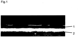
- Fig.1 a light micrograph (incident light) of the cross section of a substrate 2 coated with a single-phase layer 1 of an intermetallic compound of the type Al 13 Fe 4.
- the layer thickness is approximately 270 nm.
- the method according to the embodiment for producing a single-phase layer of intermetallic compounds of the type Al 13 Fe 4 on a structured metal foil as a substrate includes the following procedural steps: - Provision of a substrate made of an iron-based alloy (material number 1.4435) - Optional cleaning of the substrate in an ultrasonic bath in ethanol. - Optional heating of the substrate, preferably at 650°C in air, whereby an oxide adhesion promoter layer forms on the surface to be coated. - Positioning the substrate in a process chamber of a DC magnetron sputtering system, with a cathode with a surface made of the intermetallic compound Al 13 Fe 4 facing the substrate being arranged in the process chamber.
- the substrate was fixed to a substrate holder with retaining clips so that the substrate holder and the target (cathode) were parallel to each other during the subsequent coating process.
- the distance between the two was approximately 6 cm in the exemplary embodiment.
- This step preferably takes place after the substrates have been installed and the process chamber has been evacuated.
- Evacuation of the process chamber preferably to 3.9 ⁇ 10 -4 Pa.
- Optional heating of the process chamber preferably for 30 minutes, to a temperature between 200°C and 500°C.
- the process chamber was heated during evacuation, it will be cooled to room temperature in the evacuated state.
- H 2 glow discharge is used to clean the surfaces of the process chamber, the substrate and the target.
- a hydrogen plasma is generated, whereby the substrate with the substrate holder in the sample chamber performs a rotational movement and passes through the plasma.
- the process chamber is evacuated.
- argon is introduced into the process chamber and an argon plasma is generated.
- the material components of the cathodes are simultaneously transferred into a plasma and the material components are simultaneously deposited on the surface of the aperture.
- the ignited argon plasma is maintained and the aperture between the substrate and target is removed so that the material components from the plasma are simultaneously deposited to form a layer of the intermetallic compound Al 13 Fe 4 with a single-phase structure on the substrate. This is supported by applying a BIAS voltage to the substrate.
- the measured voltage during the sputtering process was 641 V with a deviation of less than 0.5%.
- the target was cooled from the back with cooling water (16°C).
- the process chamber was not heated.
- the deposition rates of the Al 13 Fe 4 target were determined in preliminary tests. Therefore, the process parameters were selected so that a deposition rate of about 7 nm per minute was achieved and thus the expected layer thickness after 40 minutes of sputtering was 270 nm.
Landscapes
- Chemical & Material Sciences (AREA)
- Engineering & Computer Science (AREA)
- Chemical Kinetics & Catalysis (AREA)
- Materials Engineering (AREA)
- Mechanical Engineering (AREA)
- Metallurgy (AREA)
- Organic Chemistry (AREA)
- Physics & Mathematics (AREA)
- Plasma & Fusion (AREA)
- Analytical Chemistry (AREA)
- Physical Vapour Deposition (AREA)
Claims (10)
- Procédé de réalisation d'une couche monophasée (1) de liaisons intermétalliques sur un substrat (2) consistant à :a) fournir un substrat,b) installer le substrat dans une chambre de traitement d'une installation de pulvérisation magnétron DC et faire le vide dans la chambre de traitement,* la chambre de traitement ayant au moins une cathode à surface tournée vers le substrat en une liaison intermétallique,c) transférer simultanément des composants de la matière de la cathode dans un plasma en utilisant un gaz noble comme gaz de pulvérisation,d) séparer simultanément les composants de matière du plasma en une couche intermétallique avec un réseau monophasé sur le substrat, ete) enlever le substrat avec la couche intermétallique déposée de la chambre de procédé,
procédé selon lequelf) la liaison intermétallique d'au moins une cathode est monophasée et cela jusque dans le domaine atomique,g) la couche monophasée peut comporter également d'autres phases possibles, par exemple, provenant d'impuretés mais qui ne sont pas composées des combinaisons élémentaires de la liaison intermétallique,h) la liaison intermétallique est une liaison intermétallique de type GaxPdy ou Al13Fe4 et la couche intermétallique est une couche de type GaxPdy ou Al13Fe4, eti) le caractère monophasé de la couche métallique, déposée peut être contrôlée par une analyse de structure aux rayons X (XRD), reproduisant la composition de la phase dans des diagrammes de diffraction,* le caractère monophasé étant prouvé par l'apparition exclusive des reflets caractéristiques dans le diffractogramme. - Procédé selon la revendication 1,caractérisé en ce queGaxPdy est formé par GaPd2.
- Procédé selon l'une des revendications 1 ou 2,
comprenant :
la réalisation de cathodes avec un procédé de frittage à partir d'une poudre intermétallique provenant de la liaison intermétallique. - Procédé selon la revendication 3,
caractérisé en ce que
la poudre intermétallique est synthétisée de manière monophasée. - Procédé selon la revendication 4,
caractérisé en ce que
la poudre intermétallique synthétisée de manière monophasée est obtenue par une synthèse de corps solides. - Procédé selon l'une des revendications 3 à 5,
caractérisé en ce que
le procédé de frittage est un procédé de frittage SPS. - Procédé selon l'une des revendications précédentes,
caractérisé en ce que
au moins l'une des cathodes est en un corps de base métallique et l'une des couches appliquées par frittage est une liaison intermétallique à déposer. - Procédé selon la revendication 7,
caractérisé en ce que
le corps de base est en cuivre ou en argent. - Procédé selon l'une des revendications précédentes,
caractérisé en ce que
le substrat avec la couche intermétallique déposée est dégagé à une température comprise entre 300 et 850°C. - Procédé selon l'une des revendications précédentes,
caractérisé en ce que
le substrat est en un métal qui, avant le placement du substrat dans une chambre de traitement d'une installation de pulvérisation magnétron DC, pour former une couche d'oxyde adhésive sur le substrat est à une température comprise entre 600 et 700°C.
Applications Claiming Priority (2)
| Application Number | Priority Date | Filing Date | Title |
|---|---|---|---|
| DE102017116972.5A DE102017116972A1 (de) | 2017-07-27 | 2017-07-27 | Verfahren zur Herstellung einer einphasigen Schicht aus intermetallischen Verbindungen |
| PCT/EP2018/000371 WO2019020214A1 (fr) | 2017-07-27 | 2018-07-25 | Procédé pour la préparation d'une couche à phase unique en composés intermétalliques |
Publications (2)
| Publication Number | Publication Date |
|---|---|
| EP3658698A1 EP3658698A1 (fr) | 2020-06-03 |
| EP3658698B1 true EP3658698B1 (fr) | 2024-08-28 |
Family
ID=63113462
Family Applications (1)
| Application Number | Title | Priority Date | Filing Date |
|---|---|---|---|
| EP18750326.3A Active EP3658698B1 (fr) | 2017-07-27 | 2018-07-25 | Procédé de fabrication d'une couche monophasée en composé intermétallique |
Country Status (3)
| Country | Link |
|---|---|
| EP (1) | EP3658698B1 (fr) |
| DE (1) | DE102017116972A1 (fr) |
| WO (1) | WO2019020214A1 (fr) |
Families Citing this family (1)
| Publication number | Priority date | Publication date | Assignee | Title |
|---|---|---|---|---|
| CN111318801B (zh) * | 2020-03-09 | 2021-07-20 | 中南大学 | 一种基于高熵合金扩散焊接的金属间化合物及其制备方法 |
Family Cites Families (10)
| Publication number | Priority date | Publication date | Assignee | Title |
|---|---|---|---|---|
| US5171642A (en) * | 1989-04-17 | 1992-12-15 | International Business Machines Corporation | Multilayered intermetallic connection for semiconductor devices |
| US6258719B1 (en) * | 1998-07-01 | 2001-07-10 | Honeywell International Inc. | Intermetallic aluminides and silicides articles, such as sputtering targets, and methods of making same |
| JP2989169B2 (ja) * | 1997-08-08 | 1999-12-13 | 日立金属株式会社 | Ni−Al系金属間化合物ターゲットおよびその製造方法ならびに磁気記録媒体 |
| JPH11175947A (ja) * | 1997-12-12 | 1999-07-02 | Hitachi Metals Ltd | 磁気記録媒体および下地層形成用ターゲット |
| DE10044526A1 (de) | 2000-09-04 | 2002-04-04 | Mannesmann Ag | Mikrostrukturreaktor und Verfahren zur Durchführung chemischer Reaktionen |
| AT414128B (de) * | 2004-08-03 | 2006-09-15 | Miba Gleitlager Gmbh | Aluminiumlegierung für tribologisch beanspruchte flächen |
| FR2881757B1 (fr) * | 2005-02-08 | 2007-03-30 | Saint Gobain | Procede d'elaboration par projection thermique d'une cible a base de silicium et de zirconium |
| DE102005022958B3 (de) | 2005-05-19 | 2006-07-20 | Forschungszentrum Karlsruhe Gmbh | Mikrostrukturreaktor und Verwendung desselben |
| DE102012100344A1 (de) | 2012-01-17 | 2013-07-18 | Karlsruher Institut für Technologie | Mikroreaktor für katalytische Reaktionen |
| JP5594618B1 (ja) * | 2013-02-25 | 2014-09-24 | 三菱マテリアル株式会社 | スパッタリングターゲット及びその製造方法 |
-
2017
- 2017-07-27 DE DE102017116972.5A patent/DE102017116972A1/de not_active Ceased
-
2018
- 2018-07-25 EP EP18750326.3A patent/EP3658698B1/fr active Active
- 2018-07-25 WO PCT/EP2018/000371 patent/WO2019020214A1/fr not_active Ceased
Also Published As
| Publication number | Publication date |
|---|---|
| EP3658698A1 (fr) | 2020-06-03 |
| WO2019020214A1 (fr) | 2019-01-31 |
| DE102017116972A1 (de) | 2019-01-31 |
Similar Documents
| Publication | Publication Date | Title |
|---|---|---|
| DE60034513T2 (de) | Verfahren zur Herstellung eines Sputtertargets | |
| DE69706643T2 (de) | Verfahren zur herstellung von dünnen schichten eines nicht verdampfbaren gettermaterials auf einem träger | |
| DE102015100665B4 (de) | Verfahren zum Erzeugen einer Metallschicht auf einem Halbleiterkörper unter Verwendung eines Druckprozesses | |
| DE69814560T2 (de) | Nickelpulver und Verfahren zu seiner Herstellung | |
| EP2845920A1 (fr) | Composés d'oxydes utilisés comme compositions de revêtement | |
| EP3347303B1 (fr) | Procédé de production de surfaces structurées | |
| DE2252343A1 (de) | Verfahren zur herstellung von kuenstlichen diamanten | |
| DE102012217191A1 (de) | Herstellen eines Refraktärmetall-Bauteils | |
| EP3308417B1 (fr) | Procédé de fabrication de couches nano-structurées | |
| DE102007049930B4 (de) | Oberflächenmodifizierte Hohlraumstrukturen, Verfahren zu deren Herstellung sowie deren Verwendung | |
| DE3602804C2 (fr) | ||
| DE19928807B4 (de) | Verfahren zur Herstellung eines piezoelektrischen/elektrostriktiven Keramik-Mikro-Stellgliedes unter Verwendung von Photolithographie | |
| DE3029171A1 (de) | Verfahren zur herstellung von poroesen metallfilmen | |
| EP0033506B1 (fr) | Procédé pour la fabrication de feuilles monocristallines de valeur ohmique faible en métal ou en alliage métallique fixées sur supports isolants | |
| EP4112587A1 (fr) | Procédé de fabrication d'un substrat métal-céramique par chauffage rapide | |
| EP3172354B1 (fr) | Cible de pulvérisation cathodique à base d'un alliage d'argent | |
| DE102017116972A1 (de) | Verfahren zur Herstellung einer einphasigen Schicht aus intermetallischen Verbindungen | |
| EP1250192A2 (fr) | Catalyseurs a couche mince a base d'alliages de type raney et procede permettant de les produire | |
| EP3823779A1 (fr) | Utilisation de poudres de métaux hautement réfléchissants pour la fabrication additive | |
| WO2024002788A1 (fr) | Procédé de fabrication d'un composant électrique au moyen de l'impression et du frittage successifs d'encre contenant des particules | |
| DE69115854T2 (de) | Rost zur thermischen Behandlung mit hoher Temperatur | |
| EP0537501B1 (fr) | Méthode de fabrication de composant électroniques composés de couches conductrices et non-conductrices | |
| DE102019130583A1 (de) | Verfahren zur herstellung eines brennstoffzellenseparators | |
| DE102023209672B3 (de) | Elektrode für elektrochemische Zellen | |
| DE102012111807A1 (de) | Verfahren zur Herstellung von Nanostrukturen |
Legal Events
| Date | Code | Title | Description |
|---|---|---|---|
| STAA | Information on the status of an ep patent application or granted ep patent |
Free format text: STATUS: UNKNOWN |
|
| STAA | Information on the status of an ep patent application or granted ep patent |
Free format text: STATUS: THE INTERNATIONAL PUBLICATION HAS BEEN MADE |
|
| PUAI | Public reference made under article 153(3) epc to a published international application that has entered the european phase |
Free format text: ORIGINAL CODE: 0009012 |
|
| STAA | Information on the status of an ep patent application or granted ep patent |
Free format text: STATUS: REQUEST FOR EXAMINATION WAS MADE |
|
| 17P | Request for examination filed |
Effective date: 20191213 |
|
| AK | Designated contracting states |
Kind code of ref document: A1 Designated state(s): AL AT BE BG CH CY CZ DE DK EE ES FI FR GB GR HR HU IE IS IT LI LT LU LV MC MK MT NL NO PL PT RO RS SE SI SK SM TR |
|
| AX | Request for extension of the european patent |
Extension state: BA ME |
|
| DAV | Request for validation of the european patent (deleted) | ||
| DAX | Request for extension of the european patent (deleted) | ||
| RIN1 | Information on inventor provided before grant (corrected) |
Inventor name: ZIMMERMANN, RENE Inventor name: ARMBRUESTER, MARC Inventor name: SIEBERT, MARTIN Inventor name: DITTMEYER, ROLAND |
|
| STAA | Information on the status of an ep patent application or granted ep patent |
Free format text: STATUS: EXAMINATION IS IN PROGRESS |
|
| 17Q | First examination report despatched |
Effective date: 20210928 |
|
| GRAP | Despatch of communication of intention to grant a patent |
Free format text: ORIGINAL CODE: EPIDOSNIGR1 |
|
| STAA | Information on the status of an ep patent application or granted ep patent |
Free format text: STATUS: GRANT OF PATENT IS INTENDED |
|
| RIC1 | Information provided on ipc code assigned before grant |
Ipc: B22F 3/24 20060101ALN20240419BHEP Ipc: B22F 3/105 20060101ALN20240419BHEP Ipc: B22F 7/06 20060101ALN20240419BHEP Ipc: C22C 1/04 20060101ALN20240419BHEP Ipc: H01J 37/34 20060101ALI20240419BHEP Ipc: C23C 14/34 20060101ALI20240419BHEP Ipc: C23C 14/35 20060101ALI20240419BHEP Ipc: C23C 14/16 20060101AFI20240419BHEP |
|
| INTG | Intention to grant announced |
Effective date: 20240522 |
|
| RIN1 | Information on inventor provided before grant (corrected) |
Inventor name: ZIMMERMANN, RENE Inventor name: ARMBRUESTER, MARC Inventor name: SIEBERT, MARTIN Inventor name: DITTMEYER, ROLAND |
|
| GRAS | Grant fee paid |
Free format text: ORIGINAL CODE: EPIDOSNIGR3 |
|
| GRAA | (expected) grant |
Free format text: ORIGINAL CODE: 0009210 |
|
| STAA | Information on the status of an ep patent application or granted ep patent |
Free format text: STATUS: THE PATENT HAS BEEN GRANTED |
|
| AK | Designated contracting states |
Kind code of ref document: B1 Designated state(s): AL AT BE BG CH CY CZ DE DK EE ES FI FR GB GR HR HU IE IS IT LI LT LU LV MC MK MT NL NO PL PT RO RS SE SI SK SM TR |
|
| REG | Reference to a national code |
Ref country code: GB Ref legal event code: FG4D Free format text: NOT ENGLISH |
|
| REG | Reference to a national code |
Ref country code: DE Ref legal event code: R081 Ref document number: 502018015063 Country of ref document: DE Owner name: KARLSRUHER INSTITUT FUER TECHNOLOGIE, KOERPERS, DE Free format text: FORMER OWNER: ANMELDERANGABEN UNKLAR / UNVOLLSTAENDIG, 80297 MUENCHEN, DE |
|
| REG | Reference to a national code |
Ref country code: CH Ref legal event code: EP |
|
| REG | Reference to a national code |
Ref country code: DE Ref legal event code: R096 Ref document number: 502018015063 Country of ref document: DE |
|
| REG | Reference to a national code |
Ref country code: IE Ref legal event code: FG4D Free format text: LANGUAGE OF EP DOCUMENT: GERMAN |
|
| REG | Reference to a national code |
Ref country code: LT Ref legal event code: MG9D |
|
| PG25 | Lapsed in a contracting state [announced via postgrant information from national office to epo] |
Ref country code: NO Free format text: LAPSE BECAUSE OF FAILURE TO SUBMIT A TRANSLATION OF THE DESCRIPTION OR TO PAY THE FEE WITHIN THE PRESCRIBED TIME-LIMIT Effective date: 20241128 |
|
| PG25 | Lapsed in a contracting state [announced via postgrant information from national office to epo] |
Ref country code: PT Free format text: LAPSE BECAUSE OF FAILURE TO SUBMIT A TRANSLATION OF THE DESCRIPTION OR TO PAY THE FEE WITHIN THE PRESCRIBED TIME-LIMIT Effective date: 20241230 Ref country code: NL Free format text: LAPSE BECAUSE OF FAILURE TO SUBMIT A TRANSLATION OF THE DESCRIPTION OR TO PAY THE FEE WITHIN THE PRESCRIBED TIME-LIMIT Effective date: 20240828 Ref country code: PL Free format text: LAPSE BECAUSE OF FAILURE TO SUBMIT A TRANSLATION OF THE DESCRIPTION OR TO PAY THE FEE WITHIN THE PRESCRIBED TIME-LIMIT Effective date: 20240828 Ref country code: FI Free format text: LAPSE BECAUSE OF FAILURE TO SUBMIT A TRANSLATION OF THE DESCRIPTION OR TO PAY THE FEE WITHIN THE PRESCRIBED TIME-LIMIT Effective date: 20240828 Ref country code: GR Free format text: LAPSE BECAUSE OF FAILURE TO SUBMIT A TRANSLATION OF THE DESCRIPTION OR TO PAY THE FEE WITHIN THE PRESCRIBED TIME-LIMIT Effective date: 20241129 |
|
| PG25 | Lapsed in a contracting state [announced via postgrant information from national office to epo] |
Ref country code: BG Free format text: LAPSE BECAUSE OF FAILURE TO SUBMIT A TRANSLATION OF THE DESCRIPTION OR TO PAY THE FEE WITHIN THE PRESCRIBED TIME-LIMIT Effective date: 20240828 |
|
| PG25 | Lapsed in a contracting state [announced via postgrant information from national office to epo] |
Ref country code: LV Free format text: LAPSE BECAUSE OF FAILURE TO SUBMIT A TRANSLATION OF THE DESCRIPTION OR TO PAY THE FEE WITHIN THE PRESCRIBED TIME-LIMIT Effective date: 20240828 |
|
| REG | Reference to a national code |
Ref country code: NL Ref legal event code: MP Effective date: 20240828 |
|
| PG25 | Lapsed in a contracting state [announced via postgrant information from national office to epo] |
Ref country code: IS Free format text: LAPSE BECAUSE OF FAILURE TO SUBMIT A TRANSLATION OF THE DESCRIPTION OR TO PAY THE FEE WITHIN THE PRESCRIBED TIME-LIMIT Effective date: 20241228 |
|
| PG25 | Lapsed in a contracting state [announced via postgrant information from national office to epo] |
Ref country code: HR Free format text: LAPSE BECAUSE OF FAILURE TO SUBMIT A TRANSLATION OF THE DESCRIPTION OR TO PAY THE FEE WITHIN THE PRESCRIBED TIME-LIMIT Effective date: 20240828 |
|
| PG25 | Lapsed in a contracting state [announced via postgrant information from national office to epo] |
Ref country code: RS Free format text: LAPSE BECAUSE OF FAILURE TO SUBMIT A TRANSLATION OF THE DESCRIPTION OR TO PAY THE FEE WITHIN THE PRESCRIBED TIME-LIMIT Effective date: 20241128 Ref country code: ES Free format text: LAPSE BECAUSE OF FAILURE TO SUBMIT A TRANSLATION OF THE DESCRIPTION OR TO PAY THE FEE WITHIN THE PRESCRIBED TIME-LIMIT Effective date: 20240828 |
|
| PG25 | Lapsed in a contracting state [announced via postgrant information from national office to epo] |
Ref country code: RS Free format text: LAPSE BECAUSE OF FAILURE TO SUBMIT A TRANSLATION OF THE DESCRIPTION OR TO PAY THE FEE WITHIN THE PRESCRIBED TIME-LIMIT Effective date: 20241128 Ref country code: PT Free format text: LAPSE BECAUSE OF FAILURE TO SUBMIT A TRANSLATION OF THE DESCRIPTION OR TO PAY THE FEE WITHIN THE PRESCRIBED TIME-LIMIT Effective date: 20241230 Ref country code: PL Free format text: LAPSE BECAUSE OF FAILURE TO SUBMIT A TRANSLATION OF THE DESCRIPTION OR TO PAY THE FEE WITHIN THE PRESCRIBED TIME-LIMIT Effective date: 20240828 Ref country code: NO Free format text: LAPSE BECAUSE OF FAILURE TO SUBMIT A TRANSLATION OF THE DESCRIPTION OR TO PAY THE FEE WITHIN THE PRESCRIBED TIME-LIMIT Effective date: 20241128 Ref country code: NL Free format text: LAPSE BECAUSE OF FAILURE TO SUBMIT A TRANSLATION OF THE DESCRIPTION OR TO PAY THE FEE WITHIN THE PRESCRIBED TIME-LIMIT Effective date: 20240828 Ref country code: LV Free format text: LAPSE BECAUSE OF FAILURE TO SUBMIT A TRANSLATION OF THE DESCRIPTION OR TO PAY THE FEE WITHIN THE PRESCRIBED TIME-LIMIT Effective date: 20240828 Ref country code: IS Free format text: LAPSE BECAUSE OF FAILURE TO SUBMIT A TRANSLATION OF THE DESCRIPTION OR TO PAY THE FEE WITHIN THE PRESCRIBED TIME-LIMIT Effective date: 20241228 Ref country code: HR Free format text: LAPSE BECAUSE OF FAILURE TO SUBMIT A TRANSLATION OF THE DESCRIPTION OR TO PAY THE FEE WITHIN THE PRESCRIBED TIME-LIMIT Effective date: 20240828 Ref country code: GR Free format text: LAPSE BECAUSE OF FAILURE TO SUBMIT A TRANSLATION OF THE DESCRIPTION OR TO PAY THE FEE WITHIN THE PRESCRIBED TIME-LIMIT Effective date: 20241129 Ref country code: FI Free format text: LAPSE BECAUSE OF FAILURE TO SUBMIT A TRANSLATION OF THE DESCRIPTION OR TO PAY THE FEE WITHIN THE PRESCRIBED TIME-LIMIT Effective date: 20240828 Ref country code: ES Free format text: LAPSE BECAUSE OF FAILURE TO SUBMIT A TRANSLATION OF THE DESCRIPTION OR TO PAY THE FEE WITHIN THE PRESCRIBED TIME-LIMIT Effective date: 20240828 Ref country code: BG Free format text: LAPSE BECAUSE OF FAILURE TO SUBMIT A TRANSLATION OF THE DESCRIPTION OR TO PAY THE FEE WITHIN THE PRESCRIBED TIME-LIMIT Effective date: 20240828 |
|
| PG25 | Lapsed in a contracting state [announced via postgrant information from national office to epo] |
Ref country code: RO Free format text: LAPSE BECAUSE OF FAILURE TO SUBMIT A TRANSLATION OF THE DESCRIPTION OR TO PAY THE FEE WITHIN THE PRESCRIBED TIME-LIMIT Effective date: 20240828 Ref country code: DK Free format text: LAPSE BECAUSE OF FAILURE TO SUBMIT A TRANSLATION OF THE DESCRIPTION OR TO PAY THE FEE WITHIN THE PRESCRIBED TIME-LIMIT Effective date: 20240828 Ref country code: SM Free format text: LAPSE BECAUSE OF FAILURE TO SUBMIT A TRANSLATION OF THE DESCRIPTION OR TO PAY THE FEE WITHIN THE PRESCRIBED TIME-LIMIT Effective date: 20240828 |
|
| PG25 | Lapsed in a contracting state [announced via postgrant information from national office to epo] |
Ref country code: EE Free format text: LAPSE BECAUSE OF FAILURE TO SUBMIT A TRANSLATION OF THE DESCRIPTION OR TO PAY THE FEE WITHIN THE PRESCRIBED TIME-LIMIT Effective date: 20240828 |
|
| PG25 | Lapsed in a contracting state [announced via postgrant information from national office to epo] |
Ref country code: CZ Free format text: LAPSE BECAUSE OF FAILURE TO SUBMIT A TRANSLATION OF THE DESCRIPTION OR TO PAY THE FEE WITHIN THE PRESCRIBED TIME-LIMIT Effective date: 20240828 |
|
| PG25 | Lapsed in a contracting state [announced via postgrant information from national office to epo] |
Ref country code: SK Free format text: LAPSE BECAUSE OF FAILURE TO SUBMIT A TRANSLATION OF THE DESCRIPTION OR TO PAY THE FEE WITHIN THE PRESCRIBED TIME-LIMIT Effective date: 20240828 Ref country code: IT Free format text: LAPSE BECAUSE OF FAILURE TO SUBMIT A TRANSLATION OF THE DESCRIPTION OR TO PAY THE FEE WITHIN THE PRESCRIBED TIME-LIMIT Effective date: 20240828 |
|
| REG | Reference to a national code |
Ref country code: DE Ref legal event code: R097 Ref document number: 502018015063 Country of ref document: DE |
|
| PLBE | No opposition filed within time limit |
Free format text: ORIGINAL CODE: 0009261 |
|
| STAA | Information on the status of an ep patent application or granted ep patent |
Free format text: STATUS: NO OPPOSITION FILED WITHIN TIME LIMIT |
|
| 26N | No opposition filed |
Effective date: 20250530 |
|
| PG25 | Lapsed in a contracting state [announced via postgrant information from national office to epo] |
Ref country code: SE Free format text: LAPSE BECAUSE OF FAILURE TO SUBMIT A TRANSLATION OF THE DESCRIPTION OR TO PAY THE FEE WITHIN THE PRESCRIBED TIME-LIMIT Effective date: 20240828 |
|
| PGFP | Annual fee paid to national office [announced via postgrant information from national office to epo] |
Ref country code: DE Payment date: 20250722 Year of fee payment: 8 |
|
| PGFP | Annual fee paid to national office [announced via postgrant information from national office to epo] |
Ref country code: GB Payment date: 20250724 Year of fee payment: 8 |
|
| PGFP | Annual fee paid to national office [announced via postgrant information from national office to epo] |
Ref country code: FR Payment date: 20250723 Year of fee payment: 8 Ref country code: AT Payment date: 20250721 Year of fee payment: 8 |
|
| PGFP | Annual fee paid to national office [announced via postgrant information from national office to epo] |
Ref country code: CH Payment date: 20250801 Year of fee payment: 8 |
|
| PG25 | Lapsed in a contracting state [announced via postgrant information from national office to epo] |
Ref country code: LU Free format text: LAPSE BECAUSE OF NON-PAYMENT OF DUE FEES Effective date: 20250725 |
|
| REG | Reference to a national code |
Ref country code: BE Ref legal event code: MM Effective date: 20250731 |
|
| REG | Reference to a national code |
Ref country code: CH Ref legal event code: R17 Free format text: ST27 STATUS EVENT CODE: U-0-0-R10-R17 (AS PROVIDED BY THE NATIONAL OFFICE) Effective date: 20260410 |
|
| PG25 | Lapsed in a contracting state [announced via postgrant information from national office to epo] |
Ref country code: BE Free format text: LAPSE BECAUSE OF NON-PAYMENT OF DUE FEES Effective date: 20250731 |