EP3658706B1 - Geflochtene textilhülse mit verschlossenen fäden und verfahren zu ihrer konstruktion - Google Patents
Geflochtene textilhülse mit verschlossenen fäden und verfahren zu ihrer konstruktion Download PDFInfo
- Publication number
- EP3658706B1 EP3658706B1 EP18753009.2A EP18753009A EP3658706B1 EP 3658706 B1 EP3658706 B1 EP 3658706B1 EP 18753009 A EP18753009 A EP 18753009A EP 3658706 B1 EP3658706 B1 EP 3658706B1
- Authority
- EP
- European Patent Office
- Prior art keywords
- activatable
- yarns
- yarn
- heat
- another
- Prior art date
- Legal status (The legal status is an assumption and is not a legal conclusion. Google has not performed a legal analysis and makes no representation as to the accuracy of the status listed.)
- Active
Links
Images


Classifications
-
- D—TEXTILES; PAPER
- D04—BRAIDING; LACE-MAKING; KNITTING; TRIMMINGS; NON-WOVEN FABRICS
- D04C—BRAIDING OR MANUFACTURE OF LACE, INCLUDING BOBBIN-NET OR CARBONISED LACE; BRAIDING MACHINES; BRAID; LACE
- D04C1/00—Braid or lace, e.g. pillow-lace; Processes for the manufacture thereof
- D04C1/06—Braid or lace serving particular purposes
-
- D—TEXTILES; PAPER
- D04—BRAIDING; LACE-MAKING; KNITTING; TRIMMINGS; NON-WOVEN FABRICS
- D04C—BRAIDING OR MANUFACTURE OF LACE, INCLUDING BOBBIN-NET OR CARBONISED LACE; BRAIDING MACHINES; BRAID; LACE
- D04C1/00—Braid or lace, e.g. pillow-lace; Processes for the manufacture thereof
- D04C1/02—Braid or lace, e.g. pillow-lace; Processes for the manufacture thereof made from particular materials
-
- D—TEXTILES; PAPER
- D07—ROPES; CABLES OTHER THAN ELECTRIC
- D07B—ROPES OR CABLES IN GENERAL
- D07B2201/00—Ropes or cables
- D07B2201/20—Rope or cable components
- D07B2201/2083—Jackets or coverings
- D07B2201/209—Jackets or coverings comprising braided structures
-
- D—TEXTILES; PAPER
- D10—INDEXING SCHEME ASSOCIATED WITH SUBLASSES OF SECTION D, RELATING TO TEXTILES
- D10B—INDEXING SCHEME ASSOCIATED WITH SUBLASSES OF SECTION D, RELATING TO TEXTILES
- D10B2401/00—Physical properties
- D10B2401/04—Heat-responsive characteristics
- D10B2401/041—Heat-responsive characteristics thermoplastic; thermosetting
-
- D—TEXTILES; PAPER
- D10—INDEXING SCHEME ASSOCIATED WITH SUBLASSES OF SECTION D, RELATING TO TEXTILES
- D10B—INDEXING SCHEME ASSOCIATED WITH SUBLASSES OF SECTION D, RELATING TO TEXTILES
- D10B2403/00—Details of fabric structure established in the fabric forming process
- D10B2403/03—Shape features
- D10B2403/033—Three dimensional fabric, e.g. forming or comprising cavities in or protrusions from the basic planar configuration, or deviations from the cylindrical shape as generally imposed by the fabric forming process
- D10B2403/0333—Three dimensional fabric, e.g. forming or comprising cavities in or protrusions from the basic planar configuration, or deviations from the cylindrical shape as generally imposed by the fabric forming process with tubular portions of variable diameter or distinct axial orientation
-
- D—TEXTILES; PAPER
- D10—INDEXING SCHEME ASSOCIATED WITH SUBLASSES OF SECTION D, RELATING TO TEXTILES
- D10B—INDEXING SCHEME ASSOCIATED WITH SUBLASSES OF SECTION D, RELATING TO TEXTILES
- D10B2505/00—Industrial
- D10B2505/12—Vehicles
Definitions
- This invention relates generally to textile sleeves, and more particularly to braided textile sleeves.
- Braided sleeves commonly have a wall braided as a circumferentially continuous, seamless wall, sometimes referred to as a 'closed' wall.
- a closed, braided wall construction is that the wall can be circumferentially expanded to facilitate sliding the wall over an elongated member by manually pushing and physically holding the opposite ends of the wall in a compressed fashion. By pushing the opposite ends toward one another and manually holding the wall in an axially compressed state, the braided wall is caused to take on an increased diameter and a reduced length. When in the increased diameter state, the wall can be readily disposed over the elongate member.
- tape is commonly wrapped about at least a portion of the sleeve to prevent the yarns from shifting and expanding, thereby fixing the sleeve in the desired location.
- the tape is also typically adhered to an outer surface of the elongate member being protected by the sleeve to further fix the sleeve in its desired location.
- the aforementioned ability to fix the yarns of the braided wall in their intended location and to fix the sleeve in an intended location on the elongate member via tape comes with potential drawbacks.
- the tape must be purchased separately and inventoried, thereby adding cost to the application.
- the tape can become damaged and/or contaminated during assembly and while in use, thereby affecting its ability to maintain the yarns and the sleeve in their intended fixed location.
- the tape can be unsightly upon application, or can otherwise become unsightly over time.
- application of tape can be labor intensive, thereby adding further cost to the application.
- An example of a fabric sleeve is disclosed in document WO 2016/010730 A1 .
- the sleeve includes a wall extending along a longitudinal axis between opposite ends.
- the wall is formed from a plurality of filaments interlaced with one another, with at least one of the filaments being provided as a continuous strand of conductive wire and at least some of the filaments being provided as heat-fusible nonconductive filaments.
- Document US 2016/122915 A1 discloses a protective textile sleeve including a braided, tubular wall.
- the wall has a decreased length, increased diameter first state and an increased length, decreased diameter second state and heat-set, braided yarns within the wall impart a bias on the wall.
- Document US 2017/167062 A1 discloses a braided textile sleeve having a flexible, seamless, reflective tubular wall including a first set of yarns and a second set of yarns braided with one another.
- the first and second yarns are provided as different types of yarns from one another and are braided in opposite helical directions with one another and a third set of yarns captured between the first and second sets of yarns.
- a protective textile sleeve includes a seamless, circumferentially continuous, tubular braided wall extending lengthwise along a central longitudinal axis between opposite ends.
- the wall includes a plurality of yarns braided with one another, with at least one or more of the yarns being an activatable adhesive yarn to bond the yarns in fixed relation with one another, upon selective activation of the at least one activatable yarn, to inhibit the expansion of the braided wall upon being activated, thereby maintaining the wall in the desired confirmation upon assembly without the need for secondary fixation mechanisms.
- the at least one activatable yarn includes a heat-fusible yarn provided to melt and solidify and bond abutting ones of said yarns with one another and a heat-shrinkable yarn.
- the braided yarns in addition to the activatable yarns, can non-heat-shrinkable yarns, with the heat-shrinkable yarns being oriented relative to the non-heat-shrinkable yarns to facilitate locking the yarns relative to one another upon the heat-shrinkable yarns being shrunken.
- the activatable yarns are heat-activatable.
- the heat-fusible yarn can be bicomponent filaments including a core and an activatable outer sheath, wherein the outer sheath can be a hot melt material, wherein the hot melt material has a lower melt temperature than the core, such that when the outer sheath is melt, the core remains unmelted to provide stability and structure to the sleeve.
- the bicomponent can be provided wherein the inner core is heat-settable, and wherein the outer sheath and the inner core are activatable to melt and heat-set, respectively, at the same temperature.
- the at least one activatable yarn includes a heat-fusible yarn (such as being constructed at least in part via a hot melt material) provided to melt and solidify and bond abutting ones of said yarns with one another.
- a heat-fusible yarn such as being constructed at least in part via a hot melt material
- the wall can include non-activatable yarn, with low melt yarn having a lower melt temperature than the non-activatable yarn.
- the at least one activatable yarn and the non-activatable yarn can be provided in an equal number of ends with one another.
- the activatable yarns and the non-activatable yarns can be braided in a respective 1:1 braid pattern, with the activatable yarns and the non-activatable yarns alternating with one another in opposite S and Z helical directions.
- the activatable yarns and the non-activatable yarns can be braided in a respective 1:2 braid pattern, with the activatable yarns and the non-activatable yarns alternating with one another in opposite S and Z helical directions, thus reducing the more costly content of the activatable yarn relative to the non-activatable yarn and enhancing flexibility of the sleeve by reducing the amount of melted and solidified material, relative to a sleeve having a greater content of activatable yarn.
- the activatable yarns and the non-activatable yarns can be braided in a respective 1:3 braid pattern, with the activatable yarns and the non-activatable yarns alternating with one another in opposite S and Z helical directions.
- the activatable yarns and the non-activatable yarns can be braided in a respective 2:1 braid pattern, with the activatable yarns and the non-activatable yarns alternating with one another in opposite S and Z helical directions, thereby providing an enhanced bond force between the yarns by providing a greater number of activatable yarns relative to non-activatable yarns.
- the activatable yarns and the non-activatable yarns can be braided in a respective 3:1 braid pattern, with the activatable yarns and the non-activatable yarns alternating with one another in opposite S and Z helical directions.
- a protective textile sleeve which does not form part of the invention, and in which, the entirety of the yarns can include a low melt material provided to melt and solidify and bond abutting ones of the yarns with one another.
- At least one of the yarns of the sleeve can be provided as being a non-activatable monofilament and/or multifilament, as desired to provide the sleeve with the desire type of protection and flexibility.
- a method of constructing a braided textile sleeve includes braiding a plurality of yarns with one another to form a seamless tubular wall extending lengthwise along a central longitudinal axis, with at least some of the yarns being provided as activatable yarns, which, upon being activated, bond with and lock the yarns of the sleeve relative to one another, thereby maintaining the wall in the desired configuration upon assembly without the need for secondary fixation mechanisms.
- the method includes providing at least one or more of the braided activatable yarns as heat-fusible yarn (referred to herein as a low melt yarn), such as formed at least in part including an exposed hot melt material, and a heat-shrinkable yarn.
- the low melt yarn selectively melts and solidifies and bonds abutting ones of the yarns with one another upon applying a suitable heat source thereto.
- the method can further include providing yarns as non-heat-shrinkable yarns, with the heat-shrinkable yarns being oriented relative to the non-heat-shrinkable yarns to facilitate locking the yarns relative to one another upon the heat-shrinkable yarns being shrunken.
- the method can further include braiding the heat-shrinkable yarns and the non-heat-shrinkable yarns in alternating relation with one another in both S and opposite Z helical directions about the circumference of the sleeve to provide the sleeve with a substantially balanced content of the heat-shrinkable yarns and the non-heat-shrinkable yarns.
- the method can further include providing the activatable yarns as at least one of UV activatable yarns, heat-activatable yarns, or chemically activatable yarns.
- the method can further include providing the low melt activatable yarns as bicomponent filaments including a core and an activatable outer sheath, wherein the outer sheath can be a hot melt material having a lower melt temperature than the core.
- the method can further include providing the core being heat-settable at the same temperature used to melt the outer sheath.
- the method can further include braiding the at least one activatable yarn and the non-activatable yarn in an equal number of ends with one another.
- the method can further include braiding the activatable yarns and the non-activatable yarns in a respective 1:1 braid pattern, with the activatable yarns and the non-activatable yarns alternating with one another in opposite S and Z helical directions.
- the method can further include braiding the activatable yarns and the non-activatable yarns in a respective 1:2 braid pattern, with the activatable yarns and the non-activatable yarns alternating with one another in opposite S and Z helical directions.
- the method can further include braiding the activatable yarns and the non-activatable yarns in a respective 1:3 braid pattern, with the activatable yarns and the non-activatable yarns alternating with one another in opposite S and Z helical directions.
- the method can further include braiding the activatable yarns and the non-activatable yarns in a respective 2:1 braid pattern, with the activatable yarns and the non-activatable yarns alternating with one another in opposite S and Z helical directions.
- the method can further include braiding the activatable yarns and the non-activatable yarns in a respective 3:1 braid pattern, with the activatable yarns and the non-activatable yarns alternating with one another in opposite S and Z helical directions.
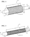
- Figures 1 and 2 illustrate a tubular braided protective textile sleeve, referred to hereafter as sleeve 10, constructed in accordance with one aspect of the invention.
- the sleeve 10 as braided in a single, continuing braiding process, has a braided, circumferentially continuous, seamless tubular wall 12 bounding a through passage, also referred to as cavity 13, extending lengthwise along a central longitudinal axis 14 between open opposite ends 16, 18.
- the wall 12 is axially compressible to attain an assembly, nonactivated first state, wherein a plurality (intended to mean more than 1 yarn and equal to or less than the entirety of the yarns) braided yarns, indicated generally at 20, forming the wall 12 are free to shift, also referred to as slide, relative to one another, such that the nonactivated first state provides the wall 12 having an ability to be axially compressed to a decreased length L1 and increased diameter D1 ( Figure 1 ) via expanded relative movement of the braided yarns 20 and is axially extendible to attain an increased length L2 and decreased diameter D2 ( Figure 2 ) via contracted relative movement of the braided yarns 20.
- the wall 12 While the wall 12 is at least partially or fully biased into the axially compressed, assembly friendly first state, the wall 12 is able to be readily assembled about an elongate member 22 to be protected, with the wall 12, and thus, the cavity 13, having an enlarged diameter relative to the elongate member 22, and then, while in the axially extended second state, at least one or more ends (end, as understood in the art is a single yarn filament) of the braided yarns 20 forming the wall 12 is/are provided as activatable yarn 20', which upon being activated, selectively lock the yarns 20 relative to one another, thereby maintaining and preventing the yarns 20 from shifting relative to one another, and thus, maintaining the wall 12 in its desired assembled configuration (length and diameter) and location relative to the elongate member 22.
- the sleeve 10 is able to remain in its intended, as assembled location along the elongate member 22 without need for secondary fixation mechanisms, such as tape, tie wraps and the like, thereby enhancing assembly efficiencies, reducing cost, and improving the overall appearance of the assembly over the useful life thereof.
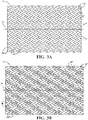
- the braided yarns 20 forming the entirety of the wall 12 can be provided entirely as activatable yarn 20' ( Figure 3A ). Otherwise, as few as one or more of the yarns 20, but less than the entirety, forming the wall 12 can be provided as activatable yarn 20', with the remainder of the yarns 20 being provided as non-activatable yarn 20".
- the activatable yarn 20' is provided as at least a heat-fusible yarn, such as from a hot melt material having a melt temperature less than the melt temperature of the non-activatable yarns 20", and a cross-linked heat-shrinkable yarn (heat-shrinkable is intended to mean yarns that can be activated to shrink 10% or more, up to 90%, of their original, non-activated length).
- the yarns 20 forming a portion of the wall 12 can also include non-activatable yarn 20", and if incorporated, can be provided as any desired type of non-activatable yarn, whether monofilament and/or multifilament, such that the non-activatable yarn 20" is neither readily heat-fusible (not readily capable of being heated to melt and solidify upon being cooled) nor heat-shrinkable (not capable of being shrunken up 10% of their original length).
- the activatable yarn 20' and non-activatable yarn 20" can be provided a desired number of relative ends (an end is known as a single yarn) alternated with one another about the circumference of the sleeve 10 in the opposite S and Z helical directions (S and Z directions illustrated in Figure 3A , as would be understood by a skilled artisan in the textile arts upon viewing the disclosure herein) in any desired respective ratio of ends of activatable yarn 20' to non-activatable yarn 20", such as 1:1 ( Figure 3B ); 1:2 ( Figure 3C ); 1:3 ( Figure 3D ); 3:1 ( Figure 3E ); or 2 :1 ( Figure 3F ), by way of example and without limitation, to provide the sleeve 10 with a substantially circumferentially balanced content of the activatable and non-activatable yarns 20', 20", as desired for the intended application and as needed for the desired strength of fixation of the activatable and non-activatable yarns 20',
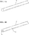
- the activatable yam(s) 20' can be provided as solid, monolithic pieces of a single material filament ( Figure 4A ) and/or as bicomponent filament ( Figure 4B ) including an inner core 24 (activatable, such as being heat-settable to take on a heat-set shape, or non-activatable) and an activatable outer sheath 26 surrounding the inner core 24, wherein the outer sheath 26 can be a hot melt material having a lower melt temperature than the material of the inner core 24, by way of example.
- the sleeve 10 In use, the sleeve 10, with the activatable yarn 20' being braided and initially maintained in a non-activated first state, is disposed about the elongate member 22. While disposing the sleeve 10 about the elongate member 22, the yarns 20', 20" (if provided), are free to move and shift relative to one another, such that the wall 12 is able to be readily compressed axially and expanded radially to provide an enlarged through cavity 13 for the receipt of the elongate member 22 ( Figure 1 ).
- the wall 12 can be axially stretched to take on an axially elongated, radially contracted state, such that the wall 12 is brought into snug or close fit relation about the elongate member 22 ( Figure 2 ).
- the activatable yam(s) 20' can be activated, via application of a suitable heat, via any desired application process, wherein the activated yam(s) 20' is melted and shrunken to lock the entirety of the yarns 20 relative to one another.
- the yarns 20 are bonded with one another via melted and solidified material of the yarns 20', and if shrunken, the friction imparted between the yarns 20 and possibly with the elongate member 22 effectively locks the yarns 20 relative with one another. Accordingly, with the entirety of the yarns 20 being locked relative to one another, the wall 12 is assured of remaining in its intended location on the elongate member 22.
- the inner core 24 is heat-set to retain is helical shape, thereby enhancing radial stiffness and providing the sleeve 10 with an enhanced crush and hoop strength, while the outer sheath 26 is melted and solidified to lock the yarns 20 to one another, as discussed above. It is to be recognized that the activation of the bicomponent yarns 20' can be performed at a single temperature suitable to heat-set the inner core 24 and melt the outer sheath 26.
- a method of constructing a braided textile sleeve 10 includes braiding a plurality of yarns 20 with one another to form a seamless tubular wall 12 extending lengthwise along a central longitudinal axis 14, with at least some of the yarns 20 being provided as activatable yarns 20', which, upon being activated, via application of a source of heat lock the yarns 20 of the sleeve 10 relative to one another, thereby preventing the yarns 20 from slipping and expanding radially. Accordingly, the wall 12 is maintained in its intended configuration and location relative to an elongate member 22 extending therethrough.
- the method includes providing at least one or more of the activatable braided yarns 20' as heat-fusible yarn, such as from a hot melt material. Further, the method includes providing one or more of the activatable yarns 20' as heat-shrinkable yarns, with the heat-fusible yarn 20' and/or heat-shrinkable yarns 20' being oriented relative to non-heat-fusible yarns 20" and non-heat-shrinkable yarns 20" to facilitate locking the yarns 20 relative to one another upon the non-heat-fusible yarns 20" being heated, melted and fused and heat-shrinkable yarns 20" being shrunken.
- the heat-shrinkable yarns 20' are provided in combination with heat-fusible yarns 20', the method can also include providing the yarns 20' such that a common temperature can be used to both activate the shrinking and fusing, thereby simplifying the process, with the non-activatable yarns 20" being unaffected by the temperature used to shrink and melt the respective yarns 20'.
- the method can further include braiding activatable heat-fusible yarn 20' and heat-shrinkable yarns 20' and non-activatable, non-heat-shrinkable yarns 20" in alternating relation with one another about the circumference of the sleeve to provide the sleeve 10 with a substantially balanced content of the heat-fusible yarn 20' and heat-shrinkable yarns 20' and non-heat-shrinkable yarns 20".
- the method further includes providing the activatable yarns 20' as heat-activatable yarns.
- the method can further include providing the activatable yarns 20' as bicomponent filaments including a non-activatable or activatable (heat-settable, takes on a heat-set shape without melting) core 24 and an activatable outer sheath 26, wherein the outer sheath 26 can be a hot melt, fusible material having a melt temperature lower than the melt temperature of the material of the core 24, wherein the inner core 24 and outer sheath 26 can be activated at the same temperature suitable to both heat-set the inner core 24 and melt the outer sheath 26.
- the activatable yarns 20' as bicomponent filaments including a non-activatable or activatable (heat-settable, takes on a heat-set shape without melting) core 24 and an activatable outer sheath 26, wherein the outer sheath 26 can be a hot melt, fusible material having a melt temperature lower than the melt temperature of the material of the core 24, wherein the inner core 24 and outer sheath 26 can be activated at the same temperature suitable to both
Landscapes
- Engineering & Computer Science (AREA)
- Manufacturing & Machinery (AREA)
- Textile Engineering (AREA)
- Braiding, Manufacturing Of Bobbin-Net Or Lace, And Manufacturing Of Nets By Knotting (AREA)
- Yarns And Mechanical Finishing Of Yarns Or Ropes (AREA)
- Multicomponent Fibers (AREA)
- Knitting Of Fabric (AREA)
Claims (15)
- Geflochtene Schutzhülse (10), umfassend:eine nahtlose, in Umfangsrichtung durchgehende, schlauchartige Wand (12), die sich in Längsrichtung entlang einer zentralen Längsachse (14) zwischen gegenüberliegenden Enden (16, 18) erstreckt, wobei die Wand eine Vielzahl von Garnen (20) enthält, die miteinander verflochten sind, wobei mindestens eines der Garne aktivierbar (20') ist, um die Vielzahl von Garnen in einer festen Beziehung zueinander zu fixieren, um die Ausdehnung der Wand zu verhindern;wobei das mindestens eine aktivierbare Garn (20) ein durch Wärme schmelzbares Garn Garn enthält, das vorgesehen ist, um zu schmelzen und sich zu verfestigen und aneinandergrenzende der Garne (20) miteinander zu verbinden;dadurch gekennzeichnet, dass das mindestens eine aktivierbare Garn (20') ein durch Wärme schrumpfbares Garn enthält.
- Geflochtene Schutzhülse (10) nach Anspruch 1, wobei die Wand (12) nicht aktivierbares Garn (20") enthält, wobei das durch Wärme schmelzbare Garn (20') eine niedrigere Schmelztemperatur als das nicht aktivierbare Garn (20") aufweist.
- Geflochtene Schutzhülse (10) nach Anspruch 2, wobei das mindestens eine aktivierbare Garn (20') und das nicht aktivierbare Garn (20") in einer gleichen Anzahl von Enden zueinander vorgesehen sind.
- Geflochtene Schutzhülse (10) nach Anspruch 3, wobei die aktivierbaren Garne (20') und die nicht aktivierbaren Garne (20") in einem von einem jeweiligen 1:1-Flechtmuster, 1:2-Flechtmuster, 1:3-Flechtmuster, 2:1-Flechtmuster und 3:1-Flechtmuster geflochten sind, wobei sich die aktivierbaren Garne und die nicht aktivierbaren Garne in entgegengesetzten S- und Z-Spiralrichtungen abwechseln.
- Geflochtene Schutzhülse (10) nach Anspruch 1, wobei das niedrigschmelzende aktivierbare Garn (20') ein Zweikomponentengarn enthält, das einen inneren Kern (24) und eine aktivierbare äußere Hülle (26) aufweist, die eine Schmelztemperatur aufweist, die niedriger als eine Schmelztemperatur des inneren Kerns ist.
- Geflochtene Schutzhülse (10) nach Anspruch 5, wobei der innere Kern (24) durch Wärme härtbar ist.
- Geflochtene Schutzhülse (10) nach Anspruch 6, wobei die äußere Hülle (26) und der innere Kern (24) aktivierbar sind, um bei der gleichen Temperatur zu schmelzen beziehungsweise durch Wärme zu härten.
- Verfahren zum Aufbauen einer geflochtenen Schutzhülse, (10), umfassend:Flechten einer Vielzahl von Garnen (20) miteinander, um eine nahtlose schlauchartige Wand (12) zu bilden, die sich in Längsrichtung entlang einer zentralen Längsachse (14) erstreckt;Vorsehen, dass mindestens eines der Vielzahl von Garne ein aktivierbares Garn (20') ist, das, wenn es aktiviert wird, die Garne (20) der Wand relativ zueinander fixiert; undferner beinhaltend Vorsehen, dass das mindestens eine aktivierbare Garn (20') ein durch Wärme schmelzbares Garn enthält, um beim Anlegen einer geeigneten Wärmequelle daran selektiv zu schmelzen und sich zu verfestigen und aneinandergrenzende der Garne miteinander zu verbinden;gekennzeichnet durch Vorsehen, dass das mindestens eine aktivierbare Garn ein durch Wärme schrumpfbares Garn enthält.
- Verfahren nach Anspruch 8, ferner umfassend Flechten der Wand (12), die nicht aktivierbares Garn (20") enthält, wobei das niedrigschmelzende aktivierbare Garn (20') eine niedrigere Schmelztemperatur als das nicht aktivierbare Garn (20") aufweist.
- Verfahren nach Anspruch 9, ferner umfassend Flechten des mindestens einen aktivierbaren Garns (20') und des nicht aktivierbaren Garns (20") in einer gleichen Anzahl von Enden miteinander.
- Verfahren nach Anspruch 10, ferner enthaltend Flechten der aktivierbaren Garne (20') und der nicht aktivierbaren Garne (20") in einem von einem jeweiligen 1:1-Flechtmuster, 1:2-Flechtmuster, 1:3-Flechtmuster, 2:1-Flechtmuster und 3:1-Flechtmuster, wobei sich die aktivierbaren Garne (20') und die nicht aktivierbaren Garne (20") in entgegengesetzten S- und Z-Spiralrichtungen abwechseln.
- Verfahren nach Anspruch 8, ferner enthaltend Vorsehen des durch Wärme schmelzbaren Garns (20') als ein Zweikomponentengarn, das einen inneren Kern (24) und eine aktivierbare äußere Hülle (26) aufweist, die eine Schmelztemperatur aufweist, die niedriger als eine Schmelztemperatur des inneren Kerns (24) ist.
- Verfahren nach Anspruch 12, ferner enthaltend Vorsehen, dass der innere Kern (24) durch Wärme härtbar ist.
- Verfahren nach Anspruch 12, ferner enthaltend Vorsehen, dass die äußere Hülle (26) und der innere Kern (24) aktivierbar sind, um bei der gleichen Temperatur zu schmelzen beziehungsweise durch Wärme zu härten.
- Verfahren nach Anspruch 8, ferner enthaltend Vorsehen, dass die Gesamtheit der Garne (20) aktivierbare Garne (20') sind.
Priority Applications (1)
| Application Number | Priority Date | Filing Date | Title |
|---|---|---|---|
| EP22193014.2A EP4134475A1 (de) | 2017-07-28 | 2018-07-27 | Geflochtene textilhülse mit blockierten fäden und verfahren zu ihrer konstruktion |
Applications Claiming Priority (3)
| Application Number | Priority Date | Filing Date | Title |
|---|---|---|---|
| US201762538534P | 2017-07-28 | 2017-07-28 | |
| US16/046,919 US11434590B2 (en) | 2017-07-28 | 2018-07-26 | Braided textile sleeve with locked yarns and method of construction thereof |
| PCT/US2018/044079 WO2019023570A1 (en) | 2017-07-28 | 2018-07-27 | BRAIDED TEXTILE SLEEVE WITH BLOCKED THREADS AND METHOD OF CONSTRUCTION |
Related Child Applications (1)
| Application Number | Title | Priority Date | Filing Date |
|---|---|---|---|
| EP22193014.2A Division EP4134475A1 (de) | 2017-07-28 | 2018-07-27 | Geflochtene textilhülse mit blockierten fäden und verfahren zu ihrer konstruktion |
Publications (2)
| Publication Number | Publication Date |
|---|---|
| EP3658706A1 EP3658706A1 (de) | 2020-06-03 |
| EP3658706B1 true EP3658706B1 (de) | 2022-08-31 |
Family
ID=65040884
Family Applications (2)
| Application Number | Title | Priority Date | Filing Date |
|---|---|---|---|
| EP18753009.2A Active EP3658706B1 (de) | 2017-07-28 | 2018-07-27 | Geflochtene textilhülse mit verschlossenen fäden und verfahren zu ihrer konstruktion |
| EP22193014.2A Pending EP4134475A1 (de) | 2017-07-28 | 2018-07-27 | Geflochtene textilhülse mit blockierten fäden und verfahren zu ihrer konstruktion |
Family Applications After (1)
| Application Number | Title | Priority Date | Filing Date |
|---|---|---|---|
| EP22193014.2A Pending EP4134475A1 (de) | 2017-07-28 | 2018-07-27 | Geflochtene textilhülse mit blockierten fäden und verfahren zu ihrer konstruktion |
Country Status (6)
| Country | Link |
|---|---|
| US (1) | US11434590B2 (de) |
| EP (2) | EP3658706B1 (de) |
| JP (1) | JP7261789B2 (de) |
| KR (1) | KR102622580B1 (de) |
| CN (1) | CN110998002B (de) |
| WO (1) | WO2019023570A1 (de) |
Families Citing this family (3)
| Publication number | Priority date | Publication date | Assignee | Title |
|---|---|---|---|---|
| DE102018200453A1 (de) * | 2018-01-12 | 2019-07-18 | Adidas Ag | Speziell-gestalteter Schuh oder speziell-gestaltete Bekleidung |
| US11499254B2 (en) * | 2019-01-23 | 2022-11-15 | Federal-Mogul Powertrain Llc | Braided protective sleeve with heat-shrinkable yarns and method of construction thereof |
| US12281417B2 (en) * | 2022-01-26 | 2025-04-22 | Federal-Mogul Powertrain Llc | Self-wrapping woven sleeve with wear indicator yarns and method of construction thereof |
Citations (1)
| Publication number | Priority date | Publication date | Assignee | Title |
|---|---|---|---|---|
| US20140272218A1 (en) * | 2013-03-14 | 2014-09-18 | Federal-Mogul Powertrain, Inc. | End-Fray Resistant Heat-Shrinkable Woven Sleeve, Assembly Therewith and Methods of Construction Thereof |
Family Cites Families (18)
| Publication number | Priority date | Publication date | Assignee | Title |
|---|---|---|---|---|
| JPS5256393A (en) * | 1974-03-27 | 1977-05-09 | Sumitomo Electric Ind Ltd | Heat-shrinkable braided resin tube having thermal contraction characte rstic |
| FR2357994A1 (fr) * | 1976-07-06 | 1978-02-03 | Isolants Cie Fse | Dispositif textile fusible destine a etre interpose entre un element thermo-retractable et des conducteurs ou composants electriques pour assurer l'etancheite |
| EP0134864A3 (de) * | 1983-09-16 | 1986-10-01 | Walter A. Plummer Jr. | Geklöppelte Hülle |
| US4741087A (en) * | 1983-09-16 | 1988-05-03 | Plummer Jr Walter A | Method of making pre-expanded braided sleeving |
| CN1173601A (zh) * | 1997-02-04 | 1998-02-18 | 成都华益热缩材料厂研究所 | 多层纤维型热缩管 |
| JP2001064856A (ja) * | 1999-08-17 | 2001-03-13 | Hashi:Kk | バインドされた製紐スリーブ体あるいは組み紐の製造方法及び製紐スリーブ体あるいは組み紐 |
| US7785509B2 (en) * | 2005-12-21 | 2010-08-31 | Pascale Industries, Inc. | Expansible yarns and threads, and products made using them |
| US20090311456A1 (en) * | 2008-06-12 | 2009-12-17 | Harris David A | Non-woven, self-wrapping thermal sleeve |
| WO2011113985A1 (es) * | 2010-03-17 | 2011-09-22 | Relats, S.A. | Tubo de protección |
| BR112015018660A2 (pt) * | 2013-02-06 | 2017-07-18 | Fed Mogul Powertrain Inc | manga trançada aprimorada e método de construção da mesma |
| US9394636B2 (en) | 2013-02-06 | 2016-07-19 | Federal-Mogul Powertrain, Inc. | Enhanced braided sleeve and method of construction thereof |
| US9307685B2 (en) * | 2014-07-16 | 2016-04-05 | Federal-Mogul Powertrain, Inc. | Protective sleeve with bonded wire filaments and methods of construction thereof |
| WO2016010730A1 (en) | 2014-07-16 | 2016-01-21 | Federal-Mogul Powertrain, Inc. | Protective sleeve with bonded wire filaments and methods of construction thereof |
| US10202714B2 (en) | 2014-10-30 | 2019-02-12 | Federal-Mogul Powertrain Llc | Braided textile sleeve with self-sustaining expanded and contracted states and method of construction thereof |
| RU2713413C2 (ru) * | 2014-11-26 | 2020-02-05 | Федерал-Могал Пауэртрейн Ллк | Нетканый звукопоглощающий рукав и способ его изготовления |
| JP7080642B2 (ja) * | 2015-04-23 | 2022-06-06 | アプライド メディカル リソーシーズ コーポレイション | 組織取り出しシステムおよび方法 |
| US11421356B2 (en) | 2015-12-09 | 2022-08-23 | Federal-Mogul Powertrain Llc | Braided, reflective textile sleeve and method of construction thereof |
| US12051527B2 (en) * | 2016-01-20 | 2024-07-30 | Federal-Mogul Powertrain Llc | Abrasion resistant textile sleeve, improved multifilament yarn therefor and methods of construction thereof |
-
2018
- 2018-07-26 US US16/046,919 patent/US11434590B2/en active Active
- 2018-07-27 CN CN201880054139.0A patent/CN110998002B/zh active Active
- 2018-07-27 EP EP18753009.2A patent/EP3658706B1/de active Active
- 2018-07-27 WO PCT/US2018/044079 patent/WO2019023570A1/en not_active Ceased
- 2018-07-27 JP JP2020504130A patent/JP7261789B2/ja active Active
- 2018-07-27 EP EP22193014.2A patent/EP4134475A1/de active Pending
- 2018-07-27 KR KR1020207002704A patent/KR102622580B1/ko active Active
Patent Citations (1)
| Publication number | Priority date | Publication date | Assignee | Title |
|---|---|---|---|---|
| US20140272218A1 (en) * | 2013-03-14 | 2014-09-18 | Federal-Mogul Powertrain, Inc. | End-Fray Resistant Heat-Shrinkable Woven Sleeve, Assembly Therewith and Methods of Construction Thereof |
Also Published As
| Publication number | Publication date |
|---|---|
| KR20200035030A (ko) | 2020-04-01 |
| EP4134475A1 (de) | 2023-02-15 |
| WO2019023570A1 (en) | 2019-01-31 |
| JP2020528969A (ja) | 2020-10-01 |
| JP7261789B2 (ja) | 2023-04-20 |
| KR102622580B1 (ko) | 2024-01-09 |
| EP3658706A1 (de) | 2020-06-03 |
| CN110998002B (zh) | 2022-06-10 |
| US11434590B2 (en) | 2022-09-06 |
| US20190032255A1 (en) | 2019-01-31 |
| CN110998002A (zh) | 2020-04-10 |
Similar Documents
| Publication | Publication Date | Title |
|---|---|---|
| US10132012B2 (en) | End-fray resistant heat-shrinkable woven sleeve, assembly therewith and methods of construction thereof | |
| US8663766B2 (en) | Fabric for end fray resistance and protective sleeves formed therewith and methods of construction | |
| JP7066678B2 (ja) | 耐衝撃性があり収縮可能な編まれた管状スリーブおよびその構築方法 | |
| EP3658706B1 (de) | Geflochtene textilhülse mit verschlossenen fäden und verfahren zu ihrer konstruktion | |
| EP3025085B1 (de) | Verstärkte wickelbare textilschutzhülle und verfahren zur herstellung davon | |
| US20080254244A1 (en) | Textile sleeve for protecting elongate members and method of construction | |
| CN111065771B (zh) | 热熔粘合纱线编织纺织套筒及其制造方法 | |
| JP7112965B2 (ja) | 周方向に連続的かつ収縮可能なテキスタイルスリーブおよびその構築方法 | |
| EP0988873A2 (de) | Intumeszierende Rohrmanschette | |
| US20250019874A1 (en) | Multilayered, braided tubular sleeve and method of construction thereof | |
| EP4709917A1 (de) | Mehrschichtige geflochtene rohrförmige hülse und verfahren zur konstruktion davon |
Legal Events
| Date | Code | Title | Description |
|---|---|---|---|
| STAA | Information on the status of an ep patent application or granted ep patent |
Free format text: STATUS: UNKNOWN |
|
| STAA | Information on the status of an ep patent application or granted ep patent |
Free format text: STATUS: THE INTERNATIONAL PUBLICATION HAS BEEN MADE |
|
| PUAI | Public reference made under article 153(3) epc to a published international application that has entered the european phase |
Free format text: ORIGINAL CODE: 0009012 |
|
| STAA | Information on the status of an ep patent application or granted ep patent |
Free format text: STATUS: REQUEST FOR EXAMINATION WAS MADE |
|
| 17P | Request for examination filed |
Effective date: 20200116 |
|
| AK | Designated contracting states |
Kind code of ref document: A1 Designated state(s): AL AT BE BG CH CY CZ DE DK EE ES FI FR GB GR HR HU IE IS IT LI LT LU LV MC MK MT NL NO PL PT RO RS SE SI SK SM TR |
|
| AX | Request for extension of the european patent |
Extension state: BA ME |
|
| DAV | Request for validation of the european patent (deleted) | ||
| DAX | Request for extension of the european patent (deleted) | ||
| STAA | Information on the status of an ep patent application or granted ep patent |
Free format text: STATUS: EXAMINATION IS IN PROGRESS |
|
| 17Q | First examination report despatched |
Effective date: 20210422 |
|
| GRAP | Despatch of communication of intention to grant a patent |
Free format text: ORIGINAL CODE: EPIDOSNIGR1 |
|
| STAA | Information on the status of an ep patent application or granted ep patent |
Free format text: STATUS: GRANT OF PATENT IS INTENDED |
|
| INTG | Intention to grant announced |
Effective date: 20220315 |
|
| GRAS | Grant fee paid |
Free format text: ORIGINAL CODE: EPIDOSNIGR3 |
|
| GRAA | (expected) grant |
Free format text: ORIGINAL CODE: 0009210 |
|
| STAA | Information on the status of an ep patent application or granted ep patent |
Free format text: STATUS: THE PATENT HAS BEEN GRANTED |
|
| AK | Designated contracting states |
Kind code of ref document: B1 Designated state(s): AL AT BE BG CH CY CZ DE DK EE ES FI FR GB GR HR HU IE IS IT LI LT LU LV MC MK MT NL NO PL PT RO RS SE SI SK SM TR |
|
| REG | Reference to a national code |
Ref country code: CH Ref legal event code: EP Ref country code: GB Ref legal event code: FG4D |
|
| REG | Reference to a national code |
Ref country code: AT Ref legal event code: REF Ref document number: 1515354 Country of ref document: AT Kind code of ref document: T Effective date: 20220915 Ref country code: DE Ref legal event code: R096 Ref document number: 602018040026 Country of ref document: DE |
|
| REG | Reference to a national code |
Ref country code: IE Ref legal event code: FG4D |
|
| REG | Reference to a national code |
Ref country code: LT Ref legal event code: MG9D |
|
| REG | Reference to a national code |
Ref country code: NL Ref legal event code: MP Effective date: 20220831 |
|
| PG25 | Lapsed in a contracting state [announced via postgrant information from national office to epo] |
Ref country code: SE Free format text: LAPSE BECAUSE OF FAILURE TO SUBMIT A TRANSLATION OF THE DESCRIPTION OR TO PAY THE FEE WITHIN THE PRESCRIBED TIME-LIMIT Effective date: 20220831 Ref country code: RS Free format text: LAPSE BECAUSE OF FAILURE TO SUBMIT A TRANSLATION OF THE DESCRIPTION OR TO PAY THE FEE WITHIN THE PRESCRIBED TIME-LIMIT Effective date: 20220831 Ref country code: NO Free format text: LAPSE BECAUSE OF FAILURE TO SUBMIT A TRANSLATION OF THE DESCRIPTION OR TO PAY THE FEE WITHIN THE PRESCRIBED TIME-LIMIT Effective date: 20221130 Ref country code: LV Free format text: LAPSE BECAUSE OF FAILURE TO SUBMIT A TRANSLATION OF THE DESCRIPTION OR TO PAY THE FEE WITHIN THE PRESCRIBED TIME-LIMIT Effective date: 20220831 Ref country code: LT Free format text: LAPSE BECAUSE OF FAILURE TO SUBMIT A TRANSLATION OF THE DESCRIPTION OR TO PAY THE FEE WITHIN THE PRESCRIBED TIME-LIMIT Effective date: 20220831 Ref country code: FI Free format text: LAPSE BECAUSE OF FAILURE TO SUBMIT A TRANSLATION OF THE DESCRIPTION OR TO PAY THE FEE WITHIN THE PRESCRIBED TIME-LIMIT Effective date: 20220831 |
|
| REG | Reference to a national code |
Ref country code: AT Ref legal event code: MK05 Ref document number: 1515354 Country of ref document: AT Kind code of ref document: T Effective date: 20220831 |
|
| PG25 | Lapsed in a contracting state [announced via postgrant information from national office to epo] |
Ref country code: PL Free format text: LAPSE BECAUSE OF FAILURE TO SUBMIT A TRANSLATION OF THE DESCRIPTION OR TO PAY THE FEE WITHIN THE PRESCRIBED TIME-LIMIT Effective date: 20220831 Ref country code: IS Free format text: LAPSE BECAUSE OF FAILURE TO SUBMIT A TRANSLATION OF THE DESCRIPTION OR TO PAY THE FEE WITHIN THE PRESCRIBED TIME-LIMIT Effective date: 20221231 Ref country code: HR Free format text: LAPSE BECAUSE OF FAILURE TO SUBMIT A TRANSLATION OF THE DESCRIPTION OR TO PAY THE FEE WITHIN THE PRESCRIBED TIME-LIMIT Effective date: 20220831 Ref country code: GR Free format text: LAPSE BECAUSE OF FAILURE TO SUBMIT A TRANSLATION OF THE DESCRIPTION OR TO PAY THE FEE WITHIN THE PRESCRIBED TIME-LIMIT Effective date: 20221201 |
|
| PG25 | Lapsed in a contracting state [announced via postgrant information from national office to epo] |
Ref country code: SM Free format text: LAPSE BECAUSE OF FAILURE TO SUBMIT A TRANSLATION OF THE DESCRIPTION OR TO PAY THE FEE WITHIN THE PRESCRIBED TIME-LIMIT Effective date: 20220831 Ref country code: RO Free format text: LAPSE BECAUSE OF FAILURE TO SUBMIT A TRANSLATION OF THE DESCRIPTION OR TO PAY THE FEE WITHIN THE PRESCRIBED TIME-LIMIT Effective date: 20220831 Ref country code: PT Free format text: LAPSE BECAUSE OF FAILURE TO SUBMIT A TRANSLATION OF THE DESCRIPTION OR TO PAY THE FEE WITHIN THE PRESCRIBED TIME-LIMIT Effective date: 20230102 Ref country code: ES Free format text: LAPSE BECAUSE OF FAILURE TO SUBMIT A TRANSLATION OF THE DESCRIPTION OR TO PAY THE FEE WITHIN THE PRESCRIBED TIME-LIMIT Effective date: 20220831 Ref country code: DK Free format text: LAPSE BECAUSE OF FAILURE TO SUBMIT A TRANSLATION OF THE DESCRIPTION OR TO PAY THE FEE WITHIN THE PRESCRIBED TIME-LIMIT Effective date: 20220831 Ref country code: CZ Free format text: LAPSE BECAUSE OF FAILURE TO SUBMIT A TRANSLATION OF THE DESCRIPTION OR TO PAY THE FEE WITHIN THE PRESCRIBED TIME-LIMIT Effective date: 20220831 Ref country code: AT Free format text: LAPSE BECAUSE OF FAILURE TO SUBMIT A TRANSLATION OF THE DESCRIPTION OR TO PAY THE FEE WITHIN THE PRESCRIBED TIME-LIMIT Effective date: 20220831 |
|
| PG25 | Lapsed in a contracting state [announced via postgrant information from national office to epo] |
Ref country code: SK Free format text: LAPSE BECAUSE OF FAILURE TO SUBMIT A TRANSLATION OF THE DESCRIPTION OR TO PAY THE FEE WITHIN THE PRESCRIBED TIME-LIMIT Effective date: 20220831 Ref country code: EE Free format text: LAPSE BECAUSE OF FAILURE TO SUBMIT A TRANSLATION OF THE DESCRIPTION OR TO PAY THE FEE WITHIN THE PRESCRIBED TIME-LIMIT Effective date: 20220831 |
|
| REG | Reference to a national code |
Ref country code: DE Ref legal event code: R097 Ref document number: 602018040026 Country of ref document: DE |
|
| PG25 | Lapsed in a contracting state [announced via postgrant information from national office to epo] |
Ref country code: NL Free format text: LAPSE BECAUSE OF FAILURE TO SUBMIT A TRANSLATION OF THE DESCRIPTION OR TO PAY THE FEE WITHIN THE PRESCRIBED TIME-LIMIT Effective date: 20220831 Ref country code: AL Free format text: LAPSE BECAUSE OF FAILURE TO SUBMIT A TRANSLATION OF THE DESCRIPTION OR TO PAY THE FEE WITHIN THE PRESCRIBED TIME-LIMIT Effective date: 20220831 |
|
| PLBE | No opposition filed within time limit |
Free format text: ORIGINAL CODE: 0009261 |
|
| STAA | Information on the status of an ep patent application or granted ep patent |
Free format text: STATUS: NO OPPOSITION FILED WITHIN TIME LIMIT |
|
| P01 | Opt-out of the competence of the unified patent court (upc) registered |
Effective date: 20230528 |
|
| 26N | No opposition filed |
Effective date: 20230601 |
|
| PG25 | Lapsed in a contracting state [announced via postgrant information from national office to epo] |
Ref country code: SI Free format text: LAPSE BECAUSE OF FAILURE TO SUBMIT A TRANSLATION OF THE DESCRIPTION OR TO PAY THE FEE WITHIN THE PRESCRIBED TIME-LIMIT Effective date: 20220831 |
|
| PG25 | Lapsed in a contracting state [announced via postgrant information from national office to epo] |
Ref country code: MC Free format text: LAPSE BECAUSE OF FAILURE TO SUBMIT A TRANSLATION OF THE DESCRIPTION OR TO PAY THE FEE WITHIN THE PRESCRIBED TIME-LIMIT Effective date: 20220831 |
|
| PG25 | Lapsed in a contracting state [announced via postgrant information from national office to epo] |
Ref country code: MC Free format text: LAPSE BECAUSE OF FAILURE TO SUBMIT A TRANSLATION OF THE DESCRIPTION OR TO PAY THE FEE WITHIN THE PRESCRIBED TIME-LIMIT Effective date: 20220831 |
|
| REG | Reference to a national code |
Ref country code: CH Ref legal event code: PL |
|
| REG | Reference to a national code |
Ref country code: BE Ref legal event code: MM Effective date: 20230731 |
|
| PG25 | Lapsed in a contracting state [announced via postgrant information from national office to epo] |
Ref country code: LU Free format text: LAPSE BECAUSE OF NON-PAYMENT OF DUE FEES Effective date: 20230727 |
|
| GBPC | Gb: european patent ceased through non-payment of renewal fee |
Effective date: 20230727 |
|
| PG25 | Lapsed in a contracting state [announced via postgrant information from national office to epo] |
Ref country code: LU Free format text: LAPSE BECAUSE OF NON-PAYMENT OF DUE FEES Effective date: 20230727 |
|
| REG | Reference to a national code |
Ref country code: IE Ref legal event code: MM4A |
|
| PG25 | Lapsed in a contracting state [announced via postgrant information from national office to epo] |
Ref country code: GB Free format text: LAPSE BECAUSE OF NON-PAYMENT OF DUE FEES Effective date: 20230727 Ref country code: CH Free format text: LAPSE BECAUSE OF NON-PAYMENT OF DUE FEES Effective date: 20230731 |
|
| PG25 | Lapsed in a contracting state [announced via postgrant information from national office to epo] |
Ref country code: IT Free format text: LAPSE BECAUSE OF FAILURE TO SUBMIT A TRANSLATION OF THE DESCRIPTION OR TO PAY THE FEE WITHIN THE PRESCRIBED TIME-LIMIT Effective date: 20220831 Ref country code: BE Free format text: LAPSE BECAUSE OF NON-PAYMENT OF DUE FEES Effective date: 20230731 |
|
| PG25 | Lapsed in a contracting state [announced via postgrant information from national office to epo] |
Ref country code: IE Free format text: LAPSE BECAUSE OF NON-PAYMENT OF DUE FEES Effective date: 20230727 |
|
| PG25 | Lapsed in a contracting state [announced via postgrant information from national office to epo] |
Ref country code: IE Free format text: LAPSE BECAUSE OF NON-PAYMENT OF DUE FEES Effective date: 20230727 |
|
| PG25 | Lapsed in a contracting state [announced via postgrant information from national office to epo] |
Ref country code: BG Free format text: LAPSE BECAUSE OF FAILURE TO SUBMIT A TRANSLATION OF THE DESCRIPTION OR TO PAY THE FEE WITHIN THE PRESCRIBED TIME-LIMIT Effective date: 20220831 |
|
| PG25 | Lapsed in a contracting state [announced via postgrant information from national office to epo] |
Ref country code: BG Free format text: LAPSE BECAUSE OF FAILURE TO SUBMIT A TRANSLATION OF THE DESCRIPTION OR TO PAY THE FEE WITHIN THE PRESCRIBED TIME-LIMIT Effective date: 20220831 |
|
| PGFP | Annual fee paid to national office [announced via postgrant information from national office to epo] |
Ref country code: FR Payment date: 20250620 Year of fee payment: 8 |
|
| PG25 | Lapsed in a contracting state [announced via postgrant information from national office to epo] |
Ref country code: CY Free format text: LAPSE BECAUSE OF FAILURE TO SUBMIT A TRANSLATION OF THE DESCRIPTION OR TO PAY THE FEE WITHIN THE PRESCRIBED TIME-LIMIT; INVALID AB INITIO Effective date: 20180727 |
|
| PG25 | Lapsed in a contracting state [announced via postgrant information from national office to epo] |
Ref country code: HU Free format text: LAPSE BECAUSE OF FAILURE TO SUBMIT A TRANSLATION OF THE DESCRIPTION OR TO PAY THE FEE WITHIN THE PRESCRIBED TIME-LIMIT; INVALID AB INITIO Effective date: 20180727 |
|
| PGFP | Annual fee paid to national office [announced via postgrant information from national office to epo] |
Ref country code: DE Payment date: 20250620 Year of fee payment: 8 |
|
| REG | Reference to a national code |
Ref country code: DE Ref legal event code: R081 Ref document number: 602018040026 Country of ref document: DE Owner name: SYSTEMS PROTECTION GROUP US LLC (N.D.GES.D. ST, US Free format text: FORMER OWNER: FEDERAL-MOGUL POWERTRAIN LLC, SOUTHFIELD, MI, US |
|
| PG25 | Lapsed in a contracting state [announced via postgrant information from national office to epo] |
Ref country code: TR Free format text: LAPSE BECAUSE OF FAILURE TO SUBMIT A TRANSLATION OF THE DESCRIPTION OR TO PAY THE FEE WITHIN THE PRESCRIBED TIME-LIMIT Effective date: 20220831 |