EP3658771B1 - Partie de tour en acier pour éoliennes, pour une tour d'éolienne et procédé pour la produire - Google Patents
Partie de tour en acier pour éoliennes, pour une tour d'éolienne et procédé pour la produire Download PDFInfo
- Publication number
- EP3658771B1 EP3658771B1 EP18743466.7A EP18743466A EP3658771B1 EP 3658771 B1 EP3658771 B1 EP 3658771B1 EP 18743466 A EP18743466 A EP 18743466A EP 3658771 B1 EP3658771 B1 EP 3658771B1
- Authority
- EP
- European Patent Office
- Prior art keywords
- wind turbine
- steel tower
- ring segment
- turbine steel
- bracket
- Prior art date
- Legal status (The legal status is an assumption and is not a legal conclusion. Google has not performed a legal analysis and makes no representation as to the accuracy of the status listed.)
- Active
Links
Images




Classifications
-
- E—FIXED CONSTRUCTIONS
- E04—BUILDING
- E04H—BUILDINGS OR LIKE STRUCTURES FOR PARTICULAR PURPOSES; SWIMMING OR SPLASH BATHS OR POOLS; MASTS; FENCING; TENTS OR CANOPIES, IN GENERAL
- E04H12/00—Towers; Masts or poles; Chimney stacks; Water-towers; Methods of erecting such structures
- E04H12/02—Structures made of specified materials
- E04H12/08—Structures made of specified materials of metal
-
- E—FIXED CONSTRUCTIONS
- E04—BUILDING
- E04H—BUILDINGS OR LIKE STRUCTURES FOR PARTICULAR PURPOSES; SWIMMING OR SPLASH BATHS OR POOLS; MASTS; FENCING; TENTS OR CANOPIES, IN GENERAL
- E04H12/00—Towers; Masts or poles; Chimney stacks; Water-towers; Methods of erecting such structures
- E04H12/02—Structures made of specified materials
- E04H12/08—Structures made of specified materials of metal
- E04H12/085—Details of flanges for tubular masts
-
- F—MECHANICAL ENGINEERING; LIGHTING; HEATING; WEAPONS; BLASTING
- F03—MACHINES OR ENGINES FOR LIQUIDS; WIND, SPRING, OR WEIGHT MOTORS; PRODUCING MECHANICAL POWER OR A REACTIVE PROPULSIVE THRUST, NOT OTHERWISE PROVIDED FOR
- F03D—WIND MOTORS
- F03D13/00—Assembly, mounting or commissioning of wind motors; Arrangements specially adapted for transporting wind motor components
- F03D13/10—Assembly of wind motors; Arrangements for erecting wind motors
-
- F—MECHANICAL ENGINEERING; LIGHTING; HEATING; WEAPONS; BLASTING
- F03—MACHINES OR ENGINES FOR LIQUIDS; WIND, SPRING, OR WEIGHT MOTORS; PRODUCING MECHANICAL POWER OR A REACTIVE PROPULSIVE THRUST, NOT OTHERWISE PROVIDED FOR
- F03D—WIND MOTORS
- F03D13/00—Assembly, mounting or commissioning of wind motors; Arrangements specially adapted for transporting wind motor components
- F03D13/20—Arrangements for mounting or supporting wind motors; Masts or towers for wind motors
-
- F—MECHANICAL ENGINEERING; LIGHTING; HEATING; WEAPONS; BLASTING
- F05—INDEXING SCHEMES RELATING TO ENGINES OR PUMPS IN VARIOUS SUBCLASSES OF CLASSES F01-F04
- F05B—INDEXING SCHEME RELATING TO WIND, SPRING, WEIGHT, INERTIA OR LIKE MOTORS, TO MACHINES OR ENGINES FOR LIQUIDS COVERED BY SUBCLASSES F03B, F03D AND F03G
- F05B2230/00—Manufacture
- F05B2230/60—Assembly methods
-
- F—MECHANICAL ENGINEERING; LIGHTING; HEATING; WEAPONS; BLASTING
- F05—INDEXING SCHEMES RELATING TO ENGINES OR PUMPS IN VARIOUS SUBCLASSES OF CLASSES F01-F04
- F05B—INDEXING SCHEME RELATING TO WIND, SPRING, WEIGHT, INERTIA OR LIKE MOTORS, TO MACHINES OR ENGINES FOR LIQUIDS COVERED BY SUBCLASSES F03B, F03D AND F03G
- F05B2240/00—Components
- F05B2240/40—Use of a multiplicity of similar components
-
- F—MECHANICAL ENGINEERING; LIGHTING; HEATING; WEAPONS; BLASTING
- F05—INDEXING SCHEMES RELATING TO ENGINES OR PUMPS IN VARIOUS SUBCLASSES OF CLASSES F01-F04
- F05B—INDEXING SCHEME RELATING TO WIND, SPRING, WEIGHT, INERTIA OR LIKE MOTORS, TO MACHINES OR ENGINES FOR LIQUIDS COVERED BY SUBCLASSES F03B, F03D AND F03G
- F05B2240/00—Components
- F05B2240/90—Mounting on supporting structures or systems
- F05B2240/91—Mounting on supporting structures or systems on a stationary structure
- F05B2240/912—Mounting on supporting structures or systems on a stationary structure on a tower
-
- Y—GENERAL TAGGING OF NEW TECHNOLOGICAL DEVELOPMENTS; GENERAL TAGGING OF CROSS-SECTIONAL TECHNOLOGIES SPANNING OVER SEVERAL SECTIONS OF THE IPC; TECHNICAL SUBJECTS COVERED BY FORMER USPC CROSS-REFERENCE ART COLLECTIONS [XRACs] AND DIGESTS
- Y02—TECHNOLOGIES OR APPLICATIONS FOR MITIGATION OR ADAPTATION AGAINST CLIMATE CHANGE
- Y02E—REDUCTION OF GREENHOUSE GAS [GHG] EMISSIONS, RELATED TO ENERGY GENERATION, TRANSMISSION OR DISTRIBUTION
- Y02E10/00—Energy generation through renewable energy sources
- Y02E10/70—Wind energy
- Y02E10/72—Wind turbines with rotation axis in wind direction
-
- Y—GENERAL TAGGING OF NEW TECHNOLOGICAL DEVELOPMENTS; GENERAL TAGGING OF CROSS-SECTIONAL TECHNOLOGIES SPANNING OVER SEVERAL SECTIONS OF THE IPC; TECHNICAL SUBJECTS COVERED BY FORMER USPC CROSS-REFERENCE ART COLLECTIONS [XRACs] AND DIGESTS
- Y02—TECHNOLOGIES OR APPLICATIONS FOR MITIGATION OR ADAPTATION AGAINST CLIMATE CHANGE
- Y02E—REDUCTION OF GREENHOUSE GAS [GHG] EMISSIONS, RELATED TO ENERGY GENERATION, TRANSMISSION OR DISTRIBUTION
- Y02E10/00—Energy generation through renewable energy sources
- Y02E10/70—Wind energy
- Y02E10/728—Onshore wind turbines
Definitions
- the invention relates to a wind turbine steel tower section, a wind turbine tower, a wind turbine and a method for producing a wind turbine steel tower section.
- Wind turbines are generally known. Modern wind turbines are generally so-called horizontal axis wind turbines, in which the rotor axis is essentially horizontal and the rotor blades sweep over an essentially vertical rotor surface during operation.
- wind turbines usually comprise a tower on which the nacelle with the rotor is arranged so that it can rotate about an essentially vertical axis.
- Towers are generally slender structures that preferably have a great height and also preferably have comparatively small dimensions orthogonal to this height. Towers preferably consist essentially of concrete and/or steel or comprise these materials. The range of tower designs extends from lattice structures or tubular steel towers with or without cable guying to concrete structures.
- a preferred design of wind turbine towers comprises a lower tower section made of concrete and/or reinforced concrete and/or prestressed concrete and an upper tower section made of steel.
- Tubular steel towers can consist of a single component or two or more components or can comprise such components.
- Towers can also have cylindrical and/or conical tower sections, in particular along their longitudinal extension, whereby towers often comprise cylindrical and conical tower sections.
- such tower sections can also be formed in ring segments, so that a tower section is composed of various segments arranged next to one another in the ring direction or circumferential direction.
- Towers of wind turbines make a significant contribution to the overall costs of manufacturing a wind turbine.
- the increasing rotor diameters and power of wind turbines mean that the towers are also becoming larger and/or are exposed to greater loads.
- the towers are becoming larger in terms of their height and in terms of their diameter, which in many of today's wind turbines is already 8 meters or more.
- the manufacture and/or assembly and/or logistics of the towers is time-consuming and costly.
- segmented steel towers especially with steel towers that are segmented in the circumferential direction, distortions are regularly found that make the assembly of the tower more difficult.
- the DE 20 321 855 U1 shows a steel tower segmented in the circumferential direction, with the segments arranged next to each other having vertical flanges. Furthermore, the WO 2011/110235 A2 a wall section for a tower of a wind turbine, comprising a first and a second wall segment, which are connected to each other by a connecting element.
- the WO 03/083236 A1 concerns a tower with a load-bearing metal lattice structure enclosing a non-load-bearing shell.
- the existing systems and methods for constructing and manufacturing wind turbine towers offer various advantages, but further improvements are desirable. It is therefore an object of the present invention to provide a wind turbine steel tower section, a wind turbine tower, a wind turbine and a method for manufacturing a wind turbine steel tower section, which overcome one or more of the above-mentioned disadvantages reduce or eliminate.
- German Patent and Trademark Office has searched the following prior art in the priority application for the present application: EN 10 2011 077 428 A1 , EN 10 2005 012 497 A1 , DE 203 21 855 U1 , EP 2 006 471 B1 , EN 11 2010 005 382 T5 .
- a wind turbine steel tower section for a wind turbine tower comprising a first wind turbine steel tower ring segment with a first vertical joint side, a second wind turbine steel tower ring segment with a second vertical joint side, a tab element which is arranged at a joint and is connected to the first wind turbine steel tower ring segment and the second wind turbine steel tower ring segment, wherein the first wind turbine steel tower ring segment with the first vertical joint side and the second wind turbine steel tower ring segment with the second vertical joint side are arranged next to one another at the joint, and wherein the tab element has a connection element projecting from the tab element for the arrangement of functional elements.
- the wind turbine steel tower section preferably has an annular geometry, so that it has an at least partially closed wall in the circumferential direction. If the wind turbine steel tower section has a total of two wind turbine steel tower ring segments, it is particularly preferred that the wind turbine steel tower ring segments each have an extension of 180° in the circumferential direction.
- the wind turbine steel tower section can also have three or more wind turbine steel tower ring segments, which are preferably each connected to a tab element described above. In particular, it is preferred that the wind turbine steel tower section has a total of eight wind turbine steel tower ring segments.
- the wind turbine steel tower section according to the invention can thus have an annular or partially annular geometry.
- the wind turbine steel tower ring segments preferably comprise casing segments. It is further preferred that the wind turbine steel tower ring segments each have an extension in the direction of a segment height, a segment ring direction and a segment thickness.
- the segment ring direction can also be understood as a circumferential direction, wherein a wind turbine steel tower ring segment particularly between the two vertical joint sides in the segment-ring direction.
- the segment thickness is usually the material thickness.
- the segment height of the wind turbine steel tower ring segment is preferably and substantially aligned parallel to a longitudinal axis of the wind turbine tower. Deviations from ideal parallelism are possible because a wind turbine steel tower ring segment for a conical tower section has a segment height aligned in such a way that it can be inclined compared to the longitudinal axis of the wind turbine tower.
- the segment ring direction runs substantially parallel to the circumferential direction of the wind turbine tower, so that it runs in a substantially tangential direction. This also applies to non-circular tower cross-sections, which can have a polygonal geometry, for example.
- the segment thickness is aligned substantially orthogonal to the segment height and the segment ring direction, so that the segment thickness when installed is substantially aligned in the radial direction of the wind turbine tower.
- the first vertical butt side of the first wind turbine steel tower ring segment and the second vertical butt side of the second wind turbine steel tower ring segment are essentially vertically aligned when installed.
- the first vertical butt side and/or the second vertical butt side can also have a slightly inclined and thus a slight deviation from the ideal vertical.
- the first vertical joint side and/or the second vertical joint side preferably extend in sections or completely along one side of the first wind turbine steel tower ring segment and/or the second wind turbine steel tower ring segment.
- the first wind turbine steel tower ring segment and/or the first vertical joint side and/or the second wind turbine steel tower ring segment and/or the second vertical joint side are arranged and designed such that they can be arranged next to one another at a joint, in particular a vertical joint.
- they are arranged and designed such that the tab element can be connected to the first wind turbine steel tower ring segment and the second wind turbine steel tower ring segment in the area of the joint.
- the wind turbine steel tower section is preferably sealed in the area of the joint. The sealing can be carried out, for example, with a sealing compound or a seal.
- the link element is used to connect the two wind turbine steel tower ring segments, whereby the link element is connected on the one hand to the first Wind turbine steel tower ring segment and on the other hand with the second wind turbine steel tower ring segment.
- the first wind turbine steel tower ring segment and the second wind turbine steel tower ring segment can be spaced apart from one another at the joint and in particular held in position by the tab element.
- the tab element By means of the tab element, in particular a one-, two- and/or multi-section connection is established.
- a segment distance between the two wind turbine steel tower ring segments can be 10 mm.
- the joint can also be sealed with a suitable material.
- the joint can be provided with an elastic seal from the outside so that the cavity formed at the joint is protected from external influences.
- the elastic seal can, for example, be introduced into the gap between the two wind turbine steel tower ring segments from the outside.
- a one-component polymer-modified sealant can, for example, be used as the material for the elastic seal.
- the tab element has a connecting element that projects from the tab element for arranging functional elements.
- the connecting element is arranged and designed in particular such that support structures can be arranged on it.
- the connecting element can be arranged on the tab element in a wide variety of ways, whereby it can be formed in one piece with the tab element or can be arranged on the tab element, for example by means of welding and/or another element.
- the invention is based, among other things, on the finding that welding support structures to the surface-forming walls, in particular the shell segments, of wind turbine steel tower ring segments regularly results in distortion of these same wind turbine steel tower ring segments.
- the introduction of heat during the welding process changes the material properties of the steel, so that the wind turbine steel tower ring segment may no longer have the originally specified and set material properties, such as strength and/or hardness.
- the distortion of the shell segment also results in significantly more complex assembly, since the wind turbine steel tower ring segments no longer have an optimal fit due to the distortion. This also means, among other things, that the towers are tensioned during assembly and this tension may lead to undesirable stress conditions in the tower.
- connection element designed and arranged according to the invention with a cantilevered connection element, wherein the connection element protrudes from the tab element.
- Various other devices and/or units and/or elements can then be attached to this connection element, so that these devices and/or units and/or elements that were previously to be arranged in the casing segment can now be attached directly to the connection element and thus no longer have to be welded directly to the casing segment.
- connection element designed and arranged according to the invention has the particular advantage that functional elements can be arranged here at low cost.
- Such functional elements can be, for example, support structures on which assembly platforms are arranged.
- supply devices such as cables or cable harnesses or cable harness holding devices can also be arranged on the connection elements.
- a further advantage of the tab element according to the invention with a cantilevered connection element is the possibility of serial production of the tab element with the cantilevered connection element, so that the costs can be further reduced here.
- the first wind turbine steel tower ring segment and/or the second wind turbine steel tower ring segment has/have a partially annular cross-section, wherein a surface normal of this cross-section is aligned substantially parallel to the segment height, and the partially annular cross-section has a partially circular profile, and/or the partially annular cross-section is formed by two or more straight sections, wherein the two or more straight sections enclose a bending angle.
- the bending angle is preferably 175° or 174°.
- a wind turbine steel tower ring segment bent in this way is preferably produced using a 180 mm bending die.
- the tab element and the connection element enclose a connection angle, and/or the connection element projects in a cantilever direction and the cantilever direction is aligned substantially radially.
- connection element When a connection angle is enclosed by the tab element and the connection element, the connection element has in particular a significant extension direction which has at least one directional component which is aligned orthogonally to a planar extension of the tab element.
- the radial alignment of the projection direction of the connection element is in particular in Reference is made to a ring-shaped wind turbine steel tower section. In the case of a partially ring-shaped wind turbine steel tower section, the radial direction is to be understood in particular as being aligned in the radial direction of the tower to be erected.
- the connecting element is connected to the tab element in a material-locking manner, in particular by welding.
- the connecting element can be connected to the tab element by means of at least one fastening element, for example a screw.
- connection element has a fastening section, wherein the connection element is connected to the fastening section and/or the connection element is formed in one piece with the fastening section and is preferably formed as an angle element.
- the connection element is preferably connected to the fastening section in a material-locking manner, for example by means of welding, and/or by means of fastening elements.
- the angle element is preferably fastened to the tab element by means of the fastening section and the connection element arranged at an angle to the tab element projects from the tab element and from the fastening section.
- the tab element extends from a first vertical end to a second vertical end and from an upper horizontal end to a lower horizontal end.
- a first connection element can be arranged at the first vertical end and a second connection element at the second vertical end.
- the first connection element and the second connection element have the same spacing from a first upper horizontal joint side and/or a first lower horizontal joint side of the first wind turbine steel tower ring segment and/or from a second upper horizontal joint side and/or a second lower horizontal joint side of the second wind turbine steel tower ring segment.
- the first connection element and the second connection element can have the same spacing from the upper horizontal end and/or the lower horizontal end of the tab element.
- the vertical ends form in particular the lateral boundaries of the tab element during operation.
- the horizontal ends form in particular the upper and lower ends of the tab element.
- the vertical extension of the tab element between the upper horizontal end and the lower horizontal end is preferably six meters.
- the connection element is arranged at the first vertical end and/or at the second vertical end. It is also preferred that the connection element projects from the tab element starting from the first vertical end and/or the second vertical end.
- connection element can extend in the direction of a connection height, a connection width and a connection thickness, wherein it is particularly preferred that the connection element has a substantially planar extension due to the extension in the direction of the connection height and the connection width. Furthermore, it is preferred that the extension of the connection element in the direction of the connection height is many times smaller than an extension of the first wind turbine steel tower ring segment and/or of the second wind turbine steel tower ring segment in the direction of a segment height aligned substantially parallel to the connection height, and/or preferably the extension of the connection element in the direction of the connection height is less than 20%, and/or less than 15%, and/or less than 10%, and/or less than 5%, and/or less than 2%, and/or less than 1%, and/or less than 0.1% of the extension of the first wind turbine steel tower ring segment and/or of the second wind turbine steel tower ring segment in the direction of the segment height.
- the connection element preferably has the same material thickness as the wind turbine steel tower ring segment.
- the tab element is arranged on an inner circumferential surface and/or an outer circumferential surface of the first wind turbine steel tower ring segment and the second wind turbine steel tower ring segment.
- an arrangement on the inner circumferential surface of the first wind turbine steel tower ring segment and the second wind turbine steel tower ring segment is preferred, so that a substantially continuous outer circumferential surface of the resulting wind turbine tower is created, which in particular satisfies aesthetic requirements. Only the joints and, if applicable, fastening elements could consequently be visible on the outer peripheral surface of the wind turbine tower.
- a further preferred development of the wind turbine steel tower section is characterized in that the tab element has a first tab section which is arranged substantially on the first wind turbine steel tower ring segment and/or has a second tab section which is arranged substantially on the second wind turbine steel tower ring segment, wherein preferably the first tab section and the second tab section enclose a tab angle.
- the tab element preferably has a bend line that delimits the first tab section from the second tab section.
- the bend line can also be understood as a bending line at which the tab element was bent such that the first tab section and the second tab section enclose the tab angle.
- the bend line of the tab element is preferably arranged parallel to the joint.
- the tab element is in particular arranged and designed such that the enclosed tab angle is oriented inwards.
- the tab element is arranged with its main extension direction substantially parallel to a segment height and the tab element in its main extension direction has a tab extension of more than 20%, more than 30%, more than 40%, more than 50%, more than 60%, more than 70%, more than 80%, more than 90% of the segment extension in the direction of the segment height.
- the tab element is preferably plate-shaped, the material thickness of which is aligned substantially radially and/or parallel to the material thickness of the wind turbine steel tower ring segments.
- the upper horizontal end of the tab element is spaced from the upper horizontal joint side of the first wind turbine steel tower ring segment and/or the second wind turbine steel tower ring segment.
- the lower horizontal end is spaced from the lower horizontal joint side of the first wind turbine steel tower ring segment and/or the second wind turbine steel tower ring segment.
- the first tab section is arranged on a first end section of the first wind turbine steel tower ring segment, wherein the first end portion adjoins the first vertical joint side, and/or the second tab portion is arranged on a second end portion of the second wind turbine steel tower ring segment, wherein the second end portion adjoins the second vertical joint side, and preferably the first end portion and the second end portion enclose a segment angle.
- the tab element is connected to the first tab portion on the first end portion of the first wind turbine steel tower ring segment and is connected to the second tab portion on the second end portion of the second wind turbine steel tower ring segment.
- the segment angle and the tab angle are substantially the same size.
- the tab element thus has a design that corresponds to the first end section and the second end section.
- the first tab section can be arranged substantially parallel to the surface of the first wind turbine steel tower ring segment, in particular to the first end section
- the second tab section can be arranged substantially parallel to the surface of the second wind turbine steel tower ring segment, in particular to the second end section.
- first wind turbine steel tower ring segment and/or the second wind turbine steel tower ring segment and/or the tab element have fastening openings that are arranged and designed to receive fastening elements.
- the fastening elements are designed as screws.
- the fastening openings on the first wind turbine steel tower ring segment and/or on the second wind turbine steel tower ring segment and/or on the tab element are preferably arranged vertically adjacent to one another.
- the fastening openings of the tab element are arranged corresponding to the fastening openings of the first wind turbine steel tower ring segment and/or the second wind turbine steel tower ring segment.
- the tab element has a hole pattern that is designed corresponding to the hole pattern of the two wind turbine steel tower ring segments.
- the fastening opening on the first wind turbine steel tower ring segment and the second wind turbine steel tower ring segment and the tab element are arranged and designed in particular such that the wind turbine steel tower ring segments and the tab element can be connected, wherein preferably the fastening openings have a radially aligned passage opening.
- the fastening section of the Connection element has a through-opening corresponding to the fastening openings, so that, for example, a fastening element can be passed through the fastening opening of the first wind turbine steel tower ring segment, through a fastening opening of the tab element and finally also through the through-opening of the connection element, so that the tab element, the connection element and the first wind turbine steel tower ring segment are firmly connected to one another.
- the spacing of the fastening openings in an upper tab end section facing the upper horizontal end and/or in a lower tab end section facing the lower horizontal end is smaller than the spacing of the fastening openings in a tab center section arranged between the upper tab end section and the lower tab end section.
- the upper tab end section is spaced from the upper horizontal end and/or the lower tab end section is spaced from the lower horizontal end.
- the aforementioned spacing is more than 200 mm and/or more than 300 mm and/or more than 400 mm.
- the spacing of the fastening opening is greater than 100 mm and/or greater than 150 mm and/or greater than 200 mm.
- the fastening openings are preferably spaced from one another by a minimum distance.
- a wind turbine tower comprising two or more wind turbine steel tower sections arranged one above the other according to at least one of the embodiments described above.
- a particularly preferred embodiment of the wind turbine tower provides that it comprises a first wind turbine steel tower section with a first horizontal joint side, a second wind turbine steel tower section with a second horizontal joint side and a horizontal link element which is arranged on a horizontal joint and is connected to the first wind turbine steel tower section and the second wind turbine steel tower section, wherein the first wind turbine steel tower section with the first horizontal joint side and the second wind turbine steel tower section with the second horizontal joint side are arranged on the horizontal joint.
- the Horizontal tab element has a cantilevered horizontal connection element for arranging functional elements.
- the horizontal connection element is designed analogously to the connection element of the wind turbine steel tower section.
- Two or more vertically adjacent wind turbine steel tower ring segments are preferably connected to one another using the horizontal tab element.
- a wind turbine steel tower ring segment of a first wind turbine steel tower section can be connected to two or more wind turbine steel tower ring segments of a second wind turbine steel tower section arranged adjacent to the first wind turbine steel tower section.
- the horizontal tab elements extend in the circumferential direction.
- connection of two vertically adjacent wind turbine steel tower sections is preferably made in one, two and/or multiple sections.
- the single-section connection means in particular that exactly one horizontal strap element is arranged on a horizontal joint.
- exactly two horizontal strap elements are arranged on a horizontal joint.
- several horizontal strap elements can also be arranged on a horizontal joint, whereby it is particularly preferred that one horizontal strap element extends essentially between two strap elements.
- the horizontal strap elements preferably have an extension of less than 15 meters, in particular less than 13 meters, in order to meet the logistical requirements of a standard transport.
- a wind turbine tower comprising at least one previously described wind turbine steel tower section, and at least one shell steel tower ring segment with a shell segment with an extension in the direction of a shell segment height, a shell segment ring direction and a shell segment thickness with a first shell horizontal joint side and a second shell horizontal joint side, a first shell vertical joint side and a second shell vertical joint side, wherein a first shell vertical flange is arranged on the first shell vertical joint side and/or a second shell vertical flange is arranged on the second shell vertical joint side, wherein the first shell vertical flange and/or the second shell vertical flange encloses or encloses an angle with the shell segment, wherein at least one connection element for arranging functional elements is formed on the first shell vertical flange and/or on the second shell vertical flange, wherein the connection element is arranged starting from the first Shell vertical flange and/or the second casing vertical flange projects out, and wherein
- the shell steel tower ring segment corresponds in its designs and details preferably to the steel tower ring segment described in the German patent application "Wind turbine steel tower ring segment and method" of the same applicant dated July 26, 2017.
- the wind turbine tower with at least one previously described wind turbine steel tower section and at least one shell steel tower ring segment makes it possible to combine the advantages of the two designs.
- a previously described steel tower section In particular in the areas in which the wind turbine tower is exposed to particularly high loads, which is generally the case in the lower area, it is preferable to use a previously described steel tower section.
- a shell steel tower ring segment In particular in the areas in which the wind turbine tower is exposed to lower loads, which is generally the case in the upper area, it is preferable to use a shell steel tower ring segment.
- the wind turbine tower in addition to the at least one wind turbine steel tower section described above, has a wind turbine tower section which comprises at least a first shell steel tower ring segment and a second shell steel tower ring segment, wherein the first shell steel tower ring segment and the second shell steel tower ring segment abut one another at at least one substantially vertical joint with vertical flanges, and wherein the first shell steel tower ring segment and the second shell steel tower ring segment are connected to one another at the at least one substantially vertical joint.
- the object mentioned at the beginning is further achieved by a wind turbine comprising a wind turbine tower according to the previous aspect.
- a method for producing a wind turbine steel tower section in particular a wind turbine steel tower section according to at least one of the embodiments described above, comprising providing a first wind turbine steel tower ring segment with a first vertical joint side, a second Wind turbine steel tower ring segment with a second vertical butt side and a tab element, arranging the first wind turbine steel tower ring segment and the second wind turbine steel tower ring segment at a vertical butt with the first vertical butt side and the second vertical butt side, arranging the tab element at the vertical butt, connecting the tab element to the first wind turbine steel tower ring segment and the second wind turbine steel tower ring segment.
- the method comprises connecting the tab element to the first wind turbine steel tower ring segment and to the second wind turbine steel tower ring segment by means of fastening elements, in particular screws.
- the method according to the invention and its possible developments have features or method steps that make them particularly suitable for use for a wind turbine steel tower section according to the invention and its developments.
- design variants and design details of these further aspects and their possible developments reference is also made to the previous description of the corresponding features and developments of the wind turbine steel tower section.
- Figure 1 shows a schematic, three-dimensional view of an exemplary embodiment of a wind turbine.
- Figure 1 shows in particular a wind turbine 100 with a tower 102 and a nacelle 104.
- a rotor 106 with three rotor blades 108 and a spinner 110 is arranged on the nacelle 104.
- the rotor 106 is set in rotation by the wind and thereby drives a generator (not shown) on the nacelle 104.
- the tower 102 comprises in particular a plurality of wind turbine steel tower sections with a first wind turbine steel tower ring segment with a first vertical joint side and a second wind turbine steel tower ring segment with a second vertical joint side, wherein these are arranged on one another at a vertical joint and are connected with a link element.
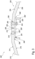
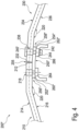
- steel tower sections 200, 200', 200" are shown, which differ in particular with regard to the design of the tab element 250, 250 ⁇ , 250".
- the steel tower sections 200, 200 ⁇ , 200" have a first steel tower ring segment 210 and a second steel tower ring segment 230.
- the first steel tower ring segment 210 is arranged with its first vertical joint side 212 on the second vertical joint side 232 of the second steel tower ring segment 230 at a joint 205.
- the first steel tower ring segment 210 and the second steel tower ring segment 230 each have a partially annular cross-section, wherein a surface normal of this cross-section is aligned essentially parallel to the segment height, here orthogonal to the plane of the drawing, wherein the partially annular cross-section is formed by several straight sections, wherein the straight sections enclose a bending angle 220.
- the first steel tower ring segment 210 has an outer peripheral surface 214 and an inner peripheral surface 216.
- the second steel tower ring segment 230 has an outer peripheral surface 234 and an inner peripheral surface 236.
- the bending angle 220 between two straight sections of the first steel tower ring segment 210 is also shown.
- the bending angle 220 is preferably 175°.
- the straight sections of the steel tower ring segments that border the vertical joint sides 212, 232 enclose the segment angle, which is preferably also 175°.
- the first steel tower ring segment 210 has fastening openings 218 in a section adjacent to the first vertical joint side 212, the direction of passage of which is essentially radial.
- the second steel tower ring segment 230 has a fastening opening 238.
- the tab element 250 has a first tab section 252 which is arranged substantially on the first steel tower ring segment 210.
- the tab element 250 also has a second tab section 254 which is arranged substantially on the second steel tower ring segment 230.
- the dashed line between the first tab section and the second tab section 252, 254 is shown merely to identify these two sections.
- the tab element 250 shown is designed as an integral component.
- fastening openings 253 are arranged on the first tab section 252 and fastening openings 255 are arranged on the second tab section 254, which are designed to correspond to the fastening openings 218, 238 of the steel tower ring segments 210, 230.
- the tab element 250 is connected to the first steel tower ring segment 210 and the second steel tower ring segment 230 by means of a screw connection, which is shown as an example for the connection of the tab element 250 to the second steel tower ring segment 230.
- a screw 240 is guided from the outer peripheral surface 234 through the fastening opening 238 of the second steel tower ring segment 230 and the fastening opening 255 of the tab element 250 and secured by means of a washer 242 and a nut 244.
- the tab element 250 extends from a first vertical end 256 to a second vertical end 258.
- a first Connection element 260 and a second connection element 262 are arranged on the second vertical end 258.
- the connection elements 260, 262 protrude from the tab element 250 and each enclose a connection angle with the tab element. In the present case, this connection angle is approximately 90°. Furthermore, the connection elements protrude in a connection direction which is aligned essentially radially.
- the tab element 250 ⁇ shown also extends from a first vertical end 256' to a second vertical end 258 ⁇ , with connection elements 260', 262 ⁇ being arranged at the vertical ends 256', 258'.
- the connection elements 260', 262 ⁇ are arranged on the tab element 250 ⁇ by means of a welded connection.
- the connection elements 260', 262 ⁇ are thus initially designed as separate components which are arranged on the tab element 250' and connected to it.
- the connection elements 260', 262 ⁇ are welded on, which is shown schematically by means of the weld seam 261.
- the tab element 250" shown also extends from a first vertical end 256" to a second vertical end 258", with connecting elements 260", 262" being arranged at these ends or at sections adjacent to these vertical ends.
- the connecting elements 260", 262" have fastening sections 264, 266 to which the connecting elements 260", 262" are integrally connected.
- the fastening sections 264, 266 are arranged substantially parallel to the surface of the tab element 250" and are bent at a 90° angle to the connecting elements 260", 262".
- the fastening sections 264, 266 further have through-openings which are arranged corresponding to the fastening openings 253, 255 of the tab element 250" and the fastening openings 218, 238 of the first steel tower ring segment 210 and the second steel tower ring segment 230 in order to connect the components to one another with a screw 240'.
- the tab element 250 is made of Figure 2 shown in detail.
- the tab angle 257 between the first tab section 252 and the second tab section 254 can be seen.
- the tab angle 257 is preferably also 5°.
- it is preferred that the segment angle between two adjacently arranged steel tower ring segments 210, 230 and the tab angle 257 are the same size.
- a vertex 259 is formed, which is arranged at the joint 205.
- FIG. 6 shows a schematic, three-dimensional partial view of an exemplary embodiment of a wind turbine steel tower section.
- the steel tower section 300 has a first steel tower ring segment 310, a second steel tower ring segment 320, a third steel tower ring segment 330 and a fourth steel tower ring segment 340.
- the steel tower section extends with a segment extension from a lower horizontal joint side 370 to an upper horizontal joint side 371.
- the steel tower ring segments 310, 320, 330, 340 are each connected to one another by means of a tab element 350.
- Figure 7 shows a schematic, three-dimensional partial view of another exemplary embodiment of a wind turbine steel tower section 400, wherein the connection elements are arranged in a section of the tab element 450 that is not shown.
- the first steel tower ring segment 410 and the second steel tower ring segment 420 are arranged on one another at a vertical joint 405 and are connected to one another by means of the tab element 450.
- the lower horizontal joint side of the first steel tower ring segment 410 is formed by means of a first vertical flange 412 and the lower horizontal joint side of the second steel tower ring segment 420 is formed by a second vertical flange 422.
- the lower horizontal end 451 of the tab element 450 is arranged at a distance from the lower horizontal abutment sides of the steel tower ring segments 410, 420.
- a gap between the first steel tower ring segment 410 and the second steel tower ring segment 420 and between the first vertical flange 412 and the second vertical flange 422 is preferably sealed.
- an elastic, in particular a flexible, seal is attached to the two steel tower ring segments 410, 420 in the vertical direction below the tab element 450.
- This seal can be considered an extension of the tab element 450.
- This seal preferably extends from the tab element 450 up to and including the vertical flanges 412, 422.
- the seal is advantageously arranged such that it covers the gap.
- the seal can be designed as a rubber seal, with a thickness of 3 to 4 mm being particularly preferred. It is also preferred that the seal is glued in the section explained above, in particular glued on one side.
- FIG 8 shows a schematic, three-dimensional view of an exemplary embodiment of a wind turbine tower.
- the tower 500 has a first wind turbine steel tower section 502 with a total of eight horizontally adjacent steel tower ring segments, in particular with a first steel tower ring segment 510, a second steel tower ring segment 520 and a third steel tower ring segment 530.
- the first steel tower ring segment 510 is arranged at a vertical joint 512 on the second steel tower ring segment 520.
- a tab element (not shown) is arranged on the inner peripheral surface of the first and second steel tower ring segments 510, 520, which is connected to the steel tower ring segments 510, 520 by means of screws, of which only the screw heads are visible here.
- the second steel tower ring segment 520 and the third steel tower ring segment 530 are arranged on one another at a further vertical joint 522 and are connected to the inner peripheral surface of the tower 500 by means of a tab element (not shown).
- a second wind turbine steel tower section 504 is arranged, which also has eight horizontally adjacent steel tower ring segments, in particular a fourth steel tower ring segment 560, a fifth steel tower ring segment 570 and a sixth steel tower ring segment 580.
- the fourth steel tower ring segment 560 and the fifth steel tower ring segment 570 are connected to one another with a link element 514.
- the fifth steel tower ring segment 570 and the sixth steel tower ring segment 580 are connected to one another with a link element 524.
- the connection elements are not shown in this schematic drawing.
- the vertically adjacent wind turbine steel tower sections 502, 504 each have a horizontal joint side with which the wind turbine steel tower sections 502, 504 abut one another at a horizontal joint 505.
- eight horizontal link elements for example the horizontal link element 590, are arranged on the horizontal joint and connected to the first wind turbine steel tower section 502 and the second wind turbine steel tower section 504.
- the horizontal link element 590 can extend in the circumferential direction in a ring shape or partially in a ring shape. In particular, it is preferred that the horizontal link element 590 extends in the circumferential direction between two link elements 514, 524. Furthermore, a total of eight horizontal link elements can be arranged between two of the eight link elements.
- FIG 9 shows a schematic, two-dimensional partial view of an exemplary embodiment of another wind turbine tower.
- the tower 900 comprises an upper tower section 902 facing a tower top of the tower 900, and a lower tower section 904 which faces away from the spire of the tower 900.
- the upper tower section 902 and the lower tower section 904 abut one another at a horizontal joint 905 and are connected to one another in the region of the horizontal joint 905.
- the upper tower section 902 is designed in particular as a wind turbine tower section with a first and a second shell steel tower ring segment.
- the first and second shell steel tower ring elements are referred to below as first and second steel tower ring elements.
- the first steel tower ring segment 910 has a first vertical joint side and the second steel tower ring segment 920 has a second vertical joint side.
- the first steel tower ring segment 910 and the second steel tower ring segment 920 are arranged horizontally adjacent to one another.
- the first steel tower ring segment 910 and the second steel tower ring segment 920 abut one another with their vertical joint sides at an upper vertical joint 915.
- a first vertical flange 912 is arranged on the first vertical joint side of the first steel tower ring segment 910.
- a second vertical flange 922 is arranged on the second vertical joint side of the second steel tower ring segment 920.
- the vertical flanges 912, 922 each form an angle with the wall-forming sections of the steel tower ring segments 910, 920.
- Horizontally aligned through-openings are arranged on the vertical flanges 912, 922.
- the through-openings are arranged and designed in particular such that the vertical flanges 912, 922 can be connected to one another by means of fastening elements.
- a first connection element 914 and a second connection element 916 are formed on the first vertical flange 912 and protrude from the first vertical flange 912.
- the connection elements 914, 916 and all other connection elements described below are arranged and designed in particular for the arrangement of functional elements.
- Two connection elements 924, 926 are also formed on the second vertical flange 922 and protrude from the second vertical flange 922.
- the lower tower section 904 comprises a third steel tower ring segment 930 and a fourth steel tower ring segment 940.
- the third steel tower ring segment 930 and the fourth steel tower ring segment 940 abut each other at a lower vertical joint 925 with their vertical joint sides.
- a strap element 906 is arranged on the lower vertical joint 925, which is connected to the third steel tower ring segment 930 and the fourth steel tower ring segment 940.
- the connection is in particular with Fastening elements 932, 942 are implemented, wherein the vertical spacing of the fastening elements in a central section of the tab element 906 is greater than in the two end sections of the tab element 906. In the end sections of the tab element 906, the vertical spacing of the fastening elements is instead chosen to be as small as possible.
- the third steel tower ring segment 930 and the fourth steel tower ring segment 940 are thus connected to one another and held together at the lower vertical joint 925 by the tab element 906.
- the lower tower section 904 also has connection elements 934, 944, wherein the tab element 906 has the connection elements 934, 944.
- the connection elements 934, 944 project from the tab element 906.
- the tab element 250, 250', 250", 350, 450, 514, 524 with a cantilevered connection element 260, 260', 260", 262, 262', 262" has the particular advantage of a particularly cost-effective connection of two steel tower ring segments 210, 230, 310, 320, 410, 420, 510, 520, 530, wherein, in addition, functional elements can be arranged particularly advantageously in the interior of the tower 102, 500 but also on the outside of the tower 102, 500 without having to interfere with the supporting structure, in particular the casing elements of the steel tower ring segments 210, 230, 310, 320, 410, 420, 510, 520, 530, must be welded.
- the steel tower ring segments 210, 230, 310, 320, 410, 420, 510, 520, 530 particularly easy to connect to one another on a construction site, since they have no or reduced distortion.
- the tower 102, 500 is in a predetermined stress state, without hardly predictable stress states being present due to welding.
Landscapes
- Engineering & Computer Science (AREA)
- Chemical & Material Sciences (AREA)
- Life Sciences & Earth Sciences (AREA)
- Architecture (AREA)
- Mechanical Engineering (AREA)
- Combustion & Propulsion (AREA)
- Sustainable Energy (AREA)
- General Engineering & Computer Science (AREA)
- Sustainable Development (AREA)
- Materials Engineering (AREA)
- Wood Science & Technology (AREA)
- Civil Engineering (AREA)
- Structural Engineering (AREA)
- Wind Motors (AREA)
Claims (16)
- Section de tour en acier d'éolienne (200, 200', 200'', 300, 400) pour une tour d'éolienne (102, 500) comprenant- un premier segment annulaire de tour en acier d'éolienne (210, 310, 410, 510) avec une première face de butée verticale (212),- un second segment annulaire de tour en acier d'éolienne (230, 320, 420, 520) avec une seconde face de butée verticale (232),- un élément de languette (250, 250', 250'', 350, 450, 514, 524) qui est agencé au niveau d'une butée (205, 405, 512, 522) et est relié au premier segment annulaire de tour en acier d'éolienne (210, 310, 410, 510) et au second segment annulaire de tour en acier d'éolienne (230, 320, 420, 520),- dans laquelle le premier segment annulaire de tour en acier d'éolienne (210, 310, 410, 510) avec la première face de butée verticale (212) et le second segment annulaire de tour en acier d'éolienne (230, 320, 420, 520) avec la seconde face de butée verticale (232) sont agencés sur la butée (205, 405, 512, 522) l'un sur l'autre, et- l'élément de languette (250, 250', 250'', 350, 450, 514, 524) présente un élément de raccordement (260, 260', 260", 262, 262', 262'') faisant saillie de l'élément de languette (250, 250', 250", 350, 450, 514, 524) pour l'agencement d'éléments fonctionnels, caractérisée en ce que- l'élément de raccordement (260, 260', 260", 262, 262', 262'') est relié à l'élément de languette (250, 250', 250", 350, 450, 514, 524) par matière ou au moyen d'au moins un élément de fixation (240').
- Section de tour en acier d'éolienne (200, 200', 200'', 300, 400) selon la revendication précédente, dans laquelle- l'élément de languette (250, 250', 250", 350, 450, 514, 524) et l'élément de raccordement (260, 260', 260", 262, 262', 262") forment un angle de raccordement (220), et/ou- l'élément de raccordement (260, 260', 260", 262, 262', 262'') fait saillie dans un sens de saillie et le sens de saillie est orienté sensiblement radialement.
- Section de tour en acier d'éolienne (200, 200', 200'', 300, 400) selon au moins l'une quelconque des revendications précédentes, dans laquelle- l'élément de raccordement (260, 260', 260", 262, 262', 262'') est réalisé d'un seul tenant avec l'élément de languette (250, 250', 250", 350, 450, 514, 524), et/ou- l'élément de raccordement (260, 260', 260", 262, 262', 262'') est relié à l'élément de languette (250, 250', 250", 350, 450, 514, 524).
- Section de tour en acier d'éolienne (200, 200', 200", 300, 400) selon au moins l'une quelconque des revendications précédentes, dans laquelle- l'élément de raccordement (260, 260', 260'', 262, 262', 262") est relié à l'élément de languette (250, 250', 250", 350, 450, 514, 524) par soudage.
- Section de tour en acier d'éolienne (200, 200', 200'', 300, 400) selon au moins l'une quelconque des revendications précédentes, dans laquelle- l'élément de raccordement (260, 260', 260'', 262, 262', 262'') présente une section de fixation (264, 266), dans laquelle- l'élément de raccordement (260, 260', 260'', 262, 262', 262'') est relié à la section de fixation (264, 266), et/ou- l'élément de raccordement (260'', 262'') est réalisé d'un seul tenant avec la section de fixation, et est de préférence réalisé comme élément angulaire.
- Section de tour en acier d'éolienne (200, 200', 200'', 300, 400) selon au moins l'une quelconque des revendications précédentes, dans laquelle- l'élément de languette (250, 250', 250'', 350, 450, 514, 524) s'étend d'une première extrémité verticale (256, 256', 256'') à une seconde extrémité verticale (258, 258', 258'') et d'une extrémité horizontale supérieure à une extrémité horizontale inférieure (451), et/ou- un premier élément de raccordement (260, 260', 260'') est agencé au niveau de la première extrémité verticale (256, 256', 256'') et un second élément de raccordement (262, 262', 262") est agencé au niveau de la seconde extrémité verticale (258, 258', 258''), et/ou- le premier élément de raccordement (260, 260', 260") et le second élément de raccordement (262, 262', 262'') présentent de préférence le même espacement à une première face de butée horizontale (371) et/ou une première face de butée horizontale inférieure (370) du premier segment annulaire de tour en acier d'éolienne (210, 310, 410, 510) et/ou à une seconde face de butée horizontale supérieure et/ou une seconde face de butée horizontale inférieure du second segment annulaire de tour en acier d'éolienne (230, 320, 420, 520) .
- Section de tour en acier d'éolienne (200, 200', 200'', 300, 400) selon au moins l'une quelconque des revendications précédentes, dans laquelle l'élément de languette (250, 250', 250'', 350, 450, 514, 524) est agencé sur une surface périphérique intérieure (216, 236) et/ou une surface périphérique extérieure (214, 234) du premier segment annulaire de tour en acier d'éolienne (210, 310, 410, 510) et du second segment annulaire de tour en acier d'éolienne (230, 320, 420, 520) .
- Section de tour en acier d'éolienne (200, 200', 200'', 300, 400) selon au moins l'une quelconque des revendications précédentes, dans laquelle- l'élément de languette (250, 250', 250'', 350, 450, 514, 524) présente une première section de languette (252, 252', 252") qui est agencée sensiblement au niveau du premier segment annulaire de tour en acier d'éolienne (210, 310, 410, 510) et/ou une seconde section de languette (254, 254', 254") qui est agencée sensiblement au niveau du second segment annulaire de tour en acier d'éolienne (230, 320, 420, 520),- dans laquelle la première section de languette (252, 252', 252'') et la seconde section de languette (254, 254', 254'') forment de préférence un angle de languette (257).
- Section de tour en acier d'éolienne (200, 200', 200'', 300, 400) selon au moins l'une quelconque des revendications précédentes, dans laquelle- l'élément de languette (250, 250', 250", 350, 450, 514, 524) est agencé avec son sens d'étendue principale sensiblement parallèlement à une hauteur de segment et l'élément de languette (250, 250', 250", 350, 450, 514, 524) présente dans son sens d'étendue principale une étendue de languette de plus de 20 %, de plus de 30 %, de plus de 40 %, de plus de 50 %, de plus de 60 %, de plus de 70 %, de plus de 80 %, de plus de 90 % de l'étendue de segment en direction de la hauteur de segment.
- Section de tour en acier d'éolienne (200, 200', 200'', 300, 400) selon au moins l'une quelconque des revendications précédentes, dans laquelle- la première section de languette (252, 252', 252'') est agencée au niveau d'une première section d'extrémité du premier segment annulaire de tour en acier d'éolienne (210, 310, 410, 510), dans laquelle la première section d'extrémité est contiguë à la première face de butée verticale (212), et/ou- la seconde section de languette (254, 254', 254") est agencée au niveau d'une seconde section d'extrémité du second segment annulaire de tour en acier d'éolienne (230, 320, 420, 520), dans laquelle la seconde section d'extrémité est contiguë à la seconde face de butée verticale (232), et- la première section d'extrémité et la seconde section d'extrémité forment de préférence un angle de segment.
- Section de tour en acier d'éolienne (200, 200', 200'', 300, 400) selon au moins l'une quelconque des revendications précédentes, dans laquelle- l'angle de segment et l'angle de languette (257) sont sensiblement de même taille.
- Section de tour en acier d'éolienne (200, 200', 200'', 300, 400) selon au moins l'une quelconque des revendications précédentes, dans laquelle- le premier segment annulaire de tour en acier d'éolienne (210, 310, 410, 510) et/ou le second segment annulaire de tour en acier d'éolienne (230, 320, 420, 520) et/ou l'élément de languette (250, 250', 250'', 350, 450, 514, 524) présentent des ouvertures de fixation (218, 238, 253, 255) qui sont agencées et réalisées afin de recevoir des éléments de fixation (240).
- Section de tour en acier d'éolienne (200, 200', 200", 300, 400) selon au moins l'une quelconque des revendications précédentes, dans laquelle- l'espacement des ouvertures de fixation (253, 255) est plus faible dans une section d'extrémité de languette supérieure qui est tournée vers l'extrémité horizontale supérieure, et/ou dans une section d'extrémité de languette inférieure qui est tournée vers l'extrémité horizontale inférieure, que l'espacement des ouvertures de fixation (253, 255) dans une section médiane de languette qui est agencée entre la section d'extrémité de languette supérieure et la section d'extrémité de languette inférieure.
- Tour d'éolienne (102, 500) comprenant deux ou plusieurs sections de tour en acier d'éolienne (200, 200', 200", 300, 400) agencées les unes au-dessus des autres selon au moins l'une quelconque des revendications précédentes.
- Eolienne comprenant une tour d'éolienne (102, 500) selon la revendication précédente.
- Procédé de fabrication d'une section de tour en acier d'éolienne (200, 200', 200'', 300, 400) selon au moins l'une quelconque des revendications 1 à 13, caractérisé par- la fourniture d'un premier segment annulaire de tour en acier d'éolienne (210, 310, 410, 510) avec une première face de butée verticale (212), d'un second segment annulaire de tour en acier d'éolienne (230, 320, 420, 520) avec une seconde face de butée verticale (232) et d'un élément de languette (250, 250', 250'', 350, 450, 514, 524) ;- l'agencement du premier segment annulaire de tour en acier d'éolienne (210, 310, 410, 510) et du second segment annulaire de tour en acier d'éolienne (230, 320, 420, 520) au niveau d'une butée (205, 405, 512, 522) avec la première face de butée verticale (212) et la seconde face de butée verticale (232) ;- l'agencement de l'élément de languette (250, 250', 250", 350, 450, 514, 524) au niveau de la butée (205, 405, 512, 522) ;- la liaison de l'élément de languette (250, 250', 250", 350, 450, 514, 524) avec le premier segment annulaire de tour en acier d'éolienne (210, 310, 410, 510) et le second segment annulaire de tour en acier d'éolienne (230, 320, 420, 520).
Applications Claiming Priority (2)
| Application Number | Priority Date | Filing Date | Title |
|---|---|---|---|
| DE102017116872.9A DE102017116872A1 (de) | 2017-07-26 | 2017-07-26 | Windenergieanlagen-Stahlturmabschnitt für einen Windenergieanlagen-Turm und Verfahren zur Herstellung |
| PCT/EP2018/069537 WO2019020464A1 (fr) | 2017-07-26 | 2018-07-18 | Partie de tour en acier pour éoliennes, pour une tour d'éolienne et procédé pour la produire |
Publications (3)
| Publication Number | Publication Date |
|---|---|
| EP3658771A1 EP3658771A1 (fr) | 2020-06-03 |
| EP3658771B1 true EP3658771B1 (fr) | 2024-09-04 |
| EP3658771C0 EP3658771C0 (fr) | 2024-09-04 |
Family
ID=62981212
Family Applications (1)
| Application Number | Title | Priority Date | Filing Date |
|---|---|---|---|
| EP18743466.7A Active EP3658771B1 (fr) | 2017-07-26 | 2018-07-18 | Partie de tour en acier pour éoliennes, pour une tour d'éolienne et procédé pour la produire |
Country Status (10)
| Country | Link |
|---|---|
| US (1) | US20210148335A1 (fr) |
| EP (1) | EP3658771B1 (fr) |
| JP (1) | JP2020528512A (fr) |
| KR (1) | KR20200033296A (fr) |
| CN (1) | CN112204251A (fr) |
| BR (1) | BR112020001490A2 (fr) |
| CA (1) | CA3070257A1 (fr) |
| DE (1) | DE102017116872A1 (fr) |
| RU (1) | RU2741354C1 (fr) |
| WO (1) | WO2019020464A1 (fr) |
Families Citing this family (4)
| Publication number | Priority date | Publication date | Assignee | Title |
|---|---|---|---|---|
| DE102019104350A1 (de) * | 2019-02-20 | 2020-08-20 | Wobben Properties Gmbh | Stahlturmringsegment für einen Windenergieanlagen-Turmabschnitt und Verfahren |
| CN118251546A (zh) * | 2020-10-24 | 2024-06-25 | A·欧库洛古拉瑞 | 模块化风塔架 |
| KR102645328B1 (ko) * | 2022-02-09 | 2024-03-11 | 한국전력공사 | 관형지지물 및 이의 연결방법 |
| EP4446580A1 (fr) * | 2023-04-13 | 2024-10-16 | Siemens Gamesa Renewable Energy Innovation & Technology S.L. | Procédé de fabrication d'une tour tubulaire segmentée, tour tubulaire segmentée et éolienne |
Citations (1)
| Publication number | Priority date | Publication date | Assignee | Title |
|---|---|---|---|---|
| EP2006471A1 (fr) * | 2007-06-20 | 2008-12-24 | Siemens Aktiengesellschaft | Tour d'éolienne et son procédé de construction |
Family Cites Families (8)
| Publication number | Priority date | Publication date | Assignee | Title |
|---|---|---|---|---|
| HUP0201136A2 (hu) * | 2002-04-03 | 2004-04-28 | Meir Silber | Toronyszerkezet |
| DE20321855U1 (de) | 2003-03-19 | 2011-06-09 | Vestas Wind System A/S | Stahlturm für eine Windkraftanlage |
| JP4708365B2 (ja) * | 2004-02-04 | 2011-06-22 | タタ、スティール、アイモイデン、ベスローテン、フェンノートシャップ | 風力タービン用タワー、風力タービン用タワーに使用する予備製作された金属壁部品および風力タービン用タワーの構築方法 |
| DE102005012497A1 (de) | 2005-03-16 | 2006-09-21 | Aloys Wobben | Arbeitsbühne |
| US20110018013A1 (en) * | 2009-07-21 | 2011-01-27 | Koninklijke Philips Electronics N.V. | Thin-film flip-chip series connected leds |
| WO2011110235A2 (fr) * | 2010-03-12 | 2011-09-15 | Siemens Aktiengesellschaft | Partie de paroi de tour d'éolienne |
| US8316615B2 (en) * | 2011-01-19 | 2012-11-27 | General Electric Company | Modular tower and methods of assembling same |
| DE102011077428A1 (de) * | 2011-06-10 | 2012-12-13 | Aloys Wobben | Windenergieanlagen-Turm |
-
2017
- 2017-07-26 DE DE102017116872.9A patent/DE102017116872A1/de not_active Withdrawn
-
2018
- 2018-07-18 JP JP2020502583A patent/JP2020528512A/ja active Pending
- 2018-07-18 EP EP18743466.7A patent/EP3658771B1/fr active Active
- 2018-07-18 US US16/633,919 patent/US20210148335A1/en not_active Abandoned
- 2018-07-18 WO PCT/EP2018/069537 patent/WO2019020464A1/fr not_active Ceased
- 2018-07-18 KR KR1020207005037A patent/KR20200033296A/ko not_active Ceased
- 2018-07-18 BR BR112020001490-7A patent/BR112020001490A2/pt not_active Application Discontinuation
- 2018-07-18 CN CN201880050235.8A patent/CN112204251A/zh not_active Withdrawn
- 2018-07-18 RU RU2020108060A patent/RU2741354C1/ru active
- 2018-07-18 CA CA3070257A patent/CA3070257A1/fr not_active Abandoned
Patent Citations (1)
| Publication number | Priority date | Publication date | Assignee | Title |
|---|---|---|---|---|
| EP2006471A1 (fr) * | 2007-06-20 | 2008-12-24 | Siemens Aktiengesellschaft | Tour d'éolienne et son procédé de construction |
Also Published As
| Publication number | Publication date |
|---|---|
| US20210148335A1 (en) | 2021-05-20 |
| WO2019020464A1 (fr) | 2019-01-31 |
| JP2020528512A (ja) | 2020-09-24 |
| RU2741354C1 (ru) | 2021-01-25 |
| EP3658771A1 (fr) | 2020-06-03 |
| CA3070257A1 (fr) | 2019-01-31 |
| CN112204251A (zh) | 2021-01-08 |
| BR112020001490A2 (pt) | 2020-09-08 |
| DE102017116872A1 (de) | 2019-01-31 |
| KR20200033296A (ko) | 2020-03-27 |
| EP3658771C0 (fr) | 2024-09-04 |
Similar Documents
| Publication | Publication Date | Title |
|---|---|---|
| DE102013107059B4 (de) | Verfahren zur Herstellung und zum Errichten eines Rohrturmbauwerks | |
| EP2932095B1 (fr) | Élément de transition destiné à être disposé entre des portions exécutées différemment d'une tour d'éolienne et tour d'éolienne équipée dudit élément de transition | |
| EP3469212B1 (fr) | Rotor pour éolienne, pale de rotor pour éolienne, manchon et procédé de montage d'un rotor | |
| EP2718519B1 (fr) | Tour éolienne | |
| EP3092358B2 (fr) | Éolienne pourvue d'un mât et d'une embase composée de plusieurs segments | |
| EP3658771B1 (fr) | Partie de tour en acier pour éoliennes, pour une tour d'éolienne et procédé pour la produire | |
| EP3701107B1 (fr) | Console annulaire destinée à la contrainte externe d'un segment de tour, système de contrainte externe d'une tour hybride, section de tour d'une tour hybride, tour hybride, éolienne et procédé de montage d'un système de contrainte externe pour une tour hybride | |
| EP3491239B1 (fr) | Élément de raccordement permettant de raccorder des sections de tour, section de tour, tour, éolienne ainsi que procédé de fabrication d'une section de tour et de raccordement de sections de tour | |
| EP3927918B1 (fr) | Composant d'éolienne pour une tour d'éolienne, tour d'éolienne, pale de rotor, éolienne et procédé de fabrication d'un composant d'éolienne | |
| EP3477099A1 (fr) | Tour pourvue d'éléments adaptateurs en acier coniques | |
| EP3601791B1 (fr) | Segment bride pour un segment annulaire de tour en acier pour éolienne et procédé associé | |
| DE102017120487A1 (de) | Turm einer Windenergieanlage und Verfahren zum Herstellen eines Sektionssegments für einen solchen Turm | |
| WO2009024356A2 (fr) | Structure de mât pour tours en treillis d'éoliennes | |
| DE102016109818A1 (de) | Steigvorrichtung zur Ausführung einer Bewegung relativ zu einem Turm und Verfahren zur Herstellung eines Turms | |
| EP3853472B1 (fr) | Segment de tour d'éolienne pour tour d'éolienne et procédé | |
| DE102016119352A1 (de) | Transportanker | |
| DE102017120488A1 (de) | Turm einer Windenergieanlage und Längsversteifung für einen Turm einer Windenergieanlage | |
| EP3658770B1 (fr) | Segment annulaire de tour en acier pour éoliennes et procédé | |
| DE102006004640A1 (de) | Turm einer Windkraftanlage | |
| EP3956561B1 (fr) | Section de tour et procédé pour la construction d'une tour | |
| EP1873331A2 (fr) | Pylône de ligne électrique aérienne en béton centrifugé | |
| EP3927966B1 (fr) | Segment annulaire de tour en acier pour une partie de tour d'éolienne et procédé | |
| EP3483428A1 (fr) | Moyens d'augmentation de la rigidité flexionnelle des composants porteurs d'une éolienne |
Legal Events
| Date | Code | Title | Description |
|---|---|---|---|
| STAA | Information on the status of an ep patent application or granted ep patent |
Free format text: STATUS: UNKNOWN |
|
| STAA | Information on the status of an ep patent application or granted ep patent |
Free format text: STATUS: THE INTERNATIONAL PUBLICATION HAS BEEN MADE |
|
| PUAI | Public reference made under article 153(3) epc to a published international application that has entered the european phase |
Free format text: ORIGINAL CODE: 0009012 |
|
| STAA | Information on the status of an ep patent application or granted ep patent |
Free format text: STATUS: REQUEST FOR EXAMINATION WAS MADE |
|
| 17P | Request for examination filed |
Effective date: 20200226 |
|
| AK | Designated contracting states |
Kind code of ref document: A1 Designated state(s): AL AT BE BG CH CY CZ DE DK EE ES FI FR GB GR HR HU IE IS IT LI LT LU LV MC MK MT NL NO PL PT RO RS SE SI SK SM TR |
|
| AX | Request for extension of the european patent |
Extension state: BA ME |
|
| DAV | Request for validation of the european patent (deleted) | ||
| DAX | Request for extension of the european patent (deleted) | ||
| STAA | Information on the status of an ep patent application or granted ep patent |
Free format text: STATUS: EXAMINATION IS IN PROGRESS |
|
| 17Q | First examination report despatched |
Effective date: 20220405 |
|
| GRAP | Despatch of communication of intention to grant a patent |
Free format text: ORIGINAL CODE: EPIDOSNIGR1 |
|
| STAA | Information on the status of an ep patent application or granted ep patent |
Free format text: STATUS: GRANT OF PATENT IS INTENDED |
|
| INTG | Intention to grant announced |
Effective date: 20240409 |
|
| GRAS | Grant fee paid |
Free format text: ORIGINAL CODE: EPIDOSNIGR3 |
|
| GRAA | (expected) grant |
Free format text: ORIGINAL CODE: 0009210 |
|
| STAA | Information on the status of an ep patent application or granted ep patent |
Free format text: STATUS: THE PATENT HAS BEEN GRANTED |
|
| AK | Designated contracting states |
Kind code of ref document: B1 Designated state(s): AL AT BE BG CH CY CZ DE DK EE ES FI FR GB GR HR HU IE IS IT LI LT LU LV MC MK MT NL NO PL PT RO RS SE SI SK SM TR |
|
| REG | Reference to a national code |
Ref country code: GB Ref legal event code: FG4D Free format text: NOT ENGLISH |
|
| REG | Reference to a national code |
Ref country code: CH Ref legal event code: EP |
|
| REG | Reference to a national code |
Ref country code: IE Ref legal event code: FG4D Free format text: LANGUAGE OF EP DOCUMENT: GERMAN |
|
| REG | Reference to a national code |
Ref country code: DE Ref legal event code: R096 Ref document number: 502018015092 Country of ref document: DE |
|
| U01 | Request for unitary effect filed |
Effective date: 20240904 |
|
| U07 | Unitary effect registered |
Designated state(s): AT BE BG DE DK EE FI FR IT LT LU LV MT NL PT RO SE SI Effective date: 20240920 |
|
| PG25 | Lapsed in a contracting state [announced via postgrant information from national office to epo] |
Ref country code: NO Free format text: LAPSE BECAUSE OF FAILURE TO SUBMIT A TRANSLATION OF THE DESCRIPTION OR TO PAY THE FEE WITHIN THE PRESCRIBED TIME-LIMIT Effective date: 20241204 |
|
| PG25 | Lapsed in a contracting state [announced via postgrant information from national office to epo] |
Ref country code: PL Free format text: LAPSE BECAUSE OF FAILURE TO SUBMIT A TRANSLATION OF THE DESCRIPTION OR TO PAY THE FEE WITHIN THE PRESCRIBED TIME-LIMIT Effective date: 20240904 Ref country code: GR Free format text: LAPSE BECAUSE OF FAILURE TO SUBMIT A TRANSLATION OF THE DESCRIPTION OR TO PAY THE FEE WITHIN THE PRESCRIBED TIME-LIMIT Effective date: 20241205 |
|
| PG25 | Lapsed in a contracting state [announced via postgrant information from national office to epo] |
Ref country code: HR Free format text: LAPSE BECAUSE OF FAILURE TO SUBMIT A TRANSLATION OF THE DESCRIPTION OR TO PAY THE FEE WITHIN THE PRESCRIBED TIME-LIMIT Effective date: 20240904 |
|
| PG25 | Lapsed in a contracting state [announced via postgrant information from national office to epo] |
Ref country code: ES Free format text: LAPSE BECAUSE OF FAILURE TO SUBMIT A TRANSLATION OF THE DESCRIPTION OR TO PAY THE FEE WITHIN THE PRESCRIBED TIME-LIMIT Effective date: 20240904 Ref country code: RS Free format text: LAPSE BECAUSE OF FAILURE TO SUBMIT A TRANSLATION OF THE DESCRIPTION OR TO PAY THE FEE WITHIN THE PRESCRIBED TIME-LIMIT Effective date: 20241204 |
|
| PG25 | Lapsed in a contracting state [announced via postgrant information from national office to epo] |
Ref country code: RS Free format text: LAPSE BECAUSE OF FAILURE TO SUBMIT A TRANSLATION OF THE DESCRIPTION OR TO PAY THE FEE WITHIN THE PRESCRIBED TIME-LIMIT Effective date: 20241204 Ref country code: PL Free format text: LAPSE BECAUSE OF FAILURE TO SUBMIT A TRANSLATION OF THE DESCRIPTION OR TO PAY THE FEE WITHIN THE PRESCRIBED TIME-LIMIT Effective date: 20240904 Ref country code: NO Free format text: LAPSE BECAUSE OF FAILURE TO SUBMIT A TRANSLATION OF THE DESCRIPTION OR TO PAY THE FEE WITHIN THE PRESCRIBED TIME-LIMIT Effective date: 20241204 Ref country code: HR Free format text: LAPSE BECAUSE OF FAILURE TO SUBMIT A TRANSLATION OF THE DESCRIPTION OR TO PAY THE FEE WITHIN THE PRESCRIBED TIME-LIMIT Effective date: 20240904 Ref country code: GR Free format text: LAPSE BECAUSE OF FAILURE TO SUBMIT A TRANSLATION OF THE DESCRIPTION OR TO PAY THE FEE WITHIN THE PRESCRIBED TIME-LIMIT Effective date: 20241205 Ref country code: ES Free format text: LAPSE BECAUSE OF FAILURE TO SUBMIT A TRANSLATION OF THE DESCRIPTION OR TO PAY THE FEE WITHIN THE PRESCRIBED TIME-LIMIT Effective date: 20240904 |
|
| PG25 | Lapsed in a contracting state [announced via postgrant information from national office to epo] |
Ref country code: IS Free format text: LAPSE BECAUSE OF FAILURE TO SUBMIT A TRANSLATION OF THE DESCRIPTION OR TO PAY THE FEE WITHIN THE PRESCRIBED TIME-LIMIT Effective date: 20250104 |
|
| PG25 | Lapsed in a contracting state [announced via postgrant information from national office to epo] |
Ref country code: SM Free format text: LAPSE BECAUSE OF FAILURE TO SUBMIT A TRANSLATION OF THE DESCRIPTION OR TO PAY THE FEE WITHIN THE PRESCRIBED TIME-LIMIT Effective date: 20240904 |
|
| PG25 | Lapsed in a contracting state [announced via postgrant information from national office to epo] |
Ref country code: CZ Free format text: LAPSE BECAUSE OF FAILURE TO SUBMIT A TRANSLATION OF THE DESCRIPTION OR TO PAY THE FEE WITHIN THE PRESCRIBED TIME-LIMIT Effective date: 20240904 |
|
| PG25 | Lapsed in a contracting state [announced via postgrant information from national office to epo] |
Ref country code: SK Free format text: LAPSE BECAUSE OF FAILURE TO SUBMIT A TRANSLATION OF THE DESCRIPTION OR TO PAY THE FEE WITHIN THE PRESCRIBED TIME-LIMIT Effective date: 20240904 |
|
| PLBE | No opposition filed within time limit |
Free format text: ORIGINAL CODE: 0009261 |
|
| STAA | Information on the status of an ep patent application or granted ep patent |
Free format text: STATUS: NO OPPOSITION FILED WITHIN TIME LIMIT |
|
| U20 | Renewal fee for the european patent with unitary effect paid |
Year of fee payment: 8 Effective date: 20250630 |
|
| 26N | No opposition filed |
Effective date: 20250605 |
|
| REG | Reference to a national code |
Ref country code: CH Ref legal event code: H13 Free format text: ST27 STATUS EVENT CODE: U-0-0-H10-H13 (AS PROVIDED BY THE NATIONAL OFFICE) Effective date: 20260224 |
|
| GBPC | Gb: european patent ceased through non-payment of renewal fee |
Effective date: 20250718 |
|
| PG25 | Lapsed in a contracting state [announced via postgrant information from national office to epo] |
Ref country code: GB Free format text: LAPSE BECAUSE OF NON-PAYMENT OF DUE FEES Effective date: 20250718 |
|
| PG25 | Lapsed in a contracting state [announced via postgrant information from national office to epo] |
Ref country code: CH Free format text: LAPSE BECAUSE OF NON-PAYMENT OF DUE FEES Effective date: 20250731 |