EP3658801B1 - Combinaison d'une transmission avec un dispositif pour bloquer la transmission - Google Patents
Combinaison d'une transmission avec un dispositif pour bloquer la transmission Download PDFInfo
- Publication number
- EP3658801B1 EP3658801B1 EP18732686.3A EP18732686A EP3658801B1 EP 3658801 B1 EP3658801 B1 EP 3658801B1 EP 18732686 A EP18732686 A EP 18732686A EP 3658801 B1 EP3658801 B1 EP 3658801B1
- Authority
- EP
- European Patent Office
- Prior art keywords
- shaft
- transmission
- gear
- drive
- locking
- Prior art date
- Legal status (The legal status is an assumption and is not a legal conclusion. Google has not performed a legal analysis and makes no representation as to the accuracy of the status listed.)
- Active
Links
Images





Classifications
-
- F—MECHANICAL ENGINEERING; LIGHTING; HEATING; WEAPONS; BLASTING
- F16—ENGINEERING ELEMENTS AND UNITS; GENERAL MEASURES FOR PRODUCING AND MAINTAINING EFFECTIVE FUNCTIONING OF MACHINES OR INSTALLATIONS; THERMAL INSULATION IN GENERAL
- F16H—GEARING
- F16H63/00—Control outputs from the control unit to change-speed- or reversing-gearings for conveying rotary motion or to other devices than the final output mechanism
- F16H63/02—Final output mechanisms therefor; Actuating means for the final output mechanisms
- F16H63/30—Constructional features of the final output mechanisms
- F16H63/34—Locking or disabling mechanisms
- F16H63/3416—Parking lock mechanisms or brakes in the transmission
-
- B—PERFORMING OPERATIONS; TRANSPORTING
- B60—VEHICLES IN GENERAL
- B60K—ARRANGEMENT OR MOUNTING OF PROPULSION UNITS OR OF TRANSMISSIONS IN VEHICLES; ARRANGEMENT OR MOUNTING OF PLURAL DIVERSE PRIME-MOVERS IN VEHICLES; AUXILIARY DRIVES FOR VEHICLES; INSTRUMENTATION OR DASHBOARDS FOR VEHICLES; ARRANGEMENTS IN CONNECTION WITH COOLING, AIR INTAKE, GAS EXHAUST OR FUEL SUPPLY OF PROPULSION UNITS IN VEHICLES
- B60K1/00—Arrangement or mounting of electrical propulsion units
-
- F—MECHANICAL ENGINEERING; LIGHTING; HEATING; WEAPONS; BLASTING
- F16—ENGINEERING ELEMENTS AND UNITS; GENERAL MEASURES FOR PRODUCING AND MAINTAINING EFFECTIVE FUNCTIONING OF MACHINES OR INSTALLATIONS; THERMAL INSULATION IN GENERAL
- F16H—GEARING
- F16H2200/00—Transmissions for multiple ratios
- F16H2200/0021—Transmissions for multiple ratios specially adapted for electric vehicles
Definitions
- the present invention relates to a combination of a transmission and a device for blocking the transmission, for example for a vehicle transmission or a transmission for a door drive.
- devices for locking the transmission are used as parking locks to prevent parked vehicles from rolling away unintentionally.
- locking gears with tooth gaps are integrated into the drive train in a rotationally fixed manner. These locking gears block or release the rotation of the drive by means of actuatable pawls that positively engage the tooth gaps.
- These devices for locking the transmission, used as parking locks are engaged when the selector lever of the automatic transmission is moved to position P. This is necessary, for example, to release the vehicle key in the ignition lock for removal when the engine is not running.
- a parking lock arrangement which blocks the transmission by means of a parking lock gear arranged in a rotationally fixed manner and coaxially to the drive shaft.
- this device results in large torque shocks being exerted on the rotor of the electric drive motor when the parking lock is engaged due to the sudden braking of the drive shaft. These torque shocks exceed the torque shocks that occur during normal operation of the electric drive motor and can lead to damage to the electric drive motor and the transmission.
- the rotor of the electric drive motor In electrically powered vehicles, the rotor of the electric drive motor is constantly engaged with the transmission and is therefore not decoupled from the transmission when the parking lock is engaged.
- the DE 10 2015 214 339 A1 discloses a drive arrangement with an electric motor arranged in a housing and a transmission arranged in the housing.
- the transmission comprises an input stage connected to a rotor shaft of the electric motor, a load stage driven by the input stage, and a differential driven by the load stage.
- the input stage is implemented as a planetary gear, with a sun gear fixed to the rotor shaft, which is implemented as a hollow shaft, a planetary gear set mounted on a web stationary with respect to the housing, and a ring gear rotatably mounted on the web.
- the ring gear is mounted on the web via a connecting shaft via a main radial bearing, and a parking lock gear is connected in a rotationally fixed manner to the connecting shaft.
- the main radial bearing is arranged in a plane with the tooth crowns of the parking lock gear to prevent tilting of the parking lock gear.
- the US 2012/0216638 A1 Describes a drive system with an electric motor and a transmission that features a parking lock gear.
- the parking lock gear is non-rotatably connected to an output shaft.
- the DE 10 2006 046 712 A1 discloses a transmission with a parking lock gear, wherein an external toothing of the parking lock gear is formed on a disk carrier disc which is connected in a rotationally fixed manner to a drive shaft of the transmission.
- the DE 10 2009 021 300 A1 discloses a parking lock, wherein bolts can be inserted axially into holes of a spur gear by a mechanism.
- DE 10 2007 062 349 A1 A transmission with a device for blocking the transmission is known, which comprises a locking wheel with flexible spokes.
- the device according to the invention with the characterizing part of claim 1 has the advantage that a combination of a gear and a device for blocking the gear is created, which avoids torque shocks and is robust, functionally reliable, space-saving and cost-effective.
- the invention relates to a combination of a transmission and a device for blocking the transmission, comprising at least one shaft and at least one locking gear arranged coaxially on the shaft, wherein the locking gear arranged coaxially on the shaft is connected to the shaft of the transmission to be blocked by a torsionally flexible connection.
- the torsionally flexible connection between the locking gear and the shaft is a hollow shaft, wherein either the shaft is a drive shaft of the transmission, and the locking gear is arranged coaxially on the drive shaft of the transmission with the torsionally flexible hollow shaft, and the hollow shaft is connected in a rotationally fixed manner to a drive pinion of a first spur gear stage arranged on the drive shaft of the transmission, or the shaft is an intermediate shaft of the transmission, and the locking gear is arranged coaxially on the intermediate shaft of the transmission with the torsionally flexible hollow shaft, and the hollow shaft is connected in a rotationally fixed manner to a spur gear of a first spur gear stage of the transmission arranged on the intermediate shaft of the transmission.
- the torsionally soft connection has the advantage that torque shocks occurring when the gear is locked are elastically cushioned by the torsionally soft connection, thus preventing damage to drive components caused by torque shocks that exceed those experienced during normal operation. This is particularly true for the constantly engaged In electric drives, the smooth connection of the locking wheel prevents damage to the electric drive motor.
- a hollow shaft is advantageously used between the locking gear and a gear shaft.
- the geometric design of the hollow shaft including diameter, length, and wall thickness, as well as the material selection, makes it very easy to determine the required mechanical properties of the hollow shaft.
- a first embodiment of the invention is the connection of the device for locking a gear through the rotationally fixed connection of the hollow shaft to a drive pinion of a first spur gear stage arranged on a drive shaft of the drive.
- the rotationally fixed connection to the drive pinion eliminates the need for an additional shaft-hub connection between the hollow shaft and the drive shaft.
- the parking lock gear with the torsionally flexible hollow shaft is arranged coaxially on an intermediate shaft of the transmission. This arrangement enables the space-saving integration of the parking lock gear into the transmission and is very cost-effective, as any existing shaft with its bearings can be used.
- a particularly advantageous feature of the device for locking a gear is the non-rotatable connection of the hollow shaft to a spur gear located on an intermediate shaft of the drive.
- the spur gear is continuously operatively connected to other spur gears of the gear, so the hollow shaft is also continuously operatively connected to the gear via this spur gear.
- the non-rotatable connection to the spur gear eliminates the need for an additional shaft-hub connection between the hollow shaft and the gear shaft.
- the hollow shaft of the gear locking device is advantageously mounted on the drive shaft in a rotationally flexible manner.
- This bearing designed as a plain bearing or roller bearing, advantageously prevents the locking forces of the locking gear from leading to bending stresses and thus to plastic deformation of the hollow shaft. This eliminates the risk of imbalance due to a deformed hollow shaft.
- the design of this bearing with a clearance fit is advantageous because the drive shaft and hollow shaft rotate at the same speed. Any deflection of the hollow shaft that may occur is supported by the clearance fit, with deflection of the hollow shaft leading to contact between the hollow shaft and the drive shaft.
- the design of the clearance fit between the hollow shaft and drive shaft limits the greatest possible deflection of the hollow shaft in the elastic range.
- the clearance fit allows the hollow shaft to rotate when the gear is locked, since no torque is transmitted. By using a clearance fit as a bearing, the hollow shaft can be easily pushed onto the drive shaft during assembly without any effort.
- the hollow shaft of the gear locking device is advantageously mounted on the intermediate shaft in a rotationally flexible manner.
- This bearing designed as a plain bearing or roller bearing, advantageously prevents the increased locking forces of the locking gear from leading to bending stresses and thus to plastic deformation of the hollow shaft when arranged on an intermediate shaft. This eliminates the possibility of imbalance due to a deformed hollow shaft.
- the design of this bearing as a clearance fit is advantageous, since the intermediate shaft and hollow shaft rotate at the same speed. Any deflection of the hollow shaft that may occur is supported by the clearance fit, whereby a deflection of the hollow shaft leads to the hollow shaft coming into contact with the intermediate shaft.
- the design of the clearance fit between the hollow shaft and intermediate shaft limits the greatest possible deflection of the hollow shaft in the elastic range.
- the clearance fit allows for rotation of the hollow shaft when inserting the The gearbox is blocked because no torque is transmitted.
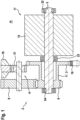
- FIG. 1 shows a schematic representation of a section through a drive unit 14 consisting of an electric motor 17 and a gear 2.
- the electric motor 17 is shown with its rotor 15 and the drive shaft 5.
- the electric motor 17 drives the operatively connected spur gear 8 of a spur gear stage 9 via the drive pinion 6 arranged on its drive shaft 5.
- the Output 21 of spur gear stage 9 drives the operatively connected differential 18.
- the hollow shaft 11, which is arranged coaxially to the drive shaft 5, is non-rotatably connected to the drive pinion 6, via which hollow shaft 11 the locking gear 3 is connected to the drive pinion 6.
- the gear 2 is blocked when necessary via the pawl with locking element 19.
- the drive shaft 5 is supported by the rolling bearings 22, 23, and 24, with at least one of the rolling bearings 22, 23, and 24 being designed as a fixed bearing to absorb the longitudinal forces of the drive shaft 5.
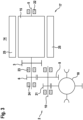
- FIG. 2 shows a schematic sectional drawing through a drive unit 14 of an electric axle drive.
- This drive unit 14 consists of an electric motor 17 and a gearbox 2.
- the electric motor 17 is shown with its stator 25 and its rotor 15 and the drive shaft 5.
- the drive pinion 6 is arranged on the drive shaft 5 with a rotationally fixed connection. A tongue and groove connection, a splined shaft connection or another suitable positive shaft-hub connection can be used for this purpose.
- the drive pinion 6 drives the input spur gear 8 of the intermediate stage 9, which is arranged on an intermediate shaft 10 and operatively connected to the drive pinion 6.
- the input spur gear 8 is rotationally fixedly connected to the intermediate shaft 10 of the intermediate stage 9 via a tongue and groove connection or a splined shaft connection or another suitable positive shaft-hub connection.
- the output spur gear 21 of the intermediate stage 9 is also arranged on the intermediate shaft 10 in a rotationally fixed manner.
- a tongue and groove connection, a splined shaft connection, or another suitable positive shaft-hub connection can be used for this purpose.
- material-to-material connections can also be selected.
- the intermediate shaft 10 with the input spur gear 8 and the output spur gear 21 can be manufactured from a single blank.
- a part consisting of the intermediate shaft 10 with the input spur gear 8 and the output spur gear 21 can be produced by welding two or more blanks.
- the output spur gear 21 drives the operatively connected differential gear 18.
- the hollow shaft 11, which is arranged coaxially to the drive shaft 5, is rotationally fixedly connected to the drive pinion 6.
- the hollow shaft 11 connects the locking gear 3 to the drive pinion 6. is connected in a rotationally flexible manner.
- the gear 2 is blocked when necessary via the pawl with locking element 19.
- the drive shaft 5 is mounted on the roller bearings 22, 23 and 24, with at least one of the roller bearings 22, 23 and 24 being designed as a so-called fixed bearing to absorb the longitudinal forces of the drive shaft 5.
- the bearing point 26 is provided for the rotationally flexible mounting of the hollow shaft 11 and the locking gear 3 on the drive shaft 5.
- This bearing point 26 advantageously prevents the locking forces of the locking gear 3 from leading to inadmissible deformation of the hollow shaft 11 via bending stresses. This rules out an imbalance due to a defectively deformed hollow shaft 11.
- the design of this bearing point 26 as a clearance fit is advantageous because the drive shaft 5 and the hollow shaft 11 rotate at the same speed. Any elastic deflection of the hollow shaft 11 that may occur is supported by the clearance fit, whereby a deflection of the hollow shaft 11 leads to the hollow shaft 11 coming into contact with the drive shaft 5.
- the design of the clearance fit between the hollow shaft 11 and the drive shaft 5 limits the greatest possible deflection of the hollow shaft 11.
- the clearance fit allows rotation of the hollow shaft 11 when the pawl is engaged with the locking element 19 of the gearbox, since no torque is transmitted via the bearing point 26.
- the hollow shaft 11 can be easily pushed onto the drive shaft 5 during assembly without any effort.
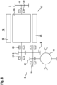
- Figure 3 shows a schematic representation of an arrangement of a locking wheel 3 on the drive shaft 5 in a drive unit of an electrically driven axle 14, adjacent to the rotor 15 on the gearbox side.
- the entire drive unit consists of an electric motor 17 and a gearbox 2.
- the electric motor 17 is shown with its stator 25 and its rotor 15 and the drive shaft 5.
- the drive pinion 6 is arranged on the drive shaft 5 with a rotationally fixed connection.
- the drive shaft is supported by the rolling bearings 22, 23 and 24.
- the gearbox 2 is shown as a two-stage spur gear transmission.
- the drive pinion 6 is operatively connected to the input spur gear 8.
- the output spur gear 21 is arranged on the intermediate shaft 10. This output spur gear 21 is operatively connected to the differential gear 18.
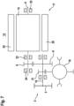
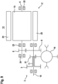
- Figure 4 shows a schematic representation of an arrangement of a locking wheel 3 on the drive shaft 5 of a drive unit of an electrically driven axle 14, adjacent to the rotor 15 on the rotor side.
- a locking wheel 3 with elastic spokes for the torsionally smooth blocking of the gear 2.
- the locking wheel 3, together with the pawl 19 and the locking element can be integrated into the electric motor 17.
- this arrangement is also suitable for use in drives with a separate electric motor 17 and gear 2.
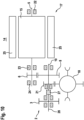
- Figure 5 shows a schematic representation of a transmission-side flying arrangement of a locking wheel 3 on the drive shaft 5 of a drive unit of an electrically driven axle 14.
- a locking wheel 3 with elastic spokes for the torsionally smooth blocking of the gear 2.
- the locking wheel 3 can be integrated into the gear 2 together with the pawl 19 and the locking element.
- This arrangement is suitable not only for use in integrated drive units 14 but also for use in drives with a separate electric motor 17 and gear 2.
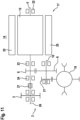
- Figure 6 shows a schematic representation of a rotor-side flying arrangement of a locking wheel 3 on the drive shaft 5 of a drive unit of an electrically driven axle 14.
- a locking wheel 3 with elastic spokes for the torsionally smooth blocking of the gear 2.
- the locking wheel 3 can be attached to the electric motor 17 together with the pawl 19 with the locking element.
- This arrangement is suitable not only for use in integrated drive units 14 but also for use in drives with a separate electric motor 17 and gear 2.
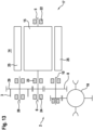
- Figure 7 shows a schematic representation of a floating arrangement of a locking wheel 3 on an intermediate shaft 10 of a drive unit of an electrically driven axle 14.
- a locking wheel 3 with elastic spokes is recommended for the torsionally smooth blocking of the gearbox 2.
- the hub of the locking wheel 3, the input spur gear 8, and the output spur gear 21 are connected in a rotationally fixed manner to the intermediate shaft 10.
- the locking wheel 3 can be attached to the gearbox 2 together with the pawl 19 with the locking element.
- this arrangement is suitable for use in drives with a separate electric motor 17 and gearbox 2.
- Figure 8 shows a schematic representation of an integrated arrangement of a locking wheel 3 on an intermediate shaft 10 of a drive unit of an electrically driven axle 14.
- a locking wheel 3 with elastic spokes is recommended for the torsionally smooth blocking of the transmission 2.
- the hub of the locking wheel 3, the input spur gear 8, and the output spur gear 21 are connected in a rotationally fixed manner to the intermediate shaft 10.
- the locking wheel 3 can be integrated into the transmission 2 together with the pawl 19 and the locking element.
- this arrangement is also suitable for use in drives with a separate electric motor 17 and transmission 2.
- Figure 9 shows a schematic representation of an integrated arrangement of a locking gear 3 with a hollow shaft 11 on an intermediate shaft 10 of a drive unit of an electrically driven axle 14.
- the hollow shaft 11 for the torsionally soft blocking of the transmission 2 is connected in a rotationally fixed manner to the output spur gear 21, which in turn is connected in a rotationally fixed manner to the intermediate shaft 10.
- the input spur gear 8 is also connected in a rotationally fixed manner to the intermediate shaft 10.
- the locking gear 3 can be integrated into the transmission 2 together with the pawl 19 with the locking element.
- This arrangement is suitable not only for use in integrated drive units 14 but also for use in drives with a separate electric motor 17 and transmission 2.
- Figure 10 shows a schematic representation of a non-rotatable arrangement of a locking wheel 3 on its own shaft, which is non-rotatably connected to an intermediate shaft 10 of a transmission 2 of a drive unit of an electrically driven axle 14.
- the non-rotatable coupling 27 connects a stub of the intermediate shaft 10 to a bearing shaft 28 on which the locking wheel 3 is arranged.
- the locking wheel 3 can be attached to the transmission 2 together with the pawl 19 with the locking element.
- the use of a locking wheel 3 with elastic spokes is recommended for the smooth, torsionally locking of the transmission 2.
- FIG 11 shows a schematic representation of a non-rotatable arrangement of a locking wheel 3 on its own shaft, which is non-rotatably connected on the gearbox 2 side to the drive shaft 5 of a drive unit of an electrically driven axle 14.
- the non-rotatable coupling 27 connects a gearbox-side stub of the drive shaft 5 to a bearing shaft 28 on which the locking wheel 3 is arranged.
- the locking wheel 3 can be attached to the gearbox 2 together with the pawl 19 with the locking element.
- the use of a locking wheel 3 with elastic spokes is recommended for the smooth, torsionally locking of the gearbox 2.
- Figure 12 shows a schematic representation of a non-rotatable arrangement of a locking wheel 3 on its own shaft, which is non-rotatably connected on the side of the electric motor 17 to the drive shaft 5 of a drive unit of an electrically driven axle 14.
- the non-rotatable coupling 27 connects a rotor-side stub of the drive shaft 5 to a bearing shaft 28 on which the locking wheel 3 is arranged.
- the locking wheel 3 can be attached to the electric motor 17 together with the pawl 19 with the locking element.
- the use of a locking wheel 3 with elastic spokes is recommended for the smooth, torsion-free blocking of the transmission 2.
- FIG 13 shows a schematic representation of a locking wheel 3 on its own bearing shaft 28, which is connected in a rotationally fixed manner to a locking spur gear 29.
- This locking spur gear 29 is connected to the drive pinion 6 operatively connected.
- the locking gear 3 forms a unit together with the bearing shaft 28 and the pawl with locking element 19 (not shown).
- This unit can be mounted as a separate unit in a gearbox 2.
- the use of a locking gear 3 with elastic spokes is recommended for the smooth torsion blocking of the gearbox 2.
- the hub of the locking gear 3 with elastic spokes is connected in a rotationally fixed manner to the locking spur gear 29, thus ensuring smooth torsion blocking of the gearbox 2.
Landscapes
- Engineering & Computer Science (AREA)
- General Engineering & Computer Science (AREA)
- Mechanical Engineering (AREA)
- Chemical & Material Sciences (AREA)
- Combustion & Propulsion (AREA)
- Transportation (AREA)
- Gear Transmission (AREA)
Claims (3)
- Combinaison d'une transmission (2) et d'un dispositif de blocage de la transmission (2) avec au moins un arbre et au moins une roue de blocage (3) agencée coaxialement sur l'arbre, la roue de blocage (3) agencée coaxialement sur l'arbre étant reliée à l'arbre de la transmission (2) à bloquer par une liaison souple en torsion (4), caractérisée en ce que la liaison souple en torsion (4) entre la roue de blocage (3) et l'arbre est un arbre creux (11), et, soit- l'arbre est un arbre d'entraînement (5) de la transmission (2) et
la roue de blocage (3) est agencée coaxialement sur l'arbre d'entraînement (5) de la transmission (2) avec l'arbre creux (11) souple en torsion et l'arbre creux (11) est relié de manière solidaire en rotation à un pignon d'entraînement (6) d'un premier étage d'engrenage droit (9) agencé sur l'arbre d'entraînement (5) de la transmission (2), soit- l'arbre est un arbre intermédiaire (10) de la transmission (2) et la roue de blocage (2) est agencée avec l'arbre creux (11) de façon souple en torsion coaxialement sur l'arbre intermédiaire (10) de la transmission (2) et l'arbre creux (11) est relié de manière solidaire en rotation à un pignon droit (8) d'un premier étage d'engrenage droit (9) de la transmission (2), agencée sur l'arbre intermédiaire (10) de la transmission (2). - Combinaison selon la revendication 1, caractérisée en ce que l'arbre de la transmission (2) est l'arbre d'entraînement (5) de la transmission (2), et l'arbre creux (11) est monté de manière souple en torsion sur l'arbre d'entraînement (5).
- Combinaison selon la revendication 1, caractérisée en ce que l'arbre de la transmission (2) est l'arbre intermédiaire (10) de la transmission (2), et l'arbre creux (11) est monté de manière souple en torsion sur l'arbre intermédiaire (10).
Applications Claiming Priority (2)
| Application Number | Priority Date | Filing Date | Title |
|---|---|---|---|
| DE102017212804.6A DE102017212804A1 (de) | 2017-07-26 | 2017-07-26 | Einrichtung zur Blockierung eines Getriebes |
| PCT/EP2018/064864 WO2019020252A1 (fr) | 2017-07-26 | 2018-06-06 | Dispositif pour bloquer une transmission |
Publications (2)
| Publication Number | Publication Date |
|---|---|
| EP3658801A1 EP3658801A1 (fr) | 2020-06-03 |
| EP3658801B1 true EP3658801B1 (fr) | 2025-05-14 |
Family
ID=62684753
Family Applications (1)
| Application Number | Title | Priority Date | Filing Date |
|---|---|---|---|
| EP18732686.3A Active EP3658801B1 (fr) | 2017-07-26 | 2018-06-06 | Combinaison d'une transmission avec un dispositif pour bloquer la transmission |
Country Status (4)
| Country | Link |
|---|---|
| EP (1) | EP3658801B1 (fr) |
| CN (1) | CN111094806B (fr) |
| DE (1) | DE102017212804A1 (fr) |
| WO (1) | WO2019020252A1 (fr) |
Families Citing this family (3)
| Publication number | Priority date | Publication date | Assignee | Title |
|---|---|---|---|---|
| US11313464B2 (en) | 2018-04-26 | 2022-04-26 | Gkn Automotive Limited | Parking lock unit and drive arrangement |
| DE102019118828B4 (de) * | 2019-07-11 | 2021-02-04 | Schaeffler Technologies AG & Co. KG | Parksperrenvorrichtung für eine elektrische Antriebsachse und elektrische Antriebsachse mit einer Parksperrenvorrichtung |
| DE102020207340A1 (de) | 2020-06-15 | 2021-12-16 | Robert Bosch Gesellschaft mit beschränkter Haftung | Parksperreneinrichtung für ein Fahrzeug und Verfahren zum Herstellen einer Parksperreneinrichtung für ein Fahrzeug |
Citations (3)
| Publication number | Priority date | Publication date | Assignee | Title |
|---|---|---|---|---|
| DE10029628A1 (de) * | 1999-09-13 | 2001-03-29 | Daimler Chrysler Ag | Drehmomentübertragungseinrichtung eines Kraftfahrzeuges mit einer überlastgeschützten Parksperre |
| US6419068B1 (en) * | 2000-10-24 | 2002-07-16 | Ford Global Technologies, Inc. | Park gear damper for an automatic transmission for an automotive vehicle |
| DE102007062349A1 (de) * | 2007-12-22 | 2009-06-25 | Dr. Ing. H.C. F. Porsche Aktiengesellschaft | Parksperreneinrichtung in einem Getriebe |
Family Cites Families (8)
| Publication number | Priority date | Publication date | Assignee | Title |
|---|---|---|---|---|
| FR2877417B1 (fr) * | 2004-11-02 | 2006-12-22 | Renault Sas | Dispositif d'immobilisation d'un vehicule en position de parking |
| JP2008087606A (ja) * | 2006-09-29 | 2008-04-17 | Honda Motor Co Ltd | 変速機 |
| DE102006046712A1 (de) * | 2006-10-02 | 2008-04-03 | Zf Friedrichshafen Ag | Parksperrenvorrichtung für ein Kraftfahrzeug |
| DE102007055768A1 (de) | 2007-12-12 | 2009-06-18 | Zf Friedrichshafen Ag | Elektrischer Antrieb |
| DE102009021300A1 (de) * | 2009-05-14 | 2010-11-18 | Schaeffler Technologies Gmbh & Co. Kg | Rotationsarretierung für ein um eine Achse drehbares Bauteil |
| US20120216638A1 (en) * | 2009-09-17 | 2012-08-30 | Borgwarner Inc. | Electric vehicle three speed dual clutch transmission |
| DE102012020884A1 (de) * | 2012-10-24 | 2014-04-24 | Audi Ag | Geschwindigkeits-Wechselgetriebe für Kraftfahrzeuge |
| DE102015214339A1 (de) * | 2015-07-29 | 2017-02-02 | Volkswagen Aktiengesellschaft | Antriebsanordnung für ein Kraftfahrzeug |
-
2017
- 2017-07-26 DE DE102017212804.6A patent/DE102017212804A1/de active Pending
-
2018
- 2018-06-06 CN CN201880062369.1A patent/CN111094806B/zh active Active
- 2018-06-06 EP EP18732686.3A patent/EP3658801B1/fr active Active
- 2018-06-06 WO PCT/EP2018/064864 patent/WO2019020252A1/fr not_active Ceased
Patent Citations (3)
| Publication number | Priority date | Publication date | Assignee | Title |
|---|---|---|---|---|
| DE10029628A1 (de) * | 1999-09-13 | 2001-03-29 | Daimler Chrysler Ag | Drehmomentübertragungseinrichtung eines Kraftfahrzeuges mit einer überlastgeschützten Parksperre |
| US6419068B1 (en) * | 2000-10-24 | 2002-07-16 | Ford Global Technologies, Inc. | Park gear damper for an automatic transmission for an automotive vehicle |
| DE102007062349A1 (de) * | 2007-12-22 | 2009-06-25 | Dr. Ing. H.C. F. Porsche Aktiengesellschaft | Parksperreneinrichtung in einem Getriebe |
Also Published As
| Publication number | Publication date |
|---|---|
| CN111094806A (zh) | 2020-05-01 |
| WO2019020252A1 (fr) | 2019-01-31 |
| EP3658801A1 (fr) | 2020-06-03 |
| CN111094806B (zh) | 2022-06-03 |
| DE102017212804A1 (de) | 2019-01-31 |
Similar Documents
| Publication | Publication Date | Title |
|---|---|---|
| WO2020099137A1 (fr) | Dispositif d'entraînement électrique pour un véhicule à moteur, en particulier pour un véhicule automobile | |
| DE102005004291B4 (de) | Getriebeanordnung zur variablen Drehmomentverteilung | |
| DE102012022635B4 (de) | Schaltungsanordnung mit Parksperre und Verfahren zu deren Betätigung | |
| DE102012011686A1 (de) | Übersetzungs- und Ausgleichsgetriebe sowie Motor- und Getriebeeinheit | |
| DE102019125397A1 (de) | Getriebe sowie Kraftfahrzeug mit Getriebe | |
| EP3658801B1 (fr) | Combinaison d'une transmission avec un dispositif pour bloquer la transmission | |
| DE102016210578B4 (de) | Wellenkupplungsanordnung | |
| DE2708999C2 (de) | Wechselgetriebe von Kraftfahrzeugen mit einer Sperrvorrichtung für den Rückwärtsgang | |
| DE102022109235B3 (de) | Abkopplungs- und Parksperreneinheit für ein Getriebe eines Fahrzeugs | |
| EP1589244B1 (fr) | Dispositif d'entraînement avec plateau d'entraînement préchargé axiallement | |
| DE102016124920A1 (de) | Schieberad für eine Schaltgetriebeanordnung | |
| EP4614030A2 (fr) | Module de frein de stationnement | |
| WO2020064044A1 (fr) | Unité de transmission pour une transmission de véhicule à moteur dotée d'une roue droite agencée rotative sur un arbre intermédiaire | |
| DE102019118828B4 (de) | Parksperrenvorrichtung für eine elektrische Antriebsachse und elektrische Antriebsachse mit einer Parksperrenvorrichtung | |
| DE102019205608B4 (de) | Parksperrenrad | |
| DE102017125183B4 (de) | Sperrrad, Parksperreinrichtung und Antriebsanordnung für ein Kraftfahrzeug | |
| DE102019131781A1 (de) | Antriebssystem mit im Planetenradsatz implementierter Synchroeinheit als Parksperre | |
| DE102023118140A1 (de) | Antriebseinheit | |
| DE102022127504A1 (de) | Drehmomentübertragungseinrichtung eines Kraftfahrzeugs | |
| DE102009015455A1 (de) | Getriebe für einen Kraftwagen | |
| DE102010004956A1 (de) | Formschlusskupplungsvorrichtung | |
| DE102020126843A1 (de) | Welle-Nabe-Verbindung | |
| DE102023209862B3 (de) | Kraftfahrzeuggetriebe für ein zumindest teilweise elektrisch angetriebenes Kraftfahrzeug | |
| DE102020110611B3 (de) | Getriebe für ein zumindest teilweise elektrisch betriebenes Fahrzeug | |
| DE102004010420A1 (de) | Feststellbremseinrichtung für Fahrzeuge |
Legal Events
| Date | Code | Title | Description |
|---|---|---|---|
| STAA | Information on the status of an ep patent application or granted ep patent |
Free format text: STATUS: UNKNOWN |
|
| STAA | Information on the status of an ep patent application or granted ep patent |
Free format text: STATUS: THE INTERNATIONAL PUBLICATION HAS BEEN MADE |
|
| PUAI | Public reference made under article 153(3) epc to a published international application that has entered the european phase |
Free format text: ORIGINAL CODE: 0009012 |
|
| STAA | Information on the status of an ep patent application or granted ep patent |
Free format text: STATUS: REQUEST FOR EXAMINATION WAS MADE |
|
| 17P | Request for examination filed |
Effective date: 20200226 |
|
| AK | Designated contracting states |
Kind code of ref document: A1 Designated state(s): AL AT BE BG CH CY CZ DE DK EE ES FI FR GB GR HR HU IE IS IT LI LT LU LV MC MK MT NL NO PL PT RO RS SE SI SK SM TR |
|
| AX | Request for extension of the european patent |
Extension state: BA ME |
|
| DAV | Request for validation of the european patent (deleted) | ||
| DAX | Request for extension of the european patent (deleted) | ||
| STAA | Information on the status of an ep patent application or granted ep patent |
Free format text: STATUS: EXAMINATION IS IN PROGRESS |
|
| 17Q | First examination report despatched |
Effective date: 20210209 |
|
| GRAP | Despatch of communication of intention to grant a patent |
Free format text: ORIGINAL CODE: EPIDOSNIGR1 |
|
| STAA | Information on the status of an ep patent application or granted ep patent |
Free format text: STATUS: GRANT OF PATENT IS INTENDED |
|
| INTG | Intention to grant announced |
Effective date: 20250303 |
|
| GRAS | Grant fee paid |
Free format text: ORIGINAL CODE: EPIDOSNIGR3 |
|
| GRAA | (expected) grant |
Free format text: ORIGINAL CODE: 0009210 |
|
| STAA | Information on the status of an ep patent application or granted ep patent |
Free format text: STATUS: THE PATENT HAS BEEN GRANTED |
|
| AK | Designated contracting states |
Kind code of ref document: B1 Designated state(s): AL AT BE BG CH CY CZ DE DK EE ES FI FR GB GR HR HU IE IS IT LI LT LU LV MC MK MT NL NO PL PT RO RS SE SI SK SM TR |
|
| REG | Reference to a national code |
Ref country code: GB Ref legal event code: FG4D Free format text: NOT ENGLISH |
|
| REG | Reference to a national code |
Ref country code: CH Ref legal event code: EP |
|
| REG | Reference to a national code |
Ref country code: DE Ref legal event code: R096 Ref document number: 502018015819 Country of ref document: DE |
|
| REG | Reference to a national code |
Ref country code: IE Ref legal event code: FG4D Free format text: LANGUAGE OF EP DOCUMENT: GERMAN |
|
| REG | Reference to a national code |
Ref country code: NL Ref legal event code: MP Effective date: 20250514 |
|
| PG25 | Lapsed in a contracting state [announced via postgrant information from national office to epo] |
Ref country code: FI Free format text: LAPSE BECAUSE OF FAILURE TO SUBMIT A TRANSLATION OF THE DESCRIPTION OR TO PAY THE FEE WITHIN THE PRESCRIBED TIME-LIMIT Effective date: 20250514 Ref country code: PT Free format text: LAPSE BECAUSE OF FAILURE TO SUBMIT A TRANSLATION OF THE DESCRIPTION OR TO PAY THE FEE WITHIN THE PRESCRIBED TIME-LIMIT Effective date: 20250915 Ref country code: ES Free format text: LAPSE BECAUSE OF FAILURE TO SUBMIT A TRANSLATION OF THE DESCRIPTION OR TO PAY THE FEE WITHIN THE PRESCRIBED TIME-LIMIT Effective date: 20250514 |
|
| PGFP | Annual fee paid to national office [announced via postgrant information from national office to epo] |
Ref country code: DE Payment date: 20250814 Year of fee payment: 8 |
|
| REG | Reference to a national code |
Ref country code: LT Ref legal event code: MG9D |
|
| PG25 | Lapsed in a contracting state [announced via postgrant information from national office to epo] |
Ref country code: NO Free format text: LAPSE BECAUSE OF FAILURE TO SUBMIT A TRANSLATION OF THE DESCRIPTION OR TO PAY THE FEE WITHIN THE PRESCRIBED TIME-LIMIT Effective date: 20250814 Ref country code: GR Free format text: LAPSE BECAUSE OF FAILURE TO SUBMIT A TRANSLATION OF THE DESCRIPTION OR TO PAY THE FEE WITHIN THE PRESCRIBED TIME-LIMIT Effective date: 20250815 |
|
| PG25 | Lapsed in a contracting state [announced via postgrant information from national office to epo] |
Ref country code: NL Free format text: LAPSE BECAUSE OF FAILURE TO SUBMIT A TRANSLATION OF THE DESCRIPTION OR TO PAY THE FEE WITHIN THE PRESCRIBED TIME-LIMIT Effective date: 20250514 Ref country code: PL Free format text: LAPSE BECAUSE OF FAILURE TO SUBMIT A TRANSLATION OF THE DESCRIPTION OR TO PAY THE FEE WITHIN THE PRESCRIBED TIME-LIMIT Effective date: 20250514 |
|
| PGFP | Annual fee paid to national office [announced via postgrant information from national office to epo] |
Ref country code: IT Payment date: 20250904 Year of fee payment: 8 |
|
| PG25 | Lapsed in a contracting state [announced via postgrant information from national office to epo] |
Ref country code: BG Free format text: LAPSE BECAUSE OF FAILURE TO SUBMIT A TRANSLATION OF THE DESCRIPTION OR TO PAY THE FEE WITHIN THE PRESCRIBED TIME-LIMIT Effective date: 20250514 |
|
| PG25 | Lapsed in a contracting state [announced via postgrant information from national office to epo] |
Ref country code: HR Free format text: LAPSE BECAUSE OF FAILURE TO SUBMIT A TRANSLATION OF THE DESCRIPTION OR TO PAY THE FEE WITHIN THE PRESCRIBED TIME-LIMIT Effective date: 20250514 |
|
| PGFP | Annual fee paid to national office [announced via postgrant information from national office to epo] |
Ref country code: FR Payment date: 20250703 Year of fee payment: 8 |
|
| PG25 | Lapsed in a contracting state [announced via postgrant information from national office to epo] |
Ref country code: RS Free format text: LAPSE BECAUSE OF FAILURE TO SUBMIT A TRANSLATION OF THE DESCRIPTION OR TO PAY THE FEE WITHIN THE PRESCRIBED TIME-LIMIT Effective date: 20250814 |
|
| PG25 | Lapsed in a contracting state [announced via postgrant information from national office to epo] |
Ref country code: IS Free format text: LAPSE BECAUSE OF FAILURE TO SUBMIT A TRANSLATION OF THE DESCRIPTION OR TO PAY THE FEE WITHIN THE PRESCRIBED TIME-LIMIT Effective date: 20250914 |
|
| PG25 | Lapsed in a contracting state [announced via postgrant information from national office to epo] |
Ref country code: LV Free format text: LAPSE BECAUSE OF FAILURE TO SUBMIT A TRANSLATION OF THE DESCRIPTION OR TO PAY THE FEE WITHIN THE PRESCRIBED TIME-LIMIT Effective date: 20250514 |
|
| PG25 | Lapsed in a contracting state [announced via postgrant information from national office to epo] |
Ref country code: DK Free format text: LAPSE BECAUSE OF FAILURE TO SUBMIT A TRANSLATION OF THE DESCRIPTION OR TO PAY THE FEE WITHIN THE PRESCRIBED TIME-LIMIT Effective date: 20250514 Ref country code: SM Free format text: LAPSE BECAUSE OF FAILURE TO SUBMIT A TRANSLATION OF THE DESCRIPTION OR TO PAY THE FEE WITHIN THE PRESCRIBED TIME-LIMIT Effective date: 20250514 |
|
| PG25 | Lapsed in a contracting state [announced via postgrant information from national office to epo] |
Ref country code: CZ Free format text: LAPSE BECAUSE OF FAILURE TO SUBMIT A TRANSLATION OF THE DESCRIPTION OR TO PAY THE FEE WITHIN THE PRESCRIBED TIME-LIMIT Effective date: 20250514 |
|
| PG25 | Lapsed in a contracting state [announced via postgrant information from national office to epo] |
Ref country code: EE Free format text: LAPSE BECAUSE OF FAILURE TO SUBMIT A TRANSLATION OF THE DESCRIPTION OR TO PAY THE FEE WITHIN THE PRESCRIBED TIME-LIMIT Effective date: 20250514 |
|
| PG25 | Lapsed in a contracting state [announced via postgrant information from national office to epo] |
Ref country code: SK Free format text: LAPSE BECAUSE OF FAILURE TO SUBMIT A TRANSLATION OF THE DESCRIPTION OR TO PAY THE FEE WITHIN THE PRESCRIBED TIME-LIMIT Effective date: 20250514 Ref country code: RO Free format text: LAPSE BECAUSE OF FAILURE TO SUBMIT A TRANSLATION OF THE DESCRIPTION OR TO PAY THE FEE WITHIN THE PRESCRIBED TIME-LIMIT Effective date: 20250514 |
|
| REG | Reference to a national code |
Ref country code: CH Ref legal event code: H13 Free format text: ST27 STATUS EVENT CODE: U-0-0-H10-H13 (AS PROVIDED BY THE NATIONAL OFFICE) Effective date: 20260127 |
|
| PG25 | Lapsed in a contracting state [announced via postgrant information from national office to epo] |
Ref country code: LU Free format text: LAPSE BECAUSE OF NON-PAYMENT OF DUE FEES Effective date: 20250606 |
|
| REG | Reference to a national code |
Ref country code: DE Ref legal event code: R097 Ref document number: 502018015819 Country of ref document: DE |
|
| PG25 | Lapsed in a contracting state [announced via postgrant information from national office to epo] |
Ref country code: MC Free format text: LAPSE BECAUSE OF FAILURE TO SUBMIT A TRANSLATION OF THE DESCRIPTION OR TO PAY THE FEE WITHIN THE PRESCRIBED TIME-LIMIT Effective date: 20250514 |
|
| REG | Reference to a national code |
Ref country code: BE Ref legal event code: MM Effective date: 20250630 |
|
| PLBE | No opposition filed within time limit |
Free format text: ORIGINAL CODE: 0009261 |
|
| STAA | Information on the status of an ep patent application or granted ep patent |
Free format text: STATUS: NO OPPOSITION FILED WITHIN TIME LIMIT |
|
| REG | Reference to a national code |
Ref country code: CH Ref legal event code: L10 Free format text: ST27 STATUS EVENT CODE: U-0-0-L10-L00 (AS PROVIDED BY THE NATIONAL OFFICE) Effective date: 20260325 |
|
| PG25 | Lapsed in a contracting state [announced via postgrant information from national office to epo] |
Ref country code: IE Free format text: LAPSE BECAUSE OF NON-PAYMENT OF DUE FEES Effective date: 20250606 |
|
| PG25 | Lapsed in a contracting state [announced via postgrant information from national office to epo] |
Ref country code: BE Free format text: LAPSE BECAUSE OF NON-PAYMENT OF DUE FEES Effective date: 20250630 |
|
| 26N | No opposition filed |
Effective date: 20260217 |
|
| PG25 | Lapsed in a contracting state [announced via postgrant information from national office to epo] |
Ref country code: CH Free format text: LAPSE BECAUSE OF NON-PAYMENT OF DUE FEES Effective date: 20250630 |