EP3658813B1 - Agencement de tuyaux constitué d'un raccord de tuyau - Google Patents
Agencement de tuyaux constitué d'un raccord de tuyau Download PDFInfo
- Publication number
- EP3658813B1 EP3658813B1 EP18759034.4A EP18759034A EP3658813B1 EP 3658813 B1 EP3658813 B1 EP 3658813B1 EP 18759034 A EP18759034 A EP 18759034A EP 3658813 B1 EP3658813 B1 EP 3658813B1
- Authority
- EP
- European Patent Office
- Prior art keywords
- pipe
- hollow body
- installation
- pipe arrangement
- wrapping
- Prior art date
- Legal status (The legal status is an assumption and is not a legal conclusion. Google has not performed a legal analysis and makes no representation as to the accuracy of the status listed.)
- Active
Links
Images




Classifications
-
- F—MECHANICAL ENGINEERING; LIGHTING; HEATING; WEAPONS; BLASTING
- F16—ENGINEERING ELEMENTS AND UNITS; GENERAL MEASURES FOR PRODUCING AND MAINTAINING EFFECTIVE FUNCTIONING OF MACHINES OR INSTALLATIONS; THERMAL INSULATION IN GENERAL
- F16L—PIPES; JOINTS OR FITTINGS FOR PIPES; SUPPORTS FOR PIPES, CABLES OR PROTECTIVE TUBING; MEANS FOR THERMAL INSULATION IN GENERAL
- F16L57/00—Protection of pipes or objects of similar shape against external or internal damage or wear
- F16L57/04—Protection of pipes or objects of similar shape against external or internal damage or wear against fire or other external sources of extreme heat
-
- A—HUMAN NECESSITIES
- A62—LIFE-SAVING; FIRE-FIGHTING
- A62C—FIRE-FIGHTING
- A62C35/00—Permanently-installed equipment
- A62C35/58—Pipe-line systems
- A62C35/68—Details, e.g. of pipes or valve systems
-
- F—MECHANICAL ENGINEERING; LIGHTING; HEATING; WEAPONS; BLASTING
- F16—ENGINEERING ELEMENTS AND UNITS; GENERAL MEASURES FOR PRODUCING AND MAINTAINING EFFECTIVE FUNCTIONING OF MACHINES OR INSTALLATIONS; THERMAL INSULATION IN GENERAL
- F16L—PIPES; JOINTS OR FITTINGS FOR PIPES; SUPPORTS FOR PIPES, CABLES OR PROTECTIVE TUBING; MEANS FOR THERMAL INSULATION IN GENERAL
- F16L23/00—Flanged joints
- F16L23/003—Auxiliary devices
-
- F—MECHANICAL ENGINEERING; LIGHTING; HEATING; WEAPONS; BLASTING
- F16—ENGINEERING ELEMENTS AND UNITS; GENERAL MEASURES FOR PRODUCING AND MAINTAINING EFFECTIVE FUNCTIONING OF MACHINES OR INSTALLATIONS; THERMAL INSULATION IN GENERAL
- F16L—PIPES; JOINTS OR FITTINGS FOR PIPES; SUPPORTS FOR PIPES, CABLES OR PROTECTIVE TUBING; MEANS FOR THERMAL INSULATION IN GENERAL
- F16L55/00—Devices or appurtenances for use in, or in connection with, pipes or pipe systems
- F16L55/16—Devices for covering leaks in pipes or hoses, e.g. hose-menders
- F16L55/168—Devices for covering leaks in pipes or hoses, e.g. hose-menders from outside the pipe
- F16L55/1686—Devices for covering leaks in pipes or hoses, e.g. hose-menders from outside the pipe by winding a tape
-
- F—MECHANICAL ENGINEERING; LIGHTING; HEATING; WEAPONS; BLASTING
- F16—ENGINEERING ELEMENTS AND UNITS; GENERAL MEASURES FOR PRODUCING AND MAINTAINING EFFECTIVE FUNCTIONING OF MACHINES OR INSTALLATIONS; THERMAL INSULATION IN GENERAL
- F16L—PIPES; JOINTS OR FITTINGS FOR PIPES; SUPPORTS FOR PIPES, CABLES OR PROTECTIVE TUBING; MEANS FOR THERMAL INSULATION IN GENERAL
- F16L55/00—Devices or appurtenances for use in, or in connection with, pipes or pipe systems
- F16L55/16—Devices for covering leaks in pipes or hoses, e.g. hose-menders
- F16L55/168—Devices for covering leaks in pipes or hoses, e.g. hose-menders from outside the pipe
- F16L55/17—Devices for covering leaks in pipes or hoses, e.g. hose-menders from outside the pipe by means of rings, bands or sleeves pressed against the outside surface of the pipe or hose
-
- F—MECHANICAL ENGINEERING; LIGHTING; HEATING; WEAPONS; BLASTING
- F16—ENGINEERING ELEMENTS AND UNITS; GENERAL MEASURES FOR PRODUCING AND MAINTAINING EFFECTIVE FUNCTIONING OF MACHINES OR INSTALLATIONS; THERMAL INSULATION IN GENERAL
- F16L—PIPES; JOINTS OR FITTINGS FOR PIPES; SUPPORTS FOR PIPES, CABLES OR PROTECTIVE TUBING; MEANS FOR THERMAL INSULATION IN GENERAL
- F16L59/00—Thermal insulation in general
- F16L59/14—Arrangements for the insulation of pipes or pipe systems
- F16L59/145—Arrangements for the insulation of pipes or pipe systems providing fire-resistance
-
- A—HUMAN NECESSITIES
- A62—LIFE-SAVING; FIRE-FIGHTING
- A62C—FIRE-FIGHTING
- A62C37/00—Control of fire-fighting equipment
- A62C37/08—Control of fire-fighting equipment comprising an outlet device containing a sensor, or itself being the sensor, i.e. self-contained sprinklers
- A62C37/10—Releasing means, e.g. electrically released
- A62C37/11—Releasing means, e.g. electrically released heat-sensitive
- A62C37/14—Releasing means, e.g. electrically released heat-sensitive with frangible vessels
-
- F—MECHANICAL ENGINEERING; LIGHTING; HEATING; WEAPONS; BLASTING
- F16—ENGINEERING ELEMENTS AND UNITS; GENERAL MEASURES FOR PRODUCING AND MAINTAINING EFFECTIVE FUNCTIONING OF MACHINES OR INSTALLATIONS; THERMAL INSULATION IN GENERAL
- F16L—PIPES; JOINTS OR FITTINGS FOR PIPES; SUPPORTS FOR PIPES, CABLES OR PROTECTIVE TUBING; MEANS FOR THERMAL INSULATION IN GENERAL
- F16L2201/00—Special arrangements for pipe couplings
- F16L2201/20—Safety or protective couplings
-
- F—MECHANICAL ENGINEERING; LIGHTING; HEATING; WEAPONS; BLASTING
- F16—ENGINEERING ELEMENTS AND UNITS; GENERAL MEASURES FOR PRODUCING AND MAINTAINING EFFECTIVE FUNCTIONING OF MACHINES OR INSTALLATIONS; THERMAL INSULATION IN GENERAL
- F16L—PIPES; JOINTS OR FITTINGS FOR PIPES; SUPPORTS FOR PIPES, CABLES OR PROTECTIVE TUBING; MEANS FOR THERMAL INSULATION IN GENERAL
- F16L2201/00—Special arrangements for pipe couplings
- F16L2201/30—Detecting leaks
-
- F—MECHANICAL ENGINEERING; LIGHTING; HEATING; WEAPONS; BLASTING
- F16—ENGINEERING ELEMENTS AND UNITS; GENERAL MEASURES FOR PRODUCING AND MAINTAINING EFFECTIVE FUNCTIONING OF MACHINES OR INSTALLATIONS; THERMAL INSULATION IN GENERAL
- F16L—PIPES; JOINTS OR FITTINGS FOR PIPES; SUPPORTS FOR PIPES, CABLES OR PROTECTIVE TUBING; MEANS FOR THERMAL INSULATION IN GENERAL
- F16L2201/00—Special arrangements for pipe couplings
- F16L2201/40—Special arrangements for pipe couplings for special environments
-
- F—MECHANICAL ENGINEERING; LIGHTING; HEATING; WEAPONS; BLASTING
- F16—ENGINEERING ELEMENTS AND UNITS; GENERAL MEASURES FOR PRODUCING AND MAINTAINING EFFECTIVE FUNCTIONING OF MACHINES OR INSTALLATIONS; THERMAL INSULATION IN GENERAL
- F16L—PIPES; JOINTS OR FITTINGS FOR PIPES; SUPPORTS FOR PIPES, CABLES OR PROTECTIVE TUBING; MEANS FOR THERMAL INSULATION IN GENERAL
- F16L2201/00—Special arrangements for pipe couplings
- F16L2201/40—Special arrangements for pipe couplings for special environments
- F16L2201/44—Special arrangements for pipe couplings for special environments sterile
-
- F—MECHANICAL ENGINEERING; LIGHTING; HEATING; WEAPONS; BLASTING
- F16—ENGINEERING ELEMENTS AND UNITS; GENERAL MEASURES FOR PRODUCING AND MAINTAINING EFFECTIVE FUNCTIONING OF MACHINES OR INSTALLATIONS; THERMAL INSULATION IN GENERAL
- F16L—PIPES; JOINTS OR FITTINGS FOR PIPES; SUPPORTS FOR PIPES, CABLES OR PROTECTIVE TUBING; MEANS FOR THERMAL INSULATION IN GENERAL
- F16L47/00—Connecting arrangements or other fittings specially adapted to be made of plastics or to be used with pipes made of plastics
- F16L47/20—Connecting arrangements or other fittings specially adapted to be made of plastics or to be used with pipes made of plastics based principally on specific properties of plastics
- F16L47/22—Connecting arrangements or other fittings specially adapted to be made of plastics or to be used with pipes made of plastics based principally on specific properties of plastics using shrink-down material
-
- F—MECHANICAL ENGINEERING; LIGHTING; HEATING; WEAPONS; BLASTING
- F16—ENGINEERING ELEMENTS AND UNITS; GENERAL MEASURES FOR PRODUCING AND MAINTAINING EFFECTIVE FUNCTIONING OF MACHINES OR INSTALLATIONS; THERMAL INSULATION IN GENERAL
- F16L—PIPES; JOINTS OR FITTINGS FOR PIPES; SUPPORTS FOR PIPES, CABLES OR PROTECTIVE TUBING; MEANS FOR THERMAL INSULATION IN GENERAL
- F16L59/00—Thermal insulation in general
- F16L59/14—Arrangements for the insulation of pipes or pipe systems
- F16L59/16—Arrangements specially adapted to local requirements at flanges, junctions, valves or the like
- F16L59/168—Flexible insulating material or covers for flanges, junctions, valves or the like
Definitions
- the invention relates to a pipe arrangement, wherein the arrangement consists of a pipe connection.
- the pipe connection is to be understood as a pipe which is formed from two pipe sections, wherein these pipe sections (pipe ends) are fixed to one another by means of a mechanical connection (e.g. a sleeve, coupling).
- the present invention relates to such a pipe arrangement which is used in a fire-fighting system, e.g. a fire-fighting system or fire-fighting device, e.g. of the type of a sprinkler system, spray water system, dry extinguishing system, extinguishing system, hydrant system, gas extinguishing system or the like.
- a fire-fighting system e.g. a fire-fighting system or fire-fighting device, e.g. of the type of a sprinkler system, spray water system, dry extinguishing system, extinguishing system, hydrant system, gas extinguishing system or the like.
- the invention particularly relates to such fire-fighting systems with a pipe arrangement according to the invention, which is arranged in production facilities, e.g. food production facilities, canteens, kitchens, hospitals, etc., i.e. in buildings and facilities where, due to hygiene regulations, the entire building rooms must be cleaned at regular intervals and the facilities of the fire-fighting system, e.g. the pipes, connections, T-pieces, Pipe bends, etc. come into direct contact with cleaning agents on a regular basis.
- production facilities e.g. food production facilities, canteens, kitchens, hospitals, etc.
- the facilities of the fire-fighting system e.g. the pipes, connections, T-pieces, Pipe bends, etc. come into direct contact with cleaning agents on a regular basis.
- a pipe connection is understood to mean a connection of at least two pipes with their respective pipe ends, which are arranged in relation to one another in such a way that a medium, be it a liquid, a gas or the like, can be absorbed by the pipe and/or transported through the connected pipe, and wherein the pipe connection ensures on the one hand that the connection is mechanically stable and on the other hand that the pipe connection itself and thus the pipe connection is tight at its connection itself and thus an escape of the medium in the pipe at the connection point is excluded.
- a medium be it a liquid, a gas or the like
- Such pipe connections are available in various designs. It is known to mechanically connect two pipes via their pipe ends using sleeves, fittings or couplings, or even if the pipe ends have a thread, to connect them using a screw nut.
- One such solution is, for example, WO 2008/086508
- further prior art is referred to GB 1 219 768 , FR 2.209.912 , DE 38 14 779 A1 , GB 2509834 A , FR 2 311 249 , EP 0 748 934 A2 , EP 0 748 934 A3 , WO 2012/009742 A1 and DE 10 2014 100 155 A1 .
- the MINIMAX "PicoFix” system is an example of a well-known system.
- the pipe fittings pipe ends
- rigid couplings in which a toothing and a special angled seat design for the secure hold of two half shells (made of metal) lie on the pipe ends to be connected and are well sealed to the outside with a sealing ring over both pipe ends.
- a flexibly grooved version which has the advantage of compensating for expansion and changes in length as a result of thermal effects.
- the seals used not only have the function of preventing the medium in the pipe from escaping to the outside, but also serve to ensure that no particles, media (e.g. chemicals, air, water), environmental influences or the like from outside the pipe get into the interior of the pipe.
- media e.g. chemicals, air, water
- the pipe ends of pipe sections are connected to one another using pipe connections so that long pipes can be formed from individual pipe sections, which are installed in fire-fighting systems, fire extinguishing systems, sprinkler systems, water pipes, gas pipes, for example.
- the means for mechanically fixing/connecting the pipe ends regularly form points of attack where dust, rubbish, moisture or the like (environmental residues) can settle, especially since the mechanical connectors also regularly form projections, undercuts and only partially closed spaces, etc., where dust, rubbish, media, etc. can easily settle. It is also not impossible that the intended seal will age, degrade or lose its sealing function due to the atmosphere (especially the oxygen in the air) itself or in connection with a reaction of the rubbish with the atmosphere or with water (e.g. splash water, cleaning agents, etc.) or with any medium falling/depositing on the pipe connection or coming into contact with it, e.g. acid or the like.
- the document DE 201 16 488 U1 shows an arrangement of a clamping element such as a clamping ring on a preferably flexible pipe element such as a hose, in particular for fastening to a counterpart that can be introduced into the pipe element, wherein the clamping element can be fixed in position on the pipe element by means of a fixing element, wherein the fixing element is a shrink tube or a section of such.
- the object of the present invention is to avoid the disadvantages indicated and to improve the pipe arrangement, to make it more reliable, in particular to provide better protection against environmental influences, cleaning detergents, etc. and thus to ensure an improved service life and tightness of the pipe arrangement, in particular the pipe connection.
- a deformable hollow body is placed over the pipe ends and their mechanical connecting means, e.g. sleeves, fittings, couplings, screws or the like, which, after deformation and thus acceptance of its final deformation, encloses the pipe ends and their mechanical connecting means tightly or positively and sealingly.
- mechanical connecting means e.g. sleeves, fittings, couplings, screws or the like
- the deformable hollow body can be deformed by thermal treatment or chemically deformed.
- This can be a version of a shrink tube, or a hollow body which is produced from a subsequent wrapping with shrink properties and optionally also self-welding properties by applying a sleeve made of shrink tube material around the pipe connection.
- the deformable hollow body tightly encloses the pipe connection after it has been deformed, the outer surface of the pipe connection is practically completely smooth, on which hardly any dust, debris, media (e.g. water, chemicals, etc.) or the like can settle in large quantities.
- the hollow body can also contain an additional sealing compound on the inside, so that an additional seal is provided between the pipe and the hollow body and the penetration of media from the outside towards the pipe connection or the pipe seal is made more difficult or impossible.
- the sealing compound e.g. glue, hot glue, etc. can also be applied to the inside of the hollow body material, either completely or partially, before the hollow body is attached to the pipe ends or pipe connection.
- the deformable hollow body can be subsequently attached to an existing pipe connection, i.e. existing pipe connections can thus be given additional safe protection through retrofitting.
- means for leak monitoring are also attached.
- This can be, for example, a moisture sensor, which is then located between the deformed hollow body and the pipe connection and which then generates a signal in the event of moisture escaping from the pipe connection and can be transmitted, for example, to a receiving device so that maintenance of the pipe connection can be initiated.
- the hollow body to accommodate an active or passive moisture indicator, which indicates the presence of moisture in the pipe and can also be detected by maintenance personnel.
- Figure 1 shows a connection of two pipes or pipe ends 1 and 2, which in the example shown are butt-jointed or face each other in some other way.
- the two pipe ends are provided with a mechanical connection 3, which in the example shown is designed as a coupling, but any other mechanical connection is also possible, e.g. sleeve, fittings, screw or the like.
- the pipe coupling 3 essentially consists of two opposing half-shell-shaped segments, e.g. made of metal, plastic or the like, which are connected to one another, e.g. by means of screws, rivets or the like.
- a humidity sensor 21 is placed on one or both sides of the coupling, which has a cable connection 22.
- the humidity values measured with the humidity sensor 21 can be forwarded via the cable 22 to an evaluation device, e.g. to a computer, etc., and processed there in order, for example, to produce a corresponding humidity display on a display device.
- Figure 2 shows a top view of the deformable hollow body 4, e.g. with a length L of approx. 30 cm.
- this type of hollow body is a shrink tube 4.
- Figure 3a shows how this still undeformed shrink tube 4 is placed over the pipe ends 1 and 2 as well as the mechanical connection of both pipe ends and envelops or covers them.
- Figure 3b shows, after the deformation of the shrink tube 4, how it is placed over the pipe ends 1 and 2 and the mechanical connection 3, enclosing them tightly and thus clinging to them.
- the shrinking is carried out by thermal treatment, e.g. by blowing hot air from the outside onto the Shrink tubing 4.
- thermal treatment e.g. by blowing hot air from the outside onto the Shrink tubing 4.
- pipes in control systems usually have a relatively large diameter, e.g. a diameter of 1 inch or more (also up to 12 inches in diameter), preferably 1 to 5 inches, care should be taken during thermal treatment to ensure that the heat required for the shrinking process acts as evenly as possible on the shrink tubing material from all sides, in order to enable an even shrinking process over the entire radius of the shrink tubing.
- Such an even shrinking result can be ensured, for example, by the heat acting on the shrink tubing from all sides at the same time during thermal treatment. This is possible, for example, by using several hot air devices that allow their hot air to act on the shrink tubing from different sides at the same time.
- the pipe ends 1, 2 as well as the mechanical connection 3, e.g. the pipe coupling, are now completely enclosed by the hollow body 4, i.e. shrink tubing, and this then forms a further barrier for the outside atmosphere against the interior of the pipe, in which, for example, a liquid or gaseous medium can be located.
- the hollow body 4 i.e. shrink tubing
- the moisture sensors 21 are located below the shrink tube, and the cables 22 leading out are used, as mentioned, to transmit the signals measured by the moisture sensor to the evaluation unit.
- the moisture sensor 21 can measure moisture that occurs between the hollow body and the pipe because, for example, the shrink tube has become leaky due to the effects of cleaning detergents, treatment with high-pressure cleaners, etc. This can be indicated accordingly in order to either arrange for the pipe connection to be re-coated using the hollow body or even to replace the entire pipe section including the pipe connection.
- this seal protects against the medium in the pipe escaping to the outside and, on the other hand, this seal also protects against external influences from the outside of the pipe penetrating into the interior of the pipe.
- This formation of the seal's brittleness is not only due to the age of the seal, but above all to the fact that the external atmosphere, i.e. the atmosphere outside the pipe connection, affects the seal and causes it to dry out, degrade, etc.
- This aging process of the seal may also be promoted if the pipe is cleaned from the outside, e.g. with aggressive cleaning agents or high-pressure cleaners or both. It is unavoidable that the cleaning fluid then reaches the seal, sometimes under high pressure, and essentially abrasively wears it away.
- the cleaning agent as such can no longer reach the coupling itself or its seal, even if it is discharged by high-pressure cleaning, because the shrink tube 4, i.e. the deformable hollow body, forms a further mechanical barrier.
- FIG 4 a further variant according to the invention is shown.
- an adhesive or another sealing agent 5 is applied around the circumference of the pipe end, so that after the deformation of the hollow body, it is additionally sealed to the pipe end by the sealing agent, and may even be firmly glued, which again makes it difficult or impossible for substances, materials, etc. to penetrate from the outside in the direction of the pipe connection, pipe coupling and pipe seal.
- the sealing agent prefferably be in the form of a hot glue, which is applied as a layer or film to the inside of the still undeformed shrink tube, either fully or partially.
- a hot glue which is applied as a layer or film to the inside of the still undeformed shrink tube, either fully or partially.
- the hot glue melts and when this shrink tube wraps around the pipe ends and the pipe connection, the best possible connection is created between the pipe ends/pipe connection and the shrink tube.
- the sealing compound or glue can react, harden or something similar in a predetermined way.
- the shrink tube can then stick or seal firmly around the pipe ends or pipe connections.
- Figure 5 shows how the deformable hollow body is placed around the pipe end without sealing compound, whereby the deformation of the hollow body, particularly when it is a shrink tube that is thermally or chemically shrunk, causes it to lie tightly and without gaps on the surface of the pipe end and thus represents a highly effective seal. If the pipe end is provided with a paint or surface treatment on the outside that is as smooth as possible, the connection can be even better thanks to the deformable hollow body, above all more tightly sealed and thus more durable.
- the pipe ends, mechanical pipe connection and the pipe seal are safely protected, which in turn makes cleaning from the outside easier, especially when this cleaning is carried out using aggressive media and/or high-pressure cleaners, e.g. in kitchens, canteens, hospitals, food production facilities or the like.
- a deformable hollow body is attached, it is also possible to insert an active or passive moisture sensor, moisture indicator or similar for leak monitoring before the hollow body process, so that after the hollow body has been deformed, it lies close to the connection point of both pipe ends.
- the deformable hollow body then also has the function of fixing the leak monitoring so that a leak in the pipe seal can be reliably monitored or detected.
- the deformable hollow body also has the advantage that if the pipe seal is leaking, i.e. if the medium escapes from the inside of the pipe to the outside, it can prevent the medium from getting to the outside, e.g. dripping down, and at the same time the leakage monitoring device can measure the leak and indicate this in good time.
- An alternative design which is particularly suitable for retrofitting existing pipe connections, consists in the existing pipe connection consisting of a pipe coupling consisting of a single or multiple segments or a fitting consisting of a single or multiple segments for connecting pipe ends with smooth ends and/or each with a thread or each with at least one circumferential groove, being additionally provided with a wrapping (sleeve) from the outside.
- the wrapping material may also be thermally deformed and/or self-welded after the wrapping so that it then fits tightly against the pipe connection.
- This can be shrink tubing material, which is designed as a band or sleeve material, which is thermally deformed after wrapping, or it can be self-welding or self-vulcanizing silicone tape, rubber tape, sleeve or similar.
- the wrapping like the deformable hollow body described above, has the sealing effect described and, as already described, a means for leak monitoring, such as a moisture sensor, a moisture indicator or the like, can also be installed in the wrapping, so that the protection of the pipe connection and its mechanical parts as well as the seal also provides a secure fixation of the leak monitoring means.
- a means for leak monitoring such as a moisture sensor, a moisture indicator or the like
- the pipe connection is provided with the deformable hollow body and/or the wrapping (cuff) as proposed according to the invention, this can be done in a specific period of time, e.g. in a specific year, e.g. 2017, in a very specific colour, e.g. the wrapping material is black in a specific year. If at a later point in time, e.g. 2 years later, the corresponding inventive If a pipe connection is to be replaced, this can be done by changing the color of the material in the next year, e.g. 2019, for example from black to red.
- the wrapping, the inserted means for leakage monitoring is significantly more favorable than previous means for leakage monitoring, e.g. by means of sheath tubes or the like.
- the inventive solution of the thermally or chemically deformable hollow body also has the advantage that it can be attached using conventional tools. Finally, the attached deformed hollow body also safely shields the connecting elements of the pipe ends against external environmental influences.
- a pressure sensor can also be installed in the hollow body before deformation, i.e. between the pipe ends or pipe connection on the one hand and the deformable hollow body on the other. If the hollow body is then deformed, the pressure sensor can be used to measure the pressure that the deformable hollow body exerts on the internal parts (and vice versa).
- the deformed hollow body loses its tension or function at some point due to aging, external environmental influences, etc. and thus expands, this can be measured and displayed by a drop in pressure.
- sealing compound, adhesive compound, etc. is used between the deformable hollow body and the pipe ends
- these can be all known sealing compounds, adhesive compounds, etc. that are suitable for such purposes and that in particular ensure that the pipe material on the one hand and the material of the deformable hollow body on the other hand are not damaged.
- the pipe connection according to the invention and its solution is particularly suitable for the application area of pipe systems in water extinguishing systems, for example in sprinkler systems, spray water or extinguishing systems, hydrant systems, extinguishing systems with and without antifreeze or foam agent admixture, extinguishing systems in frost-prone areas, etc.
- the invention can also be used for pipe connections and pipes through which, for example, liquid foodstuffs, e.g. mineral water, milk, beer, sausage meat, etc. are transported.
- the hollow body described in the present application also has a flame-retardant property and is provided with a flame retardant in order to protect the pipe connection against flames.
- the material of the hollow body can also have self-welding or self-vulcanizing properties. This is particularly advantageous when the hollow body is split lengthwise and then the open ends of the hollow body are placed on top of each other and then welded or reconnected by vulcanization. This is particularly advantageous when retrofitting, i.e. when protecting a finished pipe connection, when the still undeformed hollow body cannot be pushed over the pipe connection in its closed form, but only after splitting lengthwise, so that the open, separated ends can then be placed over the pipe connection and connected to each other.
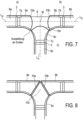
- FIG. 7 shows an application of the invention for a T-piece 6.
- This T-piece 6 has three pipe ends 7a, 7b and 7c, which are each connected to a coupling 3 with corresponding further pipe ends 8a, 8b and 8c arranged there, so that the couplings create a firm and tight connection of the respective pipe end pairs 7a/8a, 7b/8b and 7c/8c.
- the seals provided when connecting the pipe ends by means of the couplings are formed, but are not shown in the drawing.
- the hollow bodies 9a, 9b, 9c described in the present application are placed over the respective pipe end connections and the coupling and if these hollow bodies are designed as shrink tubing, a shrinking process can be used to produce a tight, conforming cover for the respective coupling and the other pipe sections assigned to them.
- the individual hollow bodies 9a, 9b and 9c are not cut off perpendicularly to their longitudinal axis La, Lb, Lc in their T-piece end, but have a round section 10a, 10b, 10c, which is also approximately partially circular (as in Figure 7 shown).
- the advantage of this round cut is that during the shrinking process this part of the hollow body extends as far as possible towards the center M of the T-piece, but the individual hollow body sections 9a, 9b, 9c can be pushed onto the T-piece separately from the respective ends a, b, c. Since the diameter of the T-piece increases towards the center, the shrinking process also means that the hollow bodies, i.e. the shrink tube, fit even more tightly there after the shrinking process than on the parts of the T-piece or the pipe ends 8a, 8b, 8c that have a smaller diameter.
- Figure 8 shows the presented variant of a T-piece with a hollow body, whereby the front ends 10a, 10b, 10c of the hollow body are cut in such a way that they either touch exactly in their front area, i.e. the area that comes into contact with the T-piece, or overlap slightly, e.g. by one or more cm.
- this then requires a special cut of the hollow body section 9c, while the hollow body sections 9a, 9b can have the same cut.
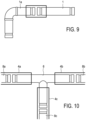
- Figure 9 shows the application of the invention on a straight pipe section 1, which is coupled with a pipe bend 19.
- the coupling itself is not shown, but the same applies to the overlying pipe ends as in the Figures 1 to 6 described.
- FIG 10 shows another variant of a T-piece 6, in which again three (uniform) hollow bodies 9a, 9b, 9c are located on the respective ends a, b, c and their coupling connection (not shown) as well as the adjacent pipe ends connected to the coupling.
- this type of T-piece all pipe connections and the hollow bodies are as shown in the Figures 1 to 6 described.
- Figure 11 shows the application of the invention on a pipe 1 with a sprinkler outlet 11.
- the sprinkler outlet 11 is usually screwed onto the pipe 1 or attached to it in some other way.
- the hollow body 4 and its casing of the sprinkler outlet and the coupling piece of the sprinkler ensure that this part of the sprinkler is sealed as well as possible.
- the hollow body material can be used, for example, in accordance with Figure 12 initially in the form of, for example, a rectangular sleeve 17, which is then placed or wrapped around the pipe connection or the pipe. So that the sleeve stays in place around the pipe ends or pipe connections or the pipe, the opposite ends 18a and 18b of the sleeve are placed around the pipe ends, pipe connections or pipes so that they overlap as often as possible, or multiple times, and the pipe ends are then fixed in place.
- Figure 13 shows the design of the pipe 1, which is enclosed by a hollow body 4, which initially has the shape of a sleeve 17.
- the ends 18a and 18b of the sleeve 17 overlap and if an adhesive is applied to at least the inside of the sleeve end 18a, this adheres to the outside of the cuff end 18b and thus fixes the cuff and allows the shrinking process without the cuff coming loose again.
- the entire inside of the cuff 17 is coated with an appropriate adhesive, so that when attaching the cuff to form the hollow body, it is not relevant which end is at the top and which is at the bottom.
- the adhesive ensures the best possible fixation of the surrounding sleeve on pipe 1.
- Figure 14 shows the variant for forming the hollow body around the pipe by means of a sleeve, in which the two sleeve ends 18a and 18b are (firmly) connected to one another with a closure rail 20.
- This closure rail can, but does not necessarily have to, be removed after the shrinking process.
- an adhesive on the inside of the hollow body of the sleeve is used in the present application, this should be an adhesive that is suitable for use with a shrink tube.
- An adhesive that is available under the name Hot melting Adhesive HS-TR-067 from Hongshang Heat Shrinkable Materials Co., Ltd., Shenzhen, China is suitable for this.
- the adhesive material does not have to cover the entire surface of the hollow body, but can also cover part of the surface. It should be remembered that the material contracts during the shrinking process and care must be taken to ensure that there is not too much adhesive material between the hollow body (shrink tube) and the pipe ends, coupling or pipe, so that no "adhesive bubbles" form on the inside of the hollow body.
- the "hot-melt adhesive” from Hongshang mentioned above is a suitable material, and many other adhesive materials can also be used and are equally suitable.
- the invention is particularly suitable for use where sprinkler systems and their pipes and pipe systems are installed, e.g. in buildings or operating facilities where cleaning must be carried out frequently with aggressive media and/or high-pressure cleaners.
- these can also be operating facilities for food production, e.g. cheese factories, sausage factories, slaughterhouses, milk processing plants, beverage manufacturers, slaughterhouses, meat cutting plants, etc. all production facilities where it is mandatory that the entire production facility is cleaned in recurring sections, e.g. once a day, once a week, etc. in accordance with strict hygiene regulations.
- the water-carrying (pipe arrangements, pipes, pipe ends, sprinklers and their outlets etc. of fire extinguishing systems are regularly installed both on the side walls and under the ceiling and cleaning the room within the facility regularly includes not only cleaning the machines and floors (e.g. tiles) in the facility, but also cleaning the entire room including all wall and ceiling areas.
- cleaning the pipe arrangements, pipes, pipe ends and thus coupling areas of the pipe ends as well as the sprinklers are cleaned repeatedly, e.g. with high-pressure cleaners, with a hard water jet from the high-pressure cleaner and the formation of the hollow body, e.g.
- a leakage monitor In order to monitor whether a chemical cleaner, or better still a high-pressure cleaner, gets into the area between the hollow body and the pipe or pipe connection from the outside during a cleaning process, it is also possible to provide a leakage monitor there, e.g. by arranging a moisture sensor 21 or the like. This moisture sensor is then connected wirelessly or by means of a line 22 to a control center in which the leakage monitoring signals are evaluated and in the event that there is a relevant amount of moisture between the hollow body and the pipe or pipe connection, this can be displayed in order to maintain the existing arrangement.
- the invention describes a pipe arrangement which consists of a pipe connection in which the part of the pipe arrangement which is encased and thus covered by the hollow body is protected as best as possible against environmental influences, as well as against the influences of cleaning materials and cleaning processes.
- the environmental influences are in particular the humidity, any aggressive materials and media contained in the air, also light, cleaning materials, chemicals, as well as any form of gas or water that acts on the pipe arrangement via a cleaning device, e.g. high-pressure cleaner.
Landscapes
- Engineering & Computer Science (AREA)
- General Engineering & Computer Science (AREA)
- Mechanical Engineering (AREA)
- Health & Medical Sciences (AREA)
- Public Health (AREA)
- Business, Economics & Management (AREA)
- Emergency Management (AREA)
- Pipe Accessories (AREA)
- Rigid Pipes And Flexible Pipes (AREA)
Claims (12)
- Ensemble de tuyaux pour une installation de lutte contre l'incendie, dans lequel l'installation de lutte contre l'incendie est réalisée par exemple en tant qu'installation de gicleurs, installation à eau de pulvérisation et/ou d'extinction, installation d'extinction à sec, installation d'extinction au gaz, installation à prise d'incendie ou similaire et est disposée de manière préférée dans une cantine, une cuisine, un hôpital, un atelier de production, en particulier dans un atelier de production de produits alimentaires, dans lequel l'ensemble de tuyaux est pourvu d'un dispositif de protection contre les influences extérieures, et l'ensemble de tuyaux est constituéd'un raccord de tuyau, qui présente deux extrémités de canalisation (1, 2), qui sont fixées l'une à l'autre au moyen d'un raccord mécanique (3) et pour laquelle les extrémités de canalisation (1, 2) tout comme le raccord mécanique (3) sont entourées d'un corps creux (4) déformable et le corps creux (4) repose étroitement contre les extrémités de canalisation (1, 2) et le raccord mécanique (3) après avoir adopté sa déformation finale et entoure ceux-ci par complémentarité de forme,et le corps creux (4) déformable peut être déformé par un traitement thermique ou peut être déformé par voie chimique et le corps creux (4) déformable est formé par un tuyau rétractable et/ou en posant un manchon en matériau de tuyau flexible rétractable autour du raccord de tuyau.
- Ensemble de tuyaux selon la revendication précédente, caractérisé en ce que le raccord mécanique (3) est formé à partir d'un couplage de tuyau constitué d'un ou de plusieurs segments ou d'un raccord à collerette constitué d'un unique ou de plusieurs segments pour le raccordement d'extrémités de canalisation à extrémité lisse ou pourvues de respectivement un filetage ou pourvues de respectivement au moins une rainure périphérique.
- Ensemble de tuyaux selon l'une quelconque des revendications précédentes, caractérisé en ce que l'ensemble de tuyaux présente une pièce en T, laquelle comprend trois extrémités de canalisation (a, b, c).
- Ensemble de tuyaux selon l'une quelconque des revendications précédentes, caractérisé en ce que le corps creux (4) présente une fonction d'étanchéité et contient par exemple une masse d'étanchéité ou un matériau.
- Ensemble de tuyaux selon l'une quelconque des revendications précédentes, caractérisé en ce que le corps creux (4) possède des propriétés ignifuges, par exemple est pourvu d'une protection pare-flamme.
- Ensemble de tuyaux selon l'une quelconque des revendications précédentes, caractérisé en ce que l'ensemble de tuyaux est équipé d'un moyen pour une surveillance de fuites, par exemple d'un capteur d'humidité (21) ou similaire.
- Ensemble de tuyaux selon l'une quelconque des revendications précédentes, caractérisé en ce que le raccord de tuyau est pourvu en supplément d'un enroulement, lequel présente au moins une ou plusieurs des propriétés suivantes :a) l'enroulement peut être déformé thermiquement ou peut être déformé par voie chimique et se rétracte lors de la déformation,b) l'enroulement présente des propriétés de soudage automatique ou de vulcanisation automatique,c) l'enroulement contient une masse d'étanchéité (5) supplémentaire,d) l'enroulement possède des propriétés ignifuges, est pourvu par exemple d'une protection pare-flamme,e) l'enroulement est pourvu d'une colle.
- Ensemble de tuyaux selon l'une quelconque des revendications précédentes, caractérisé en ce que le corps creux est pourvu au moins d'un côté d'une colle, laquelle est appliquée de préférence sur la totalité de la surface ou sur une surface partielle, par exemple en tant que film ou couche, avec une épaisseur prédéfinie.
- Installation de lutte contre l'incendie avec au moins un ensemble de tuyaux selon l'une quelconque des revendications précédentes, dans laquelle l'installation de lutte contre l'incendie est réalisée par exemple en tant qu'installation de gicleurs, installation à eau de pulvérisation ou d'extinction, installation d'extinction à sec, installation d'extinction au gaz ou installation de prise d'eau, de manière préférée pour une cantine, une cuisine, un hôpital ou un atelier de production, en particulier un atelier de production de produits alimentaires.
- Utilisation d'un ensemble de tuyaux selon l'une quelconque des revendications 1 à 8 dans un système de canalisations d'une installation de lutte contre l'incendie, par exemple d'une installation de gicleurs, d'une installation à eau de pulvérisation, d'une installation d'extinction, d'une installation de prise d'eau ou similaire, dans laquelle l'installation de lutte contre l'incendie est disposée dans une installation de production, par exemple un atelier de production de produits alimentaires, une cuisine, une cantine ou un hôpital et le système de canalisations est nettoyé depuis l'extérieur avec des nettoyants chimiques ou similaires récurrents, par exemple des nettoyeurs haute pression sur le site de montage du système de canalisations.
- Procédé de gainage d'un ensemble de tuyaux selon l'une quelconque des revendications 1 à 8, dans lequel la déformation du corps creux est effectuée par un traitement thermique et le traitement thermique est réalisé de telle manière qu'une quantité suffisante de chaleur agit sur le corps creux pour la déformation thermique du corps creux simultanément de différents endroits du corps creux, de préférence simultanément de la totalité de la périphérie pour ainsi obtenir un processus de rétractation dans la mesure du possible homogène.
- Ensemble de tuyaux selon l'une quelconque des revendications précédentes 1 à 8, caractérisé en ce que le corps creux (4) est formé en posant un manchon (17) autour du raccord de tuyau (1, 2, 3).
Applications Claiming Priority (2)
| Application Number | Priority Date | Filing Date | Title |
|---|---|---|---|
| DE102017116850.8A DE102017116850A1 (de) | 2017-07-25 | 2017-07-25 | Rohrverbindung |
| PCT/EP2018/070233 WO2019020719A1 (fr) | 2017-07-25 | 2018-07-25 | Agencement de tuyaux constitué d'un tuyau ou d'un raccord de tuyau |
Publications (2)
| Publication Number | Publication Date |
|---|---|
| EP3658813A1 EP3658813A1 (fr) | 2020-06-03 |
| EP3658813B1 true EP3658813B1 (fr) | 2025-01-08 |
Family
ID=63350495
Family Applications (1)
| Application Number | Title | Priority Date | Filing Date |
|---|---|---|---|
| EP18759034.4A Active EP3658813B1 (fr) | 2017-07-25 | 2018-07-25 | Agencement de tuyaux constitué d'un raccord de tuyau |
Country Status (5)
| Country | Link |
|---|---|
| US (2) | US12011627B2 (fr) |
| EP (1) | EP3658813B1 (fr) |
| CN (1) | CN110998164A (fr) |
| DE (1) | DE102017116850A1 (fr) |
| WO (1) | WO2019020719A1 (fr) |
Families Citing this family (3)
| Publication number | Priority date | Publication date | Assignee | Title |
|---|---|---|---|---|
| WO2021173868A1 (fr) * | 2020-02-25 | 2021-09-02 | Smart Pipe Company, Inc. | Procédé et appareil de dispositif de contrainte d'inspection en ligne permettant la réalisation d'inspections de joint en ligne |
| CN115111461B (zh) * | 2021-12-23 | 2024-01-30 | 重庆水务集团江津自来水有限公司 | 一种用于pe管道破裂的快速抢修方法 |
| CN120777478B (zh) * | 2025-09-10 | 2025-11-28 | 安徽省生宸源材料科技实业发展股份有限公司 | 一种具有监测与维护功能的管网及其连接方法 |
Citations (2)
| Publication number | Priority date | Publication date | Assignee | Title |
|---|---|---|---|---|
| US3565116A (en) * | 1968-09-12 | 1971-02-23 | White Motor Corp | Safety hose and fitting assembly |
| DE20116488U1 (de) * | 2001-10-09 | 2003-02-27 | Dannewitz GmbH & Co., 63571 Gelnhausen | Anordnung eines Klemmelements auf einem Rohrelement |
Family Cites Families (45)
| Publication number | Priority date | Publication date | Assignee | Title |
|---|---|---|---|---|
| US1165313A (en) * | 1914-12-22 | 1915-12-21 | Ralph F Bower | Fuse-nozzle. |
| US2027962A (en) * | 1933-03-03 | 1936-01-14 | Nat Carbon Co Inc | Production of articles from plastic compositions |
| GB433917A (en) * | 1934-12-12 | 1935-08-22 | Eustace Clark | Improvements in and connected with pipe joints |
| US3320355A (en) * | 1965-09-07 | 1967-05-16 | Aylwin R Booker | Heat shrinkable connector for electrical wire |
| DE1475860A1 (de) * | 1965-09-21 | 1969-03-27 | Stevens William Ernest | Rohrkupplung |
| GB1219768A (en) | 1967-04-26 | 1971-01-20 | Raychem Ltd | Covering means suitable for a pipe or shaft |
| US3438658A (en) * | 1967-08-08 | 1969-04-15 | William E Stevens | Pipe joint employing enlarged pipe ends |
| US3472538A (en) * | 1968-02-28 | 1969-10-14 | Pan American Petroleum Corp | Joint for coupling two tubular members together |
| GB1447048A (en) * | 1972-12-08 | 1976-08-25 | Raychem Corp | Heat-recoverable article |
| US4046406A (en) * | 1975-05-15 | 1977-09-06 | Resistoflex Corporation | Fire-safe jacket for fluid piping components |
| US4141576A (en) * | 1977-08-23 | 1979-02-27 | Lupke Manfred Arno Alfred | Heat shrinkable sleeve for coupling pipe sections |
| US4576403A (en) * | 1982-12-03 | 1986-03-18 | Jack Burkholder | Pressure fitting |
| DE8236832U1 (de) | 1982-12-30 | 1983-07-28 | Kabel- und Metallwerke Gutehoffnungshütte AG, 4500 Osnabrück | Rohrverbindung fuer eine warmwasser-fussbodenheizung |
| US4650228A (en) * | 1983-09-14 | 1987-03-17 | Raychem Corporation | Heat-recoverable coupling assembly |
| DE3814779C2 (de) * | 1988-04-21 | 1994-10-13 | Kabelmetal Electro Gmbh | Anordnung zum Umhüllen eines mit einem abzweigenden Teil versehenen Substrates |
| US5165735A (en) * | 1991-08-14 | 1992-11-24 | Berger Industries, Inc. | Electrical fitting for conduit connection |
| CN2221702Y (zh) * | 1995-05-11 | 1996-03-06 | 张学 | 卡扣式热收缩套 |
| GB9512285D0 (en) * | 1995-06-16 | 1995-08-16 | Rover Group | A pipe assembly |
| DE29818853U1 (de) | 1998-10-22 | 1999-01-07 | BRUGG Rohrsysteme GmbH, 31515 Wunstorf | Anschlußverbindung für ein Leitungsrohr für den Transport umweltgefährdender Medien |
| US6585054B1 (en) * | 1999-05-28 | 2003-07-01 | The Viking Corporation | Fast response sprinkler head and fire extinguishing system |
| DE10134512A1 (de) | 2001-07-16 | 2003-01-30 | Kebulin Ges Kettler & Co Kg | Korrosionsschutz-System für insbesondere erdverlegte Rohrleitungen, Rohrformstücke, Behälter und dgl. |
| DE10144277C1 (de) | 2001-09-08 | 2003-03-06 | Airbus Gmbh | Rohrleitungsverbindung |
| CN200972037Y (zh) * | 2006-11-27 | 2007-11-07 | 周伟 | 地下燃气管道钢塑转换接头 |
| KR20090108629A (ko) * | 2007-01-10 | 2009-10-15 | 타이코 파이어 프로덕츠 엘피 | 배관 어셈블리의 건식 끼워맞춤 연결부들을 검사 및 밀봉하기 위한 방법들 및 시스템들 |
| DE102008025085A1 (de) | 2008-05-26 | 2009-12-03 | Pirtek (Deutschland) Gmbh | Fluidschlauch mit Kennzeichnung |
| CN201412612Y (zh) * | 2009-06-10 | 2010-02-24 | 成都长江热缩材料有限公司 | 圆管式热缩套管 |
| WO2012009742A1 (fr) * | 2010-07-22 | 2012-01-26 | Promat Australia Pty Ltd. | Couverture s'opposant à la fumée, au son et à l'incendie |
| EP2481966A1 (fr) * | 2011-02-01 | 2012-08-01 | Uponor Innovation AB | Bague de serrage |
| CN202040471U (zh) * | 2011-04-17 | 2011-11-16 | 李志雄 | 一种高频感应加热连接管件 |
| CN202381914U (zh) * | 2011-11-18 | 2012-08-15 | 余张法 | 不锈钢卡压式管道连接件防护装置 |
| US9046200B2 (en) * | 2012-01-03 | 2015-06-02 | Berry Plastics Corporation | Heat-shrinkable tube covering |
| US20130206927A1 (en) * | 2012-02-14 | 2013-08-15 | Greenfield Mfg Co Inc | Threaded flange plate for hanger rod |
| US20130233435A1 (en) * | 2012-03-10 | 2013-09-12 | Atkore International, Inc. | Integral coupling for joining conduit sections |
| US20140231103A1 (en) * | 2013-02-15 | 2014-08-21 | Victaulic Company | Identification Sleeve for Flexible Conduit |
| GB2509834B (en) * | 2013-12-20 | 2014-12-03 | Thermaflue Systems Ltd | Safety shield for a pipe joint |
| DE102014100155A1 (de) * | 2014-01-08 | 2015-07-09 | Christian Jedrosek | Verfahren zur Kontrolle und/oder Reparatur von Flanschverbindungen und zugehörige Flanschverbindung |
| CN204254157U (zh) * | 2014-10-20 | 2015-04-08 | 青岛泰能科技实业发展有限公司 | 三通外护补口结构 |
| FR3028915B1 (fr) * | 2014-11-21 | 2017-04-21 | Sartorius Stedim Fmt Sas | Systeme de connexion fluidique et procede de fabrication |
| CN205101781U (zh) * | 2015-10-30 | 2016-03-23 | 成都长江热缩材料有限公司 | 利于防管道腐蚀的热缩套管 |
| CN205118569U (zh) * | 2015-11-03 | 2016-03-30 | 深圳华瀚管廊物业服务有限公司 | 一种耐热pe管道 |
| CN205909882U (zh) * | 2015-12-03 | 2017-01-25 | 西南石油大学 | 一种便用式皂膜流量计 |
| CN205261019U (zh) * | 2015-12-21 | 2016-05-25 | 广州机施建设集团有限公司 | 燃气管道悬吊保护结构 |
| CN105423041A (zh) * | 2015-12-25 | 2016-03-23 | 河南中久安科技有限公司 | 一种弯钢塑转换管件及其防腐生产工艺 |
| EP3463792A4 (fr) * | 2016-05-31 | 2020-01-08 | Berry Plastics Corporation | Patch de fermeture |
| CN106583954A (zh) * | 2016-11-28 | 2017-04-26 | 王有洪 | 一种采用焊接连接的衬塑钢管的制备方法 |
-
2017
- 2017-07-25 DE DE102017116850.8A patent/DE102017116850A1/de not_active Withdrawn
-
2018
- 2018-07-25 EP EP18759034.4A patent/EP3658813B1/fr active Active
- 2018-07-25 WO PCT/EP2018/070233 patent/WO2019020719A1/fr not_active Ceased
- 2018-07-25 US US16/632,300 patent/US12011627B2/en active Active
- 2018-07-25 CN CN201880049923.2A patent/CN110998164A/zh active Pending
-
2024
- 2024-04-10 US US18/631,702 patent/US20240325806A1/en active Pending
Patent Citations (2)
| Publication number | Priority date | Publication date | Assignee | Title |
|---|---|---|---|---|
| US3565116A (en) * | 1968-09-12 | 1971-02-23 | White Motor Corp | Safety hose and fitting assembly |
| DE20116488U1 (de) * | 2001-10-09 | 2003-02-27 | Dannewitz GmbH & Co., 63571 Gelnhausen | Anordnung eines Klemmelements auf einem Rohrelement |
Also Published As
| Publication number | Publication date |
|---|---|
| EP3658813A1 (fr) | 2020-06-03 |
| WO2019020719A1 (fr) | 2019-01-31 |
| CN110998164A (zh) | 2020-04-10 |
| US20200360749A1 (en) | 2020-11-19 |
| DE102017116850A1 (de) | 2019-01-31 |
| US12011627B2 (en) | 2024-06-18 |
| US20240325806A1 (en) | 2024-10-03 |
Similar Documents
| Publication | Publication Date | Title |
|---|---|---|
| EP3658813B1 (fr) | Agencement de tuyaux constitué d'un raccord de tuyau | |
| DE4122665A1 (de) | Sprinkler fuer selbsttaetige feuerloeschanlagen | |
| DE2358325A1 (de) | Vorrichtung fuer rohrverbindungen | |
| DE3803410A1 (de) | Verfahren zur reinigung und beschichtung von zur wasserfuehrung bestimmten rohrleitungen | |
| AT391931B (de) | Brandabschlussmanschette | |
| EP0044468B1 (fr) | Elément de tuyauterie à isolation thermique et système de tuyauterie comportant un tel élément et procédés de fabrication dudit élément et dudit système de tuyauterie | |
| WO2013110204A1 (fr) | Procédé pour relier une pièce de raccordement à un conduit thermo-isolé | |
| DE69927806T2 (de) | Isolationsmodule, System und Verfahren zu seiner Installation und Herstellung | |
| CH678221A5 (fr) | ||
| EP3282164B1 (fr) | Système de conduit | |
| DE2056860B2 (de) | Verfahren zum Herstellen eines Schutzuberzuges an Absperrarmaturen | |
| DE4446001C2 (de) | Flexible Gasleitung | |
| EP2163298A2 (fr) | Agencement de fenêtre sur un tube de pression | |
| DE10002974B4 (de) | Rohrkupplung mit Toleranzausgleich | |
| DE202013101069U1 (de) | Verbindungsmuffe | |
| DE69110876T2 (de) | Gerät zur verhinderung von wasserschäden aufgrund undichter stellen in wasserleitungen in gebäuden. | |
| DE3509391C2 (fr) | ||
| EP0017846B1 (fr) | Enveloppe pour conduits ou tuyaux couverts ou noyés servant comme échangeurs de chaleur | |
| DE19634305A1 (de) | Wartungsfreie Vorrichtung zur rauch- und brandsicheren Abschottung einer Lüftungsrohrleitung | |
| DE202008010465U1 (de) | Vorrichtung zur Isolierung eines Rohrleitungssystems | |
| DE19919756A1 (de) | Doppelwandrohre, -platten oder -behälter mit Leckageüberwachungseinrichtung und Verfahren zur Herstellung derartiger doppelwandiger Rohre, Platten oder Behälter | |
| DE29505091U1 (de) | Armaturenanschluß | |
| AT393011B (de) | Leitungselement | |
| DE20321169U1 (de) | Rohrschalldämpfer aus Kunststoff für Lüftungsanlagen | |
| DE4223711A1 (de) | Online-Verfahren zum Sanieren von Rohrleitungsisolierungen |
Legal Events
| Date | Code | Title | Description |
|---|---|---|---|
| STAA | Information on the status of an ep patent application or granted ep patent |
Free format text: STATUS: UNKNOWN |
|
| STAA | Information on the status of an ep patent application or granted ep patent |
Free format text: STATUS: THE INTERNATIONAL PUBLICATION HAS BEEN MADE |
|
| PUAI | Public reference made under article 153(3) epc to a published international application that has entered the european phase |
Free format text: ORIGINAL CODE: 0009012 |
|
| STAA | Information on the status of an ep patent application or granted ep patent |
Free format text: STATUS: REQUEST FOR EXAMINATION WAS MADE |
|
| 17P | Request for examination filed |
Effective date: 20200225 |
|
| AK | Designated contracting states |
Kind code of ref document: A1 Designated state(s): AL AT BE BG CH CY CZ DE DK EE ES FI FR GB GR HR HU IE IS IT LI LT LU LV MC MK MT NL NO PL PT RO RS SE SI SK SM TR |
|
| AX | Request for extension of the european patent |
Extension state: BA ME |
|
| DAV | Request for validation of the european patent (deleted) | ||
| DAX | Request for extension of the european patent (deleted) | ||
| STAA | Information on the status of an ep patent application or granted ep patent |
Free format text: STATUS: EXAMINATION IS IN PROGRESS |
|
| 17Q | First examination report despatched |
Effective date: 20220310 |
|
| P01 | Opt-out of the competence of the unified patent court (upc) registered |
Effective date: 20230602 |
|
| GRAP | Despatch of communication of intention to grant a patent |
Free format text: ORIGINAL CODE: EPIDOSNIGR1 |
|
| STAA | Information on the status of an ep patent application or granted ep patent |
Free format text: STATUS: GRANT OF PATENT IS INTENDED |
|
| INTG | Intention to grant announced |
Effective date: 20240404 |
|
| GRAJ | Information related to disapproval of communication of intention to grant by the applicant or resumption of examination proceedings by the epo deleted |
Free format text: ORIGINAL CODE: EPIDOSDIGR1 |
|
| STAA | Information on the status of an ep patent application or granted ep patent |
Free format text: STATUS: EXAMINATION IS IN PROGRESS |
|
| INTC | Intention to grant announced (deleted) | ||
| GRAP | Despatch of communication of intention to grant a patent |
Free format text: ORIGINAL CODE: EPIDOSNIGR1 |
|
| STAA | Information on the status of an ep patent application or granted ep patent |
Free format text: STATUS: GRANT OF PATENT IS INTENDED |
|
| INTG | Intention to grant announced |
Effective date: 20240822 |
|
| RAP1 | Party data changed (applicant data changed or rights of an application transferred) |
Owner name: MINIMAX VIKING PATENT MANAGEMENT GMBH |
|
| GRAS | Grant fee paid |
Free format text: ORIGINAL CODE: EPIDOSNIGR3 |
|
| GRAA | (expected) grant |
Free format text: ORIGINAL CODE: 0009210 |
|
| STAA | Information on the status of an ep patent application or granted ep patent |
Free format text: STATUS: THE PATENT HAS BEEN GRANTED |
|
| AK | Designated contracting states |
Kind code of ref document: B1 Designated state(s): AL AT BE BG CH CY CZ DE DK EE ES FI FR GB GR HR HU IE IS IT LI LT LU LV MC MK MT NL NO PL PT RO RS SE SI SK SM TR |
|
| REG | Reference to a national code |
Ref country code: GB Ref legal event code: FG4D Free format text: NOT ENGLISH |
|
| REG | Reference to a national code |
Ref country code: CH Ref legal event code: EP |
|
| REG | Reference to a national code |
Ref country code: DE Ref legal event code: R096 Ref document number: 502018015489 Country of ref document: DE |
|
| REG | Reference to a national code |
Ref country code: IE Ref legal event code: FG4D Free format text: LANGUAGE OF EP DOCUMENT: GERMAN |
|
| REG | Reference to a national code |
Ref country code: LT Ref legal event code: MG9D |
|
| REG | Reference to a national code |
Ref country code: NL Ref legal event code: MP Effective date: 20250108 |
|
| PG25 | Lapsed in a contracting state [announced via postgrant information from national office to epo] |
Ref country code: NL Free format text: LAPSE BECAUSE OF FAILURE TO SUBMIT A TRANSLATION OF THE DESCRIPTION OR TO PAY THE FEE WITHIN THE PRESCRIBED TIME-LIMIT Effective date: 20250108 |
|
| PG25 | Lapsed in a contracting state [announced via postgrant information from national office to epo] |
Ref country code: RS Free format text: LAPSE BECAUSE OF FAILURE TO SUBMIT A TRANSLATION OF THE DESCRIPTION OR TO PAY THE FEE WITHIN THE PRESCRIBED TIME-LIMIT Effective date: 20250408 |
|
| PG25 | Lapsed in a contracting state [announced via postgrant information from national office to epo] |
Ref country code: FI Free format text: LAPSE BECAUSE OF FAILURE TO SUBMIT A TRANSLATION OF THE DESCRIPTION OR TO PAY THE FEE WITHIN THE PRESCRIBED TIME-LIMIT Effective date: 20250108 |
|
| PG25 | Lapsed in a contracting state [announced via postgrant information from national office to epo] |
Ref country code: PL Free format text: LAPSE BECAUSE OF FAILURE TO SUBMIT A TRANSLATION OF THE DESCRIPTION OR TO PAY THE FEE WITHIN THE PRESCRIBED TIME-LIMIT Effective date: 20250108 |
|
| PG25 | Lapsed in a contracting state [announced via postgrant information from national office to epo] |
Ref country code: ES Free format text: LAPSE BECAUSE OF FAILURE TO SUBMIT A TRANSLATION OF THE DESCRIPTION OR TO PAY THE FEE WITHIN THE PRESCRIBED TIME-LIMIT Effective date: 20250108 |
|
| PG25 | Lapsed in a contracting state [announced via postgrant information from national office to epo] |
Ref country code: NO Free format text: LAPSE BECAUSE OF FAILURE TO SUBMIT A TRANSLATION OF THE DESCRIPTION OR TO PAY THE FEE WITHIN THE PRESCRIBED TIME-LIMIT Effective date: 20250408 Ref country code: IS Free format text: LAPSE BECAUSE OF FAILURE TO SUBMIT A TRANSLATION OF THE DESCRIPTION OR TO PAY THE FEE WITHIN THE PRESCRIBED TIME-LIMIT Effective date: 20250508 |
|
| PG25 | Lapsed in a contracting state [announced via postgrant information from national office to epo] |
Ref country code: HR Free format text: LAPSE BECAUSE OF FAILURE TO SUBMIT A TRANSLATION OF THE DESCRIPTION OR TO PAY THE FEE WITHIN THE PRESCRIBED TIME-LIMIT Effective date: 20250108 |
|
| PG25 | Lapsed in a contracting state [announced via postgrant information from national office to epo] |
Ref country code: LV Free format text: LAPSE BECAUSE OF FAILURE TO SUBMIT A TRANSLATION OF THE DESCRIPTION OR TO PAY THE FEE WITHIN THE PRESCRIBED TIME-LIMIT Effective date: 20250108 Ref country code: PT Free format text: LAPSE BECAUSE OF FAILURE TO SUBMIT A TRANSLATION OF THE DESCRIPTION OR TO PAY THE FEE WITHIN THE PRESCRIBED TIME-LIMIT Effective date: 20250508 |
|
| PG25 | Lapsed in a contracting state [announced via postgrant information from national office to epo] |
Ref country code: BG Free format text: LAPSE BECAUSE OF FAILURE TO SUBMIT A TRANSLATION OF THE DESCRIPTION OR TO PAY THE FEE WITHIN THE PRESCRIBED TIME-LIMIT Effective date: 20250108 Ref country code: GR Free format text: LAPSE BECAUSE OF FAILURE TO SUBMIT A TRANSLATION OF THE DESCRIPTION OR TO PAY THE FEE WITHIN THE PRESCRIBED TIME-LIMIT Effective date: 20250409 |
|
| PG25 | Lapsed in a contracting state [announced via postgrant information from national office to epo] |
Ref country code: SE Free format text: LAPSE BECAUSE OF FAILURE TO SUBMIT A TRANSLATION OF THE DESCRIPTION OR TO PAY THE FEE WITHIN THE PRESCRIBED TIME-LIMIT Effective date: 20250108 |
|
| PG25 | Lapsed in a contracting state [announced via postgrant information from national office to epo] |
Ref country code: SM Free format text: LAPSE BECAUSE OF FAILURE TO SUBMIT A TRANSLATION OF THE DESCRIPTION OR TO PAY THE FEE WITHIN THE PRESCRIBED TIME-LIMIT Effective date: 20250108 |
|
| REG | Reference to a national code |
Ref country code: DE Ref legal event code: R097 Ref document number: 502018015489 Country of ref document: DE |
|
| PG25 | Lapsed in a contracting state [announced via postgrant information from national office to epo] |
Ref country code: DK Free format text: LAPSE BECAUSE OF FAILURE TO SUBMIT A TRANSLATION OF THE DESCRIPTION OR TO PAY THE FEE WITHIN THE PRESCRIBED TIME-LIMIT Effective date: 20250108 |
|
| PGFP | Annual fee paid to national office [announced via postgrant information from national office to epo] |
Ref country code: DE Payment date: 20250811 Year of fee payment: 8 |
|
| PGFP | Annual fee paid to national office [announced via postgrant information from national office to epo] |
Ref country code: GB Payment date: 20250724 Year of fee payment: 8 |
|
| PGFP | Annual fee paid to national office [announced via postgrant information from national office to epo] |
Ref country code: FR Payment date: 20250723 Year of fee payment: 8 |
|
| PG25 | Lapsed in a contracting state [announced via postgrant information from national office to epo] |
Ref country code: EE Free format text: LAPSE BECAUSE OF FAILURE TO SUBMIT A TRANSLATION OF THE DESCRIPTION OR TO PAY THE FEE WITHIN THE PRESCRIBED TIME-LIMIT Effective date: 20250108 Ref country code: CZ Free format text: LAPSE BECAUSE OF FAILURE TO SUBMIT A TRANSLATION OF THE DESCRIPTION OR TO PAY THE FEE WITHIN THE PRESCRIBED TIME-LIMIT Effective date: 20250108 |
|
| PG25 | Lapsed in a contracting state [announced via postgrant information from national office to epo] |
Ref country code: RO Free format text: LAPSE BECAUSE OF FAILURE TO SUBMIT A TRANSLATION OF THE DESCRIPTION OR TO PAY THE FEE WITHIN THE PRESCRIBED TIME-LIMIT Effective date: 20250108 |
|
| PG25 | Lapsed in a contracting state [announced via postgrant information from national office to epo] |
Ref country code: SK Free format text: LAPSE BECAUSE OF FAILURE TO SUBMIT A TRANSLATION OF THE DESCRIPTION OR TO PAY THE FEE WITHIN THE PRESCRIBED TIME-LIMIT Effective date: 20250108 |
|
| PLBE | No opposition filed within time limit |
Free format text: ORIGINAL CODE: 0009261 |
|
| STAA | Information on the status of an ep patent application or granted ep patent |
Free format text: STATUS: NO OPPOSITION FILED WITHIN TIME LIMIT |
|
| REG | Reference to a national code |
Ref country code: CH Ref legal event code: L10 Free format text: ST27 STATUS EVENT CODE: U-0-0-L10-L00 (AS PROVIDED BY THE NATIONAL OFFICE) Effective date: 20251119 |
|
| 26N | No opposition filed |
Effective date: 20251009 |
|
| PG25 | Lapsed in a contracting state [announced via postgrant information from national office to epo] |
Ref country code: IT Free format text: LAPSE BECAUSE OF FAILURE TO SUBMIT A TRANSLATION OF THE DESCRIPTION OR TO PAY THE FEE WITHIN THE PRESCRIBED TIME-LIMIT Effective date: 20250108 |
|
| REG | Reference to a national code |
Ref country code: CH Ref legal event code: H13 Free format text: ST27 STATUS EVENT CODE: U-0-0-H10-H13 (AS PROVIDED BY THE NATIONAL OFFICE) Effective date: 20260224 |
|
| PG25 | Lapsed in a contracting state [announced via postgrant information from national office to epo] |
Ref country code: LU Free format text: LAPSE BECAUSE OF NON-PAYMENT OF DUE FEES Effective date: 20250725 |
|
| REG | Reference to a national code |
Ref country code: BE Ref legal event code: MM Effective date: 20250731 |
|
| PG25 | Lapsed in a contracting state [announced via postgrant information from national office to epo] |
Ref country code: BE Free format text: LAPSE BECAUSE OF NON-PAYMENT OF DUE FEES Effective date: 20250731 |
|
| PG25 | Lapsed in a contracting state [announced via postgrant information from national office to epo] |
Ref country code: CH Free format text: LAPSE BECAUSE OF NON-PAYMENT OF DUE FEES Effective date: 20250731 |